


Manual
Expert Net Control 2111
Expert Net Control 2191
© 2021 GUDE Systems GmbH
Manual Ver. 1.3.0
from Firmware Ver. 1.3

2
Expert Net Control 2111/2191 © 2021 GUDE Systems GmbH

Table of contents
1. Device Description 6
1.1 Security Advice ....................................................................................................... 7
1.2 Content of Delivery ................................................................................................. 7
1.3 Description ............................................................................................................. 7
1.4 Installation ............................................................................................................. 9
1.4.1 Terminal Assignment ............................................................................................. 10
1.5 Redundant Voltage Supply .................................................................................... 11
1.6 Technical Specifications ........................................................................................ 11
1.7 Sensor .................................................................................................................. 12
2. Operating 15
2.1 Operating the device directly ................................................................................ 16
2.2 Control Panel ........................................................................................................ 17
2.3 Maintenance ........................................................................................................ 19
2.3.1 Maintenance Page ................................................................................................. 21
2.3.2 Configuration Management .................................................................................. 22
2.3.3 Bootloader Activation ............................................................................................ 24
2.4 GSM ..................................................................................................................... 25
2.4.1 SMS ........................................................................................................................ 27
2.4.1.1
2.4.1.1.1 Port: Query Port State ................................................................................. 27
2.4.1.1.2 Port: Simple Switching ................................................................................ 27
2.4.1.1.3 Port: Advanced Switching (Batchmode) ..................................................... 28
2.4.1.1.4 Port: Advanced Switching (coldstart) ......................................................... 28
2.4.1.1.5 Configuration: Read .................................................................................... 29
2.4.1.1.6 Configuration: Write ................................................................................... 29
2.4.1.1.7 Configuration: All Parameter ...................................................................... 30
2.4.1.1.8 Sensors: Query State ................................................................................... 30
2.4.1.1.9 Query Device State ...................................................................................... 31
2.4.1.2
2.4.1.2.1 SMS command replies ................................................................................. 31
2.4.1.2.2 Status Change Report SMS ......................................................................... 32
2.4.2 Voice Call ................................................................................................................ 32
2.4.2.1
2.4.2.1.1 Port Menu ................................................................................................... 33
2.4.2.1.2 Status Menu ................................................................................................ 34
2.4.2.1.3 Parameter Description ................................................................................ 34
2.4.3 Port Commands ..................................................................................................... 34
2.4.4 Security .................................................................................................................. 36
SMS Commands ............................................................................................... 27
SMS replies ...................................................................................................... 31
Menu ................................................................................................................ 32
3. Configuration 38
3.1 Output Ports ......................................................................................................... 39
3
Expert Net Control 2111/2191 © 2021 GUDE Systems GmbH

Table of contents
3.1.1 Watchdog ............................................................................................................... 40
3.2 Input Ports ............................................................................................................ 42
3.3 Ethernet ............................................................................................................... 43
3.3.1 IP Address ............................................................................................................... 43
3.3.2 IP ACL ..................................................................................................................... 44
3.3.3 HTTP ....................................................................................................................... 45
3.4 Protocols .............................................................................................................. 46
3.4.1 Console ................................................................................................................... 47
3.4.2 Syslog ..................................................................................................................... 49
3.4.3 SNMP ...................................................................................................................... 49
3.4.4 Radius ..................................................................................................................... 50
3.4.5 Modbus TCP ........................................................................................................... 52
3.5 Clock ..................................................................................................................... 52
3.5.1 NTP ......................................................................................................................... 53
3.5.2 Timer ...................................................................................................................... 54
3.5.3 Timer Configuration ............................................................................................... 54
3.6 Sensors ................................................................................................................. 61
3.6.1 Port Switching ........................................................................................................ 62
3.7 E-Mail ................................................................................................................... 63
3.8 Front Panel ........................................................................................................... 65
3.9 GSM ..................................................................................................................... 65
3.9.1 GSM General .......................................................................................................... 65
3.9.2 GSM Misc ............................................................................................................... 66
3.9.3 GSM Phonebook .................................................................................................... 67
3.9.4 GSM SIM Card ........................................................................................................ 67
3.9.5 GSM Provider ......................................................................................................... 68
4. Specifications 69
4.1 IP ACL ................................................................................................................... 70
4.2 IPv6 ...................................................................................................................... 70
4.3 Radius ................................................................................................................... 71
4.4 Automated Access ................................................................................................ 71
4.5 SNMP ................................................................................................................... 72
4.5.1 Device MIB 2111 .................................................................................................... 74
4.5.2 Device MIB 2191 .................................................................................................... 76
4.6 SSL ........................................................................................................................ 77
4.7 Console ................................................................................................................. 78
4.7.1 SSH ......................................................................................................................... 82
4.7.2 Push Messages ....................................................................................................... 83
4.7.3 Console Cmd 2111 ................................................................................................. 83
4.7.4 Console Cmd 2191 ................................................................................................. 90
4.8 Modbus TCP ......................................................................................................... 98
4
Expert Net Control 2111/2191 © 2021 GUDE Systems GmbH

Table of contents
4.9 Messages ............................................................................................................ 103
5. Support 104
5.1 Data Security ...................................................................................................... 105
5.2 Contact ............................................................................................................... 105
5.3 Declaration of Conformity ................................................................................... 106
5.4 FAQ .................................................................................................................... 106
Index
108
5
Expert Net Control 2111/2191 © 2021 GUDE Systems GmbH

Device Description

Device Description
1 Device Description
1.1 Security Advice
· The device must be installed only by qualified personnel according to the following
installation and operating instructions.
· The manufacturer does not accept responsibility in case of improper use of the
device and particularly any use of equipment that may cause personal injury or material damage.
· The device contains no user-maintainable parts. All maintenance has to be performed by factory trained service personnel.
· The device may only be connected via a low voltage power supply to 230V AC (50
Hz or 60 Hz) power supply sockets.
· The device is intended for indoor use only. Do NOT install them in an area where excessive moisture or heat is present.
· Because of safety and approval issues it is not allowed to modify the device without
our permission.
· The device is NOT a toy. It has to be used or stored out of range of children.
· Care about packaging material. Plastics has to be stored out of range of children.
Please recycle the packaging materials.
· In case of further questions, about installation, operation or usage of the device,
which are not clear after reading the manual, please do not hesitate to ask our support team.
1.2 Content of Delivery
The package includes:
· Expert Net Control 2111 / 2191
· Power Supply Unit 7903 (12V DC, 1 A) (only ENC 2111-1 / 2191-1)
· GSM Antenna (only ENC 2191)
· Quick Start Guide
1.3 Description
The Expert Net Control 2111 / 2191 can switch 4 different relay outputs and monitor
12 passive signal inputs. The device has the following features:
· 4 switchable, potential-free relay outputs with change-over connectors (NO and NC),
high switching voltage 36 V, 3 A
· Relays dispose of high contact reliability also at very small loads
· 12 passive inputs for monitoring NO and NC devices, e.g. door contacts, smoke de-
tectors, leakage sensors etc.
· Each signal input includes a 12 V connector for supply of NO/NC devices
· A clearly visible LED display on the device reveals total current, IP address, sensor
data and error reports
· LED display for status of power supply, inputs/outputs and GSM (2191)
· 2 inputs for redundant power supply (12 V DC) via 2 external power supply units
(one included in delivery)
7
Expert Net Control 2111/2191 © 2021 GUDE Systems GmbH

Device Description
· For 2111-2 / 2191-2 additional power supply by Power-over-Ethernet (PoE) possible
· 4 interfaces for optional sensors for environmental monitoring (temperature, humidity
and air pressure)
· Console commands via SSH, Telnet and serial interface
· SSH support with public key and passwords
· Individually parameterisable switch-on delay of all outputs
· Programmable timetables and turn-on/turn-off sequences
· Individually adjustable watchdog for each output, which switches depending on ac-
cessibility (network ping)
· Dual TCP/IP stack with IPv4 and IPv6 support (IPv6-ready)
· Control and monitoring of the device via Ethernet with an integrated web server with
SSL encryption (TLS 1.1, 1.2, 1.3)
· Control and configuration with CGI parameters and JSON messages via HTTP
(REST API)
· SNMP (v1, v2c and v3, traps)
· Modbus TCP support
· Radius support
· Generation of messages (e-mail, syslog and SNMP traps) and switching of relays
depending on sensor measurement limits
· Firmware update during operation via Ethernet possible
· Encrypted e-mails (SSL, STARTTLS)
· Access protection through IP access control
· Low own consumption
· Developed and produced in Germany
Only Expert Net Control 2191:
· 4 relay ports individually switchable via voicecall and SMS
· GSM admin and user access for all Power Ports definable
· For pre-paid and post-paid SIM cards (SIM card not included)
· Triband network
· FreeCall: Predefined action upon toll-free incoming call from a specific number
8
Expert Net Control 2111/2191 © 2021 GUDE Systems GmbH
Device Description
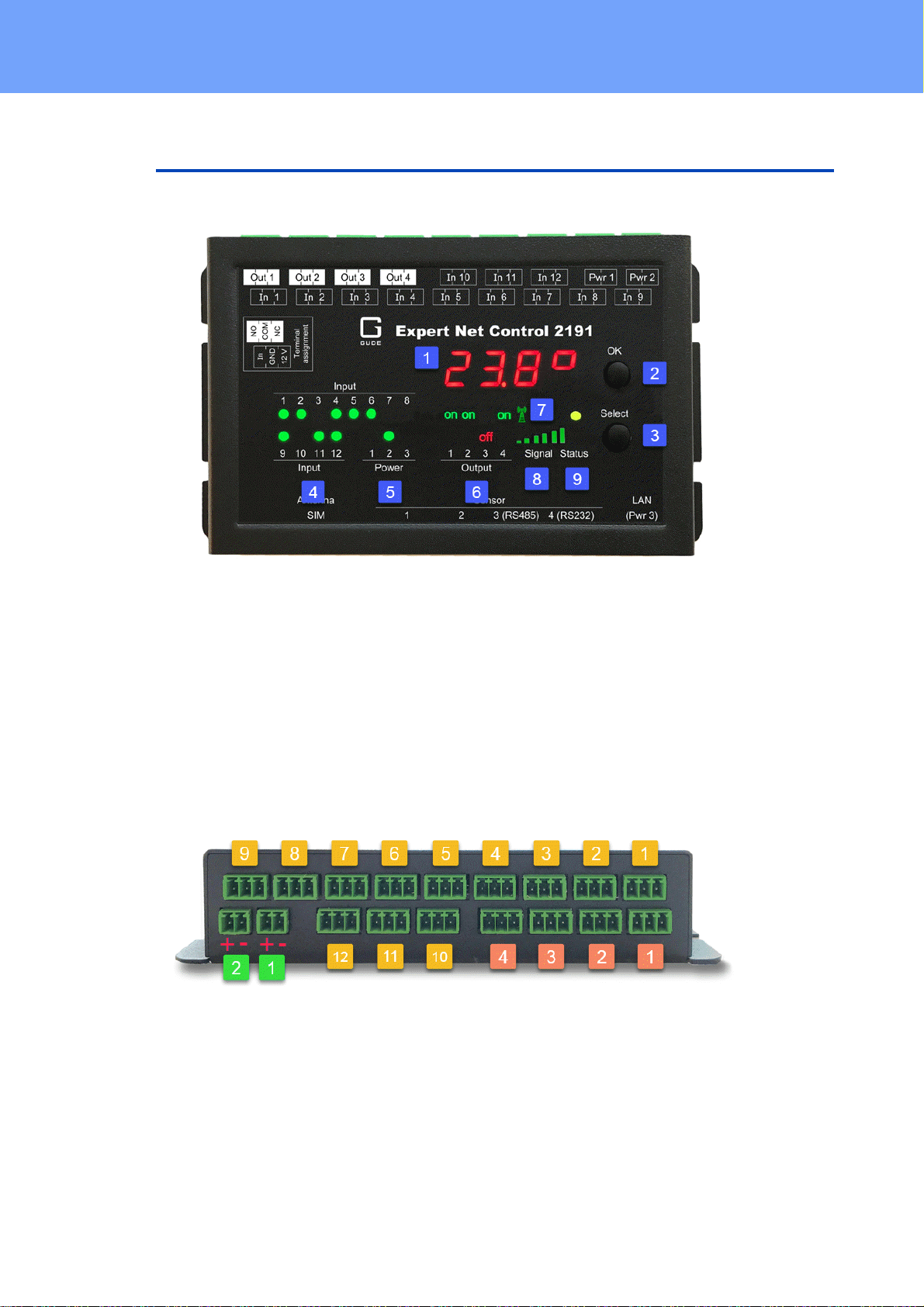
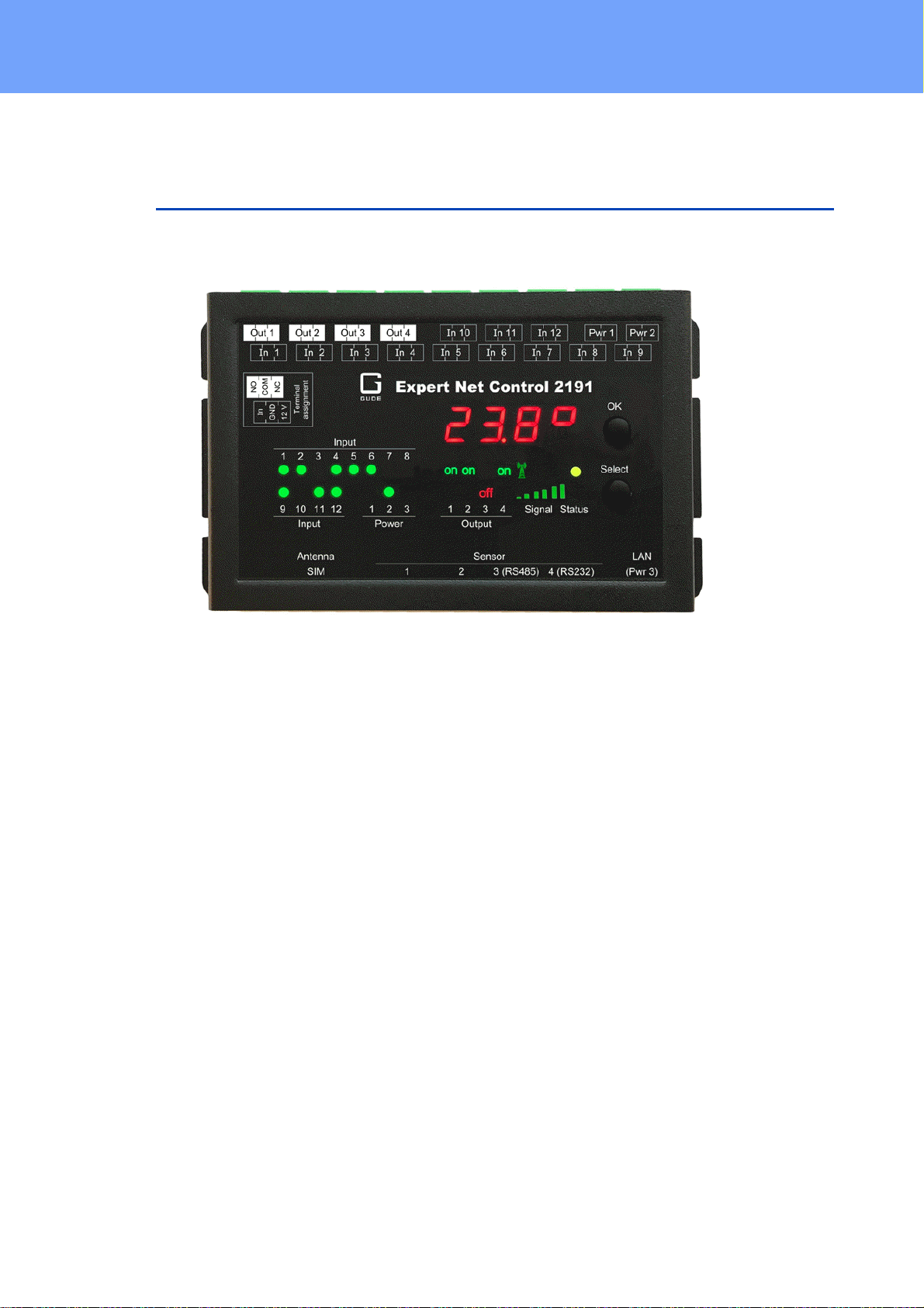
1.4 Installation
1. Sensor Information (7-segment display)
2. OK Button
3. Select Button
4. 12 LED's signaling the state of the Inputs
5. LED display for power supply (1 = Pwr1, 2 = Pwr2, 3 = Pwr3 (POE) )
6. 4 plain text displays (on/off) for the state of the Output Ports
7. Signal Tower indicator LED for GSM Connection (only ENC 2191)
8. GSM signal strength (only ENC 2191)
9. Status LED
12 passive inputs (yellow)
4 potential-free relay outputs (red)
2 Connectors (Pwr1 + Pwr2) for power supply 12 V DC, 1 A (green)
9
Expert Net Control 2111/2191 © 2021 GUDE Systems GmbH
Device Description
This means that there is only a connection between the center pin (COM) and the NC-pin (Normally Closed) for the output ports in the "Off" state. If the relay is in the "On" state,
then there is only contact from the center pin (COM) to the
NO-pin (Normally Open).
The digital signal inputs (input ports) go to the logic state
"LOW" when the pin "In" and the center pin "GND" are
bridged, otherwise the state is "HI". The text outputs associated with the "LOW" and "HI" states can be defined in the Input Ports configuration . In the default configuration, the
logic states are inverted so that the state "HI" is assumed for
a bridged contact. In addition, a 12 V power supply can be
activated in the Sensor configuration on the 12V-pin. The
power of the 12 V supply (high = 600 mA, low = 400 mA) is
adjustable.
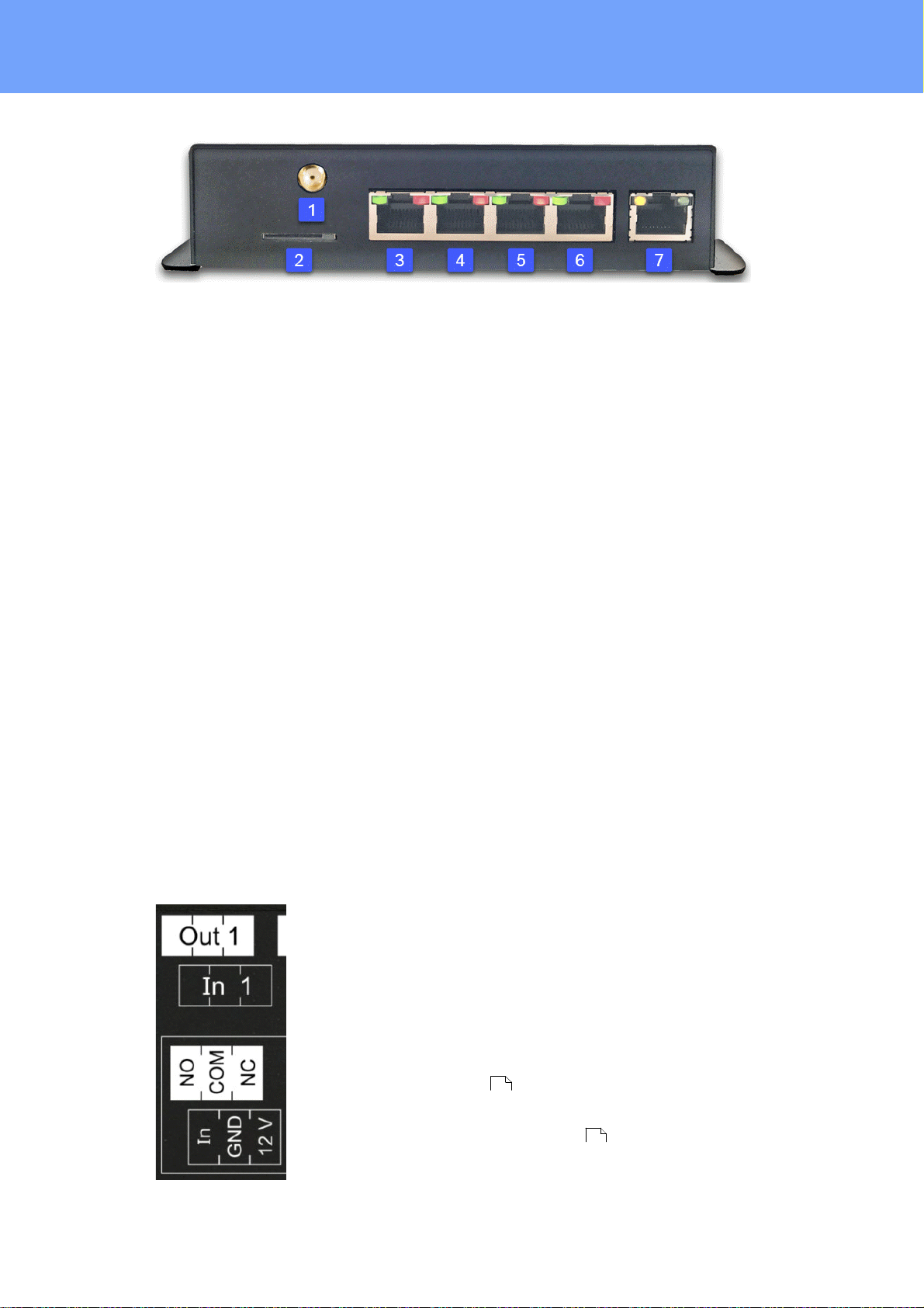
1. GSM antenna connector (only ENC 2191)
2. SIM card slot (only ENC 2191)
3. Connector Sensor Port 1
4. Connector Sensor Port 2
5. Connector Sensor Port 3 (RS485)
6. Connector Sensor Port 4 (RS232)
7. Ethernet connector (RJ45) (with Pwr3 = POE only ENC 2111-2 / 2191-2)
Power Supply
1.4.1
If the device has PoE or a second input for the supply voltage, all voltage sources can
be connected at the same time. This allows redundancy in the power supply.
Start-up the device
· Connect the device (Pwr1 oder Pwr2) to the AC Adaptor (12 V DC, 1 A).
· Optional connect the device to a second AC Adaptor (12 V DC, 1 A).
· Plug the network cable into the Ethernet (RJ45).
· Attach the optional external sensors to the connectors.
· Attach the antenna and insert the SIM card into the card slot (only ENC 2191).
· Connect the passive inputs and relay outputs to compatible devices.
Terminal Assignment
The terminal assignment of the terminals is printed on the housing surface:
Expert Net Control 2111/2191 © 2021 GUDE Systems GmbH
42
61
10

Device Description
Interfaces
(ENC 2191)
(ENC 2191)
2 x sockets for ext. power supply
4 x switchable outputs
12 x passive signal inputs
4 x RJ45 for optional sensors
1x Ethernet connector RJ45
1 x Connector GSM antenna
1 x SIM card slot
Network connectivity
10/100 MBit/s 10baseT Ethernet
Protocols
TCP/IP, HTTP/HTTPS, SNMP v1/v2c/v3,
SNMP traps, Syslog, E-Mail (SMTP)
GSM Modem (only EPC 2191)
Quadband GSM Module
(850/900/1800/1900 MHz)
Sim Card (only EPC 2191)
Mini-SIM
Power Supply
AC Adaptor (12V DC, 1 A)
Power-over-Ethernet Module
PoE Module (only ENC 2111-2 / 2191-2)
802.3af (802.3at Type 1) PoE, Class 0
Environment
· Operating temperature
· Storage temperature
· Humidity
0°C - 50 °C
-20°C - 70 °C
0% - 95% (non-condensing)
Case
Powdered steel case
Measurements
139 mm x 91 mm x 34 mm (L x H x D)
159 mm x 91 mm x 34 mm (L x H x D) (with
flaps)
Weight
approx. 460 g
Plug for power supply connection
System terminal 2-pole - AK1550/2-3.5GREEN
Connector for switching outputs and
signal inputs
System terminal 3-pole - AK1550/3-3.5GREEN
As an alternative to the connection of "In" and "GND", voltages of up to 24 V (=
VIn
) can be connected to the input "In". For voltages less than 4 V the state goes to
max
"LOW", for voltages greater than 8 V the "HI" state is assigned.
1.5 Redundant Voltage Supply
If the device (only ENC 2111-2 / 2191-2) and the connected switch support Powerover-Ethernet, the power supply via PoE has priority and the device is powered only via
PoE. Alternatively, the device can be supplied via up to two power supply units. If both
power supplies are connected at the same time, the current is split up. The current distribution depends on the difference between the output voltages of the two power supplies.
1.6 Technical Specifications
11
Expert Net Control 2111/2191 © 2021 GUDE Systems GmbH
Device Description
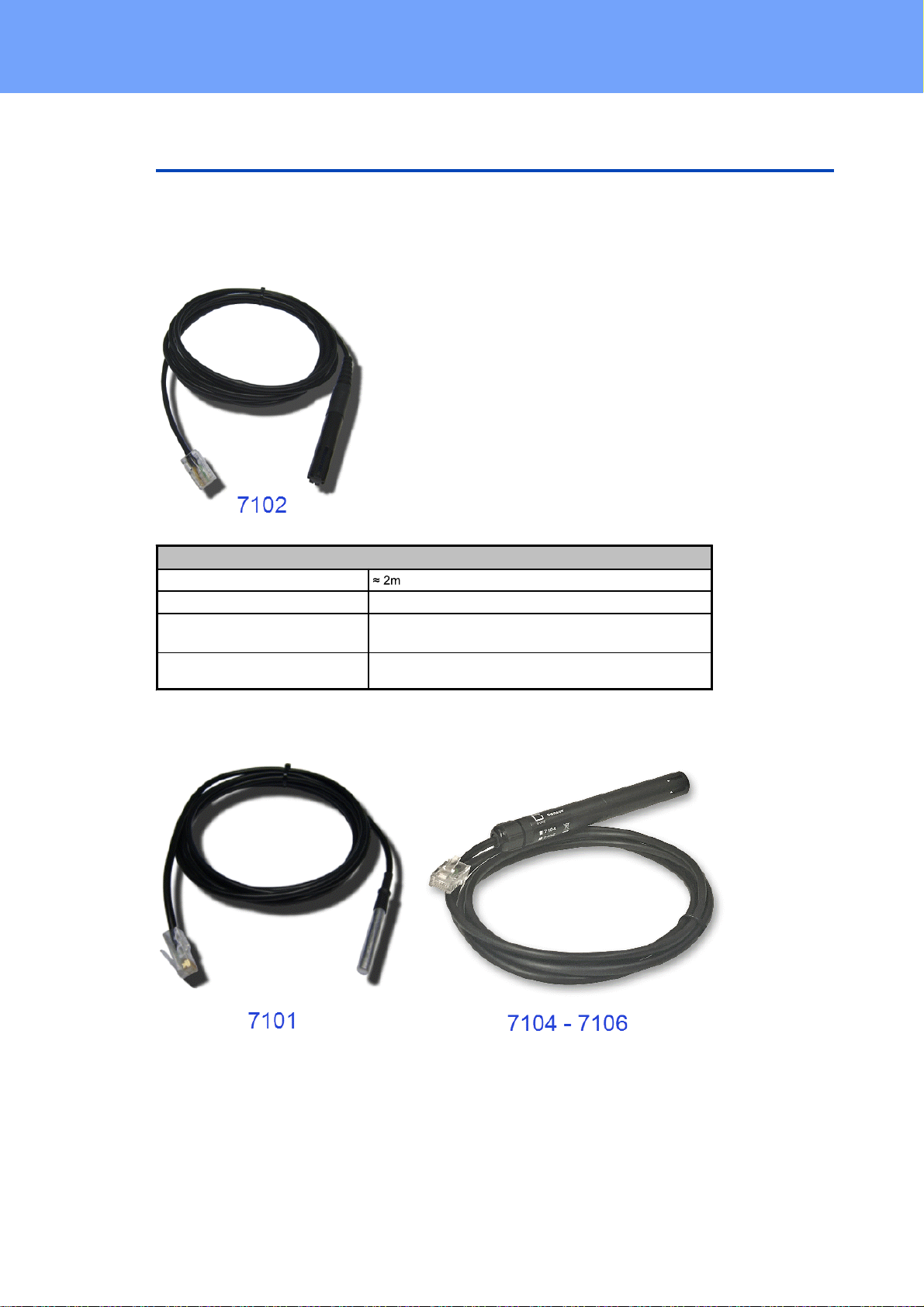
Humidity/Temperature Sensor 7102 (End-of-Life)
Cable length
Connector
RJ45
temperature range
-20°C to +80°C, ±0,5°C (maximum) and ±0,3°C (typical)
air humidity range
(non-condensing))
0-100%, ±3% (maximum) and ±2% (typical)
1.7 Sensor
Four external sensors can be connected to the Expert Net Control 2111 / 2191. The
following sensors are currently available
Expert Net Control 2111/2191 © 2021 GUDE Systems GmbH
12
Device Description
Product Name
7101
7104-1
7105-1
7106-1
Calibrated
Sensor
-
7104-2
7105-2
7106-2
Cable length
Connector
RJ45
RJ45
RJ45
RJ45
temperature range
-20°C to +80°C at
±2°C (maximum)
and ±1°C (typical)
-20°C to +80°C at
±2°C (maximum)
and ±1°C (typical)
-20°C to +80°C at
±2°C (maximum)
and ±1°C (typical)
-20°C to +80°C at
±2°C (maximum)
and ±1°C (typical)
air humidity range
(non-condensing)
-- 0-100%, ±3%
(maximum) and
±2% (typical)
0-100%, ±3%
(maximum) and
±2% (typical)
air pressure range
(full)
---
± 1 hPa (typical)
at 300 ... 1100
hPa, 0 ... +40 °C
air pressure range
(ext)
---
± 1.7 hPa (typical)
at 300 ... 1100
hPa, -20 ... 0 °C
Protection
IP68--
-
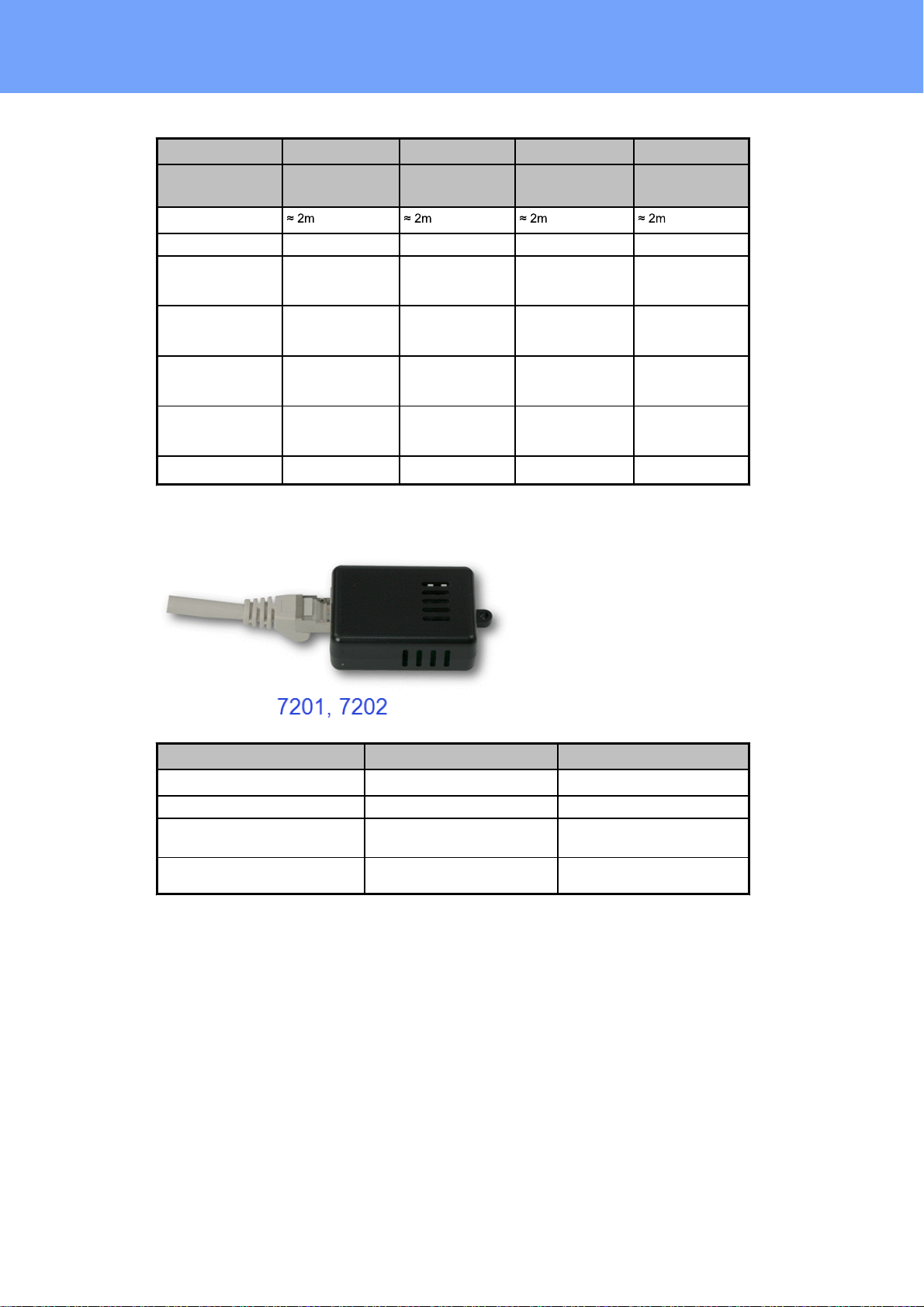
Product Name
7201
7202
Cable length
-
-
Connector
RJ45
RJ45
temperature range
-20°C to +80°C at ±2°C (maximum) and ±1°C (typical)
-20°C to +80°C at ±2°C (maximum) and ±1°C (typical)
air humidity range
(non-condensing)
-
0-100%, ±3% (maximum) and
±2% (typical)
13
Expert Net Control 2111/2191 © 2021 GUDE Systems GmbH
Device Description
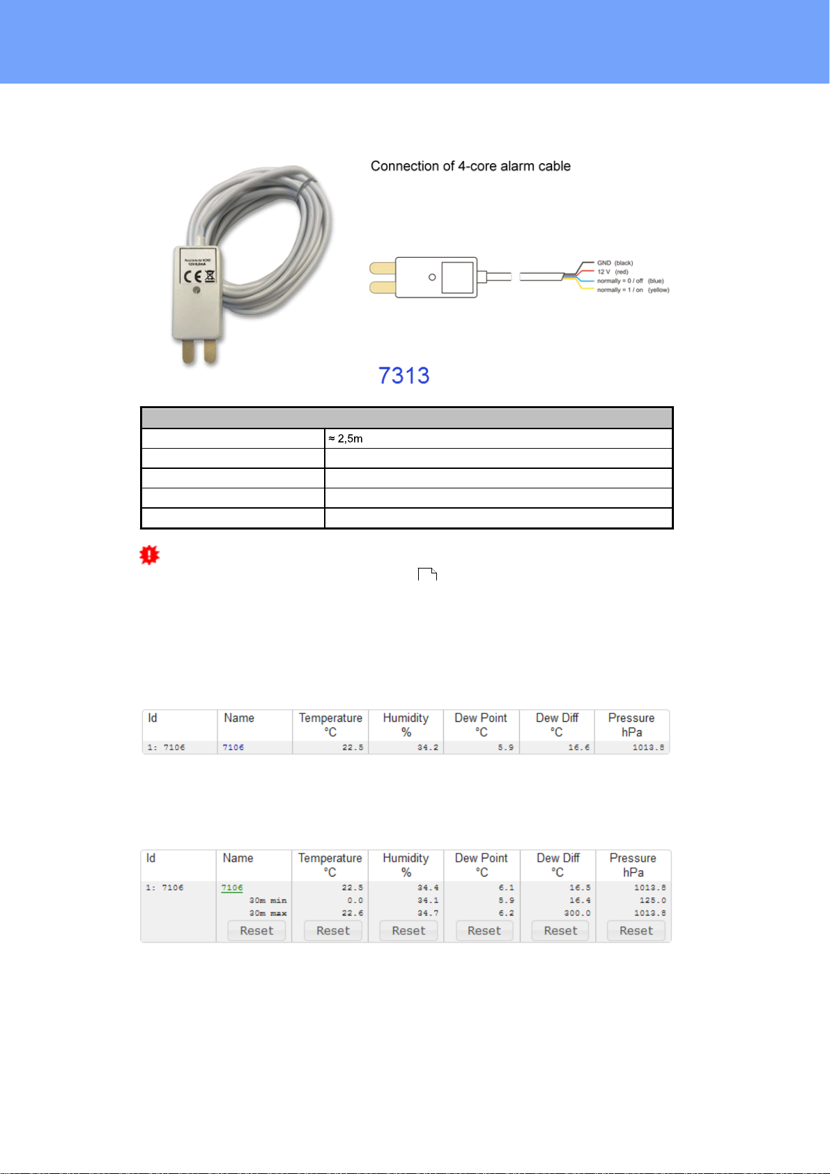
Leakage Point Sensor 7313
Cable length
Connector
4-wire cable
operating temperature
-10 °C - 40 °C
operating voltage
12 V DC
Output
max. 200 mA
For the connected leakage point sensor 7313 to work, the 12 V power supply
must be activated in the sensor configuration .
61
The sensors are detected automatically after connection. The green LED on the
RJ45 sensor connector then lights up permanently. If the sensor value is displayed permanently on the display, the green LED flashes. The sensor values
are displayed directly on the "Control Panel" website:
A click on the link in the "Name" column opens the display of the Min and Max values.
The values in a column can be reset using the "Reset" button. The "Reset" button in
the name column deletes all stored Min and Max values.
Expert Net Control 2111/2191 © 2021 GUDE Systems GmbH
14

Operating
Operating
2 Operating
2.1 Operating the device directly
Port Switching
The current status of the output is indicated by the color of the LED. Red indicates that
the output is off, green shows that the output is on. On the device are the buttons "se-
lect" and "ok". If you press "select", you can select the following modes one by one:
1. At first, all LEDs flash green. If you press the "Ok" button for 4 seconds, all ports
are switched on. (If all ports are switched on, this is skipped).
2. After that, all LEDs flash red. If you hold the "Ok" button for 4 seconds, all ports will
be switched off. (If all ports are switched off, this will be skipped).
3. If you press "Select" again, the LED for the first output starts blinking, i.e. the output
is selected. Press "Select" again to select the next output. If you keep the "Ok" button pressed for one second, the state of the selected output will be toggled.
You can switch off in the front panel configuration that all ports with the modes 1 and 2
can be switched by pushbutton.
Display Information
If no port is selected manually, repeatedly pressing the "ok" key will show the IP-address and the values of the external sensors on the display.
Status-LED
The Status LED shows the different states of the device:
· red: The device is not connected to the Ethernet.
· orange: The device is connected to the Ethernet and waits for data from the DHCP
server.
16
Expert Net Control 2111/2191 © 2021 GUDE Systems GmbH
Operating
· green: The device is connected to the Ethernet and the TCP/IP settings are allocated.
· periodic blinking: The device is in Bootloader mode.
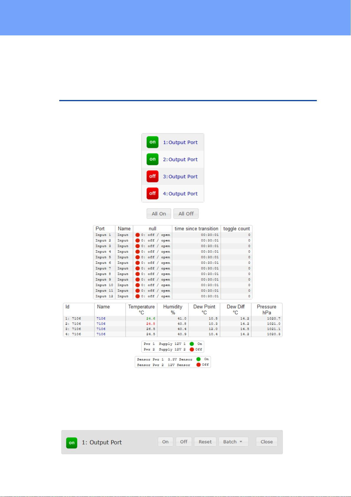
2.2 Control Panel
Access the web interface: http://"IP-address" and log-in.
The web page provides an overview of the switching state, energy measurement values, as well as the external sensors, provided that they are connected. When a single
port is clicked at the Expert Net Control 2111 / 2191, a panel with buttons to control a
single port appear:
17
Expert Net Control 2111/2191 © 2021 GUDE Systems GmbH
Operating
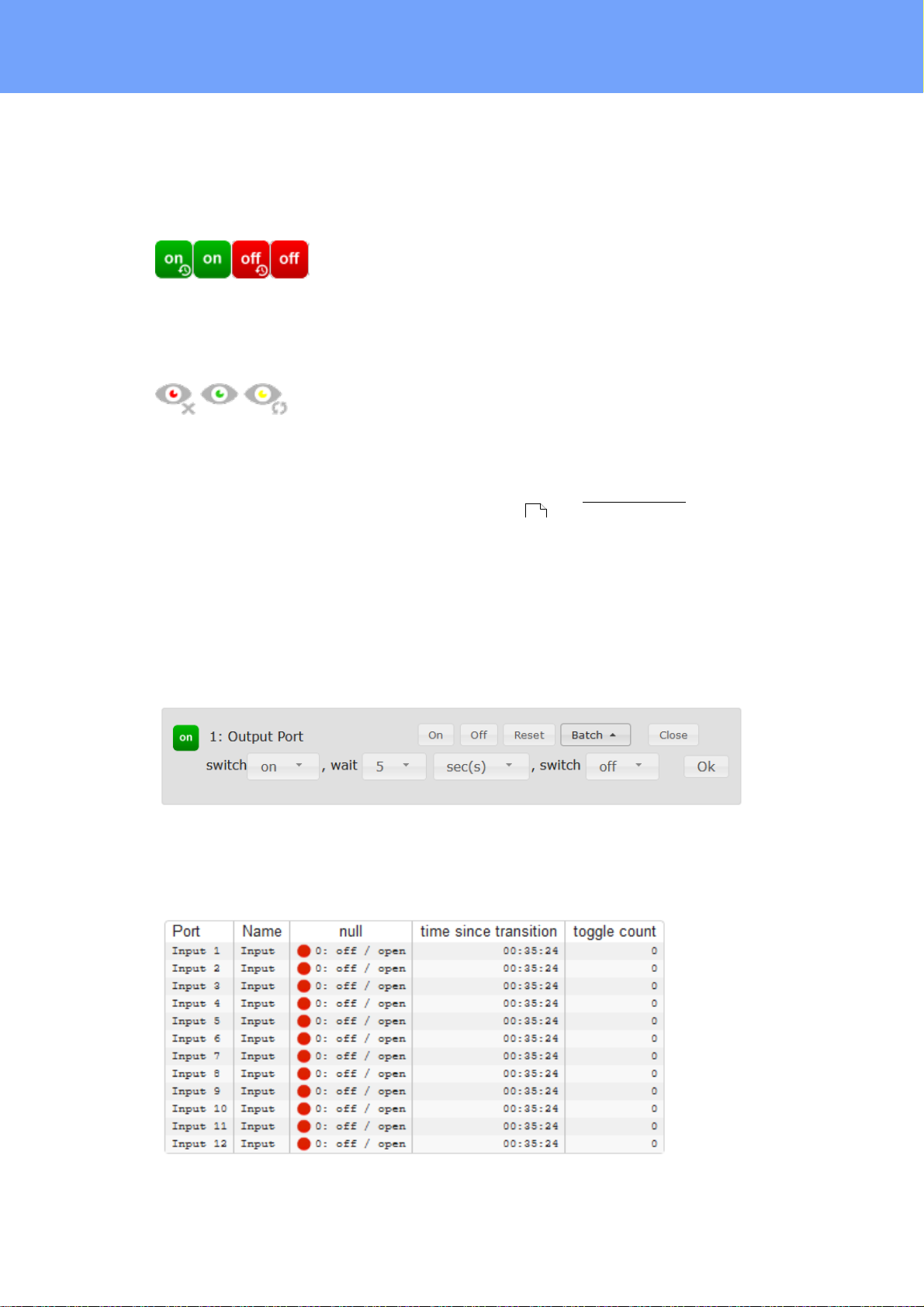
The Port icon is green when the relay is closed, or red in the open state. An additional
small clock icon indicates that a timer is active. Timer can be activated by delay, reset
or batch mode.
An activated Watchdog is represented by an eye icon. An "X" means, that the address
that should be observed, could not be resolved. Two circular arrows show a booting
status.
The ports can be switched manually with the "On" and "Off" buttons. If the port is
turned on, it can be turned off by pressing the "Reset" button, until after a delay it turns
itself on again. The delay time is determined by the parameter Reset Duration, which is
described in the chapter "Configuration - Output Ports ". The "Close" button dissolves the panel again.
39
Batchmode
Each individual port can be set for a selectable period of time to the state "switch on"
or "switch off". After the selected time they are automatically switched to the second
preselected state.
Optionally the device can be switched via a Perl script or external tools like wget. More
information is available on our support wiki at www.gude.info/wiki.
18
Expert Net Control 2111/2191 © 2021 GUDE Systems GmbH
Operating
The website contains a status overview of all passive signal inputs, the time since the
last change, and a counter of switching changes. The name and text for a logical state
of each input can be configured in the chapter Configuration-Input Ports .
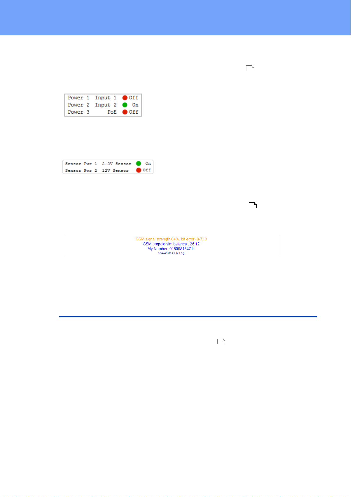
This table shows which voltage inputs (Pwr1 to Pwr3) are connected to a power supply
or if Power-over-Ethernet (PoE) is active.
The indicator "3.3V sensor" shows whether the 3.3 V supply of the electronics of the
external sensors works, which can be connected via RJ45. The "12V sensor" display
indicates whether 12 V voltage is available at the external sensors or the passive signal inputs. The 12 V supply can be switched on in Configuration-Sensors .
42
61
For devices with a GSM module (Expert Net Control 2191), additional reception information, the prepaid credit and the own call number are displayed. An overview of
the GSM activities can be expanded.
2.3 Maintenance
The actual device generation with IPv6 and SSL allows all maintenance functions in
the web interface to be carried out on the Maintenance Page .
Maintenance in the web interface
The following functions are available from the maintenance web page:
· Firmware Update
· Change the SSL certificate
· Load and save the configuration
· Restart the device
· Factory Reset
· Jump into the Bootloader
· Delete the DNS cache
21
Upload Firmware, Certificate or Configuration
19
Expert Net Control 2111/2191 © 2021 GUDE Systems GmbH

Operating
On the Maintenance Page , select the required file with "Browse .." in the sections
21
"Firmware Update", "SSL Certificate Upload" or "Config Import File Upload" and press
"Upload". The file is now transferred to the update area of the device and the contents
are checked. Only now, pressing the "Apply" button will permanently update the data,
or abort with "Cancel".
Only one upload function can be initiated with a reboot, eg. you cannot transmit
firmware and configuration at the same time.
If after a firmware update, the web page is not displayed correctly anymore, this
may be related to the interaction of Javascript with an outdated browser cache. If a
Ctrl-F5 does not help, it is recommended that you manually delete the cache in the
browser options. Alternatively, you can test start the browser in "private mode".
During a firmware update, old data formats are sometimes converted to new structures. If an older firmware is newly installed, the configuration data and the energy
meters may be lost! If the device then does not run correctly, please restore the factory
settings (e.g. from the Maintenance Page ).
21
Actions in Bootloader mode
If the web interface of the device is no longer accessible, the device can be put into
Bootloader mode (see chapter Bootloader activation ). The following functions can
be executed using the GBL_Conf.exe application:
24
· Set IPv4 address, net-mask and gateway
· Turn HTTP password on and off
· Turn IP-ACL on and off
· Factory Reset
· Jump into the bootloader (can be switched on and off)
· Restart the device
For devices with relays, entering or exiting the bootloader mode does not change
the state of the relays as long as the operating voltage is maintained.
The GBL_Conf.exe program is available free of charge on our website www.gude.info
and can also be found on the enclosed CD-ROM.
20
Expert Net Control 2111/2191 © 2021 GUDE Systems GmbH
Operating
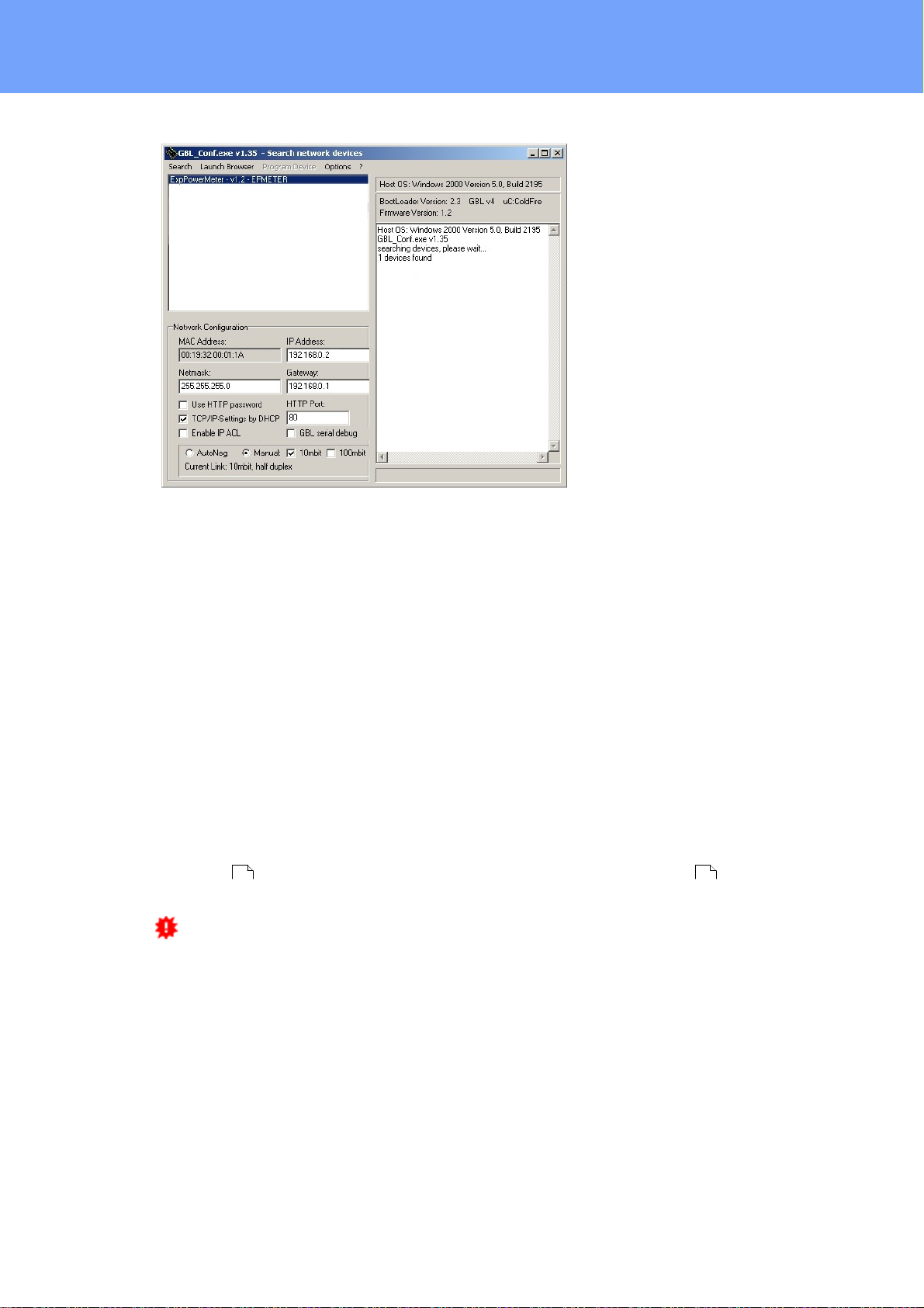
Interface GBL_Conf
To check the network settings with GBL_Conf.exe, start the program and choose "All
Devices" in the "Search" menu. From the list select the appropriate device. The lower
part of the left half of the window now shows the current network settings of the device.
If the IP address is displayed with the default settings (192.168.0.2), either no DHCP
server is present on the network, or there could be no free IP address assigned to it.
· Activate the Bootloader Mode (see Chapter Bootloader Mode) and choose in menu
"Search" the item "Bootloader-Mode Devices only"
· Enter the desired settings in the edit window and save them with "Save Config".
· Deactivate the boot loader mode for the changes to take effect. Select again "All
Devices" in the "Search" menu of GBL_Conf.exe.
The new network configuration is now displayed.
Factory Reset
The device can be reset to the factory default via the web interface from the Maintenance Page or from the Bootloader mode (see chapter Bootloader activation ). All
TCP/IP settings are reset in this operation.
If a unit is set to factory defaults, an uploaded certificate or updated firmware will
be preserved.
21 24
2.3.1
Maintenance Page
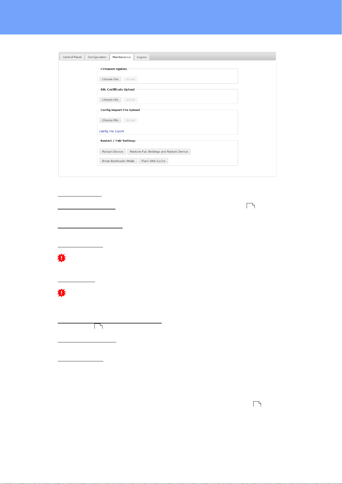
This section provides access to important functions such as Firmware Update or Restart Device. It is advisable to set an HTTP password for this reason.
21
Expert Net Control 2111/2191 © 2021 GUDE Systems GmbH
Operating
Firmware Update: Start a firmware update.
SSL Certificate Upload: Saves your own SSL certificate. See chapter "SSL " for the
generation of a certificate in the right format.
Config Import File Upload: Loads a new configuration from a text file. To apply the new
configuration, a "Restart Device" must be executed after the "Upload".
Config File Export: Saves the current configuration in a text file.
Saving the configuration should only be carried out in an SSL connection, since it
contains sensitive password information (even if it is encrypted or hashed).
Restart Device: Restarts the device without changing the status of the relays.
Some functions such as a firmware update or changing of the IP-address and
HTTP settings require a restart of the device. A jump to the boot loader or a restart of
the device lead by no means to a change of the relay states.
Restore Fab Settings and Restart Device: Performs a restart and resets the device to
factory default .
Enter Bootloader Mode: Jumps into bootloader mode, where additional settings can be
made with GBL_Conf.exe.
Flush DNS Cache: All entries in the DNS cache are discarded and address resolutions
are requested again.
25
77
2.3.2
Configuration Management
The device configuration can be saved and restored in the maintenance area .
21
22
Expert Net Control 2111/2191 © 2021 GUDE Systems GmbH

Operating
The "Config File Export" function can be used to save the current configuration as a
text file. The syntax used in the configuration file corresponds to the commands of the
Telnet console. If the configuration of a device is to be restored from a text file, load
the file with "Upload" and restart the device with "Restart Device".
Saving the configuration should only be carried out in an SSL connection, since it
contains sensitive password information (even if it is encrypted or hashed). For the
same reasons, it is advisable to carefully handle the generated configuration files when
archiving.
Editing the configuration file
It is possible to customize a saved configuration file with a text editor for your own
needs. For example, one scenario would be to use a script language to automate the
creation of many customized versions of a configuration, then equip a large number of
devices with an individualized configuration. Also Upload and restart with CGI commands can be done in scripting languages. With use of the comment sign "#" you can
quickly hide single commands or add personal notes.
If you modify a configuration file manually, it is not always clear which limits are allowed
for parameters. After uploading and restarting, commands with invalid parameters are
ignored. Therefore, the generated configuration includes comments describing the
boundaries of the parameters. Where "range:" refers to a numeric value, and "len:" to a
text parameter. E.g:
email auth set 0 #range: 0..2
email user set "" #len: 0..100
The command "system fabsettings" from the beginning of a generated configuration
file brings the device into the factory state, and then executes the individual commands
that modify the configuration state. It may be desirable to make the changes relative to
the current configuration, and not out of the factory state. Then the "system fabsettings" should be removed.
No output of default values
The configuration file contains (with exceptions) only values which differ from the default. The command "system fabsettings" (go to the factory state) from the beginning of
a generated configuration file should not be removed, otherwise the device can get incompletely configured.
Configuration via Telnet
The configuration files can in principle also be transferred in a Telnet session, but then
the settings are changed during operation, and not completely when restarting, as it
would have been the case with an upload. It can happen that events are triggered at
the same time as the device is configured. One should therefore:
a) disable the function
b) completely parametrize
23
Expert Net Control 2111/2191 © 2021 GUDE Systems GmbH

Operating
c) reactivate the function
An example:
email enabled set 0
email sender set "" #len: 0..100
email recipient set "" #len: 0..100
email server set "" #len: 0..100
email port set 25
email security set 0 #range: 0..2
email auth set 0 #range: 0..2
email user set "" #len: 0..100
email passwd hash set "" #len: 0..100
email enabled set 1 #range: 0..1
2.3.3
Bootloader Activation
The configuration of the device from the application "GBL_Conf.exe" is only possible, if
the device is in Bootloader Mode.
Activation of the Bootloader Mode
1) via push button:
· Hold both buttons for 3 seconds
2) or
· Remove the power supply
· Hold down the "Select" button. If the push button is recessed, use a pin or paper clip
· Connect the operating voltage
3) by Software: (only if "Enable FW to BL" was previously activated in the
"GBL_Conf.exe" application)
· Start the "GBL_Conf.exe" program
· Do a network search with the "Search" menu action
· Activate in menu "Program Device" the item "Enter Bootloader"
4) via web interface:
Press "Enter Bootloader Mode" on the maintenance web page.
Whether the device is in Bootloader mode, is indicated by the flashing of the status
LED, or it is shown in "GBL_Conf.exe" application after a renewed device search (appendix "BOOT-LDR" after the device name). In Bootloader mode the program
"GBL_Conf.exe" can disable the password and the IP ACL, perform a firmware update,
and restore the factory settings.
For devices with relays, entering or exiting the bootloader mode does not change
the state of the relays as long as the operating voltage is maintained.
21
Abandonment of the Bootloader Mode
1) via push button:
24
Expert Net Control 2111/2191 © 2021 GUDE Systems GmbH

Operating
· Hold both buttons for 3 seconds (only if the device has 2 buttons)
2) or
· Remove and connect the power supply without operating a button
3) by Software:
· Start the "GBL_Conf.exe" application
· Do a network search with the "Search" menu action
· In menu "Program Device" activate the item "Enter Firmware"
Factory Reset
If the device is in bootloader mode, it can always be put back to its factory default. All
TCP/IP settings are reset in this operation.
If a unit is set to factory defaults, an uploaded certificate or updated firmware will
be preserved.
1) via push button:
· Activate the Bootloader Mode of the device
· Hold down the button (or the "Select" button for devices with 2 buttons) for 6
seconds. If the push button is recessed, use a pin or paper clip
· The status LED will blink in a fast rhythm, please wait until the LED blinks slowly
(about 5 seconds)
2) by Software:
· Activate the Bootloader Mode of the device
· "Start the GBL_Conf.exe" program
· In menu "Program Device" activate the item "Reset to Fab Settings"
· The status LED will blink in a fast rhythm, please wait until the LED blinks slowly
(about 5 seconds)
2.4 GSM
To use the GSM functions, there must be an activated SIM card in the SIM card slot.
If the SIM card is inserted, and the device is enabled, the integrated GSM module
searches automatically for a connection to the GSM network. If this connection works,
you can control and configure the device via SMS or by call.
When operating via SMS, send defined SMS commands to the device. The device executes these commands and confirms them with reply SMS.
When operating via phone call, you can perform commands by FreeCall, that allow the
unit to perform preconfigured commands, when it is called from a particular phone
number. There is no connection established and there are no call charges. Another
possibility is the voice call. Here, the device menu is operated using DTMF codes. This
type of operation can also be carried out automatically.
Preparing for GSM operation
25
Expert Net Control 2111/2191 © 2021 GUDE Systems GmbH

Operating
If you are using a new SIM card, please take note:
1. Preparing the SIM card
2. SIM-card pin code
3. Install SIM card
· If you are using a contracted SIM card, please start with step 2
· If you are using a prepaid SIM card, please take care:
o There has to be a positiv balance on the card
o The card has to be activated. New prepaid cards need some
manual operation at the start of usage. These requests have to be
made from a user with a cellphone.
· The device awaits the SIM card pin code 1234 first. Enter this PIN to the
SIM card, by using a cellphone. In case you are using another pin code,
you have to configure the EPC NET GSM before you activate the GSM
part of the device! Otherwise this may lead to a lock of the SIM card.
· You can disable the need to enter the PIN code on the SIM card with a
mobile phone. In this case the EPC NET GSM accepts the SIM card
without checking the code.
· Switch off the device or deactivate the GSM module. Alternatively, you
can just turn off the GSM module in the EPC NET GSM via software.
Never install a SIM card, when GSM module is active. Otherwise the
SIM card may be destroyed.
· Insert the SIM card into the Push Sim Holder.
4. Connect Antenna
· Take the GSM antenna from the box and screw it to the EPC NET GSM
by turning clockwise. It is enough to attract the connection hand-tight.
Never use pliers to tighten or similar to the antenna, thus inevitably destroying the antenna connection.
5. Activate the EPC NET GSM
· Power up the device. In factory default state, the GSM module is deactivated. This is a security setting in delivery to avoid accidentally locking
a SIM card with the wrong code.
· Log in on the web interface.
· Switch to Configuration / GSM / SIM.
· Here the button "Enable GSM" is set to "No", that is the GSM module is
turned off. Set the button to "yes", then press the button "Apply" to transmit the data to the EPC NET GSM.
· Wait some minutes, until the device has logged into the GSM. You can
see the status change from the Signal Tower indicator LED on the display or in the web interface.
GSM Status LED's
The GSM status LED's displays different states of the GSM module.
Signal Tower indicator off
GSM module is deactivated.
Signal Tower indicator on
GSM module activated.
Signal Strength Indicator
· 0 bars - no signal
· 2 bars - approx. 30%
26
Expert Net Control 2111/2191 © 2021 GUDE Systems GmbH

Operating
· 4 bars - approx. 70%
· 6 bars - approx. 100%
2.4.1
2.4.1.1
SMS
SMS Commands
Description of the SMS format to send commands to the device:
Format
%[cmd-name] [param 1] [...] [param N] {param 1} {...} {param N}
[param x] = mandatory parameter
{param x} = optional paramater
If activated, a port code or master code will be required. Entering these codes is initiated by p (for Port code) or m (for Master code).
2.4.1.1.1 Port: Query Port State
Format
%port state [portnumber] {Portcode/Mastercode}
Command:
Request of status of Output Port 1, Portcode 1111
%port state 1 p1111
Answer:
Hostname: ENC-2191
Output Port state: Port 1 is Off
Credit: 130.50 Eur
2.4.1.1.2 Port: Simple Switching
Format
%port [on, off, toggle] [portnumber] {Portcode/Mastercode}
Examples:
Switch off Output Port 2, Mastercode 2222
%port off 2 m2222
Toggle Output Port 8, Portcode 1238
%port toggle 8 p1238
Reset Output Port 6, Portcode 0123
%port reset 6 p0123
Switch on Output Port 1, without Portcode
%port on 1
Answer (example):
Device name: epc007
Port switch: Port 1 off -> on
27
Expert Net Control 2111/2191 © 2021 GUDE Systems GmbH

Operating
tn
Time in seconds
t11t22t35t410t520t660t7
120t8240t9480
Account Credit: Credit: 130.50 Eur
2.4.1.1.3 Port: Advanced Switching (Batchmode)
Format
%port batchmode [portnumber] [batch-sequence-number] {Portcode/Mastercode}
[batch-sequence-number]
'11' .. '19' off, wait [t1 .. t9]s, on
'21' .. '29' on, wait [t1 .. t9]s, off
'31' .. '39' toggle, wait [t1 .. t9]s, toggle
Note: Sequence numbers are identical to the DTMF codes for voice calls.
Example:
%port batchmode 1 13 m0123
Answer:
Device name: epc007
Switch sequence: Port 1 off -> t3 -> on
Account Credit: Credit 130.50
2.4.1.1.4 Port: Advanced Switching (coldstart)
The command 'coldstart' turns off all Output Ports at once. Then it switches the ports
temporally delayed on again (according to the current output port configuration), as if
the device performs a cold start.
Format
%coldstart {mastercode}
Example:
%coldstart m0123
Answer:
Device name: epc007
Switch sequence: coldstart
Account Credit: Credit: 130.50 Eur
Expert Net Control 2111/2191 © 2021 GUDE Systems GmbH
28

Operating
2.4.1.1.5 Configuration: Read
Format
%config get [config-name] {mastercode}
[config-name ]:
Example:
%config get code m1234
Example:
%config get all
30
all
code
telbook
gsmstatus
response
error
portname
adminnum
gsm
Answer:
Config: code = on
Answer:
Config: code = on
telbook = off
[...]
adminnum = 0161123456
gsm = on
2.4.1.1.6 Configuration: Write
Format
%config set [config-name] [config-value] {Mastercode}
[config-name] :
code
telbook
gsmstatus
response
error
portname
adminnum
gsm
Example:
%config set code off m1234
Answer:
Config: code = off
30
29
Expert Net Control 2111/2191 © 2021 GUDE Systems GmbH

Operating
Description
SMS [config-name]
SMS [config-value]
default
Master/Port
Code enabled?
code
on, off
off
Check of phone
book?
telbook
on, off
off
Send GSM
Status SMS to
'adminnum'
gsmstatus
on, off
off
Send SMS reply
on SMS commands to recent
SMS user
response
on, off
on
Send SMS reply
with error message, if SMS
command was
malformed
error
on, off
on
States configured Port
name instead of
Output Port n in
SMS replies
portname
on, off
off
Allow deactivation of GSM
module via SMS
gsm
on, off
off
Phone number
for e-mail messages
email
max. 15 chars
Access only for
admin
mastergsm
on, off
off
Autosync
autosync
on, off
off
DTMF for
VoiceCall
calltone
on, off
off
Voice for
VoiceCall
callvoice
on, off
on
Phone number
for SMS messages
adminnum
max. 15 chars
Allows freecall
operation
freecall
on, off
off
2.4.1.1.7 Configuration: All Parameter
2.4.1.1.8 Sensors: Query State
Expert Net Control 2111/2191 © 2021 GUDE Systems GmbH
Format
%sensor state [portnumber, all] {Mastercode}
Example:
Query the state of all sensors, Mastercode 0000
30

Operating
Device name: [name]
prefix
[response text]
Command specific reply
Account credit: [x]
%sensor state m0000
Answer:
Device name: epc007
Port: Sensor port 1
Sensor name: Temperature
Value: NC
Port: Sensor port 2
Sensor name: Temperature
Value: T=22.79C
Value: RH= 76.64%
Account credit: Credit: 130.50 Eur
2.4.1.1.9 Query Device State
Format
%all state {Mastercode}
Example:
Query the state of the device:
%all state
Answer:
Device name: epc007: Status
Outputport state: outp: 1=On 2=On 3=On 4=Off
Inputport state: dinp: 1=Off 2=Off 3=Off 4=Off
Account credit: Credit: 130.50 Eur
2.4.1.2
SMS replies
2.4.1.2.1 SMS command replies
A command reply SMS looks like:
[response text]
Device name: [name]
Port switch: [port] [s] -> [s]
[port] = Port 1 .. Port 99 (or Config:portname)
[s] = on .. off
Port state: [port] is [s], [...], [port] is [s]
[port] = Port 1 .. Port 99 (or Config:portname)
[s] = on .. off
Switch sequence: [s]
[s]
[port] [c] -> wait t -> [c]
[port] = 'Port 1' .. 'Port 99' (or Config:portname)
31
Expert Net Control 2111/2191 © 2021 GUDE Systems GmbH

Operating
Device name: [name]
Prefix
[response text]
Status change request specific reply
Account credit: [x]
Numbers
Men
*1#
Output Port
*2#
Input Port
*8#
Status
[c] = on, off, toggle, coldstart
Account credit: [x]
Config: name = value, [...], name = value
or
command parse error
2.4.1.2.2 Status Change Report SMS
A SMS status change request reply looks like:
[response text]
2.4.2
2.4.2.1
Device name: [name]
[port] -> [s]
[port] = 'Port 1' .. 'Port 99' (or Config:portname)
[s] = 'on' .. 'off'
[port] [s]
[port] = 'Port 1' .. 'Port 99' (or Config:portname)
[s] = batchmode, toggled, Coldstart
Temperature state: [val]
[val] = 'over the MAX limit', 'under the MIN limit'
Account credit: [x]
Voice Call
Menu
For operating with VoiceCall, simply call the phone number of the SIM card of the GSM
module. When connection is established the device replies with the announcement:
"Main menu" and a DTMF tone
In the menu the navigation works via DTMF commands.
Each command starts with # and ends with *.
Expert Net Control 2111/2191 © 2021 GUDE Systems GmbH
32

Operating
You can combine multiple commands into a command. Just type the commands one
after another and terminate it as a whole with #.
*[Command 1][Command 2]...[Command n]#
Some commands may require the Port or MasterCode. These codes have to be added
at end of the command
Eample:
Navigate from Main Menu into the Status Menu using mastercode 1111
*8# - enter Status Menu
1111 - Mastercode
For the navigation in menus the following commands are required:
*99# - Jump to Main Menu
*98# - Return to prev Menu
*97# - Help
2.4.2.1.1 Port Menu
Here you can choose and switch Output Ports or request the status of a Output Port.
Example:
*1# - Switch to Output Port menu
*5# - Choose Output Port 5
*01# - Switch on
Or connected into one command: *1501#
For devices with more than 9 power ports, the port numbers must be entered with
two digits. The previous command would then look like this: *10501#
Example:
*7# - Choose Output Port 7
*23# - Activate Batchmode No.23 for Output Port 7 - Output Portt 7 on, wait t3, off
Example:
*3# - Choose Output Port 3
*03# - Request state of Output Port 4
Or as one command: *303#
Please check the Output Port commands [pc] for further information
33
Expert Net Control 2111/2191 © 2021 GUDE Systems GmbH

Operating
*00#
Value of the account of the PrePaid card
*01#
Request of an SMS with all output port information, announcement
"SMS sent"
*03#
Request of an SMS with configuration information, announcement
"SMS sent"
*04#
Request of actual sensor information (a sensor has to be connected)
*10#
Request of the state of all Output Ports
Port Command
Command
Description
00
off
Switch off
2.4.2.1.2 Status Menu
Different states of the device can be requested
2.4.2.1.3 Parameter Description
[pn]
Output Port Number
- Values: '1' .. '9'
For devices with more than 9 power ports, the port numbers must be entered with
two digits - Values: '01' .. '99'
[ps]
- Output Port State
- Values: '0' .. '1'
(on/off)
[pc]
- Output Port Command
- Values: '00' .. '89'
[in]
- Input-Port Number
- Values: '1' .. '9'
[is]
- Input-Port State
- Values: '0' .. '1'
(on/off)
[sq]
- Status Query
- Values '01' .. '89'
Special Menu Commands (90 .. 00)
- 99 : Jump to Main Menu
- 98 : return to prev Menu
2.4.3
Expert Net Control 2111/2191 © 2021 GUDE Systems GmbH
Port Commands
List of possible Output Port commands (pc)
34

Operating
Port Command
Command
Description
01onSwitch on
02
toggle
Toggle
03
state info
Request of state of Port
04
reset
Switch off, wait 30 seconds, switch on
Port Command
Command
Description
11
Batchmode: off,
wait t1, on
Port off, wait t1, Port on
12
Batchmode: off,
wait t2, on
Port off, wait t2, Port on
13
Batchmode: off,
wait t3, on
Port off, wait t3, Port on
14
Batchmode: off,
wait t4, on
Port off, wait t4, Port on
15
Batchmode: off,
wait t5, on
Port off, wait t5, Port on
16
Batchmode: off,
wait t6, on
Port off, wait t6, Port on
17
Batchmode: off,
wait t7, on
Port off, wait t7, Port on
18
Batchmode: off,
wait t8, on
Port off, wait t8, Port on
19
Batchmode: off,
wait t9, on
Port off, wait t9, Port on
Port Command
Command
Description
21
Batchmode: on,
wait t1, off
Port on, wait t1, Port off
22
Batchmode: on,
wait t2, off
Port on, wait t2, Port off
23
Batchmode: on,
wait t3, off
Port on, wait t3, Port off
24
Batchmode: on,
wait t4, off
Port on, wait t4, Port off
25
Batchmode: on,
wait t5, off
Port on, wait t5, Port off
26
Batchmode: on,
wait t6, off
Port on, wait t6, Port off
27
Batchmode: on,
wait t7, off
Port on, wait t7, Port off
28
Batchmode: on,
wait t8, off
Port on, wait t8, Port off
29
Batchmode: on,
wait t9, off
Port on, wait t9, Port off
35
Expert Net Control 2111/2191 © 2021 GUDE Systems GmbH

Operating
Port Command
Command
Description
31
Batchmode:
toggle,
wait t1, toggle
Port toggle, wait t1, Port toggle
32
Batchmode:
toggle,
wait t2, toggle
Port toggle, wait t2, Port toggle
33
Batchmode:
toggle,
wait t3, toggle
Port toggle, wait t3, Port toggle
34
Batchmode:
toggle,
wait t4, toggle
Port toggle, wait t4, Port toggle
35
Batchmode:
toggle,
wait t5, toggle
Port toggle, wait t5, Port toggle
36
Batchmode:
toggle,
wait t6, toggle
Port toggle, wait t6, Port toggle
37
Batchmode:
toggle,
wait t7,toggle
Port toggle, wait t7, Port toggle
38
Batchmode:
toggle,
wait t8, toggle
Port toggle, wait t8, Port toggle
39
Batchmode:
toggle,
wait t9, toggle
Port toggle, wait t91, Port toggle
tn
Time in seconds
t11t22t35t410t520t660t7
120t8240t9480
2.4.4
Expert Net Control 2111/2191 © 2021 GUDE Systems GmbH
Security
Please note that the device has no security options set in the delivery settings, in order
to allow a quick start. For a later use we strongly recommend that you activate the
phone book check and code queries. The phone book check provides pretty high security, because only phone book members can operate the device. Unfortunately, there
are mobile carriers that allow to simulate any number with some technical effort. These
numbers will be marked with a special bit and can only be identified by the police as
forged. Unfortunately the GSM network has no possibility to identify this fake numbers.
36

Operating
Access
Phonebook
Check
Port/Maste
rCode
Security
Anybody
off
off
Very low
Phonebook Check
on
off
Normal
Code Check
offonHigh
Phonebook and
Code Check
on
on
Very high
For this reason we recommend the code query.
37
Expert Net Control 2111/2191 © 2021 GUDE Systems GmbH

Configuration

Configuration
3 Configuration
TCP/IP configuration by DHCP
After switching on the device is scanning on the Ethernet for a DHCP server and requests an unused IP address. Check the IP address that has been assigned and adjust if necessary, that the same IP address is used at each restart. To turn off DHCP
use the software GBL_Conf.exe or use the configuration via the web interface.
To check the network settings with GBL_Conf.exe, start the program and choose "All
Devices" in the "Search" menu. From the list select the appropriate device. The lower
part of the left half of the window now shows the current network settings of the device.
If the IP address is displayed with the default settings (192.168.0.2), either no DHCP
server is present on the network, or there could be no free IP address assigned to it.
3.1 Output Ports
39
Choose Output Port to configure: This field is used to select the Output Ports to be
configured.
Label: You can assign a name up to 15 characters for each of the Output Ports. Using
the name, an identification of the the device connected to the port can be facilitated.
Start-up Monitoring
It is important, that if necessary the condition of the Output Ports can be restored after
a power failure. Therefore each port can be configured with Initialization status to a
specific start-up state. This start-up sequence can be carried out delayed by the parameter Initialization Delay. There is in any case a minimum one-second delay between
switching of ports.
Initialization status(coldstart): This is the port state (on, off, remember last state) the
port should be set when the device is turned on. The setting "remember last state"
saves the last manually set state of the Output Port in the EEPROM.
Initialization delay: Here can be configured how long the port should wait to switch to its
defined state after the device is turned on. The delay may last up to 8191 seconds.
This corresponds to a period of approx. two hours and 20 minutes. A value of zero
means that the initialization is off.
Expert Net Control 2111/2191 © 2021 GUDE Systems GmbH

Configuration
GSM Portcode (only ENC 2191): Sets the individual port access code.
Repower delay: When this feature is enabled (value greater than 0), the Output Port
will switch itself on again a specified time after it has been disabled. Unlike the "Reset"
button this function applies to all switch actions, including SNMP, or an optional serial
interface.
Reset Duration: When the "Reset" button is triggered, the device turns the Output Port
off, waits for the time entered here (in seconds) and turns the Output Port on.
3.1.1
Watchdog
The watchdog feature enables to monitor various remote devices. Therefore either
ICMP pings or TCP pings are sent to the device to be monitored. If these pings are not
answered within a certain time (both the time and the number of attempts can be set),
the port is reset. This allows e.g. to automatically restart not responding server or NAS
systems. The mode IP master-slave port allows you to switch a port depending on the
availability of a remote device.
When a watchdog is activated it presents various information in the Control Panel. The
information is color-coded.
· Green text: The watchdog is active and regularly receives ping replies.
· Orange text: The watchdog is currently enabled, and waits for the first Ping re-
sponse.
· Red text: The watchdog is active and receives no ping replies anymore from the configured IP address.
After the watchdog has been enabled, the display remains orange until the watchdog
receives a ping response for the first time. Only then the watchdog is activated. Even
after triggering a watchdog and a subsequent Output Port reset, the display will remain
orange until the device is rebooted and responds again to ping requests. This will prevent a premature watchdog reset of the port, e.g. when a server needs a long time for
a file check.
You can monitor devices on your own network, as well as devices on an external network, e.g. the operating status of a router.
Enable watchdog: Enables the watchdog function for this Output Port.
40
Expert Net Control 2111/2191 © 2021 GUDE Systems GmbH

Configuration
Watchdog type: Here you can choose between the monitoring by ICMP pings or TCP
pings.
· ICMP Pings: The classic ping (ICMP echo request). It can be used to check the accessibility of network devices (for example, a server).
· TCP Pings: With TCP pings, you can check if a TCP port on the target device would
accept a TCP connect. Therefore a non-blocked TCP port should be selected. A
good choice would be port 80 for http or port 25 for SMTP.
TCP port: Enter the TCP port to be monitored. When using ICMP pings this is not
needed.
Hostname: The name or IP address of the monitored network device.
Ping interval: Select the frequency (in seconds) at which the ping packet is sent to
each network device to check its operating status.
Ping retries: After this number of consecutive unanswered ping requests the device is
considered inactive.
Watchdog mode: When Reset port when host down is enabled, the Output Port is
turned off and switched back on after the time set in Reset Duration. In mode Switch
off once when host down the Output Port remains disabled.
At the default setting (Infinite wait for booting host after reset) the watchdog monitors
the connected device. When there is no longer a reply after a set time, the watchdog
performs the specified action, usually a reset of the Output Port. Now the watchdog
waits until the monitored device reports again on the network. This may take several
minutes depending on the boot duration of the device. Only when the device is accessible from network again, the watchdog is re-armed. If the option Repeat reset on booting host after x ping timeout is enabled, this mechanism is bypassed. Now the watchdog is re-activated after N Ping intervals (input field ping timeouts).
When enabling the IP master-slave mode, the port is switched depending on the availability of a remote device. Depending on the configuration, the port is switched on
when the terminal is reachable, or vice versa.
The option Repeat reset on booting host after x ping timeout has the following pitfall: If a server, that is connected to the monitored Port is in need for a long boot process (e.g. it is doing a file system check), the server would probably exceed the tripping time of the watchdog. The server would be switched off and on again, and the file
system check is restarted. This would be repeated endlessly.
count PING requests as unreplied when ethernet link down: If the Ethernet link of the
device is not active, watchdog monitoring is not possible and the watchdog function is
not activated. If this option is activated, a watchdog is also triggered if the Ethernet link
is down.
41
Expert Net Control 2111/2191 © 2021 GUDE Systems GmbH

Configuration
3.2 Input Ports
Choose Input port to configure: This field is used to select the input port to be configured.
Name: You can assign a name up to 15 characters for each of the Input Ports. Using
the name, an identification of the the device connected to the port can be facilitated.
Inverted Input: Inverts the assignment of the input signal to a logical HI / LOW state.
Input HI Text Message: Text display in the control panel and messages when a HI signal is present at the input port.
Input LOW Text Message: Text display in the control panel and messages when a
LOW signal is present at the input port.
Enable input events: Enables Input Port monitoring.
Message Channels: Enables the generation of messages on different channels. If you
activate SMS messages, several recipients can be selected from the phonebook (only
ENC 2191). In this example screenshot the recipient "user1" is enabled, SMS sending
for "user2" is disabled.
On input is HI: Switching action when Input Port changes from LOW to HI.
On input is LOW: Switching action when Input Port changes from HI to LOW.
Console push-messages: This option allows the output of sensor values on the console at a configured time interval, or when a certain threshold has been reached.
42
Expert Net Control 2111/2191 © 2021 GUDE Systems GmbH

Configuration
3.3 Ethernet
3.3.1
IP Address
Hostname: Here you can enter a name with up to 63 characters. This name will be
used for registration on the DHCP server.
Special characters and umlauts can cause problems in the network.
IPv4 Address: The IP address of the device.
IPv4 Netmask: The network mask used in the network.
IPv4 Gateway address: The IP address of the gateway.
IPv4 DNS address: The IP address of the DNS server.
Use IPv4 DHCP: Select "yes" if the TCP/IP settings should be obtained directly from
the DHCP server: When the function is selected, each time the device powers up it is
checked if a DHCP server is available on the network. If not, the last used TCP/IP setting will be used further.
Use IPv6 Protocol: Activates IPv6 usage.
Use IPv6 Router Advertisement: The Router Advertisement communicates with the
router to make global IPv6 addresses available.
Use DHCP v6: Requests from an existing DHCPv6 server addresses of the configured
DNS server.
Use manual IPv6 address settings: Activates the entry of manual IPv6 addresses.
IPv6 status: Displays the IPv6 addresses over which the device can be accessed, and
43
Expert Net Control 2111/2191 © 2021 GUDE Systems GmbH

Configuration
additionally DNS and router addresses.
For IP changes a firmware reset is required. This can be done in the Maintenance
web page. A restart of the device leads by no means to a change of the relay states.
Manual IPv6 Configuration
3.3.2
The input fields for the manual setting of IPv6 addresses allow you to configure the
prefix of four additional IPv6 device addresses, and to set two DNS addresses, and a
gateway.
IP ACL
44
Expert Net Control 2111/2191 © 2021 GUDE Systems GmbH

Configuration
Reply ICMP ping requests: If you enable this feature, the device responds to ICMP
pings from the network.
Enable IP filter: Enable or disable the IP filter here. The IP filter represents an access
control for incoming IP packets.
Please note that when IP access control is enabled HTTP and SNMP only work if
the appropriate servers and clients are registered in the IP access control list.
If you choose a wrong IP ACL setting and locked yourself out, please activate the
Bootloader Mode and use GBL_Conf.exe to deactivate the IP ACL. Alternatively, you
can reset the device to factory default.
3.3.3
HTTP
HTTP Server option: Selects whether access is possible only with HTTP, HTTPS, or
both.
Server port HTTP: Here can be set the port number of the internal HTTP. Possible values ??are from 1 to 65534 (default: 80). If you do not use the default port, you must append the port number to the address with a colon to address the device from a web
browser. Such as: "http://192.168.0.2:800"
Server port HTTPS; The port number to connect the web server via the SSL (TLS) protocol.
Supported TLS versions: Limits the supported TLS versions.
Enable Ajax autorefresh: If this is activated, the information of the status page is automatically updated via http request (AJAX).
45
Expert Net Control 2111/2191 © 2021 GUDE Systems GmbH

Configuration
For some HTTP configuration changes a firmware reset is required. This can be
done in the Maintenance web page. A restart of the device leads by no means to a
change of the relay states.
Enable password protection: Password access protection can be activated. If the admin password is assigned, you can only log in by entering this password to change settings. Users can log in by entering the user password in order to query the status information and initiate switching operations.
Use radius server passwords: Username and password are validated by a Radius
Sever.
Use locally stored passwords: Username and password are stored locally. In this case,
an admin password and a user password must be assigned. The password can have a
maximum of 31 characters. The name "admin" and "user" are provided for the user
name in the password entry mask of the browser. In factory settings, the password for
the admin is set to "admin" or "user" for the user password.
If the password mask is redisplayed, only four "bullets" are shown as a symbolic
placeholder, since for security reasons the device never stores the password itself, but
only the SHA2-256 hash. If you want to change a password, the complete password
must always be re-entered.
If you have forgotten your password, please activate the bootloader mode and
then turn off the password prompt in GBL_Conf.exe.
3.4 Protocols
46
Expert Net Control 2111/2191 © 2021 GUDE Systems GmbH

Configuration
3.4.1
Console
Telnet
Enable Telnet: Enables the Telnet console.
Telnet TCP port: Telnet sessions are accepted on this port.
Raw mode: The VT100 editing and the IAC protocol are disabled.
Active negotiation: The IAC negotiation is initiated by the server.
Activate echo: The Telnet echo setting if not changed by IAC.
Push messages: Sends push messages via SSH.
Delay after 3 failed logins: After 3 wrong entries of username or password, the next login attempt is delayed.
SSH
Enable SSH: Enables the SSH protocol.
47
Expert Net Control 2111/2191 © 2021 GUDE Systems GmbH

Configuration
SSH TCP port: Port on which SSH sessions are accepted.
Activate echo: The echo setting for SSH.
Push messages: Sends push messages via SSH.
SSH and Telnet
Require user login: Username and password are required.
Use radius server passwords: Username and password are validated by a Radius
Sever.
Use locally stored passwords: Username and password are stored locally.
Upload SSH public key: Input field for public key.
Delete public key: Setting this at Apply deletes the public key.
Enable serial console: Enables the serial console.
Raw mode: The VT100 editing is disabled.
Activate echo: The echo setting.
Enable binary KVM protocol: Additionally activates the KVM protocol.
Enable UTF8 support: Enables character encoding in UTF8.
Push messages: Sends push messages via serial console.
Require user login: Username and password are required.
Delay after 3 failed logins: After 3 wrong entries of username or password, the next login attempt is delayed.
Use radius server passwords: Username and password are validated by a Radius
Sever.
Use locally stored passwords: Username and password are stored locally.
48
Expert Net Control 2111/2191 © 2021 GUDE Systems GmbH

Configuration
3.4.2
3.4.3
Syslog
Enable Syslog: Enables the usage of Syslog Messages.
Syslog Server: If you have enabled Syslog Messages, enter the IP address of the
server to which the syslog information should be transmitted.
SNMP
49
Expert Net Control 2111/2191 © 2021 GUDE Systems GmbH

Configuration
SNMP-get: Enables the acceptance of SNMP-GET commands.
SNMP-set: Allows the reception of SNMP-SET commands.
SNMP UDP Port: Sets the UDP port where SNMP messages are received.
Enable SNMP v2: Activates SNMP v2.
Because of security issues, it is advisable to use only SNMP v3, and to disable
SNMP v2. Accesses to SNMP v2 are always insecure.
Community public: The community password for SNMP GET requests.
Community private: The community password for SNMP SET requests.
Enable SNMP v3: Activates SNMP v3.
SNMP v3 Username: The SNMP v3 User Name.
SNMP v3 Authorization Algorithm: The selected Authentication Algorithm.
SNMP v3 Privacy Algorithm: SNMP v3 Encryption Algorithm..
3.4.4
If the password mask is redisplayed, only four "bullets" are shown as a symbolic
placeholder, since for security reasons the device never stores the password itself, but
only the key formed using the Authorization Algorithm. If you want to change a password, the complete password must always be re-entered.
The calculation of the password hashes varies with the selected algorithms. If the
Authentication or Privacy algorithms are changed, the passwords must be re-entered
in the configuration dialog. "SHA-384" and "SHA512" are calculated purely in software.
If "SHA-512" is set on the configuration page, the time for the key generation may take
once up to approx. 45 seconds.
Send SNMP traps: Here you can specify whether, and in what format the device should
send SNMP traps.
SNMP trap receiver: You can insert here up to eight SNMP trap receiver.
MIB table: The download link to the text file with the MIB table for the device.
More information about SNMP settings are available from our support or can be found
on the Internet at www.gude.info/wiki.
Radius
50
Expert Net Control 2111/2191 © 2021 GUDE Systems GmbH

Configuration
Enable Radius Client: Enables validation over Radius.
Use CHAP: Use CHAP password encoding.
Use Message Authentication: Adds the "Message Authentication" attribute to the
Authentication Request.
Primary Server: Name or IP address of the Primary Radius server.
Shared secret: Radius Shared Secret. For compatibility reasons, only use ASCII characters.
Timeout: How long (in seconds) will be waited for a response from an Authentication
Request.
Retries: How often an authentication request is repeated after a timeout.
Use Backup Server: Activates a Radius Backup server.
Backup Server: Name or IP address of the Radius Backup server.
Shared secret: Radius Shared Secret. For compatibility reasons, only use ASCII characters.
Timeout: How long (in seconds) will be waited for a response from an Authentication
Request.
Retries: How often an authentication request is repeated after a timeout.
51
Expert Net Control 2111/2191 © 2021 GUDE Systems GmbH

Configuration
Test Username: Username input field for Radius test.
Test Password: Password input field for Radius test.
The "Test Radius Server" function allows you to check whether a combination of Username and Password is accepted by the configured Radius Servers.
3.4.5
Modbus TCP
Enable Modbus TCP: Enables Modbus TCP support.
Modus TCP port: The TCP/IP port number for Modbus TCP.
3.5 Clock
52
Expert Net Control 2111/2191 © 2021 GUDE Systems GmbH

Configuration
3.5.1
NTP
Enable Time Synchronization: Enables the NTP protocol.
Primary NTP server: IP address of the first NTP server.
Backup NTP server: IP address of the second NTP server. Used when the first NTP
server does not respond.
Timezone: The set time zone for the local time.
Daylight Saving Time: If enabled, the local time is converted to Central European Summer Time.
set manually: The user can set a time manually.
set to Browsertime: Sets the time corresponding to web browser.
If Time synchronization is enabled, a manual time will be overwritten at the next
NTP synchronization.
53
Expert Net Control 2111/2191 © 2021 GUDE Systems GmbH

Configuration
3.5.2
Timer
Enable Timer: nables or disables all timers globally.
Syslog verbosity level: Sets the verbosity level for timer syslog output.
3.5.3
New Rule simple Timer: Shows a dialog for a simple timer rule.
New Rule advanced Timer: Brings up the dialog for advanced timer settings.
Timer Configuration
There are three possibilities in the timer configuration: Create a simple timer, add an
advanced timer, or change an existing configuration.
Timer rules are only executed if the device has a valid time. See Configuration
53
NTP .
This chapter of the manual applies to all Gude devices. Devices without switchable
ports can only have an advanced timer. For an action only the "Action CLI" tab is available there, and not the "Action PortSwitch" tab.
54
Expert Net Control 2111/2191 © 2021 GUDE Systems GmbH

Configuration
Create a simple timer
When "New Rule: simple Timer" is activated, the following dialog is displayed:
Here you set which port is to be switched for which period and on which weekdays the
rule is active. In this example the period 9:00 to 17:00 is changed to 9:30 to 11:00 compared to the default input mask. This rule is also not applied to Saturdays and
Sundays. The now existing rule says that on every day, except Saturday and Sunday,
port 1 is switched on at 9:30 a.m. and switched off after 1.5 hours. A click on "Save"
saves this rule
For example, using only one timer rule to turn on a port at 9:00, and turn it off at
20:00. If at 9:00 the timer is triggered, a batch mode is created to switch off after 11
hours. If the batch mode is running, the port is locked against manual operation on the
web page. Also nothing happens on a day at 20:00, if this rule is entered at 10:00, because the rule is triggered at 9:00, and the batch mode then switches off at 20:00. If
you don't want this behavior, please use a second rule to explicitly switch off the port at
20:00.
Creating an Advanced Timer
If you create a advanced timer or change an already existing timer, an extended dialog
is always shown:
55
Expert Net Control 2111/2191 © 2021 GUDE Systems GmbH

Configuration
Here you can see the extended representation of the simple timer from the previous
example. The action is started every day of every month at 9:30. The weekdays
Saturday and Sunday are excluded. An existing rule can be removed with the "Delete"
button.
If a rule is deleted, the following rules move up. The numbering of the subsequent
rules also changes by one. This also applies to the index in the console commands.
A simple timer is directly "enabled", on a new complex timer the "enable trigger" option
must be switched on manually. You can set a probability and a scatter for the timer
rules. Here the rule is executed with 100% probability. A jitter of 0 means that the action takes place exactly at the programmed time. As an action mode a ports can be
switched, alternatively a console command (CLI Cmd) can be executed.
On the "Action PortSwitch" tab the switching function can be set in more detail. Port 1
is switched on and switched off again after 1.5 hours.
56
Expert Net Control 2111/2191 © 2021 GUDE Systems GmbH

Configuration
"Action PortSwitch" is only available for devices with switchable ports.
Extending a Rule
For demonstration purposes, the simple timer from the previous example is extended
here:
The action will now not only start at 9:30, but also at 17:30. There are more changes:
The timer is only active between October and December, also the action does not take
place on the first day of a month.
Since all fields in the mask are always taken into account, it is not possible to
define the times 9:30 and 17:10 in a single timer rule. You need a second rule for this.
If you set hours 9 and 17, as well as minutes 10 and 30, then the four times 9:10, 9:30,
17:10 and 17:30 would be programmed.
In order to change a field in this input mask without changing the state of the other
fields, the Ctrl key must be pressed during the mouse click.
57
Expert Net Control 2111/2191 © 2021 GUDE Systems GmbH

Configuration
With this rule, the time period in the "Options" tab is limited to the period between
December 5, 2018 and July 4, 2019. In this example, the timer rule is executed with a
random trigger probability of 90%.
In addition to port 1, port 5 is activated here and deactivated again after 90 minutes.
A popup at the mouse pointer shows the port number of the corresponding field.
Console Commands
Instead of switching a port, you can run one or more console commands. These commands are entered in the "Action CLI" tab. The "Action Cli" tab can only be selected if
the option "Perform CLI Cmd" is activated under "Options".
58
Expert Net Control 2111/2191 © 2021 GUDE Systems GmbH

Configuration
Example Switching a Port on a Date
If you want to switch on a timer on a certain date at a time and switch it off at a later
time, you cannot do it directly with a simple timer. Therefore it can be useful to first create the timer as a simple timer and then adjust it in the extended dialog.
Switches port 3 on every day at 9:25, and off again at 17:30. Save the simple rule.
Then you call up the created timer and enter in the "Options" tab the date on which the
switching process should take place.
Example rolling shutter
59
Expert Net Control 2111/2191 © 2021 GUDE Systems GmbH

Configuration
You can use the jitter e.g. for a roller shutter control. In the classic example of a roller
shutter control, in order to confuse potential burglars, you do not always want to raise
and lower the blinds at the same times. A jitter of 1800 seconds means that the action
is performed randomly between 30 minutes before and 30 minutes after the programmed time. The probability (Random Trigger Probability) of the execution is here
100%.
Further examples can be found at www.gude.info/wiki/timer
60
Expert Net Control 2111/2191 © 2021 GUDE Systems GmbH

Configuration
3.6 Sensors
Sensor: Selects a type of sensor to configure it. The first digit "1" indicates the number
of the sensor port (only important for devices with more than one sensor port). This is
followed by the sensor name, and the changeable sensor name.
Sensor Name: Changeable name for this sensor. Temperature and humidity can have
different names, even if they are from the same sensor.
Select Sensor Field: Selects a data channel from a sensor.
Enable ... Messages: Enables the generation of sensor messages.
Maximum/Minimum value: Here you can choose whether, and at what Maximum/Minimum temperature or humidity measurements limits the alerts are send via SNMP
traps, syslog or E-Mail.
Hysteresis: This describes the margin of when an event is generated after the measured value has crossed the chosen limit.
Message channels: Enables the generation of messages on different channels. If you
activate SMS messages, several recipients can be selected from the phonebook (only
61
Expert Net Control 2111/2191 © 2021 GUDE Systems GmbH

Configuration
ENC 2191). In this example screenshot the recipient "user1" is enabled, SMS sending
for "user2" is disabled.
With Flashing Display the 7-segment display flashes. By pressing a front panel button
the flashing display will be reset.
Console push-messages: This option allows the output of sensor values on the console at a configured time interval, or when a certain threshold has been reached.
12V supply for external sensors on: Enables the 12V power supply for external sensors
and input ports.
12V supply power mode: Switches the power of the 12V supply (high = 600 mA, low =
400 mA).
Min/Max measurement period: Selects the time range for the sensor min/max values
on the overview web page.
Hysteresis Example:
3.6.1
A Hysteresis value prevents that too much messages are generated, when a sensor
value is jittering around a sensor limit. The following example shows the behavior for a
temperature sensor and a hysteresis value of "1". An upper limit of "50 °C" is set.
Example:
49.9 °C - is below the upper limit
50.0 °C - a message is generated for reaching the upper limit
50.1 °C - is above the upper limit
...
49.1 °C - is below the upper limit, but in the hysteresis range
49.0 °C - is below the upper limit, but in the hysteresis range
48.9 °C - a message is generated for underrunning the upper limit inclusive hysteresis
range
...
Port Switching
Depending on the measured Current and the measured sensor values, switching actions can be triggered. During operation, the actions configured for crossing the limits
are executed. For example, when a value moves from the range "above max value" inside the range "below max value", the action defined for "below max value" is performed. In the case of device start, configuration or plug-in of the sensor, the actions
corresponding to the range in which the current temperature is located are switched.
Example with "Maximum value" of 65 °C, "Minimum value" of 25 °C and hysteresis of 3
°C. The dotted line shows the hysteresis.
62
Expert Net Control 2111/2191 © 2021 GUDE Systems GmbH

Configuration
actual temperature
during configuration
actions
70 °C
Port 1 Off (above max) + Port 2 On (above min)
45 °C
Port 1 On (below max) + Port 2 On (above min)
20 °C
Port 1 On (below max) + Port 2 Off (below min)
to "above max"
to "below max"
to "above min"
to "below min"
from "above
max"
-
P1 On
P1 On
P1 On + P2 Off
from "below max"
P1 Off--
P2 Off
from "above min"
P1 Off--
P2 Off
from "below min"
P1 Off + P2 On
P2 On
P2 On
-
Actions during configuration, device start or plugging in the sensor (for given example):
Action matrix during operation when limit values are exceeded (for given example):
Only the switching operations for which actions have been defined, are triggered. If
no "On" or "Off" action is defined for a port, the port can never reach this state by exceeding sensor values. Unless it is the initial state.
3.7 E-Mail
63
Expert Net Control 2111/2191 © 2021 GUDE Systems GmbH

Configuration
Enable E-Mail: Activates the E-Mail dispatch of messages.
Sender address: The E-Mail address of the sender.
Recipient address: The E-Mail address of the recipient. Additional E-Mail addresses,
separated by comma, can be specified. The input limit is 100 characters.
SMTP Server: The SMTP IP-address of the E-Mail server. Either as FQDN, e.g:
"mail.gmx.net", or as IP-address, e.g: "213.165.64.20". If required, attach a designated
port, e.g: "mail.gmx.net:25".
SMTP server port: The port address of the E-Mail server. In the normal case this
should be the same as the default, that is determined by the setting SMTP Connection
Security.
SMTP Connection Security: Transmission via SSL or no encryption.
SMTP Authentification (password): Authentication method of the E-Mail Server.
Username: User name that is registered with the SMTP E-Mail server.
Set new password: Enter the password for the login to the E-Mail server.
Repeat password: Enter the password again to confirm it.
If the password mask is redisplayed, only four "bullets" are shown as a symbolic
placeholder, since for security reasons the password is never shown itself. If you want
to change a password, the complete password must always be re-entered.
E-Mail Logs: Logging of E-Mail system messages.
64
Expert Net Control 2111/2191 © 2021 GUDE Systems GmbH

Configuration
3.8 Front Panel
Button Lock: Disables the front buttons (activates the key lock) with the exception of
the bootloader activation.
Allow switching all ports: Allows to switch all ports on or off with the front panel buttons.
Display 1 default: Selects what sensor is displayed in the display.
3.9 GSM
3.9.1
GSM General
Enable GSM: Activates the built-in GSM module
SIM PIN: Switches the PIN request of the SIM card on. A wrong Pin leads to a blocking
of the SIM card. You cannot change the PIN of the SIM card via this menu option.
My phone number: Please enter here the phone number of the inserted SIM card
Admin SMS number: All device changes are sent via SMS to this mobile number.
Enable admin GSM status information: When active, all GSM status changes are sent
via SMS to the Admin.
65
Expert Net Control 2111/2191 © 2021 GUDE Systems GmbH

Configuration
Enable admin GSM E-mail: When active, all GSM status changes are sent via E-Mail
to the Admin. The e-mails are sent via the SMS to email gateway.
Admin E-mail: Email address to which the GSM messages are sent.
Enable DTMF/SMS access codes: When activated, the Mastercode or Portcode is
needed to switch a port.
Master code: Sets the GSM Mastercode.
3.9.2
GSM Misc
Enable phonebook check: If selected, only numbers registered to the phonebook can
access the GSM module. All other numbers are ignored.
Enable freecall: When active, without accumulating phone charges, the functions assigned to a dialed number can be triggered.
Enable GSM for admin only: If enabled, the GSM functions can only be used when activated from the entered GSM Admin number.
Enable SMS response: When activated, every command SMS is acknowledged from
an answer SMS.
Enable SMS errors/warning: Enables the sending of an error SMS when a defective
command SMS was received.
Enable coverage messages: Sends status messages, when the signal quality is changing.
Enable port name indication: If selected, the complete portname is sent via SMS. E.g.,
instead of "Port 1" the name "server 1. floor". This can lead to longer SMS with higher
costs.
Enable autosync SMS: When this options is enabled, the EPC tries to request date and
time information from the GSM network after power-up.
Enablevoice in voice call: If enabled, you hear voice samples when a call is coming in
66
Expert Net Control 2111/2191 © 2021 GUDE Systems GmbH

Configuration
(Voicecall).
machine-to-machine DTMF tones: Enables DTMF tones in voice steering.
3.9.3
GSM Phonebook
Up to 20 telephone numbers with names can be stored in the telephone book. If the
phone book is activated, only the numbers stored there can access the device.
Furthermore, the "FreeCall" option can be assigned to every number in the phone
book. If this number is recognized, a preselected action is executed without accepting
the call.
An active "FreeCall" number cannot activate other functions via "Voicecall". If you want
to use the voice menu with a "FreeCall" number, you have to suppress the phone number.
3.9.4
GSM SIM Card
To enter a new SIM card, please press the button "Change GSM SIM-card".
67
Expert Net Control 2111/2191 © 2021 GUDE Systems GmbH

Configuration
3.9.5
GSM Provider
This menu only appears when you insert a SIM card from a phone company that operates outside of Germany. To receive necessary information, contact your wireless service provider.
IMSI: Your IMSI number.
The International Mobile Subscriber Identity (IMSI) is used in GSM and UMTS mobile
networks to uniquely identify network nodes (internal subscriber identity). Among other
data, the IMSI is stored in a special smart card, the so-called SIM (Subscriber Identity
Module). A worldwide unique IMSI number is awarded every customer of a mobile network. While the IMSI has nothing to do with the telephone number that is assigned to
the SIM card.
SMS to Email Gateway: The number of the SMS to email gateway for your network
provider.
Balance request code: Please enter the word that names the prepaid balance: e.g.
"balance", "conto", "balances".
You will find this word in the news of your provider when you query your prepaid balance. The correct spelling is important to help the device recognizing whether the current balance is communicated in a message.
Balance parsing string: Enter the query that you send to your provider to access your
prepaid balance: E.g. *101#
68
Expert Net Control 2111/2191 © 2021 GUDE Systems GmbH

Specifications

Specifications
Entry in the IP ACL
Meaning
192.168.0.123
the PC with IP Address "192.168.0.123" can access the device
192.168.0.1/24
all devices of subnet "192.168.0.1/24" can access the device
1234:4ef0:eec1:0::/64
all devices of subnet "1234:4ef0:eec1:0::/64" can access the device
4 Specifications
4.1 IP ACL
IP Access Control List
The IP Access Control List (ACL IP) is a filter for incoming IP packets. If the filter is
active, only the hosts and subnets whose IP addresses are registered in the list, can
contact via HTTP or SNMP, and make changes. For incoming connections from unauthorized PCs, the device is not completely transparent. Due to technical restraints, a
TCP/IP connection will be accepted at first, but then rejected directly.
Examples:
If you choose a wrong IP ACL setting and locked yourself out, please activate the
Bootloader Mode and use GBL_Conf.exe to deactivate the IP ACL. Alternatively, you
can reset the device to factory default.
4.2 IPv6
IPv6 Addresses
IPv6 addresses are 128 bit long and thus four times as long as IPv4 addresses. The
first 64 bit form a so-called prefix, the last 64 bit designate a unique interface identifier.
The prefix is composed of a routing prefix and a subnet ID. An IPv6 network interface
can be reached under several IP addresses. Usually this is the case under a global address and the link local address.
Address Notation
IPv6 addresses are noted in 8 hexadecimal blocks at 16 bit, while IPv4 normally is
noted in decimal. The seperator is a colon, not a period.
E.g.: 1234:4ef0:0:0:0019:32ff:fe00:0124
Leading zeros may be omitted within a block. The previous example can be rewritten
as:
1234:4ef0:0:0:19:32ff:fe00:124
One may omit one or more successive blocks, if they consist of zeros. This may be
done only once within an IPv6 address!
1234:4ef0::19:32ff:fe00:124
Expert Net Control 2111/2191 © 2021 GUDE Systems GmbH
70

Specifications
Interface
Scope of Access
HTTP
read / write all configuration data
read / write all status information
Console
read / write all configuration data
read / write all status information
SNMP
read / write status of Power Ports (relays or eFuses)
read / write names of Power Ports (relays or eFuses)
read / write status of Port start configuration
read / write status Buzzer
One may use the usual decimal notation of IPv4 for the last 4 bytes:
1234:4ef0::19:32ff:254.0.1.36
4.3 Radius
The passwords for HTTP, telnet, and serial console (depending on the model) can be
stored locally and / or authenticated via RADIUS. The RADIUS configuration supports
a primary server and a backup server. If the primary server does respond, the RADIUS
request is sent to the backup server. If the local password and RADIUS are enabled at
the same time, the system is first checking locally, and then in the event of a failure the
RADIUS servers are contacted.
RADIUS attributes
The following RADIUS attributes are evaluated by the client:
Session-Timeout: This attribute specifies (in seconds) how long an accepted RADIUS
request is valid. After this time has elapsed, the RADIUS server must be prompted
again. If this attribute is not returned, the default timeout entry from the configuration is
used instead.
Filter-Id: If the value "admin" is set for this attribute, then an admin rights are assigned
for the login, otherwise only user access.
Service-Type: This is an alternative to Filter-Id. A service type of "6" or "7" means admin rights for the HTTP login, otherwise only limited user access.
HTTP Login
The HTTP login takes place via Basic Authentication. This means that it is the responsibility of the web server, how long the login credentials are temporarily stored there.
The RADIUS parameter "Session-Timeout" therefore does not determine when the
user has to login again, but at what intervals the RADIUS servers are asked again.
4.4 Automated Access
The device can be accessed automatically via four different interfaces, which offer different possibilities to access the configuration data and status information. Only http
and the console (telnet and serial) provide full access to the device.
List of different access options (if supported by the model):
78
72
71
Expert Net Control 2111/2191 © 2021 GUDE Systems GmbH

Specifications
read / write configuration of power sources
read / write fan configuration
read measurement values of external sensors
read measurement values of all energy sensors
read NTP time and status
resetting the energy meters
read the status of Overvoltage Protection
Modbus TCP
read / write status of Power Ports (relays or eFuses)
read status of Inputs
read / write configuration of power sources
read / write fan configuration
read measurement values of external sensors
read measurement values of all energy sensors
read the status of Overvoltage Protection
The device can be controlled via HTTP interface with CGI commands and returns the
internal configuration and status in JSON format. The structure of the CGI commands
and the JSON data is explained in more detail in our Wiki article:
http://wiki.gude.info/EPC_HTTP_Interface
98
4.5 SNMP
SNMP can be used for status information via UDP (port 161). Supported SNMP commands are:
· GET
· GETNEXT
· GETBULK
· SET
To query via SNMP you need a Network Management System, such as HP OpenView,
OpenNMS, Nagios etc., or the simple command line tools of NET-SNMP software. The
device supports SNMP protocols v1, v2c and v3. If traps are enabled in the configuration, the device messages are sent as notifications (traps). SNMP Informs are not supported. SNMP Requests are answered with the same version with which they were
sent. The version of the sent traps can be set in the configuration.
MIB Tables
The values that can be requested or changed by the device, the so-called "Managed
Objects", are described in Management Information Bases (MIBs). These substructures are subordinate to so-called "OID" (Object Identifiers). An OID digit signifies the
location of a value inside a MIB structure. Alternatively, each OID can be referred to
with its symbol name (subtree name). The device's MIB table can be displayed as a
text file by clicking on the link "MIB table" on the SNMP configuration page in the
browser.
SNMP v1 and v2c
SNMP v1 and v2c authenticates the network requests by so-called communities. The
SNMP request has to send along the so-called community public for queries (read access) and the community private for status changes (write access) . The SNMP
communities are read and write passwords. In SNMP v1 and v2 the communities are
transmitted unencrypted on the network and can be easily intercepted with IP sniffers
Expert Net Control 2111/2191 © 2021 GUDE Systems GmbH
within this collision domain. To enforce limited access we recommend the use of DMZ
or IP-ACL.
72

Specifications
SNMP v3
Because the device has no multiuser management, only one user (default name
"standard") is detected in SNMP v3. From the User-based Security Model (USM) MIB
variables, there is a support of "usmStats ..." counter. The "usmUser ..." variables will
be added with the enhancement of additional users in later firmware versions. The system has only one context. The system accepts the context "normal" or an empty context.
Authentication
The algorithms "HMAC-MD5-96" and "HMAC-SHA-96" are available for authentication.
In addition, the "HMAC-SHA-2" variants (RFC7630) "SHA-256", "SHA-384" and "SHA512" are implemented.
"SHA-384" and "SHA512" are calculated purely in software. If "SHA-384" or "SHA-
512" is set on the configuration page, the time for the key generation may take once up
to approx. 45 seconds.
Encryption
The methods "DES", "3DES", "AES-128", "AES-192" and "AES-256" are supported in
combination with "HMAC-MD5-96" and "HMAC-SHA-96." For the "HMAC-SHA-2" protocols, there is currently neither RFC nor draft that will allow for cooperation with an encryption.
While in the settings "AES-192" and "AES256" the key calculation is based on
"draft-blumenthalphoto-aes-usm-04", the methods "AES 192-3DESKey" and "AES
256-3DESKey" utilize a key generation, which is also used in the "3DES" configuration
("draft-reeder-snmpv3-usm-3desede-00"). If one is not an SNMP expert, it is recommended to try in each case the settings with and without "...- 3DESKey".
Passwords
The passwords for authentication and encryption are stored only as computed hashes
for security reasons. Thus it is, if at all, very difficult to infer the initial password.
However, the hash calculation changes with the set algorithms. If the authentication or
privacy algorithms are changed, the passwords must be re-entered in the configuration
dialog.
Security
The following aspects should be considered:
· If encryption or authentication is used, then SNMP v1 and v2c should be turned off.
Otherwise the device could be accessed with it.
· If only authentication is used, then the new "HMAC-SHA-2" methods are superior to
the MD5 or SHA-1 hashing algorithms. Since only SHA-256 is accelerated in hardware, and SHA-384 and SHA-512 are calculated purely in software, one should normally select SHA-256. From a cryptographic point of view, the security of SHA-256 is
sufficient for today's usage.
· For SHA-1, there are a little less attack scenarios than MD5. If in doubt, SHA-1 is
preferable.
· Encryption "DES" is considered very unsafe, use only in an emergency for reasons
of compatibility!
· For cryptologists it's a debatable point whether "HMAC-MD5-96" and "HMAC-SHA-
96" can muster enough entropy for key lengths of "AES-192" or "AES-256".
· From the foregoing considerations, we would recommended at present "HMAC-
73
Expert Net Control 2111/2191 © 2021 GUDE Systems GmbH

Specifications
SHA-96" with "AES-128" as authentication and encryption method.
Change in Trap Design
In older MIB tables, a separate trap was defined for each combination of an event
and a port number. This results in longer lists of trap definitions for the devices. For example, from epc8221SwitchEvtPort1 to epc8221SwitchEvtPort12. Since new firmware versions can generate many more different events, this behavior quickly produces several hundred trap definitions. To limit this overabundance of trap definitions,
the trap design has been changed to create only one specific trap for each event type.
The port or sensor number is now available in the trap as an index OID within the variable bindings.
In order to recognize this change directly, the "Notification" area in the MIB table has
been moved from sysObjectID.0 to sysObjectID.3. This way, unidentified events are
generated until the new MIB table is imported. For compatibility reasons, SNMP v1
traps are created in the same way as before.
NET-SNMP
NET-SNMP provides a very widespread collection of SNMP command-line tools (snmpget, snmpset, snmpwalk etc.) NET-SNMP is among others available for Linux and
Windows. After installing NET-SNMP you should create the device-specific MIB of the
device in NET-SMP share directory, e.g. after
c:\usr\share\snmp\mibs
or
/usr/share/snmp/mibs
So later you can use the 'subtree names' instead of OIDs:
Name: snmpwalk -v2c -mALL -c public 192.168.1.232 gudeads
OID: snmpwalk -v2c -mALL -c public 192.168.1.232 1.3.6.1.4.1.28507
NET-SNMP Examples
Query Power Port 1 switching state:
snmpget -v2c -mALL -c public 192.168.1.232 epc822XPortState.1
Switch on Power Port 1:
snmpset -v2c -mALL -c private 192.168.1.232 epc822XPortState.1 integer 1
4.5.1
Device MIB 2111
Below is a table of all device-specific OID 's which can be accessed via SNMP. In the
numerical representation of the OID the prefix " 1.3.6.1.4.1.28507 " (Gude Enterprise
OID) was omitted at each entry in the table to preserve space. The example for a complete OID would be "1.3.6.1.4.1.28507.60.1.1.1.1". A distinction is made in SNMP OID
's in between tables and scalars. OID scalar have the extension ".0" and only specify a
value. In SNMP tables the "x" is replaced by an index (1 or greater) to address a value
from the table.
74
Expert Net Control 2111/2191 © 2021 GUDE Systems GmbH

Specifications
Name
OID
Type
Acc.
Description
enc2111TrapCtrl
.60.1.1.1.1.0
Integer32
RW
0 = off 1 = Ver. 1 2 = Ver. 2c 3 = Ver. 3
enc2111TrapIPIndex
.60.1.1.1.2.1.1.x
Integer32
RO
A unique value, greater than zero, for each receiver slot.
enc2111TrapAddr
.60.1.1.1.2.1.2.x
OCTETS
RW
DNS name or IP address specifying one Trap receiver slot. A port can
optionally be specified: 'name:port' An empty string disables this slot.
enc2111portNumber
.60.1.3.1.1.0
Integer32
RO
The number of Relay Ports
enc2111PortIndex
.60.1.3.1.2.1.1.x
Integer32
RO
A unique value, greater than zero, for each Relay Port.
enc2111PortName
.60.1.3.1.2.1.2.x
OCTETS
RW
A textual string containing name of a Relay Port.
enc2111PortState
.60.1.3.1.2.1.3.x
INTEGER
RW
current state of a Relay Port
enc2111PortSwitchCount
.60.1.3.1.2.1.4.x
Integer32
RO
The total number of switch actions ocurred on a Relay Port. Does not
count switch commands which will not switch the ralay state, so just real
relay switches are displayed here.
enc2111PortStartupMode
.60.1.3.1.2.1.5.x
INTEGER
RW
set Mode of startup sequence (off, on , remember last state)
enc2111PortStartupDelay
.60.1.3.1.2.1.6.x
Integer32
RW
Delay in sec for startup action
enc2111PortRepowerTime
.60.1.3.1.2.1.7.x
Integer32
RW
Delay in sec for repower port after switching off
epc2111PortResetDuration
.60.1.3.1.2.1.8.x
Integer32
RW
Delay in sec for turning Port on again after Reset action
enc2111ActiveInputs
.60.1.5.6.1.0
Unsigned32
RO
Number of suppported Input Channels.
enc2111InputIndex
.60.1.5.6.2.1.1.x
Integer32
RO
None
enc2111Input
.60.1.5.6.2.1.2.x
INTEGER
RO
Input state of device
enc2111InputName
.60.1.5.6.2.1.32.x
OCTETS
RW
A textual string containing name of the Input
enc2111State12V
.60.1.5.7.1.0
INTEGER
RO
Show state of internal 12V
enc2111State3V
.60.1.5.7.2.0
INTEGER
RO
Show state of internal 3.3V
enc2111POE
.60.1.5.10.0
INTEGER
RO
signals POE availability
enc2111PwrSupplyIndex
.60.1.5.13.1.1.x
Integer32
RO
Index of Power Supply entries
enc2111PwrSupplyStatus
.60.1.5.13.1.2.x
INTEGER
RO
shows status of the Power Supply 1 = fst, 2 = snd etc.
epc2111NTPTimeValid
.60.1.5.15.1.0
INTEGER
RO
Show if valid Time is received
epc2111NTPUnixTime
.60.1.5.15.2.0
Unsigned32
RO
show received NTP time as unixtime (secs since 1 January 1970)
epc2111NTPLastValidTimestamp
.60.1.5.15.3.0
Unsigned32
RO
show seconds since last valid NTP timestamp received
enc2111SensorIndex
.60.1.6.1.1.1.x
Integer32
RO
None
enc2111TempSensor
.60.1.6.1.1.2.x
Integer32
RO
actual temperature
enc2111HygroSensor
.60.1.6.1.1.3.x
Integer32
RO
actual humidity
enc2111InputSensor
.60.1.6.1.1.4.x
INTEGER
RO
logical state of input sensor
enc2111AirPressure
.60.1.6.1.1.5.x
Integer32
RO
actual air pressure
enc2111DewPoint
.60.1.6.1.1.6.x
Integer32
RO
dew point for actual temperature and humidity
enc2111DewPointDiff
.60.1.6.1.1.7.x
Integer32
RO
difference between dew point and actual temperature (Temp DewPoint)
enc2111ExtSensorName
.60.1.6.1.1.32.x
OCTETS
RW
A textual string containing name of a external Sensor
75
Expert Net Control 2111/2191 © 2021 GUDE Systems GmbH

Specifications
Name
OID
Type
Acc.
Description
enc2191TrapCtrl
.61.1.1.1.1.0
Integer32
RW
0 = off 1 = Ver. 1 2 = Ver. 2c 3 = Ver. 3
enc2191TrapIPIndex
.61.1.1.1.2.1.1.x
Integer32
RO
A unique value, greater than zero, for each receiver slot.
enc2191TrapAddr
.61.1.1.1.2.1.2.x
OCTETS
RW
DNS name or IP address specifying one Trap receiver slot. A port can
optionally be specified: 'name:port' An empty string disables this slot.
enc2191portNumber
.61.1.3.1.1.0
Integer32
RO
The number of Relay Ports
enc2191PortIndex
.61.1.3.1.2.1.1.x
Integer32
RO
A unique value, greater than zero, for each Relay Port.
enc2191PortName
.61.1.3.1.2.1.2.x
OCTETS
RW
A textual string containing name of a Relay Port.
enc2191PortState
.61.1.3.1.2.1.3.x
INTEGER
RW
current state of a Relay Port
enc2191PortSwitchCount
.61.1.3.1.2.1.4.x
Integer32
RO
The total number of switch actions ocurred on a Relay Port. Does not
count switch commands which will not switch the ralay state, so just real
relay switches are displayed here.
enc2191PortStartupMode
.61.1.3.1.2.1.5.x
INTEGER
RW
set Mode of startup sequence (off, on , remember last state)
enc2191PortStartupDelay
.61.1.3.1.2.1.6.x
Integer32
RW
Delay in sec for startup action
enc2191PortRepowerTime
.61.1.3.1.2.1.7.x
Integer32
RW
Delay in sec for repower port after switching off
epc2191PortResetDuration
.61.1.3.1.2.1.8.x
Integer32
RW
Delay in sec for turning Port on again after Reset action
enc2191ActiveInputs
.61.1.5.6.1.0
Unsigned32
RO
Number of suppported Input Channels.
enc2191InputIndex
.61.1.5.6.2.1.1.x
Integer32
RO
None
enc2191Input
.61.1.5.6.2.1.2.x
INTEGER
RO
Input state of device
enc2191InputName
.61.1.5.6.2.1.32.x
OCTETS
RW
A textual string containing name of the Input
enc2191State12V
.61.1.5.7.1.0
INTEGER
RO
Show state of internal 12V
enc2191State3V
.61.1.5.7.2.0
INTEGER
RO
Show state of internal 3.3V
enc2191POE
.61.1.5.10.0
INTEGER
RO
signals POE availability
enc2191PwrSupplyIndex
.61.1.5.13.1.1.x
Integer32
RO
Index of Power Supply entries
enc2191PwrSupplyStatus
.61.1.5.13.1.2.x
INTEGER
RO
shows status of the Power Supply 1 = fst, 2 = snd etc.
epc2191NTPTimeValid
.61.1.5.15.1.0
INTEGER
RO
Show if valid Time is received
epc2191NTPUnixTime
.61.1.5.15.2.0
Unsigned32
RO
show received NTP time as unixtime (secs since 1 January 1970)
epc2191NTPLastValidTimestamp
.61.1.5.15.3.0
Unsigned32
RO
show seconds since last valid NTP timestamp received
enc2191SensorIndex
.61.1.6.1.1.1.x
Integer32
RO
None
enc2191TempSensor
.61.1.6.1.1.2.x
Integer32
RO
actual temperature
enc2191HygroSensor
.61.1.6.1.1.3.x
Integer32
RO
actual humidity
enc2191InputSensor
.61.1.6.1.1.4.x
INTEGER
RO
logical state of input sensor
4.5.2
Device MIB 2191
Below is a table of all device-specific OID 's which can be accessed via SNMP. In the
numerical representation of the OID the prefix " 1.3.6.1.4.1.28507 " (Gude Enterprise
OID) was omitted at each entry in the table to preserve space. The example for a complete OID would be "1.3.6.1.4.1.28507.61.1.1.1.1". A distinction is made in SNMP OID
's in between tables and scalars. OID scalar have the extension ".0" and only specify a
value. In SNMP tables the "x" is replaced by an index (1 or greater) to address a value
from the table.
Expert Net Control 2111/2191 © 2021 GUDE Systems GmbH
76

Specifications
enc2191AirPressure
.61.1.6.1.1.5.x
Integer32
RO
actual air pressure
enc2191DewPoint
.61.1.6.1.1.6.x
Integer32
RO
dew point for actual temperature and humidity
enc2191DewPointDiff
.61.1.6.1.1.7.x
Integer32
RO
difference between dew point and actual temperature (Temp DewPoint)
enc2191ExtSensorName
.61.1.6.1.1.32.x
OCTETS
RW
A textual string containing name of a external Sensor
4.6 SSL
TLS Standard
The device is compatible with TLS v1.1 to TLS v1.3 standards, but due to lack of security, SSL v3.0, TLS 1.0, and RC4, MD5, SHA1, and DES encryption are disabled. All
ciphers use Diffie-Hellman key exchange (Perfect Forward Secrecy).
TLS 1.3 performance
The interaction of TLS 1.3 and unsecure certificates and a web browser with Chromium Engine (Google Chrome or MS Edge) can lead to performance losses, and thus
longer loading times. In this constellation, the Chromium Engine does not correctly
support the SSL Session Cache (Session Tickets) and the math unit of the embedded
CPU may be overwhelmed with continuous RSA operations. There are some possible
workarounds:
· Use secure certificates (official certificate authority or marked as secure in the OS)
· or use of the Firefox browser
· or use of ECC 256 (no RSA) certificates
· or configure to "TLS v1.2 only
Creating your own Certificates
The SSL stack is supplied with a specially newly generated self-signed certificate. There is no
function to generate the local certificate anew at the touch of a button, since the required random numbers in an embedded device are usually not independent enough. However, you can
create new certificates and import them to the device. The server accepts RSA (2048/4096)
and ECC (Elliptic Curve Cryptography) certificates.
Usually OpenSSL is used to create an SSL certificate. For Windows for example, there is the
light version of Shining Light Productions. There you open a command prompt, change to the
directory "C:\OpenSSL-Win32\bin" and set these environment variables:
set openssl_conf=C:\OpenSSL-Win32\bin\openssl.cfg
set RANDFILE=C:\OpenSSL-Win32\bin\.rnd
Here are some examples for the generation with OpenSSL:
Creation of a self-signed RSA 2048-bit certificate
openssl genrsa -out server.key 2048
openssl req -new -x509 -days 365 -key server.key -out server.crt
RSA 2048-bit certificate with Sign Request:
openssl genrsa -out server.key 2048
77
Expert Net Control 2111/2191 © 2021 GUDE Systems GmbH

Specifications
openssl req -new -key server.key -out server.csr
openssl req -x509 -days 365 -key server.key -in server.csr -out server.crt
The server keys should be created with "openssl genrsa". The Gude device processes keys in the traditional PKCS#1 format. This can be recognized by the fact that
the generated key file starts with "-----BEGIN RSA PRIVATE KEY-----". If the file starts
with "-----BEGIN PRIVATE KEY-----", the file is in PKCS#8 format and the key is not recognized. If you have only a key in PKCS#8 format, you can convert it to PKCS#1 with
openssl: "openssl rsa -in pkcs8.key -out pkcs1.key".
ECC Certificate with Sign Request:
openssl ecparam -genkey -name prime256v1 -out server.key
openssl req -new -key server.key -out server.csr
openssl req -x509 -days 365 -key server.key -in server.csr -out server.crt
If you have created your key and certificate, both files are concatenated to one file:
Linux:
cat server.crt server.key > server.pem
Windows:
copy server.crt + server.key server.pem
The created server.pem can only be uploaded in the maintenance section of the
device.
If several certificates (Intermediate CRT's) should also be uploaded to the device,
one should make sure, that firstly the server certificate and secondly the Intermediates
are assembled , e.g:
cat server.crt IM1.crt IM2.crt server.key > server.pem
An uploaded certificate will be preserved, when a device is put back to factory de-
25
faults .
Performance Considerations
If RSA 4096 certificates are used, the first access to the web server can take 8-10
seconds, because the math unit of the embedded CPU is highly demanded. After that,
the parameters are in the SSL session cache, so all other requests are just as fast as
with other certificate lengths. For a quick response even on the first access, we recommend RSA 2048-bit certificates that offer adequate security, too.
4.7 Console
For the configuration and control of the device, there is a set of commands with parameters that can be entered through a console. The console is available via Telnet, or
for devices with RS232 port through using a serial terminal. It is not necessary to use
Telnet, in Raw Mode a simple TCP/IP connection is sufficient to send commands. The
communication can also be performed automated (e.g. via scripting languages). The
console features are configured through the web interface .
Expert Net Control 2111/2191 © 2021 GUDE Systems GmbH
47
78

Specifications
back
go back one level
help
all commands of the actual level
help all
show all commands
logout
logout (only when login required)
quit
quit console
Base
Input
decimal (10)
11
hexadecimal (16)
0xb
octal (8)
013
binary (2)
0b1011
Command Set
There are several command levels. The following commands are usable from each
level:
The "help" command returns all the commands of the current level. If "help" is called
from the top level, e.g. the line "http [subtopics]" appears. This means that there is another level for "http". With the command "http help" all commands below "http" are
shown. Alternatively, with entering "http" you can select the http level, and "help" shows
all the commands on the selected level. The command "back" again selects the top
level. It is possible to use "help" at any position: "http passwd help" provides all commands that have the prefix "http passwd".
You will find a complete list of all possible device commands in the chapter "Cmd
Overview".
Parameter
If parameters are expected for the command, the parameter may be passed as numeric or constant. If e.g. you get the following line as help:
http server set {http_both=0|https_only=1|http_only=2}
the following instruction pairs are equivalent:
http server set https_only
http server set 1
or
http server set https_both
http server set 0
Numerical parameters can be entered with different bases. Here is an example of the
decimal value 11:
79
Expert Net Control 2111/2191 © 2021 GUDE Systems GmbH
Bit Field Parameter
Some parameters can take several values at the same time. In the following example,
all values between 0 and 5 can be set. In the help, this can be recognized by the fact
that the values are not separated by the "|" character, but by commas.
"{EVT_SYSLOG=0,EVT_SNMP=1,EVT_EMAIL=2,EVT_SMS=3,EVT_GSMEMAIL=4,EVT_BEEPER=5}"

Specifications
To set EVT_SYSLOG and EVT_EMAIL in a command, you can use the following syntax:
>extsensor 1 2 0 events type set "EVT_SYSLOG,EVT_EMAIL"
OK.
or numeric
>extsensor 1 2 0 events type set "0,2"
OK.
Additionally you can set all values with "ALLSET" or encode any bit pattern as hexadecimal with a syntax like "#7f1a".
Return Values
If a command is unknown or a parameter is incorrect, the output "ERR." is given at the
beginning of the line, followed by a description of the fault. Successful instructions
without special return value will be acknowledged by "OK.". All other return values are
output within a single line. There are of two exceptions:
1. Some configuration changes, that affect TCP / IP and UDP, need a restart to be ap-
plied. These parameters are output on two lines. In the first line the current value is
shown, on the second row the value after a restart. In the "Cmd Overview" table
this is marked with "Note 2".
2. Other configurations (such as the assigned IPv6 addresses) have several values
that can change dynamically. This is marked with "Note 3" in the "Cmd Overview"
table.
Numerical Returns
For parameters that support constants, these constants are output as return values. To
better deal with scripting languages, it may be easier to work only with numerical returns. The command "vt100 numeric set ON" enables that only numerical values
appear.
Comments
If you use a tool to send an entire file of commands via Telnet, it is helpful, if you can
place comments in there. Beginning with the comment character "#", the remaining
contents of a line is ignored.
Telnet
If the configuration "Raw Mode" is turned off, it is tried to negotiate the Telnet configuration between client and server using IAC commands. If this fails, the editing functions
are not active, and the "Activate echo" option determines whether the characters sent
to the Telnet server will be returned. Normally the client begins with the IAC negotiation. If this is not the case with the client, the device configuration "Active negotiation"
should be turned on.
Raw Mode
If you want to use the console only automated, it may be advantageous to set the configuration "Raw mode" to "yes" and "Activate echo" to "no" to. Then there is no interfering interaction with the editor functions and the is no need to filter the sent characters
80
Expert Net Control 2111/2191 © 2021 GUDE Systems GmbH

Specifications
Keys
Function
Left, Right
moves cursor left or right
Pos1, End
moves cursor to the beginning or end of line
Del
deletes character under the cursor
Backspace
deletes character left of cursor
Up, Down
shows input lines history
Tab, Ctrl-Tab
completes the word at cursor
Ctrl-C
clears the line
to process the return values.
If in the console "Raw mode" is activated but not in the used Telnet client, the IAC
commands sent at the beginning can appear as interfering characters in the command
line (partially invisible).
Editing
The following edit functions are available when the terminal supports VT100, and Raw
Mode is deactivated. Entered characters are inserted at the cursor position.
Sensor Examples
a) External Sensors
>extsensor all show
E=1,L="7106",0="21.3°C",1="35.1%",3="1013hPa",4="5.2°C",5="16.0°C""
E=2,L="7102",0="21.2°C",1="35.4%",4="5.3°C",5="15.9°C""
The command lists one connected external sensor per line, and the individual measured values are separated by commas after the label name. The digit before the equal
sign corresponds to the Index field in the External Sensor Table.
>extsensor 1 0 value show
Displays temperature of the sensor at Port 1
b) Line Sensors
>linesensor all "0,1,2,3,12" show
L=1,L="Power Port",0="13000Wh",1="0W",2="225V",3="0A",12="998218s"
L=2,L="Power Port",0="13000Wh",1="0W",2="223V",3="0A",12="996199s"
This command outputs all line sensor values in one line. A list of all fields (according to
the energy sensor table) is transferred as parameter. In this example these are the
fields Absolute Active Energy (0), Power Active (1), Voltage (2), Current (3) and Reset
Time (12).
>linesensor 1 "0,1,2,3,12" show
>linesensor 1 1 show
These variants give the sensor values of the field list or of a sensor at Line-In 1.
For devices with Overvoltage Protection, the "linesensor all" command also outputs
the state of the protection ("OVP=x"). A "1" means ok, a "0" a failure of the protection.
81
Expert Net Control 2111/2191 © 2021 GUDE Systems GmbH

Specifications
c) Port Sensors
>portsensor all "0,1,2,3,12" show
P=1,L="Power Port",0="13000Wh",1="0W",2="225V",3="0A",12="998218s"
P=2,L="Power Port",0="13000Wh",1="0W",2="225V",3="0A",12="996199s"
...
P=12,L="Power Port",0="13000Wh",1="0W",2="225V",3="0A",12="998218s"
This command outputs all port sensor values in one line. A list of all fields (according to
the energy sensor table) is passed as parameter. In this example these are the fields
Absolute Active Energy (0), Power Active (1), Voltage (2), Current (3) and Reset Time
(12).
>portsensor 2 "0,1,2,3,12" show
>portsensor 2 1 show
These variants give the sensor values of the field list or a sensor to at Outlet Port 2.
d) Displaying Port Relays
>port all state 1 show
P1=ON,P2=OFF,P3=ON,P4=OFF,P5=OFF,P6=OFF,P7=OFF,P8=ON
4.7.1
The command "port all state {MODE0=0|MODE1=1|MODE2=2} show" returns the
switching state of all relays in 3 possible formats.
e) Switching Port Relays
#port all state set "1,2,12" 1
OK.
The command syntax "port all state set "{port_list}" {OFF=0|ON=1}" sets a list of ports
to ON=1 or OFF=0.
SSH
The device supports SSH-2 connections with public key or username and password
authentication. Users and passwords can be stored locally or retrieved via a radius
server. If you want to use SSH in a terminal, Activate echo should be enabled.
Public Keys
RSA and ECDSA public keys are accepted.
82
Expert Net Control 2111/2191 © 2021 GUDE Systems GmbH

Specifications
Command
Description
Note
logout
go to login prompt when enabled
2
4.7.2
Generated keys can be copied directly from e.g. putty gen,
and inserted into the Configuation - Console input field. Public keys are accepted in
SSH2 or OpenSSH format.
Push Messages
On the console channels (Telnet, SSH or serial console) push messages can be activated, which output sensor values in time intervals (every n seconds) or from an adjustable change of the sensor value threshold on this channel. The generated message always starts with a "#" and ends with a CR/LF. This also applies to sensor limit
value messages if "Console" is selected as message channel in Sensors - Configuration.
If you open a Telnet or SSH connection, you can use "console telnet pushmsgs set 1"
or "console ssh pushmsgs set 1" to temporarily activate the push messages. From now
on push messages will be sent asynchronously on this channel. The asynchronicity of
the messages can cause problems on a connection if you send commands yourself.
Then there are the possibilities:
· Filter all incoming characters between "#" and CR/LF
· or open a second channel (Telnet, SSH, serial) and activate Push Messages
4.7.3
Console Cmd 2111
83
Expert Net Control 2111/2191 © 2021 GUDE Systems GmbH

Specifications
quit
quits telnet session - nothing in serial console
2
back
back one cmd level
2
help
show all cmds from this level
2
help all
show all cmds
2
clock
enters cmd group "clock"
clock ntp enabled set {OFF=0|ON=1}
enables ntp
clock ntp enabled show
shows if ntp enabled
clock timezone set {minutes}
sets timezone
clock timezone show
shows timezone
clock dst enabled set {OFF=0|ON=1}
enables dst
clock dst enabled show
shows if dst is enabled
clock manual set "{hh:mm:ss yyyy-mm-dd}"
sets time and date manually
clock show
shows actual time and date
clock ntp server {PRIMARY=0|BACKUP=1} set
"{dns_name}"
sets ntp server name
clock ntp server {PRIMARY=0|BACKUP=1} show
shows ntp server name
console
enters cmd group "console"
console version
shows unique console version number
console telnet enabled set {OFF=0|ON=1}
enables telnet on/off
console telnet enabled show
shows if telnet enabled
console telnet port set {ip_port}
sets telnet port
console telnet port show
shows telnet port
console telnet raw set {OFF=0|ON=1}
sets raw mode (disables editing) on/off
console telnet raw show
shows if raw mode enabled
console telnet echo set {OFF=0|ON=1}
enables echo on/off
console telnet echo show
shows if echo enabled
console telnet activeneg set {OFF=0|ON=1}
enables telnet active negotiation (IAC) on/off
console telnet activeneg show
shows if active negotiation enabled
console telnet login set {OFF=0|ON=1}
enables login on/off
console telnet login show
shows if login enabled
console telnet login local set {OFF=0|ON=1}
enables local login on/off
console telnet login local show
shows if local login enabled
console telnet login radius set {OFF=0|ON=1}
enables login for RADIUS on/off
console telnet login radius show
shows if RADIUS login enabled
console telnet login delay set {OFF=0|ON=1}
enables delay (after 3 login fails) on/off
console telnet login delay show
shows if login delay enabled
console telnet pushmsgs config set {OFF=0|
ON=1}
enables persistent push msgs
console telnet pushmsgs config show
shows if persistent push msgs are enabled
console telnet pushmsgs set {OFF=0|ON=1}
enables temporary push msgs
console telnet pushmsgs show
shows if temporary push msgs are enabled
console telnet user set "{username}"
sets login user name
console telnet user show
shows login user name
console telnet passwd set "{passwd}"
sets login password
console telnet passwd hash set "{passwd}"
sets login hashed password
console ssh enabled set {OFF=0|ON=1}
enables SSH
console ssh enabled show
shows if SSH enabled
console ssh port set {ip_port}
sets SSH port
console ssh port show
shows SSH port
console ssh echo set {OFF=0|ON=1}
enables echo on/off
console ssh echo show
shows if echo enabled
console ssh pushmsgs config set {OFF=0|ON=1}
enables persistent push msgs
console ssh pushmsgs config show
shows if persistent push msgs are enabled
console ssh pushmsgs set {OFF=0|ON=1}
enables temporary push msgs
console ssh pushmsgs show
shows if temporary push msgs are enabled
console ssh public hash set "{passwd}"
sets hash of SSH public key
console ssh public hash show
shows hash of SSH public key
console serial enabled set {OFF=0|ON=1}
enables serial console on/off
console serial enabled show
shows if serial console enabled
console serial raw set {OFF=0|ON=1}
sets raw mode (disables editing) on/off
console serial raw show
shows if raw mode enabled
console serial echo set {OFF=0|ON=1}
enables echo on/off
console serial echo show
shows if echo enabled
console serial kvm set {OFF=0|ON=1}
enables binary KVM cmds on serial port on/off
console serial kvm show
shows if binary KVM cmds enabled
console serial utf8 set {OFF=0|ON=1}
enables UTF8 support
console serial utf8 show
shows if UTF8 enabled
console serial login set {OFF=0|ON=1}
enables login on/off
console serial login show
shows if login enabled
console serial login local set {OFF=0|ON=1}
enables local login on/off
console serial login local show
shows if local login enabled
console serial login radius set {OFF=0|ON=1}
enables login for RADIUS on/off
console serial login radius show
shows if RADIUS login enabled
console serial login delay set {OFF=0|ON=1}
enables delay (after 3 login fails) on/off
console serial login delay show
shows if login delay enabled
Expert Net Control 2111/2191 © 2021 GUDE Systems GmbH
84

Specifications
console serial pushmsgs config set {OFF=0|
ON=1}
enables persistent push msgs
console serial pushmsgs config show
shows if persistent push msgs are enabled
console serial pushmsgs set {OFF=0|ON=1}
enables temporary push msgs
console serial pushmsgs show
shows if temporary push msgs are enabled
console serial user set "{username}"
sets login user name
console serial user show
shows login user name
console serial passwd set "{passwd}"
sets login password
console serial passwd hash set "{passwd}"
sets login hashed password
email
enters cmd group "email"
email enabled set {OFF=0|ON=1}
enables email on/off
email enabled show
shows if email is enabled
email sender set "{email_addr}"
sets email sender address
email sender show
shows email sender address
email recipient set "{email_addr}"
sets email recipient address
email recipient show
shows email recipient address
email server set "{dns_name}"
sets email SMTP server address
email server show
shows email SMTP server address
email port set {ip_port}
sets email SMTP port
email port show
shows email SMTP port
email security set {NONE=0|STARTTLS=1|
SSL=2}
sets SMTP connection security
email security show
shows SMTP connection security
email auth set {NONE=0|PLAIN=1|LOGIN=2}
sets email authentication
email auth show
show email authentication
email user set "{username}"
sets SMTP username
email user show
shows SMTP username
email passwd set "{passwd}"
sets SMTP password
email passwd hash set "{passwd}"
sets crypted SMTP password
email testmail
send test email
ethernet
enters cmd group "ethernet"
ethernet mac show
shows MAC address
ethernet link show
shows ethernet link state
ethernet phyprefer set {10MBIT_HD=0|
10MBIT_FD=1|100MBIT_HD=2|100MBIT_FD=3}
sets preferred speed for PHY Auto Negotiation
ethernet phyprefer show
shows preferred speed for PHY Auto Negotiation
ethernet poe show
shows if Power-over-Ethernet is activated
extsensor
enters cmd group "extsensor"
extsensor all show
shows all values from connected external sensors
extsensor all show
shows all plugged sensors and fields
extsensor {port_num} {sen_field} value show
shows sensor value
6
extsensor {port_num} {sen_type} label set
"{name}"
sets sensor name to label
6
extsensor {port_num} {sen_type} label show
shows label of sensor
6
extsensor {port_num} type show
shows type of sensor
extsensor {port_num} {sen_type} {sen_field}
events set {off=0|on=1}
enables sensor events on/off
6
extsensor {port_num} {sen_type} {sen_field}
events show
shows if sensor events are enabled
6
extsensor {port_num} {sen_type} {sen_field}
events type set
"{EVT_SYSLOG=0,EVT_SNMP=1,EVT_EMAIL=2
,EVT_SMS=3,EVT_GSMEMAIL=4,EVT_BEEPER
=5,EVT_DISPLAY=6,EVT_CONSOLE=7}"
enables different event types
6
extsensor {port_num} {sen_type} {sen_field}
events type show
shows what event types are enabled
6
extsensor {port_num} {sen_type} {sen_field}
maxval set {num}
sets maximum value for sensor
6
extsensor {port_num} {sen_type} {sen_field}
maxval show
shows maximum value for sensor
6
extsensor {port_num} {sen_type} {sen_field} minval set {num}
sets minimum value for sensor
6
extsensor {port_num} {sen_type} {sen_field} minval show
shows minimum value for sensor
6
extsensor {port_num} {sen_type} {sen_field} hyst
set {num}
sets hysterese value for sensor
6
extsensor {port_num} {sen_type} {sen_field} hyst
show
shows hysterese value for sensor
6
extsensor {port_num} {sen_type} {sen_field} publish mode set {NONE=0|INTERVAL=1|
DIFFERENCE=2}
sets publish mode
extsensor {port_num} {sen_type} {sen_field} publish mode show
shows publish mode
extsensor {port_num} {sen_type} {sen_field} pub-
sets trigger value for publish
85
Expert Net Control 2111/2191 © 2021 GUDE Systems GmbH

Specifications
lish trigger set {float}
extsensor {port_num} {sen_type} {sen_field} publish trigger show
shows trigger value for publish
extsensor {port_num} {sen_type} {sen_field}
{BELOWMIN=0|ABOVEMIN=1|ABOVEMAX=2|
BELOWMAX=3} port set {port_num}
sets Port for Power Port Switching actions
6
extsensor {port_num} {sen_type} {sen_field}
{BELOWMIN=0|ABOVEMIN=1|ABOVEMAX=2|
BELOWMAX=3} port show
shows Port for Power Port Switching actions
6
extsensor {port_num} {sen_type} {sen_field}
{BELOWMIN=0|ABOVEMIN=1|ABOVEMAX=2|
BELOWMAX=3} state set {OFF=0|ON=1|
DISABLED=2}
sets Port state for Power Port Switching actions
6
extsensor {port_num} {sen_type} {sen_field}
{BELOWMIN=0|ABOVEMIN=1|ABOVEMAX=2|
BELOWMAX=3} state show
shows Port state for Power Port Switching actions
6
extsensor period set {24H=0|12H=1|2H=2|1H=3|
30MIN=4}
sets sensor Min/Max measurement period
extsensor period show
shows sensor Min/Max measurement period
http
enters cmd group "http"
http server set {HTTP_BOTH=0|HTTPS_ONLY=1|
HTTP_ONLY=2}
sets connection types the webserver accepts
http server show
shows webserver accepting connection types
http port set {ip_port}
sets http port
http port show
shows http port
http portssl set {ip_port}
sets https port
http portssl show
shows https port
http tls mode set {TLS12=0|TLS13_12=1|
TLS13=2|TLS13_12_11=3}
restricts TLS mode
http tls mode show
shows TLS mode restriction
http ajax enabled set {OFF=0|ON=1}
enables ajax autorefresh on/off
http ajax enabled show
shows if ajax autorefresh enabled
http passwd enabled set {OFF=0|ON=1}
enables http password on/off
http passwd enabled show
shows if http password enabled
http passwd local set {OFF=0|ON=1}
enables local login on/off
http passwd local show
shows if local login enabled
http passwd radius set {OFF=0|ON=1}
enables login for RADIUS on/off
http passwd radius show
shows if RADIUS login enabled
http passwd user set "{passwd}"
sets http user password
http passwd admin set "{passwd}"
sets http admin password
http passwd hash user set "{passwd}"
sets hashed http user password
http passwd hash admin set "{passwd}"
sets hashed http admin password
input
enters cmd group "input"
input {port_num} state show
shows input state
input all state {MODE0=0|MODE1=1|MODE2=2}
show
shows input state of all ports in 3 different view
modes
4
input {port_num} name set "{name}"
sets sensor name to label
input {port_num} name show
shows label of sensor
input {port_num} invert enabled set {off=0|on=1}
inverts input on/off
input {port_num} invert enabled show
shows if input inverted
input {port_num} label {LOW=0|HIGH=1} set
"{name}"
sets input low/high text
input {port_num} label {LOW=0|HIGH=1} show
shows inputs low/high text
input {port_num} events set {off=0|on=1}
enables input events on/off
input {port_num} events show
shows if input events are enabled
input {port_num} events type set
"{EVT_SYSLOG=0,EVT_SNMP=1,EVT_EMAIL=2
,EVT_SMS=3,EVT_GSMEMAIL=4,EVT_BEEPER
=5,EVT_DISPLAY=6,EVT_CONSOLE=7}"
enables different event types
input {port_num} events type show
shows what event types are enabled
input {port_num} {LOW=0|HIGH=1} port set
{port_num}
sets Port for Power Port Switching actions
input {port_num} {LOW=0|HIGH=1} port show
shows Port for Power Port Switching actions
input {port_num} {LOW=0|HIGH=1} state set
{OFF=0|ON=1|DISABLED=2}
sets Port state for Power Port Switching actions
input {port_num} {LOW=0|HIGH=1} state show
shows Port state for Power Port Switching actions
input volt3 state show
shows state of 3V input voltage {ON=1|VERR=3}
input volt12 state set {OFF=0|VLO=1|VHI=2}
sets state of 12V input voltage
input volt12 state show
shows state of 12V input voltage {OFF=0|VLO=1|
VHI=2|VERR=3} incl possible error condition
ip4
enters cmd group "ip4"
ip4 hostname set "{name}"
sets device hostname
ip4 hostname show
shows device hostname
3
ip4 address set "{ip_address}"
sets IPv4 address
Expert Net Control 2111/2191 © 2021 GUDE Systems GmbH
86

Specifications
ip4 address show
shows IPv4 address
3
ip4 netmask set "{ip_address}"
sets IPv4 netmask
ip4 netmask show
shows IPv4 netmask
3
ip4 gateway set "{ip_address}"
sets IPv4 gateway address
ip4 gateway show
shows IPv4 gateway address
3
ip4 dns set "{ip_address}"
sets IPv4 DNS server address
ip4 dns show
shows IPv4 DNS server address
3
ip4 dhcp enabled set {OFF=0|ON=1}
enables IPv4 DHCP on/off
ip4 dhcp enabled show
shows IPv4 DHCP state
3
ip6
enters cmd group "ip6"
ip6 enabled set {OFF=0|ON=1}
enables IPv6 on/off
ip6 enabled show
shows if IPv6 is enabled
3
ip6 routadv enabled set {OFF=0|ON=1}
enables IPv6 router advertisement
ip6 routadv enabled show
shows IPv6 router advertisement state
3
ip6 dhcp enabled set {OFF=0|ON=1}
enables IPv6 DHCP on/off
ip6 dhcp enabled show
shows if IPv6 DHCP is enabled
3
ip6 address show
show all IPv6 addresses
4
ip6 gateway show
show all IPv6 gateways
4
ip6 dns show
show all IPv6 DNS server
4
ip6 manual enabled set {OFF=0|ON=1}
enables manual IPv6 addresses
ip6 manual enabled show
shows if manual IPv6 addresses are enabled
3
ip6 manual address {1..4} set "{ip_address}"
sets manual IPv6 address
ip6 manual address {1..4} show
shows manual IPv6 address
3
ip6 manual gateway set "{ip_address}"
sets manual IPv6 gateway address
ip6 manual gateway show
shows manual IPv6 gateway address
3
ip6 manual dns {1..2} set "{ip_address}"
sets manual IPv6 DNS server address
ip6 manual dns {1..2} show
shows manual IPv6 DNS server address
3
ipacl
enters cmd group "ipacl"
ipacl ping enabled set {OFF=0|ON=1}
enables ICMP ping on/off
ipacl ping enabled show
shows if ICMP ping enabled
ipacl enabled set {OFF=0|ON=1}
enable IP filter on/off
ipacl enabled show
shows if IP filter enabled
ipacl filter {ipacl_num} set "{dns_name}"
sets IP filter {ipacl_num}
ipacl filter {ipacl_num} show
shows IP filter {ipacl_num}
modbus
enters cmd group "modbus"
modbus enabled set <off=0/on=1>
enables Modbus TCP support
modbus enabled show
shows if Modbus is enabled
modbus port set <ip_port>
sets Modbus TCP port
modbus port show
shows Modbus TCP port
port
enters cmd group "port"
port {port_num} state set {OFF=0|ON=1}
sets port to new state
port {port_num} state show
shows port state
port all state set "{port_list}" {OFF=0|ON=1}
sets several ports in one cmd - e.g. port all state
set "1,3,5" 1
port all state {MODE0=0|MODE1=1|MODE2=2}
show
shows all port states in 3 different view modes
4
port {port_num} reset
start reset sequence for port
port {port_num} toggle
toggles port
port {port_num} batch set {OFF=0|ON=1} wait
{num_secs} {OFF=0|ON=1}
starts batch mode for port
port {port_num} batch cancel
cancels batch mode
port {port_num} label set "{name}"
sets port label name
port {port_num} label show
shows port label name
port {port_num} initstate coldstart set {OFF=0|
ON=1|REMEMBER=2}
sets port coldstart initialization
port {port_num} initstate coldstart show
shows port coldstart initialization
port {port_num} initstate delay set {num}
sets port init delay
port {port_num} initstate delay show
shows port init delay
port {port_num} repowerdelay set {num}
sets port repower delay
port {port_num} repowerdelay show
shows port repower delay
port {port_num} resettime set {num}
sets port reset duration
port {port_num} resettime show
shows port reset duration
port {port_num} watchdog enabled set {OFF=0|
ON=1}
sets port watchdog to on/off
port {port_num} watchdog enabled show
shows port watchdog state
port {port_num} watchdog mode set {OFF=0|
PORT_RESET=1|IP_MS=2|IP_MS_INV=3}
sets port watchdog mode
port {port_num} watchdog mode show
shows port watchdog mode
port {port_num} watchdog type set {WD_ICMP=0|
WD_TCP=1}
sets port watchdog type
port {port_num} watchdog type show
shows port watchdog type
port {port_num} watchdog link down set {OFF=0|
ON=1}
sets if watchdog active when eth link down
87
Expert Net Control 2111/2191 © 2021 GUDE Systems GmbH

Specifications
port {port_num} watchdog link down show
shows if watchdog active when eth link down
port {port_num} watchdog host set "{dns_name}"
sets port watchdog host target
port {port_num} watchdog host show
shows port watchdog host target
port {port_num} watchdog port set {ip_port}
sets port watchdog TCP port
port {port_num} watchdog port show
shows port watchdog TCP port
port {port_num} watchdog pinginterval set {num}
sets port watchdog ping interval
port {port_num} watchdog pinginterval show
shows port watchdog ping interval
port {port_num} watchdog pingretries set {num}
sets port watchdog ping retries
port {port_num} watchdog pingretries show
shows port watchdog ping retries
port {port_num} watchdog retrybooting set
{OFF=0|ON=1}
sets port watchdog retry booting to on/off
port {port_num} watchdog retrybooting show
shows port watchdog retry booting state
port {port_num} watchdog bootretries set {num}
sets port watchdog retry boot timeout
port {port_num} watchdog bootretries show
hows port watchdog retry boot timeout
radius
enters cmd group "radius"
radius {PRIMARY=0|SECONDARY=1} enabled
set <off=0/on=1>
enables radius client
radius {PRIMARY=0|SECONDARY=1} enabled
show
show if radius client enabled
radius {PRIMARY=0|SECONDARY=1} server set
"<dns_name>"
sets radius server address
radius {PRIMARY=0|SECONDARY=1} server
show
shows radius server address
radius {PRIMARY=0|SECONDARY=1} password
set "{passwd}"
sets radius server shared secret
radius {PRIMARY=0|SECONDARY=1} password
hash set "{passwd}"
sets radius server crypted shared secret
radius {PRIMARY=0|SECONDARY=1} auth
timeout set {num_secs}
sets server request timeout
radius {PRIMARY=0|SECONDARY=1} auth
timeout show
shows server request timeout
radius {PRIMARY=0|SECONDARY=1} retries set
{num}
sets server number of retries
radius {PRIMARY=0|SECONDARY=1} retries
show
shows server number of retries
radius chap enabled set <off=0/on=1>
enables CHAP
radius chap enabled show
shows if CHAP is enabled
radius message auth set <off=0/on=1>
enables request message authentication
radius message auth show
shows if request message authentication is enabled
radius default timeout set {num_secs}
sets default session timeout (when not returned as
Session-Timout Attribute)
radius default timeout show
shows default session timeout
snmp
enters cmd group "snmp"
snmp port set {ip_port}
sets SNMP UDP port
snmp port show
shows SNMP UDP port
snmp snmpget enabled set {OFF=0|ON=1}
enables SNMP GET cmds on/off
snmp snmpget enabled show
show if SNMP GET cmds are enabled
snmp snmpset enabled set {OFF=0|ON=1}
enables SNMP SET cmds on/off
snmp snmpset enabled show
show if SNMP SET cmds are enabled
snmp snmpv2 enabled set {OFF=0|ON=1}
enables SNMP v2 on/off
snmp snmpv2 enabled show
show if SNMP v2 is enabled
snmp snmpv2 public set "{text}"
enables SNMP v3 on/off
snmp snmpv2 public show
show if SNMP v3 isenabled
snmp snmpv2 private set "{text}"
sets SNMP v2 public cummnity
snmp snmpv2 private show
shows SNMP v2 public community
snmp snmpv3 enabled set {OFF=0|ON=1}
sets SNMP v2 private community
snmp snmpv3 enabled show
shows SNMP v2 private community
snmp snmpv3 username set "{text}"
sets SNMP v3 username
snmp snmpv3 username show
shows SNMP v3 username
snmp snmpv3 authalg set {NONE=0|MD5=1|
SHA1=2|SHA256=3|SHA384=4|SHA512=5}
sets SNMP v3 authentication
snmp snmpv3 authalg show
show SNMP v3 authentication algorithm
snmp snmpv3 privalg set {NONE=0|DES=1|
3DES=2|AES128=3|AES192=4|AES256=5|
AES192*=6|AES256*=7}
sets SNMP v3 privacy algorithm
snmp snmpv3 privalg show
show SNMP v3 privacy algorithm
snmp snmpv3 authpasswd set "{passwd}"
sets SNMP v3 authentication password
snmp snmpv3 privpasswd set "{passwd}"
sets SNMP v3 privacy password
snmp snmpv3 authpasswd hash set "{passwd}"
sets SNMP v3 authentication hashed password
snmp snmpv3 privpasswd hash set "{passwd}"
sets SNMP v3 privacy hashed password
snmp trap type set {NONE=0|V1=1|V2=2|V3=3}
sets type of SNMP traps
snmp trap type show
show SNMP trap type
snmp trap receiver {trap_num} set "{dns_name}"
sets address and port of SNMP trap receiver
{trap_num}
Expert Net Control 2111/2191 © 2021 GUDE Systems GmbH
88

Specifications
snmp trap receiver {trap_num} show
show address and port of SNMP trap receiver
{trap_num}
syslog
enters cmd group "syslog"
syslog enabled set {OFF=0|ON=1}
enables syslog msgs on/off
syslog enabled show
show if syslog enabled
syslog server set "{dns_name}"
sets address of syslog server
syslog server show
shows address of syslog server
system
enters cmd group "system"
system restart
restarts device
system fabsettings
restore fab settings and restart device
system bootloader
enters bootloader mode
system flushdns
flush DNS cache
system uptime
number of seconds the device is running
system name show
shows device name
system version show
shows actual firmware version
system display {disp_num} default extsensor
{port_num} {sen_type} set {sen_field}
shows external sensor
system display {disp_num} default set
{BLANK=0,LOCAL_TIME=1,UTC_TIME=2}
shows other contents
system display {disp_num} default show
shows default setting for display
system display default hash set "{data}"
sets hashed display setting
system display default hash show
shows hashed display setting
system panel enabled set {OFF=0|ON=1}
blocks panel buttons when not enabled
system panel enabled show
shows if panel buttons are enabled
system panel port all set {OFF=0|ON=1}
enable siwtch all relays from panel buttons
system panel port all show
shows if siwtch all relays from panel buttons enabled
timer
enters cmd group "timer"
timer enabled set {OFF=0|ON=1}
enables timer functions
timer enabled show
shows if timer a enabled
timer syslog facility set {0..23}
sets facility level for timer syslog
timer syslog facility show
shows facility level for timer syslog
timer syslog verbose set {0..7}
sets verbose level for timer syslog
timer syslog verbose show
shows verbose level for timer syslog
timer {rule_num} enabled set {OFF=0|ON=1}
enables rule
timer {rule_num} enabled show
shows if rule is enabled
timer {rule_num} name set "{name}"
sets name of rule
timer {rule_num} name show
shows name of rule
timer {rule_num} {FROM=0|UNTIL=1} set "{yyyymm-dd}"
sets date range of rule
timer {rule_num} {FROM=0|UNTIL=1} show
shows date range of rule
timer {rule_num} trigger jitter set {0..65535}
sets jitter for rule
timer {rule_num} trigger jitter show
show jitter of rule
timer {rule_num} trigger random set {0..100}
sets probability for rule
timer {rule_num} trigger random show
shows rule probability
timer {rule_num} trigger {HOUR=0|MIN=1|SEC=2|
DAY=3|MON=4|DOW=5} set "{time_date_list}"
sets time date list
timer {rule_num} trigger {HOUR=0|MIN=1|SEC=2|
DAY=3|MON=4|DOW=5} show
shows time date list
timer {rule_num} action mode set {SWITCH=1|
CLI=2}
sets switch or cli cmd
timer {rule_num} action mode show
shows if switch or cli cmd
timer {rule_num} action {SWITCH1=0|
SWITCH2=1} {OFF=0|ON=1} set "{port_list}"
sets port list for switch cmd
timer {rule_num} action {SWITCH1=0|
SWITCH2=1} {OFF=0|ON=1} show
shows port list for switch cmd
timer {rule_num} action delay set {0..65535}
delay between cmds
timer {rule_num} action delay show
shows delay between cmds
timer {rule_num} action console set "{cmd}"
sets cmd string
timer {rule_num} action console show
shows cmd string
timer {rule_num} action hash set "{data}"
sets action binary form
timer {rule_num} action hash show
shows action binary form
timer {rule_num} delete
delete one timer
timer delete all
delete all timer
vt100
enters cmd group "vt100"
vt100 echo set {OFF=0|ON=1}
sets console echo state
vt100 echo show
shows console echo state
vt100 numeric set {OFF=0|ON=1}
sets numeric mode
vt100 numeric show
shows numeric mode state
vt100 reset
resets terminal
89
Expert Net Control 2111/2191 © 2021 GUDE Systems GmbH

Specifications
Index
Description
Products
0
Temperature
7001, 7101, 7201
0
Temperature
7004, 7104, 7204
1
Temperature, Humidity
7002, 7102, 7202
1
Temperature, Humidity
7005, 7105, 7205
2
Temperature, Humidity, Air Pressure
7006, 7106, 7206
Index
Description
Unit
0
Temperature
°C
1
Humidity%2
Digital Input
bool
3
Air Pressure
hPa
4
Dew Point
°C
5
Dew Point Temperature Difference
°C
Command
Description
Note
logout
go to login prompt when enabled
2
quit
quits telnet session - nothing in serial console
2
back
back one cmd level
2
help
show all cmds from this level
2
help all
show all cmds
2
clock
enters cmd group "clock"
clock ntp enabled set {OFF=0|ON=1}
enables ntp
clock ntp enabled show
shows if ntp enabled
clock timezone set {minutes}
sets timezone
clock timezone show
shows timezone
clock dst enabled set {OFF=0|ON=1}
enables dst
clock dst enabled show
shows if dst is enabled
clock manual set "{hh:mm:ss yyyy-mm-dd}"
sets time and date manually
clock show
shows actual time and date
clock ntp server {PRIMARY=0|BACKUP=1} set
"{dns_name}"
sets ntp server name
clock ntp server {PRIMARY=0|BACKUP=1} show
shows ntp server name
console
enters cmd group "console"
console version
shows unique console version number
console telnet enabled set {OFF=0|ON=1}
enables telnet on/off
console telnet enabled show
shows if telnet enabled
console telnet port set {ip_port}
sets telnet port
console telnet port show
shows telnet port
console telnet raw set {OFF=0|ON=1}
sets raw mode (disables editing) on/off
Notes
1. Legacy - The command has been replaced by a newer version
2. Command can be entered on any level
3. The output may show 2 lines - the 1st line shows the actual state, the 2nd line the
status after reboot
4. The output may show several lines
5. N/A
6. Please see the External Type and External Sensor Field Tables for the correct
sensor index
External Sensor Type Table "{sen_type}"
Constants "{7x01=0|7x04=0|7x02=1|7x05=1|7x06=2}"
4.7.4
External Sensor Field Table "{sen_field}"
Console Cmd 2191
Expert Net Control 2111/2191 © 2021 GUDE Systems GmbH
90

Specifications
console telnet raw show
shows if raw mode enabled
console telnet echo set {OFF=0|ON=1}
enables echo on/off
console telnet echo show
shows if echo enabled
console telnet activeneg set {OFF=0|ON=1}
enables telnet active negotiation (IAC) on/off
console telnet activeneg show
shows if active negotiation enabled
console telnet login set {OFF=0|ON=1}
enables login on/off
console telnet login show
shows if login enabled
console telnet login local set {OFF=0|ON=1}
enables local login on/off
console telnet login local show
shows if local login enabled
console telnet login radius set {OFF=0|ON=1}
enables login for RADIUS on/off
console telnet login radius show
shows if RADIUS login enabled
console telnet login delay set {OFF=0|ON=1}
enables delay (after 3 login fails) on/off
console telnet login delay show
shows if login delay enabled
console telnet pushmsgs config set {OFF=0|
ON=1}
enables persistent push msgs
console telnet pushmsgs config show
shows if persistent push msgs are enabled
console telnet pushmsgs set {OFF=0|ON=1}
enables temporary push msgs
console telnet pushmsgs show
shows if temporary push msgs are enabled
console telnet user set "{username}"
sets login user name
console telnet user show
shows login user name
console telnet passwd set "{passwd}"
sets login password
console telnet passwd hash set "{passwd}"
sets login hashed password
console ssh enabled set {OFF=0|ON=1}
enables SSH
console ssh enabled show
shows if SSH enabled
console ssh port set {ip_port}
sets SSH port
console ssh port show
shows SSH port
console ssh echo set {OFF=0|ON=1}
enables echo on/off
console ssh echo show
shows if echo enabled
console ssh pushmsgs config set {OFF=0|ON=1}
enables persistent push msgs
console ssh pushmsgs config show
shows if persistent push msgs are enabled
console ssh pushmsgs set {OFF=0|ON=1}
enables temporary push msgs
console ssh pushmsgs show
shows if temporary push msgs are enabled
console ssh public hash set "{passwd}"
sets hash of SSH public key
console ssh public hash show
shows hash of SSH public key
console serial enabled set {OFF=0|ON=1}
enables serial console on/off
console serial enabled show
shows if serial console enabled
console serial raw set {OFF=0|ON=1}
sets raw mode (disables editing) on/off
console serial raw show
shows if raw mode enabled
console serial echo set {OFF=0|ON=1}
enables echo on/off
console serial echo show
shows if echo enabled
console serial kvm set {OFF=0|ON=1}
enables binary KVM cmds on serial port on/off
console serial kvm show
shows if binary KVM cmds enabled
console serial utf8 set {OFF=0|ON=1}
enables UTF8 support
console serial utf8 show
shows if UTF8 enabled
console serial login set {OFF=0|ON=1}
enables login on/off
console serial login show
shows if login enabled
console serial login local set {OFF=0|ON=1}
enables local login on/off
console serial login local show
shows if local login enabled
console serial login radius set {OFF=0|ON=1}
enables login for RADIUS on/off
console serial login radius show
shows if RADIUS login enabled
console serial login delay set {OFF=0|ON=1}
enables delay (after 3 login fails) on/off
console serial login delay show
shows if login delay enabled
console serial pushmsgs config set {OFF=0|
ON=1}
enables persistent push msgs
console serial pushmsgs config show
shows if persistent push msgs are enabled
console serial pushmsgs set {OFF=0|ON=1}
enables temporary push msgs
console serial pushmsgs show
shows if temporary push msgs are enabled
console serial user set "{username}"
sets login user name
console serial user show
shows login user name
console serial passwd set "{passwd}"
sets login password
console serial passwd hash set "{passwd}"
sets login hashed password
email
enters cmd group "email"
email enabled set {OFF=0|ON=1}
enables email on/off
email enabled show
shows if email is enabled
email sender set "{email_addr}"
sets email sender address
email sender show
shows email sender address
email recipient set "{email_addr}"
sets email recipient address
email recipient show
shows email recipient address
email server set "{dns_name}"
sets email SMTP server address
email server show
shows email SMTP server address
email port set {ip_port}
sets email SMTP port
email port show
shows email SMTP port
email security set {NONE=0|STARTTLS=1|
SSL=2}
sets SMTP connection security
email security show
shows SMTP connection security
email auth set {NONE=0|PLAIN=1|LOGIN=2}
sets email authentication
91
Expert Net Control 2111/2191 © 2021 GUDE Systems GmbH

Specifications
email auth show
show email authentication
email user set "{username}"
sets SMTP username
email user show
shows SMTP username
email passwd set "{passwd}"
sets SMTP password
email passwd hash set "{passwd}"
sets crypted SMTP password
email testmail
send test email
ethernet
enters cmd group "ethernet"
ethernet mac show
shows MAC address
ethernet link show
shows ethernet link state
ethernet phyprefer set {10MBIT_HD=0|
10MBIT_FD=1|100MBIT_HD=2|100MBIT_FD=3}
sets preferred speed for PHY Auto Negotiation
ethernet phyprefer show
shows preferred speed for PHY Auto Negotiation
ethernet poe show
shows if Power-over-Ethernet is activated
extsensor
enters cmd group "extsensor"
extsensor all show
shows all values from connected external sensors
extsensor all show
shows all plugged sensors and fields
extsensor {port_num} {sen_field} value show
shows sensor value
6
extsensor {port_num} {sen_type} label set
"{name}"
sets sensor name to label
6
extsensor {port_num} {sen_type} label show
shows label of sensor
6
extsensor {port_num} type show
shows type of sensor
extsensor {port_num} {sen_type} {sen_field}
events set {off=0|on=1}
enables sensor events on/off
6
extsensor {port_num} {sen_type} {sen_field}
events show
shows if sensor events are enabled
6
extsensor {port_num} {sen_type} {sen_field}
events type set
"{EVT_SYSLOG=0,EVT_SNMP=1,EVT_EMAIL=2
,EVT_SMS=3,EVT_GSMEMAIL=4,EVT_BEEPER
=5,EVT_DISPLAY=6,EVT_CONSOLE=7}"
enables different event types
6
extsensor {port_num} {sen_type} {sen_field}
events type show
shows what event types are enabled
6
extsensor {port_num} {sen_type} {sen_field}
phonebook sms events set "{1..20}"
sets for what phonebook entries SMS are sent
6
extsensor {port_num} {sen_type} {sen_field}
phonebook sms events show
shows for what phonebook entries SMS are sent
6
extsensor {port_num} {sen_type} {sen_field}
maxval set {num}
sets maximum value for sensor
6
extsensor {port_num} {sen_type} {sen_field}
maxval show
shows maximum value for sensor
6
extsensor {port_num} {sen_type} {sen_field} minval set {num}
sets minimum value for sensor
6
extsensor {port_num} {sen_type} {sen_field} minval show
shows minimum value for sensor
6
extsensor {port_num} {sen_type} {sen_field} hyst
set {num}
sets hysterese value for sensor
6
extsensor {port_num} {sen_type} {sen_field} hyst
show
shows hysterese value for sensor
6
extsensor {port_num} {sen_type} {sen_field} publish mode set {NONE=0|INTERVAL=1|
DIFFERENCE=2}
sets publish mode
extsensor {port_num} {sen_type} {sen_field} publish mode show
shows publish mode
extsensor {port_num} {sen_type} {sen_field} publish trigger set {float}
sets trigger value for publish
extsensor {port_num} {sen_type} {sen_field} publish trigger show
shows trigger value for publish
extsensor {port_num} {sen_type} {sen_field}
{BELOWMIN=0|ABOVEMIN=1|ABOVEMAX=2|
BELOWMAX=3} port set {port_num}
sets Port for Power Port Switching actions
6
extsensor {port_num} {sen_type} {sen_field}
{BELOWMIN=0|ABOVEMIN=1|ABOVEMAX=2|
BELOWMAX=3} port show
shows Port for Power Port Switching actions
6
extsensor {port_num} {sen_type} {sen_field}
{BELOWMIN=0|ABOVEMIN=1|ABOVEMAX=2|
BELOWMAX=3} state set {OFF=0|ON=1|
DISABLED=2}
sets Port state for Power Port Switching actions
6
extsensor {port_num} {sen_type} {sen_field}
{BELOWMIN=0|ABOVEMIN=1|ABOVEMAX=2|
BELOWMAX=3} state show
shows Port state for Power Port Switching actions
6
extsensor period set {24H=0|12H=1|2H=2|1H=3|
30MIN=4}
sets sensor Min/Max measurement period
extsensor period show
shows sensor Min/Max measurement period
gsm
enters cmd group "gsm"
Expert Net Control 2111/2191 © 2021 GUDE Systems GmbH
92

Specifications
gsm enabled set {OFF=0|ON=1}
activates the built-in GSM module
gsm enabled show
shows if the built-in GSM module is enabled
gsm pin set "{pin_num}"
sets PIN and switches the PIN request on
gsm pin show
shows the PIN of the SIM card
gsm phonenum set "{phone_num}"
sets the phone number of the SIM card
gsm phonenum show
shows the phone number of the SIM card
gsm admin sms set "{phone_num}"
sets phone number for SMS status changes
gsm admin sms show
shows phone number for SMS status changes
gsm admin sms enabled set {OFF=0|ON=1}
enables status changes sent via SMS
gsm admin sms enabled show
shows if status changes via SMS are enabled
gsm admin email enabled set {OFF=0|ON=1}
enables status changes sent via email
gsm admin email enabled show
shows if status changes via email are enabled
gsm admin email set "{email_addr}"
sets status email recipient address
gsm admin email show
shows status email recipient address
gsm dtmf sms pin enabled set {OFF=0|ON=1}
enables necessary pin for port changes
gsm dtmf sms pin enabled show
shows if pin is needed for port changes
gsm dtmf sms master pin set "{pin_num}"
sets master pin for port changes
gsm dtmf sms master pin show
shows master pin for port changes
gsm phonebook check set {OFF=0|ON=1}
only allow access to calls that correspond to
phonebook entries
gsm phonebook check show
shows if phonebook change enabled
gsm freecall enabled set {OFF=0|ON=1}
enable functions associated with incoming phone
numbers
gsm freecall enabled show
show if freecall enabled
gsm admin only set {OFF=0|ON=1}
only allow caller actions from the admin
phonenum
gsm admin only show
show if caller actions limited to admin phoennum
gsm sms response set {OFF=0|ON=1}
send a SMS respone for every SMS cmd
gsm sms response show
show if a SMS respone is sent for every SMS cmd
gsm sms error set {OFF=0|ON=1}
send a error SMS for a defective incoming SMS
gsm sms error show
show if error SMS are sent for defective incoming
SMS
gsm sms signal set {OFF=0|ON=1}
send status messages when signal quality
changes
gsm sms signal show
shows if status messages are sent for signal quality changes
gsm port name set {OFF=0|ON=1}
enable that complete port names are sent via
SMS
gsm port name show
show if complete port names are sent
gsm sms autosync set {OFF=0|ON=1}
get date and time from GSM after power-up
gsm sms autosync show
show if autosync is enabled
gsm call voice enabled set {OFF=0|ON=1}
enable voice samples when a call is coming in
gsm call voice enabled show
show if voice samples are enabled
gsm call dtmf enabled set {OFF=0|ON=1}
allow DTMF tones in voice steering
gsm call dtmf enabled show
show if DTM tones are enabled
gsm phonebook {1..20} name set "{name}"
set name for phonebook entry
gsm phonebook {1..20} name show
show name for phonebook entry
gsm phonebook {1..20} phonenum set
"{phone_num}"
set number for phonebook entry
gsm phonebook {1..20} phonenum show
show number for phonebook entry
gsm phonebook {1..20} port set {port_num}
set power port num for freecall actions
gsm phonebook {1..20} port show
set power port num for freecall actions
gsm phonebook {1..20} action set {NONE=0|
GSM_TOGGLE=1|GSM_ON=2|GSM_OFF=3|
GSM_RESET=4|GSM_ONOFF1S=5|
GSM_ONOFF5S=6|GSM_OFFON1S=7|
GSM_OFFON5S=8}
set freecall action
gsm phonebook {1..20} action show
show freecall action
gsm imsi set "{num}"
enter your IMSI number
gsm imsi show
show entered IMSI number
gsm sms email gateway set "{phone_num}"
set number of SMS to email gateway
gsm sms email gateway show
show number of SMS to email gateway
gsm balance name set "{name}"
enter word that names prepaid balance
gsm balance name show
show prepaid balance string
gsm balance action set "{text}"
enter provider query for prepaid balance
gsm balance action show
show prepaid balance provider query
http
enters cmd group "http"
http server set {HTTP_BOTH=0|HTTPS_ONLY=1|
HTTP_ONLY=2}
sets connection types the webserver accepts
http server show
shows webserver accepting connection types
http port set {ip_port}
sets http port
http port show
shows http port
http portssl set {ip_port}
sets https port
http portssl show
shows https port
http tls mode set {TLS12=0|TLS13_12=1|
TLS13=2|TLS13_12_11=3}
restricts TLS mode
93
Expert Net Control 2111/2191 © 2021 GUDE Systems GmbH

Specifications
http tls mode show
shows TLS mode restriction
http ajax enabled set {OFF=0|ON=1}
enables ajax autorefresh on/off
http ajax enabled show
shows if ajax autorefresh enabled
http passwd enabled set {OFF=0|ON=1}
enables http password on/off
http passwd enabled show
shows if http password enabled
http passwd local set {OFF=0|ON=1}
enables local login on/off
http passwd local show
shows if local login enabled
http passwd radius set {OFF=0|ON=1}
enables login for RADIUS on/off
http passwd radius show
shows if RADIUS login enabled
http passwd user set "{passwd}"
sets http user password
http passwd admin set "{passwd}"
sets http admin password
http passwd hash user set "{passwd}"
sets hashed http user password
http passwd hash admin set "{passwd}"
sets hashed http admin password
input
enters cmd group "input"
input {port_num} state show
shows input state
input all state {MODE0=0|MODE1=1|MODE2=2}
show
shows input state of all ports in 3 different view
modes
4
input {port_num} name set "{name}"
sets sensor name to label
input {port_num} name show
shows label of sensor
input {port_num} invert enabled set {off=0|on=1}
inverts input on/off
input {port_num} invert enabled show
shows if input inverted
input {port_num} label {LOW=0|HIGH=1} set
"{name}"
sets input low/high text
input {port_num} label {LOW=0|HIGH=1} show
shows inputs low/high text
input {port_num} events set {off=0|on=1}
enables input events on/off
input {port_num} events show
shows if input events are enabled
input {port_num} events type set
"{EVT_SYSLOG=0,EVT_SNMP=1,EVT_EMAIL=2
,EVT_SMS=3,EVT_GSMEMAIL=4,EVT_BEEPER
=5,EVT_DISPLAY=6,EVT_CONSOLE=7}"
enables different event types
input {port_num} events type show
shows what event types are enabled
input {port_num} phonebook sms events set
"{1..20}"
sets for what phonebook entries SMS are sent
input {port_num} phonebook sms events show
shows for what phonebook entries SMS are sent
input {port_num} {LOW=0|HIGH=1} port set
{port_num}
sets Port for Power Port Switching actions
input {port_num} {LOW=0|HIGH=1} port show
shows Port for Power Port Switching actions
input {port_num} {LOW=0|HIGH=1} state set
{OFF=0|ON=1|DISABLED=2}
sets Port state for Power Port Switching actions
input {port_num} {LOW=0|HIGH=1} state show
shows Port state for Power Port Switching actions
input volt3 state show
shows state of 3V input voltage {ON=1|VERR=3}
input volt12 state set {OFF=0|VLO=1|VHI=2}
sets state of 12V input voltage
input volt12 state show
shows state of 12V input voltage {OFF=0|VLO=1|
VHI=2|VERR=3} incl possible error condition
ip4
enters cmd group "ip4"
ip4 hostname set "{name}"
sets device hostname
ip4 hostname show
shows device hostname
3
ip4 address set "{ip_address}"
sets IPv4 address
ip4 address show
shows IPv4 address
3
ip4 netmask set "{ip_address}"
sets IPv4 netmask
ip4 netmask show
shows IPv4 netmask
3
ip4 gateway set "{ip_address}"
sets IPv4 gateway address
ip4 gateway show
shows IPv4 gateway address
3
ip4 dns set "{ip_address}"
sets IPv4 DNS server address
ip4 dns show
shows IPv4 DNS server address
3
ip4 dhcp enabled set {OFF=0|ON=1}
enables IPv4 DHCP on/off
ip4 dhcp enabled show
shows IPv4 DHCP state
3
ip6
enters cmd group "ip6"
ip6 enabled set {OFF=0|ON=1}
enables IPv6 on/off
ip6 enabled show
shows if IPv6 is enabled
3
ip6 routadv enabled set {OFF=0|ON=1}
enables IPv6 router advertisement
ip6 routadv enabled show
shows IPv6 router advertisement state
3
ip6 dhcp enabled set {OFF=0|ON=1}
enables IPv6 DHCP on/off
ip6 dhcp enabled show
shows if IPv6 DHCP is enabled
3
ip6 address show
show all IPv6 addresses
4
ip6 gateway show
show all IPv6 gateways
4
ip6 dns show
show all IPv6 DNS server
4
ip6 manual enabled set {OFF=0|ON=1}
enables manual IPv6 addresses
ip6 manual enabled show
shows if manual IPv6 addresses are enabled
3
ip6 manual address {1..4} set "{ip_address}"
sets manual IPv6 address
ip6 manual address {1..4} show
shows manual IPv6 address
3
ip6 manual gateway set "{ip_address}"
sets manual IPv6 gateway address
ip6 manual gateway show
shows manual IPv6 gateway address
3
ip6 manual dns {1..2} set "{ip_address}"
sets manual IPv6 DNS server address
Expert Net Control 2111/2191 © 2021 GUDE Systems GmbH
94

Specifications
ip6 manual dns {1..2} show
shows manual IPv6 DNS server address
3
ipacl
enters cmd group "ipacl"
ipacl ping enabled set {OFF=0|ON=1}
enables ICMP ping on/off
ipacl ping enabled show
shows if ICMP ping enabled
ipacl enabled set {OFF=0|ON=1}
enable IP filter on/off
ipacl enabled show
shows if IP filter enabled
ipacl filter {ipacl_num} set "{dns_name}"
sets IP filter {ipacl_num}
ipacl filter {ipacl_num} show
shows IP filter {ipacl_num}
modbus
enters cmd group "modbus"
modbus enabled set <off=0/on=1>
enables Modbus TCP support
modbus enabled show
shows if Modbus is enabled
modbus port set <ip_port>
sets Modbus TCP port
modbus port show
shows Modbus TCP port
port
enters cmd group "port"
port {port_num} state set {OFF=0|ON=1}
sets port to new state
port {port_num} state show
shows port state
port all state set "{port_list}" {OFF=0|ON=1}
sets several ports in one cmd - e.g. port all state
set "1,3,5" 1
port all state {MODE0=0|MODE1=1|MODE2=2}
show
shows all port states in 3 different view modes
4
port {port_num} reset
start reset sequence for port
port {port_num} toggle
toggles port
port {port_num} batch set {OFF=0|ON=1} wait
{num_secs} {OFF=0|ON=1}
starts batch mode for port
port {port_num} batch cancel
cancels batch mode
port {port_num} label set "{name}"
sets port label name
port {port_num} label show
shows port label name
port {port_num} initstate coldstart set {OFF=0|
ON=1|REMEMBER=2}
sets port coldstart initialization
port {port_num} initstate coldstart show
shows port coldstart initialization
port {port_num} initstate delay set {num}
sets port init delay
port {port_num} initstate delay show
shows port init delay
port {port_num} gsm pin set "{pin_num}"
sets the individual port access code
port {port_num} gsm pin show
shows the individual port access code
port {port_num} repowerdelay set {num}
sets port repower delay
port {port_num} repowerdelay show
shows port repower delay
port {port_num} resettime set {num}
sets port reset duration
port {port_num} resettime show
shows port reset duration
port {port_num} watchdog enabled set {OFF=0|
ON=1}
sets port watchdog to on/off
port {port_num} watchdog enabled show
shows port watchdog state
port {port_num} watchdog mode set {OFF=0|
PORT_RESET=1|IP_MS=2|IP_MS_INV=3}
sets port watchdog mode
port {port_num} watchdog mode show
shows port watchdog mode
port {port_num} watchdog type set {WD_ICMP=0|
WD_TCP=1}
sets port watchdog type
port {port_num} watchdog type show
shows port watchdog type
port {port_num} watchdog link down set {OFF=0|
ON=1}
sets if watchdog active when eth link down
port {port_num} watchdog link down show
shows if watchdog active when eth link down
port {port_num} watchdog host set "{dns_name}"
sets port watchdog host target
port {port_num} watchdog host show
shows port watchdog host target
port {port_num} watchdog port set {ip_port}
sets port watchdog TCP port
port {port_num} watchdog port show
shows port watchdog TCP port
port {port_num} watchdog pinginterval set {num}
sets port watchdog ping interval
port {port_num} watchdog pinginterval show
shows port watchdog ping interval
port {port_num} watchdog pingretries set {num}
sets port watchdog ping retries
port {port_num} watchdog pingretries show
shows port watchdog ping retries
port {port_num} watchdog retrybooting set
{OFF=0|ON=1}
sets port watchdog retry booting to on/off
port {port_num} watchdog retrybooting show
shows port watchdog retry booting state
port {port_num} watchdog bootretries set {num}
sets port watchdog retry boot timeout
port {port_num} watchdog bootretries show
hows port watchdog retry boot timeout
radius
enters cmd group "radius"
radius {PRIMARY=0|SECONDARY=1} enabled
set <off=0/on=1>
enables radius client
radius {PRIMARY=0|SECONDARY=1} enabled
show
show if radius client enabled
radius {PRIMARY=0|SECONDARY=1} server set
"<dns_name>"
sets radius server address
radius {PRIMARY=0|SECONDARY=1} server
show
shows radius server address
radius {PRIMARY=0|SECONDARY=1} password
sets radius server shared secret
95
Expert Net Control 2111/2191 © 2021 GUDE Systems GmbH

Specifications
set "{passwd}"
radius {PRIMARY=0|SECONDARY=1} password
hash set "{passwd}"
sets radius server crypted shared secret
radius {PRIMARY=0|SECONDARY=1} auth
timeout set {num_secs}
sets server request timeout
radius {PRIMARY=0|SECONDARY=1} auth
timeout show
shows server request timeout
radius {PRIMARY=0|SECONDARY=1} retries set
{num}
sets server number of retries
radius {PRIMARY=0|SECONDARY=1} retries
show
shows server number of retries
radius chap enabled set <off=0/on=1>
enables CHAP
radius chap enabled show
shows if CHAP is enabled
radius message auth set <off=0/on=1>
enables request message authentication
radius message auth show
shows if request message authentication is enabled
radius default timeout set {num_secs}
sets default session timeout (when not returned as
Session-Timout Attribute)
radius default timeout show
shows default session timeout
snmp
enters cmd group "snmp"
snmp port set {ip_port}
sets SNMP UDP port
snmp port show
shows SNMP UDP port
snmp snmpget enabled set {OFF=0|ON=1}
enables SNMP GET cmds on/off
snmp snmpget enabled show
show if SNMP GET cmds are enabled
snmp snmpset enabled set {OFF=0|ON=1}
enables SNMP SET cmds on/off
snmp snmpset enabled show
show if SNMP SET cmds are enabled
snmp snmpv2 enabled set {OFF=0|ON=1}
enables SNMP v2 on/off
snmp snmpv2 enabled show
show if SNMP v2 is enabled
snmp snmpv2 public set "{text}"
enables SNMP v3 on/off
snmp snmpv2 public show
show if SNMP v3 isenabled
snmp snmpv2 private set "{text}"
sets SNMP v2 public cummnity
snmp snmpv2 private show
shows SNMP v2 public community
snmp snmpv3 enabled set {OFF=0|ON=1}
sets SNMP v2 private community
snmp snmpv3 enabled show
shows SNMP v2 private community
snmp snmpv3 username set "{text}"
sets SNMP v3 username
snmp snmpv3 username show
shows SNMP v3 username
snmp snmpv3 authalg set {NONE=0|MD5=1|
SHA1=2|SHA256=3|SHA384=4|SHA512=5}
sets SNMP v3 authentication
snmp snmpv3 authalg show
show SNMP v3 authentication algorithm
snmp snmpv3 privalg set {NONE=0|DES=1|
3DES=2|AES128=3|AES192=4|AES256=5|
AES192*=6|AES256*=7}
sets SNMP v3 privacy algorithm
snmp snmpv3 privalg show
show SNMP v3 privacy algorithm
snmp snmpv3 authpasswd set "{passwd}"
sets SNMP v3 authentication password
snmp snmpv3 privpasswd set "{passwd}"
sets SNMP v3 privacy password
snmp snmpv3 authpasswd hash set "{passwd}"
sets SNMP v3 authentication hashed password
snmp snmpv3 privpasswd hash set "{passwd}"
sets SNMP v3 privacy hashed password
snmp trap type set {NONE=0|V1=1|V2=2|V3=3}
sets type of SNMP traps
snmp trap type show
show SNMP trap type
snmp trap receiver {trap_num} set "{dns_name}"
sets address and port of SNMP trap receiver
{trap_num}
snmp trap receiver {trap_num} show
show address and port of SNMP trap receiver
{trap_num}
syslog
enters cmd group "syslog"
syslog enabled set {OFF=0|ON=1}
enables syslog msgs on/off
syslog enabled show
show if syslog enabled
syslog server set "{dns_name}"
sets address of syslog server
syslog server show
shows address of syslog server
system
enters cmd group "system"
system restart
restarts device
system fabsettings
restore fab settings and restart device
system bootloader
enters bootloader mode
system flushdns
flush DNS cache
system uptime
number of seconds the device is running
system name show
shows device name
system version show
shows actual firmware version
system display {disp_num} default extsensor
{port_num} {sen_type} set {sen_field}
shows external sensor
system display {disp_num} default set
{BLANK=0,LOCAL_TIME=1,UTC_TIME=2}
shows other contents
system display {disp_num} default show
shows default setting for display
system display default hash set "{data}"
sets hashed display setting
system display default hash show
shows hashed display setting
system panel enabled set {OFF=0|ON=1}
blocks panel buttons when not enabled
Expert Net Control 2111/2191 © 2021 GUDE Systems GmbH
96

Specifications
system panel enabled show
shows if panel buttons are enabled
system panel port all set {OFF=0|ON=1}
enable siwtch all relays from panel buttons
system panel port all show
shows if siwtch all relays from panel buttons enabled
timer
enters cmd group "timer"
timer enabled set {OFF=0|ON=1}
enables timer functions
timer enabled show
shows if timer a enabled
timer syslog facility set {0..23}
sets facility level for timer syslog
timer syslog facility show
shows facility level for timer syslog
timer syslog verbose set {0..7}
sets verbose level for timer syslog
timer syslog verbose show
shows verbose level for timer syslog
timer {rule_num} enabled set {OFF=0|ON=1}
enables rule
timer {rule_num} enabled show
shows if rule is enabled
timer {rule_num} name set "{name}"
sets name of rule
timer {rule_num} name show
shows name of rule
timer {rule_num} {FROM=0|UNTIL=1} set "{yyyymm-dd}"
sets date range of rule
timer {rule_num} {FROM=0|UNTIL=1} show
shows date range of rule
timer {rule_num} trigger jitter set {0..65535}
sets jitter for rule
timer {rule_num} trigger jitter show
show jitter of rule
timer {rule_num} trigger random set {0..100}
sets probability for rule
timer {rule_num} trigger random show
shows rule probability
timer {rule_num} trigger {HOUR=0|MIN=1|SEC=2|
DAY=3|MON=4|DOW=5} set "{time_date_list}"
sets time date list
timer {rule_num} trigger {HOUR=0|MIN=1|SEC=2|
DAY=3|MON=4|DOW=5} show
shows time date list
timer {rule_num} action mode set {SWITCH=1|
CLI=2}
sets switch or cli cmd
timer {rule_num} action mode show
shows if switch or cli cmd
timer {rule_num} action {SWITCH1=0|
SWITCH2=1} {OFF=0|ON=1} set "{port_list}"
sets port list for switch cmd
timer {rule_num} action {SWITCH1=0|
SWITCH2=1} {OFF=0|ON=1} show
shows port list for switch cmd
timer {rule_num} action delay set {0..65535}
delay between cmds
timer {rule_num} action delay show
shows delay between cmds
timer {rule_num} action console set "{cmd}"
sets cmd string
timer {rule_num} action console show
shows cmd string
timer {rule_num} action hash set "{data}"
sets action binary form
timer {rule_num} action hash show
shows action binary form
timer {rule_num} delete
delete one timer
timer delete all
delete all timer
vt100
enters cmd group "vt100"
vt100 echo set {OFF=0|ON=1}
sets console echo state
vt100 echo show
shows console echo state
vt100 numeric set {OFF=0|ON=1}
sets numeric mode
vt100 numeric show
shows numeric mode state
vt100 reset
resets terminal
Index
Description
Products
0
Temperature
7001, 7101, 7201
0
Temperature
7004, 7104, 7204
Notes
1. Legacy - The command has been replaced by a newer version
2. Command can be entered on any level
3. The output may show 2 lines - the 1st line shows the actual state, the 2nd line the
status after reboot
4. The output may show several lines
5. N/A
6. Please see the External Type and External Sensor Field Tables for the correct
sensor index
External Sensor Type Table "{sen_type}"
Constants "{7x01=0|7x04=0|7x02=1|7x05=1|7x06=2}"
97
Expert Net Control 2111/2191 © 2021 GUDE Systems GmbH

Specifications
1
Temperature, Humidity
7002, 7102, 7202
1
Temperature, Humidity
7005, 7105, 7205
2
Temperature, Humidity, Air Pressure
7006, 7106, 7206
Index
Description
Unit
0
Temperature
°C
1
Humidity%2
Digital Input
bool
3
Air Pressure
hPa
4
Dew Point
°C
5
Dew Point Temperature Difference
°C
Device Resource
Start
End
Modbus Data Type
Power/Output/eFuse Ports
0x000
0x3ff
Coils
DC Inputs
0x400
0x7ff
Discrete Inputs
Stop Condition active
0x800
0x800
Discrete Inputs
POE active
0x801
0x801
Discrete Inputs
Status Power Sources
0x1000
0x100f
Discrete Inputs
OVP active (Line-Ins)
0x1010
0x101f
Discrete Inputs
eFuse Errors
0x1100
0x11ff
Discrete Inputs
Info Area
0x000
0x005
Input Registers
CPU Sensor values
0x080
0x083
Input Registers
External Sensors
0x100
0x1ff
Input Registers
Fan Level
0x200
0x20f
Input Registers
Line Energy Sensors
0x400
0x39ff
Input Registers
Port Energy Sensors
0x3a00
0x81ff
Input Registers
Bank Energy Sensors
0x8200
0x823f
Input Registers
Power Source Sensors
0x8240
0x827f
Input Registers
Bank Power Source Select
0x000
0x00f
Holding Registers
Fan Mode
0x010
0x01f
Holding Registers
Function
Request Code
External Sensor Field Table "{sen_field}"
4.8 Modbus TCP
If Modbus TCP is activated in the configuration, the ports (relays, outputs, eFuses) can
be switched and the following data is callable:
Address range overview:
This chapter is general for all Gude devices. Depending on the device type, some
ports or certain sensors are not available.
All calculations in this chapter are based on addresses starting at "0". For some
Modbus TCP Utilities, however, the addresses start at 1, in which case a 1 must be added to the addresses in this chapter. Please try both possibilities for tests!
The Unit-ID is ignored because the device is uniquely identified by its IP address.
Supported Modbus TCP Functions
Expert Net Control 2111/2191 © 2021 GUDE Systems GmbH
98

Specifications
Read Coils
0x01
Read Discrete Inputs
0x02
Write Single Coil
0x05
Write Multiple Coils
0x0f
Read Input Registers
0x04
Read Holding Registers
0x03
Write Holding Register
0x06
Write Multiple Holding Registers
0x10
Read Device Identification
0x2B / 0x0E
Device Resource
Start
End
Device Function
Power/Output/eFuse
0x000
0x3ff
Coil represens Port State
Device Resource
Start
End
Function when set
DC Inputs
0x400
0x7ff
Input logically 1
Stop Condition active
0x800
0x800
Stop Input active
POE active
0x801
0x801
POE active
Status Power Sources
0x1000
0x100f
Power Source active
OVP active (Line-Ins)
0x1010
0x101f
OVP active
eFuse Error
0x1100
0x11ff
eFuse Error
Status Power Sources
Offset
EPC 8221 / 8226
0 = Bank A, 1 = Bank B
ENC 2111 / 2191
0 = Pwr1, 1 = Pwr2
ESB 7213 / 7214
0 = Pwr1, 1 = Pwr2 (only 7214)
Device Resource
Start
End
Function
Info Bereich
0x000
0x005
see table
CPU Sensor values
0x080
0x083
see table
Externe Sensoren
0x100
0x1ff
see table
Fan Level
0x200
0x20f
0 (aus) bis 3 (maximal)
Line Energy Sensors
0x400
0x39ff
see table
Port Energy Sensors
0x3a00
0x81ff
see table
Bank Energy Sensors
0x8200
0x823f
see table
Power Source Sensors
0x8240
0x827f
see table
Address
Width
Information
Coils
Discrete Inputs
Input Registers
Info Area
99
Expert Net Control 2111/2191 © 2021 GUDE Systems GmbH

Specifications
0
16-bit
Number of Ports (Relay)
1
16-bit
Number of Ports (Outlets) with
Energy Measurement
2
16-bit
Number of Banks
3
16-bit
Number of Line-In
4
16-bit
Phases per line
5
16-bit
Number of Inputs
Address
Width
Information
0x080 to 0x083
16-bit (signed
CPU Sensor values
0x100 to 0x1ff
16-bit (signed)
external Sensors
0x400 to 0x39ff
32-bit (signed)
Line Energy Sensors
0x3a00 to 0x81ff
32-bit (signed)
Port Energy Sensors
0x8200 to 0x823f
16-bit (signed)
Bank Energy Sensors
0x8240 to 0x827f
16-bit (signed)
Power Source Energy Sensors
Offset
Sensor Field
Unit
0
Vsystem
0.01 V
1
Vaux
0.01 V
2
Vmain
0.01 V
3
CPU Temperature
0.1 °C
Offset
Sensor Field
Unit
0
Temperature
0.1 °C
1
Humidity
0.1 %
2
Digital Input
bool
3
Air Pressure
1 hPa (millibar)
4
Dew Point
0.1 °C
5
Dew Point Difference
0.1 °C
Sensor Type Description
CPU Sensor Values
External Sensors:
The measured value of the external sensors are coded as fixed point arithmetic. For a
factor of e.g. 0.1 in the unit the value must be divided by 10 in order to reach the real
measured value. A value of 0x8000 means that no sensor is plugged into the corresponding port, or the corresponding field in the sensor is not available. The formula for
the address is (the port numbers start at zero):
0x100 + Port * 8 + Offset
In the Expert Sensor Box 7213 / 7214 the internal sensor corresponds to the
value Port = 0, and is coded Port = 1 for Sensor 2 and Port = 2 for Sensor 3.
For example, the humidity of the second port has the address: 0x100 + 1 * 8 + 1 =
0x109
Energy Sensors:
We distinguish the line sensors (which correspond to the input circuits) and the port
sensors, which measure the energy that is passed over the switched port. The measured values of the energy sensors are returned as signed 32-bit integers. The high-or-
Expert Net Control 2111/2191 © 2021 GUDE Systems GmbH
100
 Loading...