

Guardian Telecom VR700 Installation And Operation Manual
Industrial Communications Worldwide
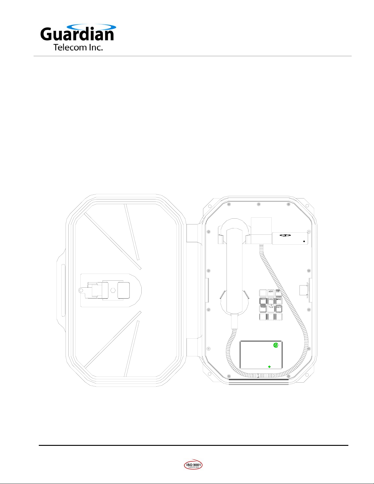
Hazardous Area, Vandal Resistant Telephone
Model VR700
Installation and Operation
GUARDIAN TELECOM
Tel.: (403) 258-3100
VANDAL RESISTANT TELEPHONE
Fax: (403) 253-4967
Class I, DIV. 2, Groups A, B, C, and D
Class I, Zone 2, Group IIC Hazardous Locations
L.N. 21
LINE VOLTAGE: 24 - 56V DC
LOOP CURRENT: 20 - 120mA.
RINGER SENSITIVITY: 40 - 100V, 16 - 25Hz.
SEE USER'S GUIDE FOR INSTALLATION
SER. NO.: VR7XXXX
DO NOT DISCONNECT POWER W HI LE CIRCUITS ARE LIVE
WARNING:
UNLESS AREA IS KNOWN TO BE NO N-HAZARDOUS. DO NOT
REPLACE FUSE WHILE CIRCUIT IS LIVE OR WHILE AREA IS KNOWN
TO BE HAZARDOUS. FIELD REPAIR IS NOT POSSIBLE.
SEE INSTRUCTION MANUAL FOR PROPER OPERATION AND
INSTALLATION INSTRUCTIONS.
VR700
Temperature code T5
Enclosure Type 4X
MADE IN CANADA
1 2
4 5
*
Guardian
87 9
0
LR65547
R.E.N. 0.8B
Telecom Inc.
www.guardiantelecom.com
3
6
#
PHONE: (403) 258-3100
IN NORTH AMERICA
TOLL FREE: 1-800-363-8010
MADE IN CANADA
P004210 Rev. E 041116 3/7/2007 3:48 PM
7552 - 10th Street N.E. Calgary, Alberta, Canada T2E 8W1
Ph: 403.258.3100 \ email:info@guardiantelecom.com \ www.guardiantelecom.com

Guardian Telecom Inc.
(1)
(2)
(1)
(1)
Installation and Operation
Table of Contents
Package Contents......................................................................................................2
Models and Options ...................................................................................................2
Accessories................................................................................................................2
Overview ....................................................................................................................3
Features.....................................................................................................................3
Installing the VR700...................................................................................................5
Maintenance...............................................................................................................7
Operation ...................................................................................................................7
Fuse Replacement.....................................................................................................7
Engineering Specifications.........................................................................................8
Warranty...................................................................................................................10
Disclaimer ................................................................................................................10
Warning....................................................................................................................10
Service Telephone Number......................................................................................10
Feedback .................................................................................................................10
Guardian Product Return .........................................................................................11
Model VR700
Table of Figures
Figure 1 - Overall Dimensions....................................................................................4
Figure 2 - Installation..................................................................................................4
Figure 3 - Setting Dialing Mode..................................................................................6
Figure 4 - I.D. and Compliance ..................................................................................9
Package Contents
VR700 Telephone
Door Latch Keys
Mounting Plate
Installation & Operation Manual
Models and Options
• P5710 Model VR700 Hazardous Area Telephone
Accessories
• P7226 Hazardous Area Ring Detect Relay
• P7231 Hazardous Area Off-hook Detect Relay (24V)
• P7021 CE20 Hazardous Area External Ringer
Page 2

Guardian Telecom Inc.
Installation and Operation
Model VR700
Overview
Hazardous Area Telephone
The VR700 is a vandal resistant telephone designed to provide safe, reliable communication in Class
I, Division 2, hazardous locations. The unit is housed in a rugged, weather and corrosion resistant
enclosure that ensures the unit will function dependably in the most severe conditions.
Features
Enclosure
• polyurethane body construction
• weatherproof and corrosion resistant
• spring loaded hinged door
• stainless steel faceplate
Keypad
• standard 3x4 matrix
Encapsulated Circuitry
• circuit boards are resistant to corrosive agents (e.g. H
NH
) and environments with high humidity
3
S, SO2, and
2
Magnetic Reed Hook Switch
• no moving parts
Surge Arrestor and Field Replaceable Fuse
• prevents damage to the electronic circuitry in the event of a high
voltage spike on the telephone line
Wall Mount
• easily mounted on any sturdy vertical structure
Noise Reducing Microphone
• allows a high level of intelligibility in locations with high background
noise
Tone (DTMF) Operation
• factory set to tone (DTMF) dialing
• can be ordered set for pulse dialing or configured in the field
Armored Handset Cord
• withstands severe use
Hearing-Aid Compatible
• compatible with inductively coupled hearing-aid devices
Page 3
Guardian Telecom Inc.
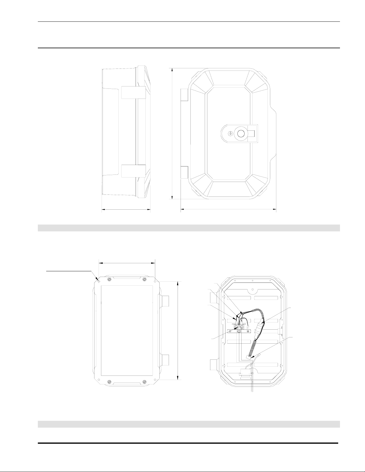
16.4" [417mm]
Installation and Operation
Model VR700
Ø0.265" [Ø7mm]
for #10 or M5
6.3" [160mm]
8.0" [203mm]
12.0" [305mm]
Figure 1 - Overall Dimensions
ORANGE
GREEN
2 WIRE
BLUE
SURGE
ARRESTOR
14.0" [355mm]
FUSE
CONNECT TO
CIRCUIT BOARD
HARNESS
TIP
RING
GROUND FROM EXCHANGE
BACK VIEW
Figure 2 - Installation
Page 4
 Loading...