

Guardian Telecom SR40, SR60 Installation & Operation Manual
P004562 Rev. H 180430 4/30/2018 12:24 PM
Explosion Proof Speaker, Ringer & Speaker/Ringer
Models SR40 and SR60
Installation & Operation
Ph: 403.258.3100 \ email:info@guardiantelecom.com \ www.guardiantelecom.com

Guardian Telecom Installation and Operation
Page 2
Table of Contents
Table of Figures
Package Contents
One (1) SR40 or SR60 Ringer, Speaker or Speaker Ringer
One (1) Installation & Operation Manual
Model SR40/SR60
Overview ......................................................................................................................... 3
Features .......................................................................................................................... 3
Accessories ..................................................................................................................... 3
SR40/60 Models and Options .......................................................................................... 4
Installing the SR40/60 ..................................................................................................... 5
Wiring and Setting up the SR40/60.................................................................................. 6
P7240 24V, P7243 230V, P7248 12V and P7250 120V Ringers .............................. 6
P7241 24V, P7244 230V, P7249 12V and 7251 120V Ringers with 70V Paging ...... 7
P7245 SR40 and P7260 SR60 70V Paging Speakers .............................................. 8
P7246 SR40 70V Paging Speaker with DC Filter Circuit .......................................... 9
P7247 SR40 and P7262 SR60 16 Ohm Paging Speakers ...................................... 10
Maintenance .................................................................................................................. 10
SR40/60 Replacement Parts ......................................................................................... 10
SR40 Specifications ...................................................................................................... 11
SR60 Specifications ...................................................................................................... 13
Storage ......................................................................................................................... 14
Cleaning Tips for Guardian Telephones ........................................................................ 14
APPENDIX A - Hazardous Location Classification ........................................................ 15
Warranty ....................................................................................................................... 17
Disclaimer ..................................................................................................................... 17
Warning ......................................................................................................................... 17
Service Telephone Number ........................................................................................... 17
Feedback ...................................................................................................................... 17
Guardian Product Return ............................................................................................... 18
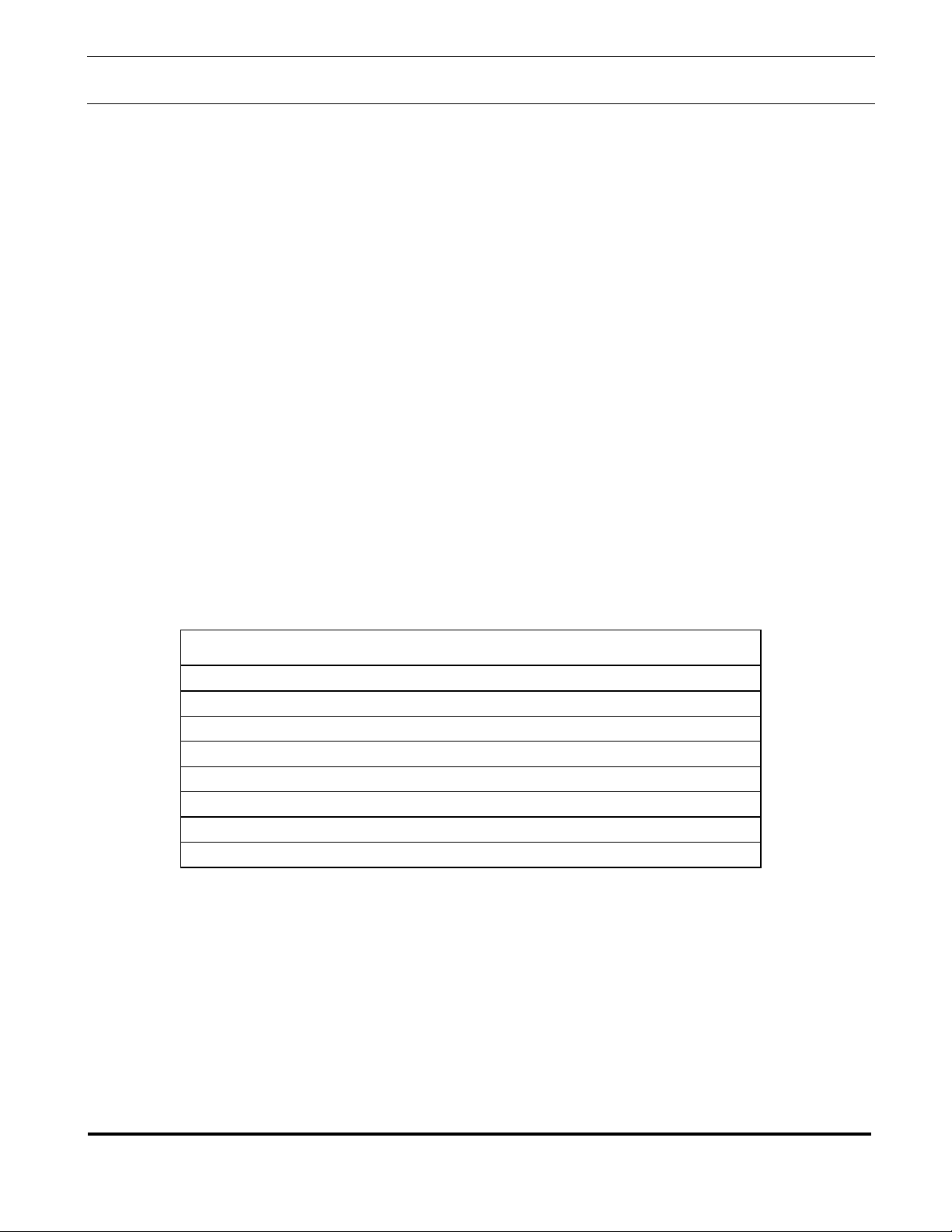
Figure 1 - Overall Dimensions.............................................................. 4
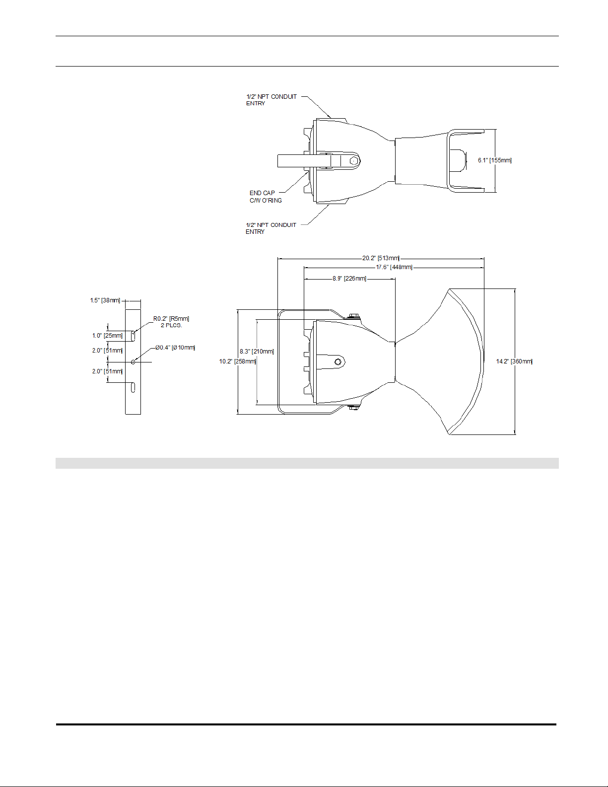
Figure 2 - Ringer Wiring ....................................................................... 6
Figure 3 - Ringers with 70V Paging ..................................................... 7
Figure 4 - Paging Speakers Wiring ...................................................... 8
Figure 5 - Paging Speaker with DC Filter Circuit .................................. 9
Guardian Telecom Installation and Operation
Page 3
SR40/SR60 Explosion Proof Speaker/Ringer
Guardian Telecom’s rugged, versatile SR40 and SR60 Hazardous Area Speaker/Ringers can be set
only and model P7246 is a 70V speaker with DC filter circuit to monitor line integrity.
Body and Cap Construction
Cast, copper free aluminum
• Powder coated
Compliance
Hazardous areas
Weatherproof
Sound Pressure Level (SPL)
110 dB at one meter
P7226 Hazardous area ring detect relay
P7231 Hazardous area off-hook detect relay
Model SR40/SR60
Overview
up as loud speakers for paging applications, loud ringers to signal incoming phone calls, or both
functions can be combined in one device. Approval for use in hazardous areas makes these
speaker/ringers ideal for use in harsh, industrial environments. SR40’s and SR60’s generate up to
110dB and can be factory set in ringer configuration for 12, 24, 120 or 230 volts AC. The SR40 has
a 40 watt driver and the SR60 has a 60 watt driver.
SR40/60 speakers are designed to provide security against ignition of the surrounding atmosphere.
All parts of the apparatus, which might produce an electrical spark, are completely enclosed. All
passages to the outside are made such that any spark or flame will be cooled to a temperature below
the ignition threshold before reaching the outside atmosphere.
The SR40/60 Models P7240 and P7243 are loud Telephone Ringers while models P7241 and P7244
are ringers with additional 70V paging capability. In order for these products to operate as a
telephone ringer, a ring detect relay is needed to control the AC voltage to the ringer circuit when the
telephone ringing signal is detected. All ringers are capable of producing a sound pressure level of
110 dB, which is adjustable on the circuit board. The Paging function of the speaker is designed to
operate on a 70 Volt audio system and comes factory set to 30 Watts, (15 Watts when combined with
the ringer function). A jumper setting on the circuit board is used to select lower wattage levels.
Models P7247 and P7262 are 16 ohm speakers only, models P7245 and P7260 are 70V speakers
Features
•
•
•
•
Accessories
•
•
Guardian Telecom Installation and Operation
Page 4
SR40/60 Models and Options
P7240 SR40, 24V Ringer
P7241 SR40, 24V 15 Watt Paging Loudspeaker/Ringer
P7243 SR40, 230V Ringer
P7244 SR40, 230 V, 15 Watt Paging Loudspeaker/Ringer
P7245 SR40, 30 Watt 70V Paging Loudspeaker
P7246 SR40, 30 Watt, 70V Paging Loudspeaker with DC Filter Circuit for Monitoring Line Integrity
P7247 SR40, 30 Watt, 16 Ohm Paging Loudspeaker
P7248 SR40, 12V Ringer
P7249 SR40, 12V, 15 Watt Paging Loudspeaker/Ringer
P7250 SR40, 120V Ringer
P7251 SR40, 120V, 15 Watt Paging Loudspeaker/Ringer
P7260 SR60, 60 Watt, 70V Paging Loudspeaker
P7262 SR60, 60 Watt, 16 Ohm Paging Loudspeaker
Model SR40/SR60
•
•
•
•
•
•
•
•
•
•
•
•
•
Figure 1 - Overall Dimensions

Guardian Telecom Installation and Operation
Page 5
Installing the SR40/60
the device or result in non-performance.
• Declassify the hazardous location or disconnect wiring in a safe area
before proceeding with any installation or electrical wiring.
• Ensure that none of the electrical connection circuits are live.
• Install the SR40/60 according to appropriate electrical codes using
approved electrical fittings.
Note: This device must be wired using Division 2 wiring methods as
installation in the United States.
• Choose a wall location that is free of obstructions and permits space for ½”
NPT conduit runs or other approved wiring methods.
• Consider the need to later access the interior of the speaker when selecting
the mounting method.
• Ensure mounting can support 20lbs. (9kg).
Use a small diameter rod to remove the end cap.
Make any required checks and adjustments before mounting the speaker.
• Mount with two 3/8” bolts or equivalent
• Replace the end cap and tighten firmly ensuring that the faces of the end
cap and the body are in contact.
• Apply power to the system.
Model SR40/SR60
• Ensure that the device is suitable for the intended service e.g. telephone
ringer, ringer/paging, paging only. Also check to ensure that the device will
handle the voltages and signals that will be supplied. Switching from 120 to
230 VAC and from 12 to 24 VAC can be accomplished in the field by
changing jumpers on the circuit board. It is not possible to switch between
high and low voltage ranges in the field, the proper voltage range must be
ordered from the factory. Application of incorrect voltage may damage
specified in 501-4(b) of the National Electrical Code NEPA 70, for
•
•
See: SR40/60 Models
and Options
Caution: Installation or
electrical wiring in a
hazardous location
could result in serious
injury to personnel or
damage to property.
See: Figure 1 - Overall
Dimensions.
See: Wiring and Setting
up the SR40/60
• Run wiring into the body of the device.
• Make wiring connections as instructed on the following pages.
• Ensure that threads and sealing surfaces are clean and undamaged.
• Test the unit by making a call to the telephone to which the ringer is
connected and/or making a paging call.
Guardian Telecom Installation and Operation
Page 6
Wiring and Setting up the SR40/60
such as Guardian’s P7226 Ring Detect Relay.
• Confirm that the AC voltage supply matches the voltage requirements for
the SR40 ringer board (12/24 VAC or 120/230 VAC).
• Confirm that the jumpers on the circuit board are set to the correct voltage
as per the part number.
• Ensure that none of the electrical connection circuits are live.
• Attach the AC wires to the designated points on the circuit board terminals.
Model SR40/SR60
P7240 24V, P7243 230V, P7248 12V and P7250 120V Ringers
• Note: The SR40 ringer requires an externally switched power supply
• Reduce the ringer volume if desired by adjusting the control on the circuit
board.
See: SR40/60 Models
and Options
See: Figure 2 - Ringer
Wiring
Figure 2 - Ringer Wiring
 Loading...