

Page 1
Industrial Communications Worldwide
A
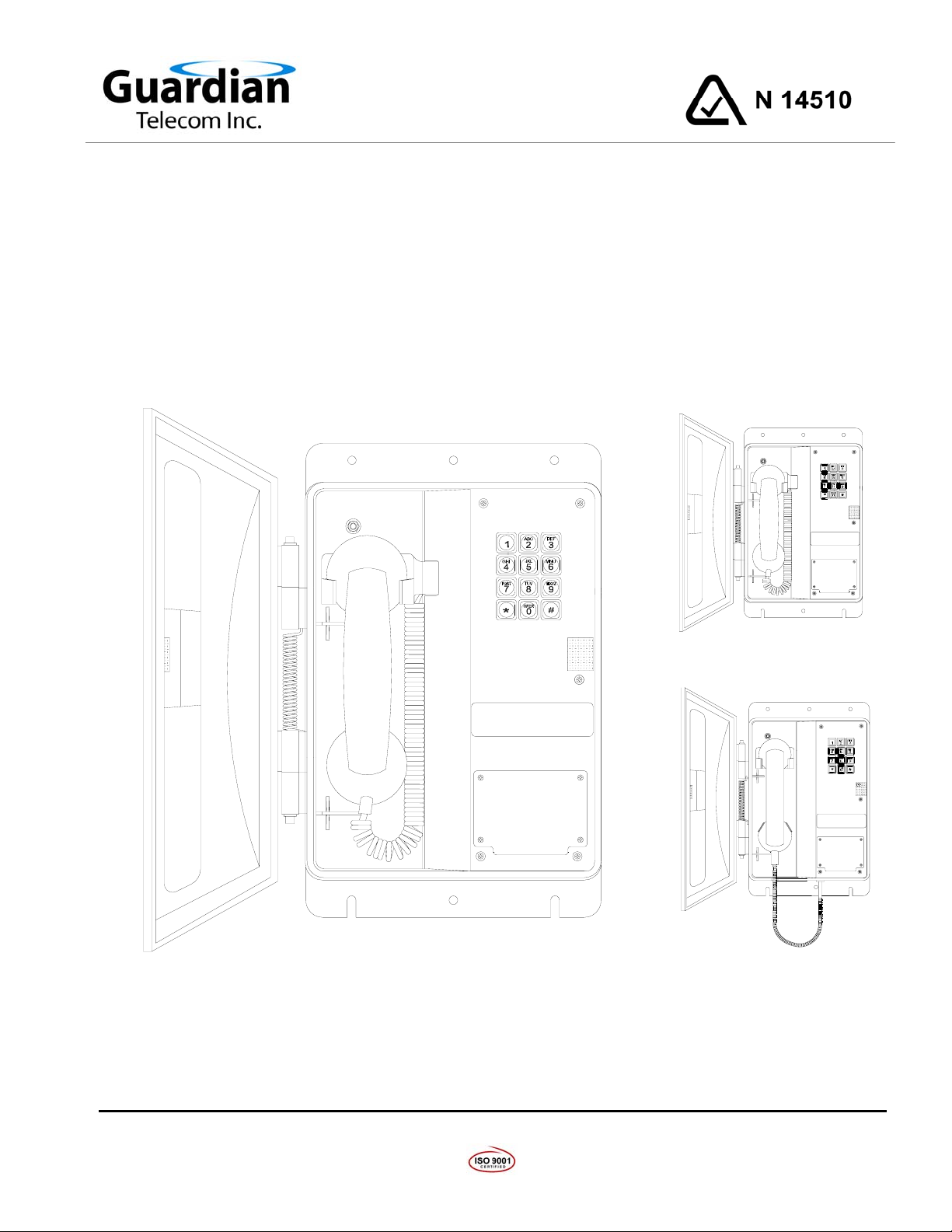
Weather Resistant Industrial Telephones
WRT-A Series
Installation & Operation
WRT-10-A
WRT-10-A
WRT - 30 - A
WRT-30-
WRT-40-A
P006290 Rev. A 5/19/2005 8:09 AM
Ph: 403.258.3100 \ email:info@guardiantelecom.com \ www.guardiantelecom.com
7552 - 10th Street N.E. Calgary, Alberta, Canada T2E 8W1
Page 2

Guardian Telecom Inc.
Installation and Operation
Model WRT-A
Table of Contents
Package Contents.................................................................................2
WRT-A Models and Options .................................................................2
Options Available..................................................................................2
Overview...............................................................................................3
Standard Features On All Models.........................................................3
Installing the WRT-A.............................................................................5
Operation ..............................................................................................5
Setting Dialing Mode.............................................................................6
Field Repairs & Adjustments.................................................................7
Engineering Specifications....................................................................8
Replacement Parts................................................................................9
Government Certification ....................................................................10
Warranty..............................................................................................11
Disclaimer ...........................................................................................11
Warning...............................................................................................11
Service Telephone Number ................................................................11
Feedback ............................................................................................11
Guardian Product Return....................................................................12
Table of Figures
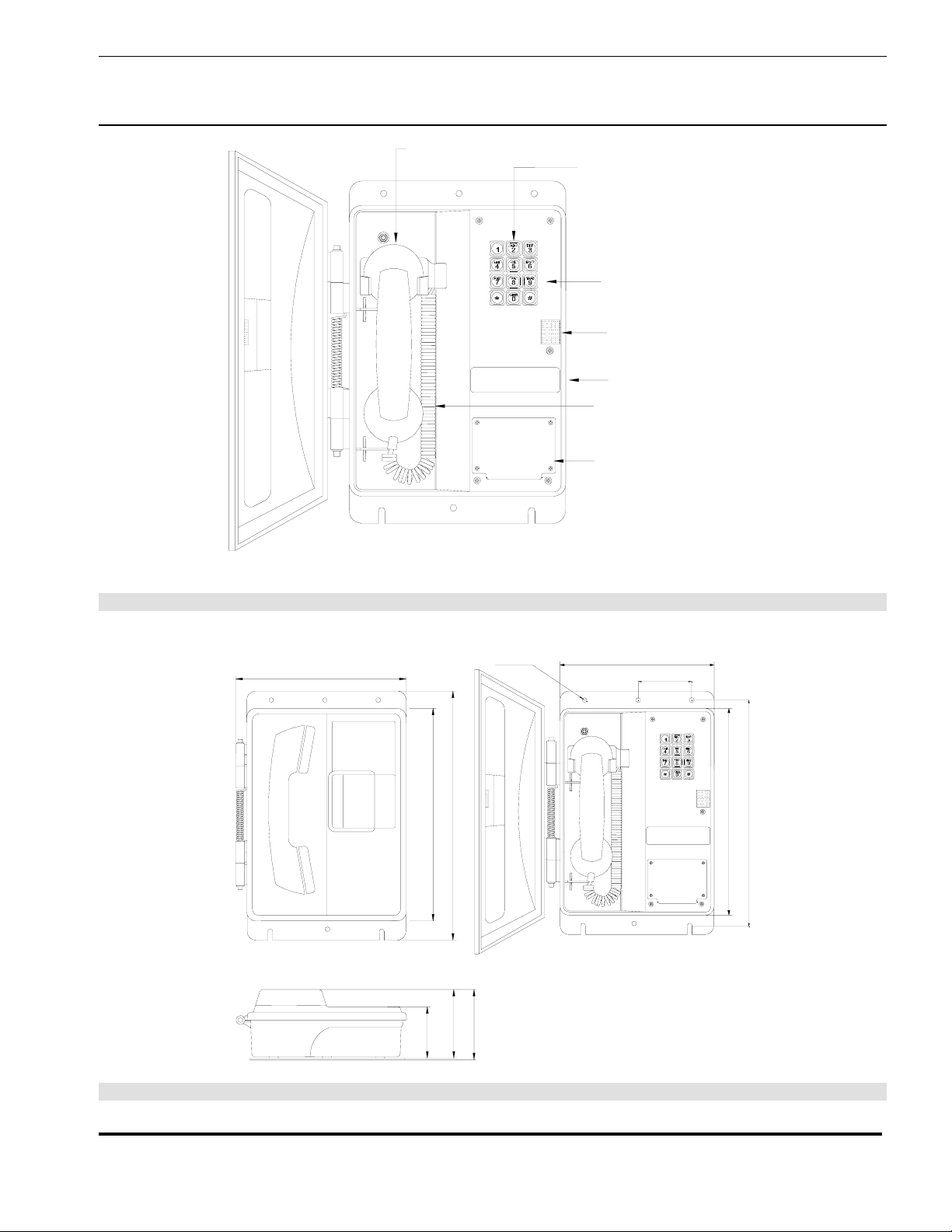
Figure 1 - Features - Typical - Standard Models...................................4
Figure 2 - Overall Dimensions...............................................................4
Figure 3 - Setting Dialing Mode & Installation.......................................6
Figure 4 - Fuse Replacement................................................................7
Package Contents
(1) WRT-A Telephone
(1) Installation & Operation Manual
WRT-A Models and Options
Part No. Model Description
P6050 WRT-10-A Weather Resistant Telephone with Teleseal Keypad & 6’ Heavy Duty
Curly Cord
P6052 WRT-30-A Weather Resistant Telephone with Metal Keypad & Heavy Duty Curly
Cord
P6053 WRT-40-A Weather Resistant Telephone with Metal Keypad, Armored Handset
Cord & Handset Retainer Clip
Options Available
20’ Heavy Duty Curly Cord (20C) (Not available with WRT-40-A)
Noise Canceling Microphone (NC)
Grey Enclosure (GR)
Page 2
Page 3

Guardian Telecom Inc.
Installation and Operation
Model WRT-A
Overview
WRT-A Weather Resistant Telephone Series
WRT-A telephones are designed to provide safe, reliable communication in areas prone to high
humidity, chemical vapors, dust and physical abuse. Several variations and options are available to
suit the end user’s requirements.
Standard Features On All Models
Enclosure
• Weather tight, rugged Valox
• Spring loaded hinged door
Faceplate
• 16 Gauge steel – satin coat primed and powder coated, with wiring
access to surge arrestor
Mounting Plate
• Stainless steel back plate for ease of mounting
Encapsulated Circuitry
• Circuit boards are resistant to corrosive agents (e.g. H
NH
), and environments with high humidity
3
Surge Arrestor
• Protects the user in the event of a high voltage spike on the telephone
line
Fuse
• Prevents damage to the electronic circuits in the event of a high
voltage spike on the telephone line
Magnetic Reed Hook Switch
• No moving parts
Tone (DTMF) Operation
• Factory set to tone (DTMF) dialing
• Pulse dialing can be ordered or configured in the field
6’ Heavy Duty Handset Cord (Not Available With WRT-A-40)
• Withstands severe use
Hearing-Aid Compatible (HAC) Receiver
• Compatible with inductively coupled hearing-aid devices
®
& steel
S, SO2, and
2
Page 3
Page 4
Guardian Telecom Inc.
Installation and Operation
Model WRT-A
MAGNETIC REED HOOK SWITCH
3X4 KEYPAD
(WRT-10-WATERPROOF, WRT-30 &
WRT-40 - METAL)
16 GA STEEL, SATIN COAT
PRIMED AND POWDER COATED
VELCRO DOOR LATCH
ID & APPROVALS
HEAVY DUTY HANDSET
CORD
WIRING ACCESS PLATE
Figure 1 - Features - Typical - Standard Models
9.7" [246mm]
Ø0.3" [Ø7mm]
]
]
m
m
m
m
5
6
0
5
3
3
[
[
"
"
0
0
.
.
2
4
1
1
]
]
m
]
m
m
4
7
[
"
9
.
2
m
m
m
7
9
9
9
[
[
"
"
8
9
.
.
3
3
8.8" [224mm]
3.0" [75mm]
]
]
m
m
m
m
0
0
0
3
3
3
[
[
"
"
8
0
.
.
1
3
1
1
Figure 2 - Overall Dimensions
Page 4
Page 5
Guardian Telecom Inc.
Installation and Operation
Model WRT-A
Installing the WRT-A
• WRT-A telephones shall be installed by qualified service personnel.
• The WRT-A is set to tone dialing when shipped. If pulse dialing is required
see the section on Setting Dialing Mode.
• Follow all appropriate electrical codes and use only approved electrical
fittings for the installation.
• Choose a wall location that is free of obstructions and permits space for
wiring.
• Ensure mounting can support 6.5 lbs (2.95 kg) plus any additional,
foreseeable load.
• Ensure that none of the electrical connection circuits are live.
Mounting
• Use the template or the unit itself to locate and drill holes for mounting
screws.
• Secure the unit to the wall.
Hard Wiring the WRT-A to the Telephone System
• Remove the wiring access cover plate.
• Install a suitable conduit hub or cable gland in the cable entrance hole.
• Bring cable into the enclosure through the cable entrance and attach
individual wires from the exchange – Tip/Ring/Ground – to the surge
arrestor (Tip & Ring are not polarity sensitive).
WARNING
Protective earthing terminal of the phone shall be properly hardwired
• Replace the wiring access cover plate.
Final Check
• Check the set visually for loose screws and trapped wires. Check that the
handset hangs freely in the cradle and that the handset cord is not trapped
by the door.
• Check that the faceplate is snug to its gasket, paying particular attention to
the area around the cradle. Check that the door closes flush to the housing.
• Test the unit by calling to and from another unit on the exchange.
to a protective earth system.
See: Figure 3 - Setting
Dialing Mode &
Installation
See: Figure 2 - Overall
Dimensions
Operation
• Once your Model WRT-A Telephone has been properly installed and
energized, operation is identical to most other single line telephones.
WARNING
Due to magnetic fields, it is possible that dangerous objects may get trapped
within the earcap region of this device.
Page 5
Page 6

Guardian Telecom Inc.
Installation and Operation
Model WRT-A
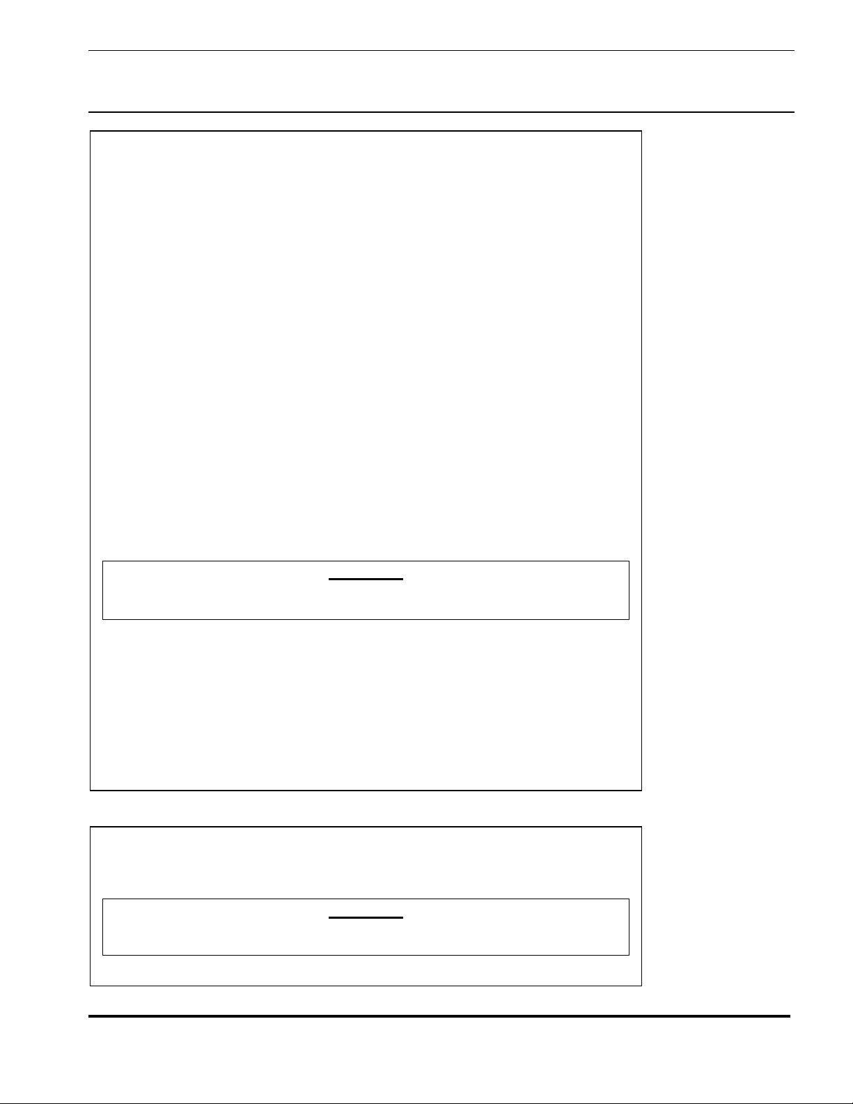
Setting Dialing Mode
The WRT-A is shipped from the factory set for DTMF (Tone) dialing mode. If
loop disconnect (Pulse) dialing is required proceed as follows.
• Loosen the five captive screws in the faceplate and swing the faceplate to
the left. If the set is on a vertical surface the faceplate will stay open like a
book in this position. Take care not to disturb the internal wiring.
• Change the position of the Tone/Pulse jumper on the circuit board to Pulse,
as indicated on the label.
• The set will now be in pulse dialing mode, it can be returned to tone mode
by changing the position of the jumper back to the Tone position.
• Carefully replace the front plate and install all five screws. Do not over
tighten the cover screws, there is a flexible gasket between the cover and
the body. Excessive tightening of the screws deforms the gasket and
reduces the weather resistance of the set.
See: Figure 3 - Setting
Dialing Mode &
Installation
TONE/PULSE
F
Guardian Telecom Inc.
S/N:____________
Calgary, Canada
RIN-
PHONE
TONE/
HANDSET
GERHKSW
LINE
PULSE
JUMPER
GROUND CONNECTION
TIP & RING CONNECTION
Figure 3 - Setting Dialing Mode & Installation
Page 6
Page 7

Guardian Telecom Inc.
Installation and Operation
Model WRT-A
Field Repairs & Adjustments
Field repairs may only be carried out by qualified technicians using OEM parts.
Substitution of parts voids warranty and may pose a hazard to users of the
equipment.
See: Replacement Parts
• Disconnect the telephone from Tip and Ring power supplied by the PABX
or central office before attempting repairs.
• Loosen the five captive screws in the faceplate and swing the faceplate to
the left. If the set is on a vertical surface the faceplate will stay open like a
book in this position. Take care not to disturb the internal wiring.
• Perform the necessary repairs or adjustments.
• Carefully replace the front plate and install all five screws. Do not over
tighten the cover screws, there is a flexible gasket between the cover and
the body. Excessive tightening of the screws deforms the gasket and
reduces the weather resistance of the set.
Fuse Replacement
• Remove the old fuse by pushing in the end cap of the fuse holder and
turning counterclockwise to open. Insert a new 0.25 amp, 250Volt, 3AG
fast blow fuse and close the fuse holder.
WARNING!
• Replace only with a 0.25 amp 250V 3AG fast blow fuse. Failure to do so
will void the warranty.
• If, on reconnecting power, the fuse fails, check the telephone system
wiring. The fuse protects the Tip and Ring line from the telephone system.
It is usually powered at 48 volts DC and must not be connected to 120 volts
AC.
See: Figure 4 - Fuse
Replacement
Note: Ensure that
connections are secure
before replacing
faceplate.
FUSE
0.25 AMP .3AG
FAST BLOW
GROUND CONNECTION
GROUND
TIP & RING CONNECTION
Figure 4 - Fuse Replacement
Page 7
Page 8

Guardian Telecom Inc.
Installation and Operation
Model WRT-A
Engineering Specifications
*ELECTRICAL PERFORMANCE
AUDIBLE RANGE FREQUENCY RESPONSE 300 – 3400 HZ
DIALING METHOD DTMF OR 33/66 PULSE AT 10 PPS
SEND LOUDNESS RATING (SLR) dB SHORT 8 dB +/- 4 dB
RECEIVE LOUDNESS RATING (RLR) dB SHORT -4 dB +/- 4 dB
SIDE TONE MASKING RATING (STMR) >11 dB
RINGER OUTPUT 75 dB MAXIMUM
RINGER EQUIVALENCE 0.5
SET IMPEDANCE 600 OHMS NOMINAL
MAXIMUM LOOP 15,000 FT (4,600 M) OF 22 AWG COPPER
ELECTRICAL
RINGER SENSITIVITY 40 – 100 V, 16 – 25 HZ
LINE VOLTAGE 24 – 56 VDC
LOOP CURRENT 20 - 120 mA
URGE ARRESTOR / TERMINAL BLOCK
CONNECTION METHOD
S
FUSE ¼ AMP 250 VOLT 3AG FAST BLOW
ENVIRONMENTAL
WEATHERPROOF ENCLOSURE NEMA 3R
TEMPERATURE -40
O
TO +60
O
C (-40
O
TO +140
O
F)
HUMIDITY 0 TO 95% RH
DUSTPROOF FULLY GASKETED FACEPLATE & WEATHERPROOF KEYPAD
CORROSION RESISTANT MIL-STD-810E SALT FOG
MECHANICAL
HOOK SWITCH (CRADLE SWITCH) LIFE >1 000 000 OPERATIONS
BODY CONSTRUCTION
GE V
ALOX 357
®
ENGINEERING POLYMER
DIMENSIONS 12 X 9.6 X 3.9 INCHES (305 X 245 X 99 MM)
NET WEIGHT 6.5 LBS (2.95 KG)
HANDSET MATERIAL HIGH IMPACT ABS
MICROPHONE NOISE REDUCING ELECTRET
OPTIONAL MICROPHONE NOISE CANCELING DYNAMIC
RECEIVER HEARING AID COMPATIBLE (HAC)
STANDARD MOUNTING VERTICAL WALL
WIRING ACCESS 7/8” DIAM. OPENING FOR OWNER SUPPLIED FITTING
Page 8
Page 9

Guardian Telecom Inc.
Installation and Operation
Model WRT-A
OMPLIANCE
C
ACA N14510
DOC 1012 6721 A
FCC HQHCAN-22517-TE-E
WEATHERPROOF ENCLOSURE NEMA 3R
ENVIRONMENTAL SURVIVABILITY MIL-STD-810E
Replacement Parts
Part No. Description
P005765 Faceplate WRT-A (All Models)
P003022 Handset Shell C/W 22” Armored Cord
P002294 Handset Shell Only – For WRT-10-A & WRT-30-A
P002554 Cord – Handset 6’
P005961 Handset Cradle C/W Reed Switch
P004371 Handset Retainer – WRT-40-A Only
P000028 Microphone Cartridge – Noise Reducing
P004538 Microphone Cartridge – Noise Canceling
P002080 Receiver Cartridge
P006307 Handset Assembly Complete – C/W 6’ Curly C ord For WRT-10-A & WRT-30-A
P004259 Handset Assembly Complete – C/W 22” Armo red C ord For WRT-40-A
P006291 Keypad Assembly – Plastic C/W Telephone Circuit Board For WRT-10-A
P006281 Telephone Circuit Board
P005576 Keypad – Plastic For WRT-10-A
P000907 Keypad Cover – Teleseal For WRT-10-A
P006295 Keypad – Metal For WRT-30-A & WRT-40-A
P002782 Ringer – Floyd Bell BR-3-39
P005917 Reed Switch
P002992 Surge Arrestor – TII 126L1
P002991 Fuse – Glass 0.25 Amp 250V
P000126 Housing
P003045
P002988
P001706
P001488
P002995
Backplate
Door C/W Velcro Latch
Hinge Pin – 8.390 Nylon
Door Spring
Hinge Pin Retaining Ring
Page 9
Page 10

Guardian Telecom Inc.
Installation and Operation
Model WRT-A
Government Certification
Attached to the telephone is a label for the Australian Communications Authority. This identifies
equipment certifications indicating the WRT-A series telephones meet certain telecommunications
network protective, operational and safety requirements. This agency does not guarantee the
equipment will operate to the user's satisfaction.
Before installing this telephone equipment, users should ensure it is permissible to connect the
equipment to facilities of the local telecommunications company.
Equipment must be installed using acceptable connection methods. In some cases, the telephone
users inside wiring, associated with a single line service, may be extended by a certified connector
assembly (telephone extension cord). The customer should be aware that in some situations
compliance with the above conditions may not prevent degradation of service.
Repairs to certified equipment should be made by a supplier designated authorized maintenance
facility.
For their own protection users should ensure the electrical ground connections of the power utility,
telephone lines and internal metallic water pipe systems, if present, are connected. This precaution
may be particularly important in rural areas.
CAUTION: Users should not attempt to make ground connections, but should contact the appropriate
electrical inspection authority or electrician.
Notification to Telephone Company
Upon request, the customer must notify the telephone company of the particular line to which the
connection will be made and provide the Australian Communications Authority registration number. The
local telephone company may request disconnection of the telephone where alterations or malfunctions
affect the telephone’s performance.
ACA Rules and Ringer Equivalence Number
This equipment complies with the regulation AS/ACIF S002:2001 Australian Standard Analogue
internetworking and non-interference requirements for customer equipment for connection to public
switched telephone networks. On the side of this equipment is a label that contains, among other
information, the ACA registration number and ringer equivalence number (REN) for this equipment. If
requested, this information must be provided to the telephone company.
The REN is used to determine the quantity of devices which may be connected to the telephone line.
Excessive RENs on the telephone line may result in the devices not ringing in response to an incoming
call. In most, but not all areas, the sum of the RENs should not exceed three. To be certain of the
number of devices that may be connected to the line, as determined by the total RENs, contact the
telephone company to determine the maximum REN for the calling area.
Service changes and Limitations
The telephone company may make changes in its facilities, equipment, operations, or procedures that
could affect the operation of the equipment. If this happens, the telephone company will provide
advance notice in order for you to make the necessary modifications in order to maintain uninterrupted
service.
This equipment can not be used on public coin telephone service as provided by your telephone
company. Connection to party line service is subject to state tariffs (contact the state public utility
commission, public service commission or corporate commission for information.)
Page 10
Page 11

Guardian Telecom Inc.
Installation and Operation
Model WRT-A
Warranty
Guardian Telecom warrants your product to be free of defects in material and workmanship for a period
of one year. Guardian Telecom will repair or replace any defective unit that is under warranty free of
charge.
This warranty is null and void if any non-authorized modifications have been made to this product, or if
it has been subjected to misuse, neglect, or accident. This warranty covers bench repairs only; such
repairs must be made at Guardian Telecom or an authorized service depot. Guardian Telecom is not
responsible for costs incurred for on-site service calls, freight, or brokerage.
A return authorization must be obtained prior to warranty claims or repairs.
Disclaimer
The products covered by this manual are designed for use in Industrial Environments and/or Hazardous
Locations. Due to the range of possible applications for these instruments the manufacturer will not be
responsible for damages or losses of any kind suffered as a result of the use of this product, including
consequential damages.
Warning
This device may be opened and reassembled by qualified personnel only, for the purposes of installing
the product, making adjustments and replacing components, following the instructions in the product
manual.
High voltages may be present in this product when connected to telephone wiring.
Service Telephone Number
1-800-363-8010 – North America
Guardian Telecom provides a customer service telephone number which is toll-free within North
America. The Authorized Dealer/Service Depot is listed below for your area. If you need assistance
when installing or operating this product, please call the toll-free telephone number or the Authorized
Service Depot between regular business hours (8:00AM-5:00PM). If you are calling outside regular
business hours, please leave a detailed message, and a member of Guardian Telecom’s Service
Department will return your call as soon as possible. If your product requires service, Guardian
personnel will supply you with an RMA (return materials authorization) number over the telephone or
through our web site product return page at
included with your return address and the name of the person to contact.
http://www.guardiantelecom.com. This number must be
Qmax Group Pty Ltd
21 Jubaea Crt
Canning Vale
Western Australia 6155
Phone (08) 9455-4671
Fax (08) 6210-1749
Email :
info@qmax.net.au
(Click to open message box)
Feedback
Guardian Telecom continually strives to make reliable, durable, and easy to use products. If you, as an
installer or user of our equipment, have any suggestions for improvements to this or any of our products
or documents, including this manual, we would appreciate hearing from you.
Page 11
Page 12

Guardian Telecom Inc.
Installation and Operation
Model WRT-A
Guardian Product Return
Guardian products have been quality tested and are in full working order when shipped from
the factory, given the rugged nature of these products shipping is not expected to damage a
unit. In the unlikely event of a malfunction, Guardian follows the three step procedure below.
Step I - On-Site Correction
• The most common source of difficulties with a new product is improper installation in one of
two ways: incorrect wiring connections or connection to an incorrect power sou r ce.
• Product wiring needs to be properly connected to the on-site wiring . Correct wiring
instructions are shown in the user manual included with the product.
• Connecting a telephone to a standard power source, rather than tip & ring, will blow the
telephone’s internal, user-replaceable fuse. In the event of fuse burn-out, disconnect the
telephone from the power source, replace the fuse, and reconnect following the wiring
diagrams provided with the product.
Step II - Return Materials Authorization (RMA)
• When a product has been installed following user manual instructions, and the unit fails to
operate, the user must contact the Service Number indicated on the previous page, to
obtain authorization to return the product.
• After providing information on the product, the owner and the nature of the problem,
Guardian will issue a RMA number, to be shown on documentation returned with the
product.
• In addition to the RMA number, shipping documents should include name, address and
telephone number of the owner along with contact information for the person responsible
for the repair and/or the user who identified the malfunction.
Step III - Factory Authorized Service
• Once received, each product is carefully inspected and tested. If the product is under
warranty, repairs are completed and the product returned to the owner, generally within
five working days of receipt.
• A product that has been subjected to misuse, neglect or accident or is beyond the warranty
period will be evaluated. The service department will provide the owner’s representative
with a repair cost estimate. Once approved, repairs are completed and the prod uct
returned, generally within five working days.
Page 12
Page 13

Guardian Telecom Inc.
Installation and Operation
Model WRT-A
Notes:
Model No.
Part No.
Serial No.
Date of Purchase
Page 13
Page 14

Page 15

Page 16

Guardian Telecom Inc.
7552 - 10th Street N.E.
Calgary, Alberta, Canada T2E 8W1
Toll-free 1-800-363-8010
Ph. (403) 258-3100
Fax. (403) 253-4967
www.guardiantelecom.com
E-mail:
mailto:sales@guardiantelecom.com
(Click to open message box)
Industrial Communications Worldwide
© Guardian Telecom Inc. 2005
 Loading...