

Page 1

Downloaded from: http://www.guardianalarms.net
Page 2

Page 3

DVST Installation Guide January 1996
DFT-0150
INSTALLATION GUIDE
Dedicated Micros UK Ltd.
11, Oak Street, Swinton, Pendlebury.
Manchester.
M27 4FL.
United Kingdom.
Direct Telephone: 0161 727 3241 Direct Fax: 0161 794 4464
Outside UK. Telephone: Int +(44) 161 727 3241 Fax: Int +(44) 161 794 4464
Dedicated Micros U.S.A. Inc.
11515 Sunset Hills Road, Reston, Virginia 22090, U.S.A.
Telephone: Int +(703) 904 7738 Fax: Int +(703) 904 7743
Dedicated Micros (Australia) PTY.
Unit 1, 30 Leighton Place, Hornsby NSW2077, Australia.
Telephone: Int +(612) 482 1857 Fax: Int +(612) 482 1647
Dedicated Micros (Asia) Ltd.
1 Tannery Road, #05-04/05 Cencon 1, Singapore 1334
Telephone: Int +(65) 741 0138 Fax: Int +(65) 741 0221
Dedicated Micros (Belgium) Ltd.
Interleuvenlaan 64, B-3001 Leuven, Belgium
Telephone: Int +(32) 16 40 12 28 Fax: Int +(32) 16 40 02 43
.
© Dedicated Microcomputers Group Ltd. 1995
All rights reserved. No part of this publication may be
reproduced or distributed in any form or by any means
without the prior written permission of the publisher.
Dedicated Micros Ltd Page i
Page 4

6April1995 DVSTInstallationGuide
Microcom ® is a registered trademark of:
Microcom Systems, Inc.
Gandalf ® is a registered trade mark of:
Gandalf Digital Communications Ltd.
Page ii Dedicated Micros Ltd
Page 5

DVSTInstallationGuide Safety
Safety
ReadInstructions-Allthesafetyandoperatinginstructionsshouldbereadbeforetheunitisoperated.
Retaininstructions-Thesafetyandoperatinginstructionsshouldberetainedforfuturereference.
Heed warnings - All warnings on the unit and in the operating instructions should be adhered to.
Follow instructions - All operating and user instructions should be followed.
Cleaning - Unplug the unit from the outlet before cleaning. Do not use liquid cleaners or aerosol
cleaners. Use a damp cloth for cleaning.
Attachments -Do notuse attachments not recommended bythe productmanufacturer as they may
cause hazards.
Water and Moisture - Do not use this unit near water - for example, near a bath tub, wash bowl,
kitchensink,orlaundrytub, in awetbasement,nearaswimmingpool,inanunprotected
outdoor installation, or any area which is classified as a wet location.
Accessories-Do notplacethisuniton anunstablestand,tripod,bracket, or mount.Theunitmay fall,
causingseriousinjurytoa person and seriousdamagetotheunit.Useonlywithastand,
tripod, bracket or mount recommended by the manufacturer, or sold with the product.
Anymountingoftheunit should followthemanufacturer’sinstructions,andshouldusea
mounting accessory recommended by the manufacturer.
Anappliance andcart combinationshouldbe movedwith care. Quickstops, excessive
force,andunevensurfacesmaycausetheapplianceandcartcombinationtooverturn.
Ventilation-Openingsinthe enclosure areprovidedforventilationandtoensurereliableoperationof
the unit and to protect it from overheating. These openings must not be blocked or
covered.This unitshouldnot beplacedin a built-ininstallationunless properventilation
is provided.
Power Sources - This unit should be operated only from the type of power source indicated on the
manufacturer’s label. If youare notsure ofthe typeof thepower supplyyou planto use
consult your appliance dealer or local power company. For units intended to operate
from battery power, or other sources, refer to operating instructions.
Grounding or Polarization- Thisunitmay beequipped withapolarized alternating-currentline plug
(aplughaving onebladewiderthan the other).Thisplugwill fit intothepoweroutlet only
one way. This isa safetyfeature. Ifyou areunable toinsert theplug fullyinto theoutlet,
try reversingthe plug.If the plug should stillfail tofit, contactyour electrician toreplace
your obsolete outlet. Do not defeat the safety purpose of the polarized plug.
Alternatelythisunit may beequippedwitha3-wire grounding-type plug,aplughavinga
third (grounding) pin. This plug will only fit into a grounding-type power outlet. Thisis a
safetyfeature. Ifyouare unable toinsertthe plugintothe outlet,contactyourelectrician
to replace yourobsolete outlet.Do notdefeat thesafety purposeof the grounding- type
plug.
Power-Cord Protection - Power-supply cords should be routed so that they are not likely to be
walked on or pinched by items placed upon or againstthem, payingparticular attention
to cords at plugs, convenience receptacles, and the point where they exit from the
appliance.
Overloading-Donotoverloadoutletsandextensioncordsasthiscanresultinafireorelectricshock.
Objectand Liquid Entry-Never push objectsofany kind intothisunit through openingsasthey may
touch dangerous voltage points or short-out parts that could result in a fire or electric
shock. Never spill liquid of any kind on the unit.
Dedicated Micros Ltd Page iii
Page 6
Safety DVSTInstallationGuide
Servicing - Do not attempt to service this unit yourself as opening or removing covers may expose
you to dangerous voltage of other hazards. Refer all servicing to qualified service
personnel.
Damage Requiring Service - Unplug the unit from the outlet and refer servicing to qualified service
personnel under the following conditions:
(a)When the power-supply cord or plug is damaged.
(b)If liquid has been spilled, or objects have fallen into the unit.
(c)If the unit has been exposed to rain or water.
(d)If the unit does not operate normally by following the operating instructions. Adjust
only those controls that are covered by the operating instructions as an improper
adjustmentof othercontrolsmay resultin damage andwill often requireextensive work
by a qualified technician to restore the unit to its normal operation.
(e)If the unit has been dropped or the cabinet has been damaged.
(f)When the unit exhibits a distinct change in performance this indicates a need for
service.
Replacement Parts -When replacementpartsare required,be suretheservice technicianhas used
replacement parts specified by the manufacturer. A replacement lithium battery is
available from Dedicated Micros Ltd.
Safety Check - Upon completion of any service or repairs to this unit, ask the service technician to
perform safety checks to determine that the unit is in proper operating condition.
Coax Grounding - If an outside cable system is connected to the unit, be sure the cable system is
grounded.
UNPACKING- Theshippingcartonis thesafestcontainer inwhichtheunit maybetransported. Save
it for possible future use.
WARNING - TO PREVENT FIRE OR SHOCK HAZARD, DO NOT EXPOSE THIS EQUIPMENT TO
RAIN OR MOISTURE.
The lightning flash with arrowhead symbol within an equilateral triangle is intended to
alert theuser of this equipment that there aredangerous voltages withinthe enclosure
which may be of sufficient magnitude to constitute a risk of electric shock.
The exclamation point within an equilateral triangle is intended to alert the user to the
presence of important operating and maintenance (servicing) instructions in the
literature accompanying the appliance.
Page iv Dedicated Micros Ltd
Page 7

DVSTInstallationGuide RegulatoryNotes
Regulatory Notes
FCC AND DOC INFORMATION
(U.S.A. and Canadian Models Only)
WARNING
Thisequipment hasbeen testedand found tocomply withthe limits fora ClassA digital
device, pursuant to part 15 of the FCC rules. These limits are designed to provide
reasonableprotection againstharmfulintereference when theequipmentis operatedin
a commercial enviroment. This equipment generates, uses, and can radiate radio
frequency energy and, if not installed and used in accordance with the instruction
manual, may cause harmful interference to radio communications. Operation of this
equipment ina residentialarea islikely tocause harmful interference in which case the
user will be required to correct the interference at his own expense.
If necessary, the user should consult the dealer or an experienced radio/television
technician forcorrectiveaction. The usermayfindthefollowingbooklet prepared bythe
Federal Communications Commission helpful: “How toidentify and Resolve Radio-TV
Interference Problems”. This booklet is available from the U.S. Government Printing
Office, Washington, DC20402, Stock No. 004-000-00345-4.
This reminder is providedto callthe CATVsystem installer’sattention toArt. 820-40of
the NEC that provides guidelines for propergrounding and, in particular,specifies that
thecable groundshallbeconnected tothegroundingsystem ofthebuilding, as closeto
the point of cable entry as practical.
CE Mark
Thisproductis markedwiththeCEsymbol andindicatescompliancewiththe European
Community EMC directive 89/336/EEC.
This mark indicates that this product meets the following technical standards.
•
EN55022 1987-“Limits andMethodsof MeasurementofRadio Interference
Characteristics of information Technology Equipment”.
•
BSEN50082-1 -“Electromagnetic compatibility -Generic immunitystandard
Part 1: Residential, commercial, and light industry”.
•
IEC 801-2 1984, IEC 801-2 1991 - “Electromagnetic compatibility for
industrial process measurement and control equipment Part 2: Electrostatic
discharge requirements”.
•
IEC 801-3 1984 - “Electromagnetic compatibility for industrial-process
measurement and control equipment Part3: Radiated electromagnetic field
requirements”.
Dedicated Micros Ltd Page v
Page 8

RegulatoryNotes DVSTInstallationGuide
IEC 801-4 1988 - “Electromagnetic compatibility for industrial-process
•
measurement and control equipment Part 4: Electrical fast transient/burst
requirements”.
A “ Declarationof Conformity” inaccordance with theabove standardshas beenmade
and is recorded at: Dedicated Micros Ltd., Pendlebury, Manchester, England.
Page vi Dedicated Micros Ltd
Page 9

DVSTInstallationGuide TableofContents
Table of Contents
1 Introduction 1
1.1 DFT-0150 Transmitter 1
1.2 Telemetry 1
1.3 Event monitoring (Alarm) option 1
1.4 Audio option 1
2 Unpacking the unit 3
2.1 Items in packing 3
2.2 Packing the DVST 3
3 Operation 5
3.1 Callback 5
3.2 Alarms feature 5
3.3 Freeze all alarms 6
3.4 No frozen images 6
3.5 Offline frozen alarm 6
3.6 Track last alarm 6
4 Installation 7
4.1 Rear Panel connections 7
Fig: 1 Rear panel layout
Key to Fig: 1
4.2 Power inputs 8
4.3 37 way alarm connecton 8
Fig: 2 Alarm input/output connections
5 Setup 9
5.1 What you require 9
5.2 Setup using a PC 9
5.3 Remote setup 10
5.4 DVST commands 10
HELP
QUIT
RESET
VIEW
5.5 Define camera inputs 11
MAX=nn
COL=nn
MON=nn
CAMnn=5.6 Auxiliary port 3 11
AUX=
5.7 Define auxiliary ports 1,2,3 12
PORT=
Dedicated Micros Ltd Pagevii
Page 10

TableofContents DVSTInstallationGuide
6 Demonstration Mode 13
6.1 Demonstration mode 13
DEMO=
EXTCLK=
6.2 Demo cable 14
Fig: 3 Wiring details for demo cable
6.3 Connecting the demo cable 15
Single cable operation
Fig: 4 Demo Cable Connections
7 Modems 17
7.1 PSTN connection (modem) 17
7.2 MODEM commands 17
MODEM=
MODEM
MBAUD=
MODEM2
PORT=
7.3 Modem configuration strings 19
MODSTR=
MOD2STR=
USER=...
SEND
DIAL=
7.4 Modem operation 21
7.5 Connecting a modem in direct mode 22
Call request
Call answer request
Call disconnect.
Configuration of modem in direct mode
7.6 Using a modem in ATMODE 23
Call request
Call answer request
Call disconnect
7.7 General settings for modems in ATMODE 23
All modems:
Synchronous modems:
Asynchronous modems:
7.8 MOTOROLA VFAST 25
Country specific settings
No dialtone
Transmission speed
7.9 Microcom V3242 27
Syncronous mode :
DIP switch settings synchronous operation
DIP switch settings asyncronous operation
7.10 Trailblazer 28
Async mode
7.11 OCTOCOM OSI 8196A 29
Page viii Dedicated Micros Ltd
Page 11

DVSTInstallationGuide TableofContents
8 Terminal Adapters 31
8.1 ISDN connection (Terminal Adapter) 31
DUALISDN=
ISDN=
8.2 Connecting a terminal adapter in direct mode 32
Making a Call
Answering a Call
Call disconnection
Configuring a terminal adapter for direct mode operation
8.3 Gandalf TA1 33
Direct mode
8.4 ASCOM 5000 / CITAM 34
ATMODE
Fig 5: ASCOM internal dip switch settings (ATMODE)
X21
Fig 6: ASCOM internal dip switch settings (X21)
8.5 Dataflex TA 38
9 Leased Line Transmission 39
9.1 Leased line terminology 39
9.2 DVST set up for leased line operation 39
9.3 Lleased line operation 40
9.2 ASCOM 64000 baseband modem 41
10Calls 43
10.1 Passwords 43
PASSWORD=
PASSn=
SPASSWORD=
10.2 On screen titling 44
SYSTEM=
TIME=
DATE=
TLPOS=
TDPOS=
10.3 Telephone number entries / connection commands 45
TELn=
TELn
TYPEn=
TIMER=
DIALCLR=
10.4 Callback 46
CALLBACK=
11Images and Transmission 47
Screen display - periscope mode
11.1 Image size 47
Target image size =
Dedicated Micros Ltd Pageix
Page 12

TableofContents DVSTInstallationGuide
12Alarms & Events 49
12.1 Purpose & intended use 49
12.2 Alarm connections 49
12.3 ALARM settings 49
ASYS=
AON=n
AOFF=n
ANOnn
ANCnn
Images transmitted on alarm
ATYPEn=
AOUT=
ALMODE=
ADIAL=n
13Audio 53
13.1 Equipment required but not supplied 53
Fig: 7 End Panel Layouts
13.2 Connectint the DAL100 54
Microphone
Speaker
Power supply
DVST connections
Set port usage
Fig: 8 Microphone Connection
14Cable Assemblies 55
14.1 X21 to V35 cable assembly 56
14.2 X21 cable assembly 57
14.4 V24 SYNC cable assembly 58
14.5 RS232 cable assembly (DVST-PC) 59
14.6 RS232 cable assembly (DVST-DAL) 60
15Glossary 61
16Returns Procedure 63
Pagex Dedicated Micros Ltd
Page 13

DVSTInstallationGuide Introduction
1 Introduction
DVSTis thegeneric namefor a rangeof productsdesigned to storeand transmitdigital
pictures at a higher quality and speed than previously possible.
1.1 DFT-0150 Transmitter
The DFT-0150 (Digital Fast Transmission) transmitter will process the imagesfrom up
to sixteen cameras for transmission or reception over ISDN or PSTN telephone lines.
1.2 Telemetry
The DFT 0150 can control telemetry cameras at the local site using built in telemetry
equipment.
1.3 Event monitoring (Alarms)
Theinternalalarmverification system forDFT0150transmitterallowstheunittomonitor
and act onexternal events.This canfreeze a picturefrom thecamera thatcorresponds
to a specific alarm input. The unit will then transmit this picture to the receiving station
where the operator can acknowledge the event and take relevant action.
This versatile alarm interface is a light duty 16 input / 2 output unit.
1.4 Audio option
Audio transmission is available allowing two way, half duplex, (one way at a time)
communication. (Transmission medium must be 19200baud or faster)
Dedicated Micros Ltd Page 1
Page 14

Introduction DVSTInstallationGuide
This page is intentionally blank
Page 2 Dedicated Micros Ltd
Page 15

DVSTInstallationGuide Unpackingtheunit
2 Unpacking the unit
2.1 Items in packing
Theunitshouldbecarefullyunpackedandthepackingmaterialsretained.Checkthatall
the contents on the following checklist are present:
q
q
q
q
DVST Unit
Power Lead with molded IEC connector
Rack mount conversion kit
Installation Guide
2.2 Packing the DVST
If the DVST is to be returned for repair or transported to another location the original
packing should be used.
The unit should first be wrapped in the polythene bag. The preformed end pieces are
thenplaced ateithersideof theunitwhich can thenbeplaced insidethecardboardbox.
The box should be firmly sealed using appropriate tape.
If the unit is to be returned for repair ensure a valid returns note is clearly written
on the side of the box.
Dedicated Micros Ltd Page 3
Page 16

Unpackingtheunit DVSTInstallationGuide
This page is intentionally blank
Page 4 Dedicated Micros Ltd
Page 17

DVSTInstallationGuide Operation
3 Operation
3.1 Callback
The callback feature allows an operator at a monitoring station to call a DFT0100
transmitter onsite and configure the unit to automaticallycall them back,ensuring that
the telephone call is charged to the transmitting and not the receiving site.
On sending a callback request, the monitoring station disconnects and waits for the
transmitting site to call back. With callback enabled, connection time is approximately
twice that of normal connection time.
3.2 Alarms Feature
Thealarmsystemforthe DFT0150 transmitterallowstheunittofreezethepicturesfrom
camerasthatcorrespond with thealarminputsthathave been triggered.Thesepictures
are then transmitted to a receiving station where they can be acknowledged and the
relevant action taken.
On an alarm the transmitter will automatically call the telephone number stored in
telephone entry 0.
If this number is busy then it will call the number stored in telephone entry 1. The
maximum number of telephone entries can be set between 1 and 16.
Ifthe fallback numbersarebusy thetransmitter will automaticallykeep callingbetween
telephone entries 0 and 1 until onebecomes free. However theuser can configure the
DFT0150 to automatically call upto four numbers unitl one becomes free.
Dependingonhowthe transmitter hasbeenconfigured,incomingalarmsarehandledin
different ways.
Dedicated Micros Ltd Page 5
Page 18

Operation DVSTInstallationGuide
3.3 Freeze All Alarms
Eachalarm activationstoresthe correspondingcameraimage and transmitsthe frozen
image to the receiver.
The frozenpictures witha record of the time,date andcamera numberwill be storedin
memory until the alarms have been acknowledged.
3.4 No Frozen Images
No frozen images are sent on alarm. If several alarms ocour to trigger the machine to
dial,oneshotfromeachwillbesentinquicksuccessionwithoutanyoperatorcontrol.
Anyalarmspresentwhilstonlinewillbeindicatedonthereceiveunitdisplaybaseline.
3.5 Offline Frozen Alarm
The first alarm activation stores the corresponding camera image and transmits the
frozen image to the receiver.
3.6 Track Last Alarm
With this mode no frozen images are sent.
If several alarms ocour to trigger the machine to dial, one shot from each alarmwill be
sentin quicksuccession without anyoperator control,followingan intruder.Any alarms
present whilst on line will be displayed full screen and un frozen.
Page 6 Dedicated Micros Ltd
Page 19
DVSTInstallationGuide Installation
4 Installation
The DVST Transmitter is supplied as a wall mounted unit.
4.1 Rear Panel connections
The DVST Transciever uses BNC connectors for all video inputs and outputs. Other
data connections are made via standard D type connectors. The optional keyboard is
connected by a 9 pin D type female plug.
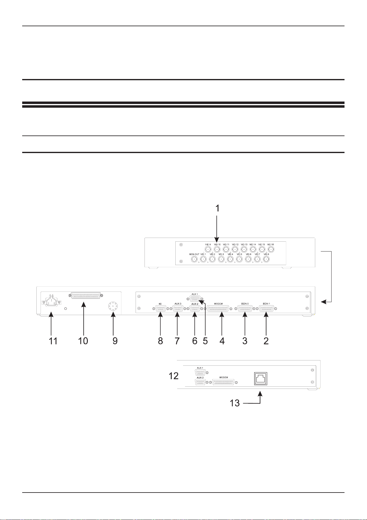
Fig: 1 Rear panel layout
WARNING: DO NOT CONNECT THE UNIT TO OTHER EQUIPMENT WITH POWER ON.
Key to Fig: 1
1 Cmaera Inputs 4 Modem 7 AUX3 10 Alarm Inputs 13 ISDN
2 ISDN 1 5 AUX 1 8 IIc Socket 11 Power Connection Connection
3 ISDN 0 6 AUX 2 9 Telemetry Out 12 Integral Dataflext TA Unit
Dedicated Micros Ltd Page 7
Page 20
Installation DVSTInstallationGuide
4.2 Power Inputs
The DVSTTransmitter ispowered via a standard mainsIEC cablewhich plugs intothe
rear panel. Power cable retaining clip prevents the cable from dropping out.
Thepowersupplyisselfadjusting to themainsinputandcanacceptavoltagefrom90to
260 volts.
Mains supply frequency can be either 50 or 60 cycles.
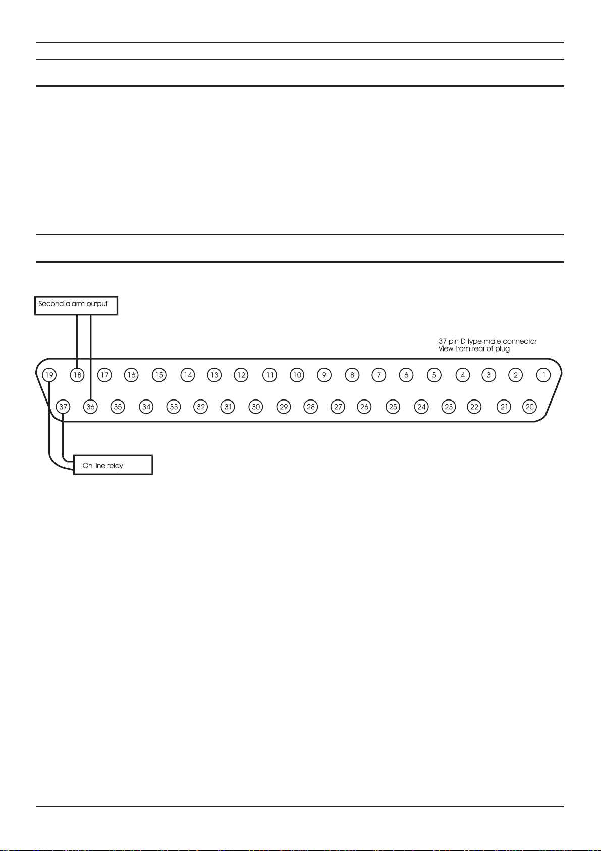
4.3 37 Way Alarm Connections
Fig: 2 Alarm input/output connections
Page 8 Dedicated Micros Ltd
Page 21

DVSTInstallationGuide Setup
5 Setup
5.1 What you require
Setup of the DVST DFT-0150 is undertaken using a PC (Personal Computer)
connected to the AUX0 port on the front panel.
To set up the DVST using a PC you will need the following:
A personal computer with an RS232 port.
A connection cable between the serial port of the computer and the serial port
(AUX3) of the DVST unit. (Details are in the cable section of this manual)
AsuitablecommunicationsprogramforyourPCthatcanoperateat9,600baud.
i.e. Procomm.
5.2 Setup using a PC
Procedure:
Turn off the power supply to the DVST and the PC.
Connect the two units together using a serial cable.
Power up both DVST and the PC then start the communication program.
Make sure that the speed and protocol of the communications program are as
follows:
Baud Rate=9,600
Parity=None
Data Bits=8
Stop Bits=1
Local setup mode can be entered by typing “ +++<ret>” or for MCI commands<ESC>
M\Setuponthekeyboard.TheDVSTcommandswillappearonthescreenofthePC.
If a password has been set the screen will go blank and the prompt PASSWORD> will
appear on the screen and a valid password must be entered followed by pressing the
<ENTER> key. If this enteredcorrectly the prompt CMD> will appear on screen. More
details on the operation of passwords appear later in this manual.
Typing HELP and pressing the <ENTER> or return key will list all the available DVST
commands.These are listedwithbrief descriptions toassistusers familiar withsetup of
theDVST.Allthesecommandsareexplainedindetailwithinthemanual,andhavebeen
grouped in a logical order to make set up of the DVST easy.
Typing VIEW andthen pressing<ENTER> willlist the presentsettings ofthe DVST.To
exit the SETUP mode type QUIT then <ENTER>.The DVST will then return to normal
operation.
Dedicated Micros Ltd Page 9
Page 22

Setup DVSTInstallationGuide
5.3 Remote Setup
RemoteDVST unitscan alsobeset upin the samemanner asalocal DVST.The same
procedure should be followed when the DVST is on line to a remote unit. When the
SETUP key is pressed the screen will go blank and the command prompt REM> will
appear on screen.
Proceed as for the local system.
Note: A PC cannot initiate remote set up with the “+++” command.
5.4 DVST Commands
Most commands aretyped indirect andterminated bypressing the<ENTER> keyon a
PC.
HELP
Note: Paragraphs 4.6 onwards detailthe command information listed by thehelp option and
have been grouped together in thelogical order thatshould be used when setting up a
DVST system.
QUIT
This returns the DVSTto normaloperation. Ifa MODEMis connected
and the DVST is set to MODEM=ON the initialisation strings will be
sent to the MODEM.
RESET
This command is used to completely reset the DVST system.
(All values are reset to their default values.)
Lists all commands available.
Exits the SETUP mode.
Resets DVST to factory defaults
Note: These values are stored in an integrated circuit called an EEPROM. This is not
dependent on a battery backup and will retain its settings indefinitely without a power
supply.
VIEW
This will display all the current DVST settings.
Page 10 Dedicated Micros Ltd
Display current DVST settings
Page 23

DVSTInstallationGuide Setup
5.5 Define Camera Inputs
MAX=nn
COL=nn
MON=nn
CAMnn=
Sets maximum number of cameras
(default, 8)
Range is 1 to 16.
Correct settings of this ensures that any receiving station does not
spend time trying to collect invalid camera inputs.
Set camera to Colour
Set camera to Monochrome
(default, all cameras set to colour)
Format is COL=01, COL=05 etc.
Format is MON=06, MON=15 etc.
It is important that camera inputs are correctly defined as colour or
monochrome.
Set camera title nn to ...
(default, Camera 01=CAMERA 01 etc.)
Format is CAM01=FRONT DOOR
5.6 Auxiliary Port 3
The auxiliary port 3 on theDVST can be used for programming theDVST with a PC or
for generating printer reports. Protocol is RS232 8 characters, no parity, one stop bit,
default at 9,600 baud.
AUX=
TERM is for terminal operation, control by PC.
PRINT operates as a printer connection.
MCI is for machine control interface.
DTMF is used to echo telemetry codes at the port.
ENG is used to display debug.
NULL turns the port off.
Note: Altering this command from aPC isvalid, butafter changingthe settingthe PCit willno
longercommunicate withtheDVST. Thereasonis thattheport hasnowbeen assigned
a different task. .
Set AUX port usage:
TERM, PRINT, MCI, DTMF, ENG, NULL
(default, ENG)
Dedicated Micros Ltd Page 11
Page 24

Setup DVSTInstallationGuide
5.7 Define Auxiliary Ports 1,2, 3
The auxiliary ports 1, 2, 3 on the DVST can be configured to operate with additional
equipment i.e. printers, telemetry equipment and PC based conrol systems (MCI).
PORT=
Set PORT usage,
(Each field entry is separated by a space. If the
commands are entered correctly the new settings will
be displayed):
<AUX PORT> <BAUD RATE> <PARITY>
<DATA BITS> <STOP BITS> <FORMAT>
(default settings )
AUX1 N 8 1 38400 PKT
AUX2 N 8 1 38400 DATA
AUX3 N 8 1 9600 ENG
AUX PORTAUX1, AUX2, AUX3
BAUD RATE1200, 2400, 4800, 9600, 19200, 38400
PARITYN (None) O (Odd) E (Even)
DATA BITS5, 6, 7, or 8
STOP BITS1 or 2
FORMAT
Aux1DATACharacter based data operation
PKTPacket based operation
BLKBlock data operation
NULLTurn off port
Aux2DATACharacter based data operation
NULLTurn off port
Aux3TERMTerminal operation
PRINTSerial printer connection
MCIMachine control interface
DTMFSend telemetry codes to port
ENGDisplay debug messages
NULLTurn off port
Example
PORT = Aux3<space>9600<space>N<space>8<space>1<space>Term <return>
Page 12 Dedicated Micros Ltd
Page 25

DVSTInstallationGuide DemonstrationMode
6 Demonstration Mode
Thisis providedto allow twoDVST unitstobe connectedback tobackwithout theneed
for connection to MODEMs or Terminal Adapters.
Aspecialdemonstrationcableisused,detailsofthisareexplainedlaterinthechapter.
6.1 Demonstration mode
DEMO=
Turns the demonstration mode on or off. The demonstration mode is
quit if the power to the DVST is turned off.
Note: ISDN must be set to Direct Mode
Turn the demonstration mode ON / OFF
Dedicated Micros Ltd Page 13
Page 26

DemonstrationMode DVSTInstallationGuide
6.2 Demo Cable
This cable allows two DVST units to be connected back to back without the need for
connection to MODEMs or Terminal Adapters.
Fig: 3 Wiring details for demo cable
Tech Note:
This is a synchronous balanced transmission. Transmit and receive lines therefore
cross yet maintainpolarity. The flying lead is used to source aclocking signal from the
MODEM port.
Page 14 Dedicated Micros Ltd
Page 27

DVSTInstallationGuide DemonstrationMode
6.3 Connecting the demo cable
Single cable operation
The cable connects PORT 0 on the transmit unit to PORT 0 on the receive unit. The
small flying lead connects to the MODEM port on the receive unit.
Fig: 4 Demo cable connections
Dedicated Micros Ltd Page 15
Page 28

DemonstrationMode DVSTInstallationGuide
This page intentionally blank
Page 16 Dedicated Micros Ltd
Page 29

DVSTInstallationGuide Modems
7 Modems
7.1 PSTN Connection (Modem)
Connection to a PSTN telephone line is via a modem and modem port.
7.2 MODEM Commands
MODEM=
The MODEM= command controls three distinct parameters.
Tech note: Thereasonisas follows;ifsetto ATMODEtheDVST attempts tocommunicatewith the
MODEM when starting up, exiting set up mode etc. The DVST will wait a set period of
timefor repliesbefore givingup. This willconsiderably slowthe system ifno MODEMis
attached.
Sets MODEM operation, three parameters:
OFF
(default, OFF)
DIRECT, ATMODE
(default, ATMODE)
The DIRECTmode is used if the MODEM has its telephone numbers
stored internally and the DVST does notpass telephone numbers for
dialling.
The ATMODE is most often used. The DVST passes numbers from
the dial menu to the MODEM which then initiates a call.
Dedicated Micros Ltd Page 17
Page 30

Modems DVSTInstallationGuide
SYNC
Thesync orsynchronousmode relieson the modemgenerating clock
signals to the DVST.
MODEM
Modem switches from the command mode CMD> to allow direct
controlofaconnected MODEM.Thespeedofcommunicationwiththe
MODEM will be as set with the MBAUD= command.
This is called transparent MODEM mode and is terminated by
pressing the ESCAPE or ESC key.
MBAUD=
MODEM2
Set MODEM port ASYNC baud rate.
(default, 19200)
9600, 19200, 38400
This command sets the speed of communication between the DVST
and the MODEM when AUX 1 is used for asynchronous mode. The
speed of communication in the Synchronous mode is determined by
the clock signal supplied by the MODEM.
ASYNC
Inthe asynchronous modetheMODEMcontrols theflowofdata using
RTS/CTS signals.
Modem switches from the command mode CMD> to allow direct
control of a connected MODEM through AUX 1. The speed of
communication with the MODEM will be as set with the PORT=
command.
This is called transparent MODEM mode and is terminated by
pressing the ESCAPE or ESC key.
PORT=
Refer Chapter Setup (Basic).
Page 18 Dedicated Micros Ltd
AUX1, 19200, N 8 1, MODEM2
Page 31

DVSTInstallationGuide Modems
7.3 Modem configuration strings
All MODEMsneed special configuration, depending on how theMODEM is tobe used
and how the DVST will interact with it.
Standard MODSTRset upsconfigure the MINIT and SREGstrings, theUSER string is
left free for any extra configuration that may be needed.
MODSTR=
Set type of modem: FAST or SYNC
(default, FAST)
This setting (shortened form of MODem STRings) automatically sets
up the DVST to operate with one of the three recommended
MODEMs.
FAST
This sets the MINIT and SREG strings for correct synchronous
operation with theMOTOROLA 326x VFAST MODEM.The MODEM
configuration strings are set up as follows:
MINIT=AT&M1 &D2 &C1 *FLO *AA1 *DTO *OC1
SREG=ATS10=30S25=0
SYNC
This sets the MINIT and SREG strings for correct synchronous
operation with the MICROCOM 4232bis MODEM. The MODEM
configuration strings are set up as follows:
MINIT=AT&M1 &D2 \GO \EO E1 &C1 \JO
SREG=ATSO=1
MOD2STR=
Set type of modem: FAST, SYNC, ASYNC or ZYXEL
(default, )ASYNC
FAST
This sets the MINIT and SREG strings for correct synchronous
operation with theMOTOROLA 326x VFAST MODEM.The MODEM
configuration strings are set up as follows:
M2INIT=AT&M1 &D2 &C1 *FLO *AA1 *DTO *OC1
SREG2=ATS10=30S25=0
Dedicated Micros Ltd Page 19
Page 32

Modems DVSTInstallationGuide
SYNC
This sets the MINIT and SREG strings for correct synchronous
operation with the MICROCOM 4232bis MODEM. The MODEM
configuration strings are set up as follows:
M2INIT=AT&M1 &D2 \GO \EO E1 &C1 \JO
SREG2=ATSO=1
ASYNC
This sets the MINIT and SREG strings for correct asynchronous
operation with the Trailblazer MODEM. The MODEM configuration
strings are set up as follows:
M2INIT=ATSO=1 &C1 &K3 E1 V1 &MO
SREG2=ATS7=60 S10=7 S37=7
~S50=255 ~S51=5 ~S52=1 ~S110=0 ~S104=0
USER=...
SEND
ZYXEL (US Modems Only)
This sets M2INIT and SREG2 for the correct synchronous operation
with the ZYXEL modem. The modem configuration strings are set up
as follows:
M2INIT=AT&M1&D2&C1&H0
SREG2=ATS10=30 S0=1
Available for user configuration
(Default, blank)
TheUSER stringisfor anyextracommands that theuser may needto
send to the modem in addition to the MINIT and SREG settings.
Send current modem configuration
This transmits the information contained in the MINIT, SREG and
USER strings to the MODEM.
Althoughthiscommandcanbeissuedfromthecommandmodeatany
time, it is also invoked at the termination of any call and when the
command mode is exited with the QUIT command.
Page 20 Dedicated Micros Ltd
Page 33

DVSTInstallationGuide Modems
DIAL=
Modem dial string
(default, ATDT)
This isthe commandthat mustprecede allnumbers that the MODEM
has to dial. Typically the MODEM will dial using either pulse or tone
dialling. This is dependenton thetelephone exchangethe MODEMis
connectedto,mostmodern exchangesareabletoaccepttonedialling
which is faster than the older pulse dialling method.
For tone dialling: DIAL=ATDT
For pulse dialling: DIAL=ATDP
Tip: Extra information can be linked to the above commands, internal exchanges that
require a“9" to bedialled to access outside lines can have thisadded to thedial string,
typically ATDT9.
7.4 Modem Operation
All modern modems respond to a set of “Hayes” commands. There are several
differences in these commands from manufacturer to manufacturer. It is important to
use the correct commands with each modem and not to attempt to use one
manufacturer’s set up with another manufacturer’s modem.
If possible modems should be linked to DVST in the synchronous mode. Some
modems, forexample those usingPEP (Packet EnsembleProtocol), can onlybe used
in the asynchronous mode.
Cablesfor connection tosynchronousandasynchronous modemsaredifferentand are
not interchangeable. Refer to the Cable Assemblies chapter for further details.
Dedicated Micros Ltd Page 21
Page 34

Modems DVSTInstallationGuide
7.5 Connecting a modem in direct mode
This mode uses a modem in a ‘dumb’ mode, and purely relies on thehardware control
lines.Telephonenumber selection, andallotherconfigurationmust be performedatthe
modem.
The modem is controlled using DTR (Data Terminal Ready), and indicates it’s status
using DCD (Data Carrier Detect).
Note: This mode is not recommended, easier operation is achieved in ATMODE.
Call request
A call is requested by making DTR active (high). At this point the MODEM dials it’s
stored number, and attempts to establish the call with the remote end. When the call
connecthas beencompletedthe modemraisesit’s DCD line,confirmingit isconnected
with the remote location.
A call already being active is indicated by the DCD line being active (high) from the
MODEM.
Call answer request
Ifa callisincoming, the modemanswersthe call,establishesthe physicallink,and then
raisesDCDtoinformtheDVSTunitthat a call ispresent.TheDVSTunitrespondstothis
by taking DTR active (high).
Call disconnect.
This isrequested bydropping the DTR signal. Asuccessful disconnectis confirmed by
the DCD line being dropped by the MODEM. In this mode the DTR line remains low.
Configuration of modem in direct mode
Noconfigurationcan beperformedbythesystem, howeverthefollowingarerequired of
the modem :
Select synchronous operation.
Dial stored number on low to high transition of DTR.
Disconnect on a high to low transition of DTR.
DCD must follow remote carrier.
Ignore DTR to answer.
Auto-answer. ( If required ).
No flow control enabled.
Page 22 Dedicated Micros Ltd
Page 35

DVSTInstallationGuide Modems
7.6 Using a modem in ATMODE
InthismodetheHayessetofcommandsisused,allofwhichbeginwiththelettersAT.
Both call setup and configuration are performed using these commands.
The commands can be configured on the DVST unit in setup mode.
The modem is also controlled using DTR (Data Terminal Ready), and indicates it’s
status using DCD (Data Carrier Detect).
Call request
The DTR is normally active, unless the modem channel is turned off, or the unit is in
setup mode.
Todial acallthesystem sendsthedial string (setbyDIAL= intheDVSTsetup menu)to
the modem, followed by the number selected.
For synchronous operation the modem switches tosynchronous mode on connection.
Whenthecallconnecthasbeencompleted the modemraisesit’sDCDline,confirmingit
is connected with the remote location. A call already being active is indicated by the
DCD line being active (high) from the modem.
Call answer request
If acall is incoming,and the DTRline is high,the modem answersthe call, establishes
the physical link, and then raises DCD to inform the DVST unit that a call is present.
Call disconnect
This is requested by a high to low transition on DTR. A successful
disconnect is confirmed by the DCD line being dropped by the modem.
In this mode the DTR returns high after a short delay.
7.7 General settings for modems in ATMODE
The modem is configured from the DVST unit using the following strings:
MINIT=general modem configuration.
SREG=typically used for setting of s-registers.
USER=optional string, typically for individual customisation.
DIAL=string used to dial, typically ATDT for tone dialling.
Theconfigurationdetails stored inMINIT,SREG&USERare sent onpower-up,leaving
setupmode,and on disconnectingacall.IfaMODEM is notpresentalargedelaywill be
experienced while the system waits for replies from the MODEM. To avoid this the
command MODEM=OFF should be selected from the DVST setup menu. It is also
possible totransmit or send these values to the MODEM using theSEND command in
setup.
It is also possible to communicate with the modem directly using the MODEM
command.
Dedicated Micros Ltd Page 23
Page 36

Modems DVSTInstallationGuide
MODEM Requirements
Although there are default settings for three MODEMs, other MODEMs can be
cofigured to operate with DVST.
As the settings vary from manufacturer to manufacturer there is not a set series of
commands that are guaranteed to work. The following tables detail possible
configurations, all should be checked against the MODEM manual. Before attempting
these suggested settings the MODEM should be reset to factory defaults with the
command AT&F or ATZ
The following settings are required as a minimum:
All modems:
Action required of MODEM Possible AT settings
DCD (Data Carrier Detect, sometimes abbreviated to
CD) must be set to follow the carrier. This signal
indicates to the DVST that a connection to another unit
has taken place.
The call must disconnect on a high to low transition of
DTR (Data Terminal Ready).
Only answer a call if DTR is present.
Auto-answer may be set if required. S0=1
Check MODEM manual
Echo commands. E1
&C1
&D2
Country specific
Synchronous Modems:
Extra action required of Synchronous MODEM Possible AT settings
Asynchronous mode must be set to dial the number
and the modem must switch to synchronous mode on
carrier detect.
Flow control must be disabled. &K0
Check MODEM manual
&M1
The modem should ignore RTS. &R1
Asynchronous Modems:
Extra action required of Asynchronous MODEM Possible AT settings
Asynchronous mode must be enabled. &M0
Flow control must be enabled on RTS/CTS. &K3
Error correction enabled ( if needed ). Refer to MODEM manual
Note Itisstronglyrecommendedthat oncethemodemhasbeenconfigured asabove,itisset
in such a mode that this configuration is recalled automatically on power up. This will
help to ensure correct operation aftera power failure. Consult you modem instructions
for details of how to achieve this.
Page 24 Dedicated Micros Ltd
Page 37

DVSTInstallationGuide Modems
7.8 MOTOROLA VFAST
Cable required to connect to DVST: (25 to 25 - V24 SYNC)
When installing the VFAST MODEM the following procedure should be
followed:
Connect the MODEM and DVST as in the installation chapter.
Power up the DVST (leave the MODEM without power).
Enterthesetupmodeandconfigurethe DVST for operationwiththeVFASTMODEMby
typing the command MODEM=ATMODE,MODSTR=FAST (default setting).
Power up the MODEM and wait for the self test to finish.
Type SEND then <ENTER>.
The DVST will program the MODEM.
It is good practice to store these values permanently in the MODEM.
Then the values will not be lost if power is removed from the MODEM.
To store these values proceed as follows:
User= AT&Y1&W1 <return>
Send <return>
Moden displays <save completed>
The MODEM will then always power up with the correct operational configuration.
Country specific settings
The answeron number ofrings command *AA1is not validin some countries (France,
xx) and the MINIT string should be reprogrammed with the value *AA2.
The MINIT string is programmed as:
MINIT=AT&M1 &D2 &C1 *FLO *OC1 *DTO *DE12 *AA1
Dedicated Micros Ltd Page 25
Page 38

Modems DVSTInstallationGuide
No Dialtone
In some cases the MODEM will not recognise the prescence of a dial tone from the
exchange. The following codes will allow blind dialling and if these are needed
permanently they should be followed by:
User=ATX3*BDO&Y1&W1 Where
ATX3 is Dial blind without presence of dial tone
*BD0 Wait two seconds before dialling
&W1 Store above settings in option 1
&W1 Power up using these settings
Note: This feature is country specific and may not be available in some versions of the
MODEM’s software. Please refer to the literature supplied with your MODEM.
Transmission speed
TheMODEMcanbealittle ambitious insettingthelinespeed.Itislikelythatalinkwillbe
establishedat a higherspeedthan the linecansupport without anunacceptablelevel of
errors.
Inthesecasesitmaybenecessarytolimitthespeedoftransmissionuntilareliable point
is reached.
Maximum line speed may be set by the command:
AT*MXn
where the value for n equals following baud rate applies:
13 =28800
12 =26400
11 =24000
10 =21600
9 =19,200
8 =16,800
7 =14,400
6 =12,000
5 =9,600
4 =7,200
3 =4,800
2 =2,400
1 =1,200
0 =300
To limit the speed of transmission to 14,400 use AT*MX7. This could be stored in the
USER= string.
Page 26 Dedicated Micros Ltd
Page 39

DVSTInstallationGuide Modems
7.9 Microcom V3242
Cable required to connect to DVST 25to25 (Part No.AS-DVST-SYNC)
Syncronous mode :
&M1Dial async, switch on connect.
&D2Hangs up with on to off transition of DTR - needed for auto answer.
\G0Disables modem flow control.
\E0Do not echo data !
E1Echo commands.
&C1CD follows carrier.
\J0Turn off baud rate adjust.
DIP Switch Settings Synchronous Operation
Front panel switches Rear panel switches
Dedicated Micros Ltd Page 27
Page 40

Modems DVSTInstallationGuide
7.10 Trailblazer
Cable required to connect to DVST 9to25 (Part No. AS-DVST-ASYNC)
Async mode
Trailblazer in Conventional Command mode.
&C1CD follows carrier.
&k3RTS/CTS flow control.
E1Echo commands
V1Textual result codes
&M0Async mode
s7=60Wait 60 seconds for carrier.
s10=7Carrier loss to disconnect time.
s37=7Attempt to connect in PEP mode.
~s50=255Operate in PEP mode.
~s51=519200 bps operation.
~s52=1Modem hangs up on DTR, only autoanswer on DTR.
~s110=0PEP data compression disabled.
~s104=0Disable auto dialling.
Page 28 Dedicated Micros Ltd
Page 41

DVSTInstallationGuide Modems
7.11 OCTOCOM OSI 8196A
Cable required to connect to DVST 25to25 (Part No. AS-DVST-SYNC)
Manufacturer:
Octocom Systems, Inc.
One Executive Drive
Chelmsford,
MA 01824
USA
No DIP switches are used.
A single DATA push button on the front panel serves to unhook the
modem.
When the modem is unpacked and used for the first time the CD line
is held on. This means that the DVST unit believes that there is an
incoming call and waits for data.
Proceed as follows to clear this condition:
Wait for the DVST unit to time out
and then press <SETUP>
At the command prompt CMD> typeMINIT= <RET>
At the command prompt CMD> type SREG= <RET>
At the command prompt CMD> type USER=AT <RET>
At the command prompt CMD> type SEND <RET>
Wait for the information to be sent to the modem.
At the command prompt CMD> type MODEM <RET>
The unit will reply - Modem Mode
Type AT <RET>
The reply from the modem is “OK”
Type in the following, AT&M1&C1&D2&K0&R1<RET>
The reply from the modem should be “OK”, if the reply
is “ERROR”, try again.
Type AT&W
The modem will now power up without the CD line held on.
Press the <ESC> key to exit modem mode.
At the command prompt CMD> type. MINIT=&M1 &C1 &D2 &K0 &R1.
&M1Dial async, switch to sync on connect.
&C1CD follows remote carrier.
&D2 Hangs up with on to off transition of DTR - needed for auto answer.
&K0Modem flow control is disabled.
&R0Modem iignores RTS, CTS is on when the modem is online.
Dedicated Micros Ltd Page 29
Page 42

Modems DVSTInstallationGuide
This page intentionally blank
Page 30 Dedicated Micros Ltd
Page 43

DVSTInstallationGuide TerminalAdapters
8 Terminal Adapters
TA(s) or Terminal Adapters allow the DVST to communicate over digital ISDN
telephone lines.
8.1 ISDN Connection (Terminal Adapter)
Connection to an ISDNline isvia aterminal adapterand Port0. Onsystems usingdual
ISDN lines both Port 0 and Port 1 should be connected.
The type of cable required to connect to the terminal adapter can vary.
DUALISDN=
...Sets dual ISDN support ON or OFF
(default, on)
ISDN=
...Sets ISDN for ATMODE, DIRECT, X21 mode
(default, ATMODE)
DIRECT
DIRECT mode relies upon the terminal adapter dialling a stored
number ora network only accessing a single remote point. Also used
for Demo mode (chapter 7)
ATMODE
ATMODE refers toHayes ATdialling wherethe numbersto bedialled
are storedin theDVST dialling menu,also usedfor Dedicated Micros
Terminal Adaptor TA04
Dedicated Micros Ltd Page 31
Page 44

TerminalAdapters DVSTInstallationGuide
X21
Uses X21 dialling for numbers in the DVST menu
Connection canbe madein thedirect mode,where thenumber tobe called is stored in
theterminal adapter,orin the X21diallingmode wheretheDVST passesthenumber to
be dialled to the Terminal Adapter, or ATMODE.
V35
V35=ON/OFF
Applicable in all modes (ATMODE, DIRECT and X21)
8.2 Connecting a terminal adapter in direct mode
Thisusesthesignallinglines;C(control)andI(indicate),torespondtoandinitiatecalls.
Making a Call
The DVST initiates a call by raising C
The TA then dials its stored number
When the call is connected the TA raises I
Call continues
Answering a Call
The TA indicates an incoming call by raising I
The DVST responds by raising C
Call continues
Call disconnection
The DVST ends a call by dropping C
The TA confirms disconnection by dropping I
Configuring a Terminal Adapter for direct mode operation
AsthecontrollinesI&Careusedtocontrolcalls,thefollowingisrequiredofthesystem:
Answer : C
Originate : C
Disconnect : C
Alerting : I
DCD/I : Delay
Note: The above settings are the basic requirements. TAs have many other settings which
can affect transmission such as speed of call, type of call, circuit switch etc.
Page 32 Dedicated Micros Ltd
Page 45

DVSTInstallationGuide TerminalAdapters
8.3 Gandalf TA1
Cable required 15 to 25 (2 of Part No. AS-DVST-TA1)
The Gandalf TA1 is a dual port unit capable of simultaneiusly using both ISDN B
channels on an ISDN2 connection.
The Gandalf hastwo X21ports, PORT0& PORT1.They mustbe configuredas follows
for DIRECT connection:
Direct Connection
Configure the Gandalf as follows:
CALL MODE=CKT SWITCH AUTO
CALL TYPE=BOTHWA
CALL SPEED=NEGOTIATE
ANSWER=C
ORIGINATE=C
DISCONECT=C
ALERTING=I
DCD/I=DELAY
Y
Dedicated Micros Ltd Page 33
Page 46

TerminalAdapters DVSTInstallationGuide
8.4 ASCOM 5000 / CITAM
ATMODE
Cablesrequired -2x15 to15 (PartNo.AS-DVST-X21). Dipswitchsettings canbeused
and should be set as follows:
Note: Switch 3 selects the sub address, if used.
Fig 5: ASCOM internal dip switch settings (ATMODE)
Step Instruction Remarks
1 Using the pull handle, remove the
circuit board module from the Citam
5000
2 Adjust the dip switches as shown in
Figure 9
3 Press the select key four times so
that the legend ‘CONF’ appears on
the display.
4 Press the enter key once and it will
say ‘PRT1’, press the select key
twice it will say ‘TA’, press the enter
key it will say ‘SHOW’.
5 Press and hold select until the
display reads ‘CHNG’, remove your
finger from the select key and press
the enter key, ‘INDB’ will be
displayed.
6 Presstheenter key, themessage will
be ‘ON’, use the select key to turn
this to ‘OFF’, then press the enter
key.
TheCitamwillnowperformaselftest.
On completion the display will read
ISDN.
7 Hold the select key and press the
enter key, the display will return to
‘CONF’.
8
Page 34 Dedicated Micros Ltd
At ‘CONF’ press the enter key, the
display will read ‘PRT1’ for port 1.
This has turned of the in-band test
feature of the unit.
Page 47

DVSTInstallationGuide TerminalAdapters
Step Instruction Remarks
9 Press the enter key, it will read
‘SHOW’. Hold the select until this
changes to ‘CHNG’, press the enter
key, display willthenshow ‘DIPS’ for
dip switch.
10 Press the enter key, it should read
‘INAC’ for inactive, press the select
key to change this to ‘ACTV’ for
active,presstheenterkeytoreturnto
‘DIPS’.
11 Hold the select key down and press
the enter key, this will return unit to
‘CONF’.
12 Press the enter key and the display
willread ‘PRT1’,press the selectkey
to change this to port 2.
13
14 Press the enter key it will change to
15 Hold the select key and press the
Press the enterkey and ‘SHOW’ will
appear, hold the select key for three
seconds, the display will change to
‘CHNG’.
‘DIPS’, pressthe enterkey and itwill
say ‘INAC’, pressthe select key and
‘ACTV’ will be displayed, press the
enter key and display will return to
‘DIPS’.
enter key, returning the display to
‘CONF’.
SEND CONFIGURATION STRING
16 At the command prompt CMD> type
ISDN=ATMODE <RET>
DUALISDN=ON <RET>
ISDNSTR = CITAM <RET>
At the command prompt CMD> type
SEND <RET>
Wait for the information to be sent to
the modem.At the commandprompt
CMD> type
ISDN0 <RET>
AT<RET>
AT&W<RET>,
<ESC>
ISDN1<RET
AT<RET>
The unithas nowhad the dip switches
made active on both ports 1 and 2.
Dedicated Micros Ltd Page 35
Page 48

TerminalAdapters DVSTInstallationGuide
AT&W<RET>
<ESC>
QUIT <RET>
The Citam is configured to operate on DVST.
X21
Cables required - 2x15 to 15 (Part No. AS-DVST-X21)
Fig 6: ASCOM internal dip switch settings (X21)
Dip switch settings can be used and should be set as follows:
Note: Switch 3 selects the sub address, if used
These commands are entered using
SetupMode ontheDVST0200 unitvia
a PC. Refer to Chapter para
Step Instruction Remarks
1 Using the pull handle, remove the
circuit board module from the Citam
500
2 Adjust the dip switches as shown in
Figure 10
3 Press the select key four times so
that the legend ‘CONF’ appears on
the display
4 Press the enter key once and it will
say ‘PRT1’, press the select key
twice it will say ‘TA’, press the enter
key it will say ‘SHOW’
5 Pressthe holdselect until thedisplay
reads ‘CHNG’ remove your finger
from the select key and press the
enter key, ‘INDB’ will be displayed
6 Press theenter key, themessage will
be‘ON’,usethe select keyto turn this
to ‘OFF’, then press the enter key
7 Hold the select key and press the
enter key, the display will return to
‘CONF’
8
At ‘CONF’ press the enter key, the
display will read ‘PRT1’ for port 1
The Citam will nowperform a self test
On completion the dispaly will read
ISDN
This has turned off the in-band test
feature of the unit
Page 36 Dedicated Micros Ltd
Page 49

DVSTInstallationGuide TerminalAdapters
Cont.
Step Instruction Remarks
9 Press the enter key, it will read
‘SHOW’. Hold the select until this
changes to ‘CHNG’, press the enter
key, displaywill thenshow ‘DIPS’for
dip switch
10 Press the enter key,it should read
‘INAC’ for inactive, press the select
key to change this to ‘ACTV’ for
active,presstheenterkeytoreturnto
‘DIPS’
11 Hold the select key down and press
the enter key, this will return unit to
‘CONF’
12 Press the enter key and the display
willread ‘PRT1’,press the selectkey
to change this to port 2
13
14 Press the enter key it will change to
15 Hold the select key and press the
Press the enterkey and ‘SHOW’ will
appear, hold the select key for three
seconds, the display will change to
‘CHNG’
‘DIPS’, pressthe enterkey and itwill
say ‘INAC’, pressthe select key and
‘ACTV’ will be displayed, press the
enter key and display will return to
‘DIPS’
enter key,returning the dispaly to
‘CONF’
The unithas nowhad the dip switches
made active on both ports 1 and 2
The Citam is configured to operate on DVST.
Dedicated Micros Ltd Page 37
Page 50

TerminalAdapters DVSTInstallationGuide
8.5 Dataflex TA
The Dataflex terminal adaptor
Cable 2 x 15 to 15 way (X21 Cable Assembly refer to page )
When connected to or supplied with a Dataflex Terminal Adaptor the DFT0150will
automatically configure itself for this type of operation. Ensure all terminal adaptor
conections are made BEFORE power up, on power up the DFT0150 will send its
configuration string to the terminal adaptor. The following is provided for information
only.
These commands are entered using Setup Mode on the DVST0150 unit.
SEND CONFIGURATION STRING
1 At the command prompt CMD> type
ISDN=ATMODE <RET>
At the command prompt CMD> type
ISDNSTR =DATAFLEX <RET>
Wait for the information to be sent to
the modem.
At the command prompt CMD> type
DUALISDN=ON <RET>
SEND <RET>
ISDN0 <RET>
AT <RET>
AT&W <RET>
<ESC>
ISDN1 <RET>
AT <RET>
AT&W <RET>
<ESC>
At the command prompt CMD> type
QUIT <RET>
The Dataflex TA is now configured for use with the DVST0150.
Page 38 Dedicated Micros Ltd
Page 51

DVSTInstallationGuide LeasedLineTransmission
9 Leased Line Transmission
Leased line transmissionis generallyused whena dedicatedor privateline isavailable
to connect the transmit and receive units.
There are many different types of leased line, 2 wire and 4 wire, with many variants
depending on what is offered by the PTT companies.
Most conventionalModems can operate on leased lines althoughthe cables will differ
from those used on a standard telephone connection.
Baseband Modems offer faster transmission rates over standard Modems and an
example using one of these is given at the end of this chapter.
9.1 Leased line terminology
In leased line terms the receiver or calling unit is set as ORIGINATE.
The transmit unit is set to ANSWER.
9.2 DVST set up for leased line operation
Whenleasedlineoperationis selected, thetypeof transmission selected(via the X21or
the V24 port) is determined by the dial type set in telephone number 0.
If telephone number 0 is set to MODEM, the V24 or Modem port will be used. If either
ISDN 0 or 1 is specified, X21 ports 0 or 1 will be used.
LEASED=
Leased line operation, options are:
(default, OFF)
Dedicated Micros Ltd Page 39
Page 52

LeasedLineTransmission DVSTInstallationGuide
ORIGINATE
The Receiver unit is set to originate.
ANSWER
The Transmitter unit is set to answer.
OFF
This disables the leased line feature.
9.3 Leased line operation
Whenleasedlineoperationhasbeenset up, the DVSTwillattempt to communicate with
aremotesitewhenclocksarereceived.Thisdoesnotrequirehardwarehandshaking.
If the line is broken for any reason, the units will attempt to reconnect and when
commuunicationisrestoredwillautomaticallyestablishvideotransmissionofimages.
The units can be disconnected (taken off line) by pressing the LINE key. Pressing the
LINE key again will establish image transmission.
Page 40 Dedicated Micros Ltd
Page 53

DVSTInstallationGuide LeasedLineTransmission
9.4 ASCOM 64000 Baseband Modem
The am-64000 is a good alternative to using a conventional PSTN MODEM in leased
line mode.it also has a greater data transfer rate for short or private wire connections,
the speed is 64kbps for the AM-64000 and 128kbps for the AM-128000, the max
distance between the two units is 14 kilometres on a 0.64 mm cable or a -50 db loss.
Set Both Dvst Units In The Direct Mode
Using the cursor keys on the front of the ASCOM unit set the system up as follows.
SET UP TX OR MASTER END
RATE MENU64K
OPTION MENUX21
CONFIGURATION MENUMASTER MODE
HIGH RATE
X21 LOOPS OFF
BIT SYNC
64K MODE OFF
POWER 0 dBm
MENU UNLOCKED
SET UP RX OR SLAVE END
OPTION MENUX21
CONFIGURATION MENUSLAVE MODE
HIGH RATE
X21 LOOPS OFF
POWER 0 dBm
MENU UNLOCKED
Connect both units to the line and confirm that the status menu reads C=off and I=on.
This confirms the units are in communication.
Dedicated Micros Ltd Page 41
Page 54

LeasedLineTransmission DVSTInstallationGuide
This page intentionally blank
Page 42 Dedicated Micros Ltd
Page 55

DVSTInstallationGuide Calls
10 Calls
10.1 Passwords
Passwords canbe set andused by thesystem. When aPASSWORD is setit provides
protection for the system at two points:
1)Whenevera remote systemcalls itmust sendthe correctpassword, otherwise
no connection will be established.
2) Wheneverthe SETUP keyis pressed, thepassword will berequested before
the setup mode is entered.
Method:
Enter SETUP mode is by pressing the SETUP key on either keyboard.
Ifa passwordhasbeen set thescreenwill goblankand the promptPASSWORD
willappearonthescreen.Atthis point avalidpasswordmust be entered followed
by pressing the <ENTER> key. If this entered correctly the prompt CMD will
appear on screen.
PASSWORD=
The systempassword can beup to 10 alpha numeric, case sensitive,
characters. Once this has been set only calling units that have the
associated password linked tothe telephone number can access the
system.
PASSn=
Set system password to ...
Set telephone entry n password to ...
Range is 0 to 19
This islinked tothe designatedtelephone numberand is the keyword
that willunlock the remote system thatis being called.It maybe up to
10 alpha characters in length.
Format: PASS4=BERLIN
In the above case the system called would have the password set to
BERLIN. Only then could the system be accessed.
Default: None set
Dedicated Micros Ltd Page 43
Page 56

Calls DVSTInstallationGuide
SPASSWORD=
This feature allows an additional password to be allocated just to
provide security for the set up mode. This can be used to prevent a
remote user accessing the system and altering the settings.
Default: None set
Note: To maintain security, passwordscannot beread backfrom thesystem. Careshould be
taken to ensure passwords are not lost as this will require a new EEPROM chip to be
fitted to the DVST.
Set SETUP password to ...
10.2 On Screen Titling
SYSTEM=
This is a 30 character title which appears on the front screen of the
DVST. When a transmitter sends to a receiver this title is transferred
from the transmitter and appears on the baseline of the receiving
monitor.
Set system ID string to ...
TIME=
The time is based on the 24 hour clock. 4 digits must be entered.
DATE=
Date is always set as a six figure format.
Twooptionalmessagesare superimposed oncamera images sentfrom thetransmitter.
The first is the camera title and the second is the time and date.
TLPOS=
Set current time in HHMM format
Set current date in DDMMYY format
Set camera title position
(default, 1)
Whentheimagesare transmitted thecamera title appearsat the topof
the screen. This setting adjusts the height of the camera title.
TDPOS=
Set clock screen position
(default, 11)
When the images are transmitted the time & date appears at the
bottomof thescreen. Thissettingadjusts theheight of thetime &date
information.
Note: The range available for both TLPOS and TDPOS is from 1 to 11, 1 is at the top of the
screen and 11 at the bottom. Settings for TLPOS and TDPOS should be 2 numbers
apart to avoid overlap. Setting either value to 0 removes the text from the screen.
Page 44 Dedicated Micros Ltd
Page 57

DVSTInstallationGuide Calls
10.3 Telephone Number Entries / Connection Commands
TELn=
Set telephone entry n to ...
(default, blank)
Twenty telephone numbers can be stored in memory.
Format: TEL2=01044617944965
If the MODEM or ISDN Terminal Adapter is to work in the DIRECT
mode, the entry can be left blank.
Telephone number 0 is the default number dialled when alarms are
used toinitiate acall to another system. Thefall backnumber if thisis
engaged is always stored in telephone number 1.
Where a number is used with dual ISDN dialling it is automatically linked with that
number plus 10. Therefore Tel number 4 & 14 would be dialled if dual ISDN was
selected for that telephone number.
TELn
Set telephone entry n as current
TYPEn=
This selects thenumber thatwill bedialledinitially ifthe up/downkeys
are not used to select another.
Format: TEL2
Set telephone entry type to dial via ISDN0, ISDN1,
ISDNx2 (dual), or MODEM
(default, ISDN0)
Each of the telephone numbers can be linked to either a PSTN
MODEM or an ISDN terminal adapter.
Thiscommanddetermineswhichoftheexternalports(MODEM,ISDN
Port0,orISDNPort1)will be used whena particular telephone number
is selected.
Format:
TYPE0=ISDN0
TYPE1=ISDN1
TYPE2=ISDN2
TYPE3=MODEM
TYPE4=MODEM2
Example: TYPE5=2
Sets Telephone entry 5 to ISDN2
Dedicated Micros Ltd Page 45
Page 58

Calls DVSTInstallationGuide
TIMER=
DIALCLR=
10.4 Callback
This feature allows an operator to dial a remote unit and then have that unit
automaticallycalltheoperatorback.Thiscanbeausefulsecurityfeature.Theoperation
of callback is as follows:
Local unit calls remote unit.
Call connects.
Localunitpassesthedialmenunumber(0to9)thattheremoteunitwillcallback.
Call disconnects.
The local unit waits for a return call.
Remote unit waits for ten seconds then calls local unit.
Local unit answers and contact proceeds as normal.
Call connection timeout period
(default, 60 seconds)
Thisis the periodoftimethat the DVSTwillwaitwhile tryingto connect
acall. Thiswill varydependingon thetype ofcall(ISDN orPSTN) and
as there may be a delay in establishing International calls, the timer
value should be increased.
...Sets time dial menu remains on screen
(default, 30 seconds)
CALLBACK=
Set call back ON or OFF
(Default, off)
When the callback feature is switched on the option appears on the
dialling menu to make either a normal call or a remote callback call.
Normal call isthe default and this is highlighted. By using theleft and
right arrow keys remote callback can be selected and deselected.
Note: Callback must be enabled on BOTH the transmit and receiving units
Page 46 Dedicated Micros Ltd
Page 59

DVSTInstallationGuide ImagesandTransmission
11 Images and Transmission
Screen display - Periscope mode
CAMLO=Sets low resolution cameo operation:
Options are:
QUADHIHigh resolution quad size image
QUADLOLow resolution quad size image
CAMHISixteenth screen size high resolution
Default:
QUADLO
11.1 Image size
Target image size =
In the different screen modes of DVST each image is compressed to a target size and
then transmitted.
Target Picture Sizes :
SIZEFHI=Set target size (K):FULL HI RES
SIZEFLO=FULL LO RES
SIZEQHI=QUAD HI RES
SIZEQLO=QUAD LO RES
SIZEMULT=MULTISCREEN
DUALFHI=As above but for dual isdn operation
DUALFLO=
DUALQHI=
DUALQLO=
DUALMULT=
SIZEFHI =20000(20000 Maximum)
SIZEFLO =12000(12000)
SIZEQHI =8000( 8000)
SIZEQLO =4500( 4500)
SIZEMULT=2500( 2500)
DUALFHI =20000(20000)
DUALFLO =14000(14000)
DUALQHI =8000( 8000)
DUALQLO =4500( 4500)
DUALMULT=2500( 2500)
Dedicated Micros Ltd Page 47
Page 60

ImagesandTransmission DVSTInstallationGuide
This page intentionally blank
Page 48 Dedicated Micros Ltd
Page 61

DVSTInstallationGuide Alarms&Events
12 Alarms & Events
12.1 Purpose & intended use
Alarm devices connected to DVST transmission products are intended to allow
verification and response to remote events.
12.2 Alarm Connections
Alarm connections are made via a 37 pin D type male connector which plugs into the
side panel of the DFT0150.
WARNING: The alarm outputs are light duty reed relay types and should not be used for switching
heavy loads.
12.3 ALARM Settings
ASYS=
The alarm system is dormant until activated by the ASYS=ON
command.
WhenanalarmconditionisdetectedtheDVSTtransmitterdialsstored
number TEL0 from the dial menu. If a connection cannot be made to
thisnumbertheunitdialsstorednumberTEL1fromthedialmenu. The
transmitter will continue calling until a connection is made and the
alarm is acknowledged from the receiver.
Set alarm system ON or OFF
(default, OFF)
AON=n
AOFF=n
Enable alarm contact n
Disable alarm contact n
(default, all alarm contacts enabled)
By default allcontacts are ON, orable to respond tocontact closures
on the alarm input.
Alarm inputs that are not used should be set to off.
Dedicated Micros Ltd Page 49
Page 62

Alarms&Events DVSTInstallationGuide
Each input can respond to a contact closure or a contact opening, or
respond to both.
ANOnn
ANCnn
Set contact nn normally open
Set contact nn normally closed
Images transmitted on alarm
The action takenon detection of analarm is for theDVST unit to storea point of alarm
image,dialthetelephonenumberstoredindialmenunumber0andtransmittheimage.
The resolution of alarm images, and the screen mode in which they
are transmitted can be selected with the following command:
ATYPEn=
HI Selects a High resolution alarm image
LO Selects a Low resolution alarm image
The alarm settings are displayed in the view mode as follows, (type
VIEW<ENTER>andpressakeyuntilthefollowingdisplayappears)
Alarm Number Input Status Type Contacts
01: ALARM 01 On FULLHI N/O
02: ALARM 02 On FULLLO N/O
03: ALARM 03 On FULLHI N/C
04: ALARM 04 On FULLLO N/C
05: ALARM 05 Off
06: ALARM 06 Off
07: ALARM 07 On FULLHI N/O
08: ALARM 08 On FULLLO N/O
09: ALARM 09 On FULLHI N/O
10: ALARM 10 On FULLLO N/O
11: ALARM 11 On FULLHI N/O
12: ALARM 12 On FULLLO N/O
13: ALARM 13 On FULLHI N/O
14: ALARM 14 On FULLLO N/O
15: ALARM 15 On FULLHI N/O
16: ALARM 16 On FULLLO N/O
Page 50 Dedicated Micros Ltd
Page 63

DVSTInstallationGuide Alarms&Events
AOUT=
ALMODE=
Set alarm outputs AUTO / MANUAL
(default is AUTO)
The two alarm contacts can be configured for automatic or manual
operation.
AUTO
Inautomaticmoderelay1acts as alineindicatorand closes whenever
the DVST is on line.
MANUAL
In manual modethe AUX1key onthe localunit controlsrelay 1on the
remoteunit,thisworksasamomentarycontact.AUX2onthelocal unit
controls relay 2, which works as a toggle on / off (latching) control.
...Set Alarm operation mode
NOFRZ/OLNFRZ/ FRZALL/TRKLST
(default, OLNFRZ)
NOFRZ
No freezemode - No frozen imagesare sent. Ifseveral alarms ocour
to triggerthe machine to dial, one shot from each will besent in quick
successionwithout any operatorcontrol.Anyalarms presentwhilst on
line will be indicated on the receive unit display baseline.
OLNFRZ
Offline alarm freeze - Only freezes the first alarm image and then
transmits this image to the receiver. Subsequent alarms incoming
while theuniit is transmittingto a receiver are flaggedon the baseline
but are not frozen, nor do they need to be acknowledged.
FRZALL
Freeze all alarm images - All alarm images are frozen. All must be
acknowledged by the receiving station before the alarm can be
cleared.
TRKLST
Tracklastalarm-Nofrozenimagesaresent.Ifseveralalarms ocour to
trigger the machine to dial, one shot from each alarm will be sent in
quick succession without any operator control, following an intruder.
Any alarms present whilston line will be displayed full screen and un
frozen.
Dedicated Micros Ltd Page 51
Page 64

Alarms&Events DVSTInstallationGuide
ADIAL=n
Set number of telephone entries to use in alarm
condition 1 / 2 /3 / 4
(default, 2)
BydefaultDVSTtransmitterdialsstorednumberTEL0,ifa connection
cannot be made to this numberthe unit dials stored number TEL1 on
the menu. With ADIAL=3 the DVST transmitter dials the stored
numbers TEL0, TEL1, TEL2 until a line answers.
Page 52 Dedicated Micros Ltd
Page 65

DVSTInstallationGuide Audio
13 Audio
The Digital Audio Interface ( DAL100 ) is a sound unit for the DVST range of products
working on an intercom basis i.e. push-to-talk. Microphone and speaker connections
are provided together with volume control and indicators for power, transmit, receive
and line error.
Fig: 7 End Panel Layouts
13.1 Equipment required but not supplied
The followinglists equipmentyou will need to completeyour installationof the DAL100
audio unit.
q
q
Microphone with automatic gain control and complete with push-totalk switch and 3.5mm jack connector.
Speaker capable of handling a 2W into 8 Ohm input.
Dedicated Micros Ltd Page 53
Page 66

Audio DVSTInstallationGuide
13.2 Connecting the DAL100
Microphone ( refer to fig. 7 )
Connectthe3.5mmjackplugofthemicrophoneintosocketonendpanel.Connectthe
microphonepress-to-talkleadtopins1and9ofa15waymaleconnectorandpluginto
socket on end panel,
Fig:8Microphone connection
Speaker ( refer to fig. 8 )
Connect the 3.5mm jack plug of the speaker to the SPEAKER OUT socket.
Power Supply ( refer to fig. 8 )
Connect the power supply to the socket marked PWR on the end panel.
DVST Connection ( refer to fig. 8 )
Usingthe9wayto9waycableconnecttheDAL100unittoportAUX1ontheDVST.
(Details are in the cable section of this manual)
Set Port Usage ( refer to SETUP para 5.7 )
Port Aux1 on the DFT0150 sould set to the following:
PORT = AUX1 38400 N 8 1 PKT
Page54 Dedicated Micros Ltd
Page 67

DVTSInstallationGuide CableAssemblies
14 Cable Assemblies
The following pages detail cable assemblies with connectors for use with Dedicated
Micros rang of DVST transmitters and transceivers. The cables are fully screened for
EMC compatibility.
For prices and availability please contact our Sales Departments at the addresses
below.
Northern UK Sales
Dedicated Micros Ltd
Pendlebury Industrial Estate, Bridge St, Manchester, M27 1FJ,
United Kingdom
Tel: 0161-794-4965 Fax: 0161-728-4142
Outside UK : Int +(44) 161-794-4965 Fax: Int +(44) 161-728-4142
Southern UK Sales
Dedicated Micros Ltd
3 Cannon Court, Warren Farm, Stratford Road,
Wolverton Mill, Milton Keynes MK12 5NS
Tel: 0908-225199 Fax: 0908-225197
In the United States
Dedicated Micros Inc.
11515 Sunset Hills Road, Reston, Virginia 22090, U.S.A.
Tel: Int +(1) 703-904-7738 Fax: Int +(1) 703-904-7743
In Australasia & the Far East
Dedicated Micros (Asia) PTE Ltd
1557 Kepple Road, #02-03 Singapore 0208
Tel: +(65) 227-3923/27 Fax: +(65) 227-4869
Dedicated Micros (Australia) PTY
1, Tannery Road, #05-04/05 Cencon I, Singapore 1334,
Tel: Int +(65)-741-0138 Fax: Int +(65)-741-7743
In France, Germany & Benelux
Dedicated Micros (Belgium) Ltd
Interleuvenlaan 64, B-3001 Leuven, Belgium
Tel: Int +(32)-16-40-1228 Fax: Int +(32)-16-40-0243
Dedicated Micros Ltd Page 55
Page 68

CableAssemblies DVTSInstallationGuide
14.1 X21 to V35 Cable Assembly
Page 56 Dedicated Micros Ltd
Page 69

DVTSInstallationGuide CableAssemblies
14.2 X21 Cable Assembly
Dedicated Micros Ltd Page 57
Page 70

CableAssemblies DVTSInstallationGuide
14.3 V24 Sync Modem Cable Assembly
Page 58 Dedicated Micros Ltd
Page 71

DVTSInstallationGuide CableAssemblies
14.4 RS232 Cable Assembly (DVST-PC)
Dedicated Micros Ltd Page 59
Page 72

CableAssemblies DVTSInstallationGuide
14.5 RS232 Cable Assembly (DVST-DAL)
Page 60 Dedicated Micros Ltd
Page 73

DVSTInstallationGuide Glossary
15 Glossary
DVST Digital Video Storage and Transmission
ISDN Integrated Services Digital Network - A digital telephone system capable of
transmitting data, speech, images and text.
PSTN Public Subscriber Trunk Network - The standard telephone system used for
speech and fax communication.
Speed of Update The time taken to refresh a single picture.
Software
Compression
Hardware
Compression
k bytes Measurement expressing the size of digital computer memory
k bits per
second
Compression Taking standard video signals and reducing these into compact digital data.
Decompression Taking digitally compressed DVST information and restoring this to normal
Complete
compression
Conditional
Updating
Video data compression achieved by computer program processing.
Video data compression taking place in specialised purpose built microchips.
Measurement expressing the speed at which data can be transmitted.
video images.
Each time the picture is transmitted, or stored to memory, the entire picture is
compressed.
Update only the parts of the picture that have changed. The first time the
picture is transmitted the entire picture is compressed. Thereafter only the
parts of the picture that change are transmitted.
DAT Digital Audio Tape, the new technology for recording digital information on a
special tape cassette. Massive storage can be achieved in a very small
package.
MODEM MOdulator/DEModulator used to connect the DVST unit to a standard
telephone line.
Terminal
Adapter
Used to connect the DVST to an ISDN digital telephone line.
Dedicated Micros Ltd. Page 61
Page 74

Glossary DVSTInstallationGuide
This page intentionally blank.
Page 62 Dedicated Micros Ltd.
Page 75

DVSTInstallationGuide ReturnsProcedure
16 Returns Procedure
In the Event of Difficulty
In the event of a fault, first approach your dealer or distributor. Dedicated Micros
operatesaTechnicalSupportGroupwhere most technicalproblemscanbe solved over
the telephone. The addresses of Dedicated Micros are listed on the front page of this
manual.
If, for what ever reason, this is not possible, the unit can be returned directly to a
DedicatedMicrosRepairsDepartment.Inthiseventpleasefollowthereturnsprocedure
as detailed below to avoid delay.
Photocopy the EQUIPMENT RETURN ADVICE. Contact the Customer Services
Department to obtain a returns number.
The following information must be available to give to the Customer Services
Department when requesting a returns number.
q
q
q
q
q
q
q
q
Iftheunitisrackmounted, the rackmountkit must beremovedbefore the unitispacked.
Wraptheunit in theoriginal polythenebag. Fitpreformed end piecesat eitherside ofthe
unit.
If the unit is not returned in it’s original packing, Dedicated Micros Repair Department
will automatically re-box the unit, and there will be a charge of £11.75 inc VAT.
Model type
Serial number
Full Account/Invoice address or Return Address if different
Contact name
Fax number and Telephone number
Customer order number - for repair cost not exceeding £100
Full description of the fault
Previous returns number(s) (if applicable)
Mark the return number, obtained from the Customer Services Department, clearly on
the outside ofthe box.Return theunit totheaddress onthe frontpage ofthis manual, a
completed copy of the EQUIPMENT RETURN ADVICE must be sent with the unit.
If the unit crosses a national boarder, enter Airway Bill number on the copy of the
EQUIPMENT RETURN ADVICE and fax Dedicated Micros for the attention of the
Despatch Department. This will avoid any delays in returning the unit after it has been
repaired.
Dedicated Micros Ltd Page 63
Page 76

ReturnsProcedure DVSTInstallationGuide
Notes:
DedicatedMicros triesto maintainafast turnaroundprocedure forrepairingequipment,
incomplete or inaccurate documentation may result in delay.
If the unit is not under warranty a charge will be made for the repair.
If theunit hasit’s warrantyvoid, dueto misuseor damage, the Repairs Departmentwill
contact the account customer to advise cost.
Upon examination of the unit if the repair cost is likely to exceed £100, the Repairs
Department will contact the account customer for authorisation before work is
undertaken.
Repairsnot exceeding£100 willautomaticallybe carriedout andinvoicedon theofficial
ordernumberstatedbytheaccountcustomerontheEQUIPMENTRETURNADVICE.
Page 64 Dedicated Micros Ltd
Page 77

DVSTInstallationGuide ReturnsProcedure
Dedicated Micros Ltd Page 65
Page 78

ReturnsProcedure DVSTInstallationGuide
Page 66 Dedicated Micros Ltd
Page 79

Page 80

 Loading...