

Page 1

Type 508
ISSUE 1
Downloaded from: http://www.guardianalarms.net
Page 2
Introduction
Congratulations on choosing a Dennard Series 508 Camera Housing. This
operation manual provides information on the mounting variations, and access
to the Series 508 Camera Housings.
This operation manual will provide all the necessary information to install the
Series 508 Camera Housing.
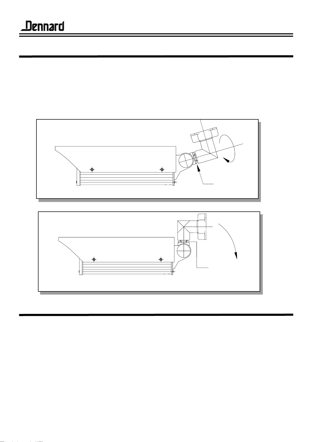
Locking nut
Locking nut
Rotate 180°
The type 508 housing comes packed in the orientation shown in (fig.1)
To bring the 508 into operational service follow the following procedure.
1. Using the spanner (supplied) loosen the locking nut.
2. Rotate the extruded bracket arm and cast base through 180°
3. Retighten the locking nut, ensuring the extruded bracket arm is in the
desired position. (fig2)
The 508 housing is now ready to mount. (Refer to mounting Instructions
Section)
Fig.1
Fig.2
Method
Unpacking
508 operation manual Sheet. 1
Page 3
A. 1 x Type 508 housing
B. 1 x Type 508 Handbook
C. 1 x 3mm A/F Allen Key
D. 1 x 4mm A/F Allen Key
E. 1 x 5mm A/F Allen Key
F. 1 x Spanner
G. 1 x Insulating Pad
H. 1 x Screw Insulator
I. 1 x 1/4” UNC x 3/8” Hex Hd. screw
J. 1 x M6 Plain Washer
K. 1 x M20 Cable Gland
List of contents
508 operation manual Sheet. 2
Before installation please remove the components from the packaging and
check that all items listed below have been supplied.
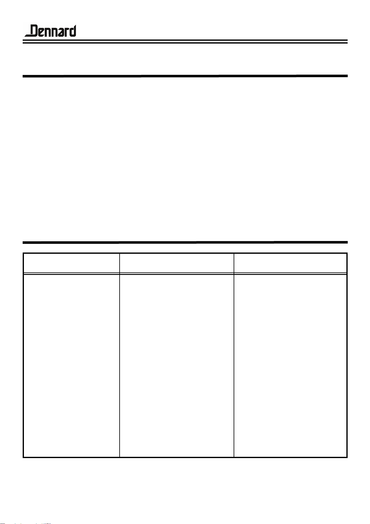
Component Spares
Heater - 240V
Heater - 110V
Heater - 24V
Heater - 12V
Thermostat
Window
Front Gasket
Rear Gasket
Fuse 1 Amp
Sealing Plug
Cable Gland
Gland Nut
Gland Washer
C590
C622
C623
C624
H12a
H146
A84
A85
C15
Z20
H66
H67
H66a
1
1
1
1
1
1
1
1
1
3
1
1
1
Description Ref.No. Quantity
Page 4
508 operation manual Sheet. 3
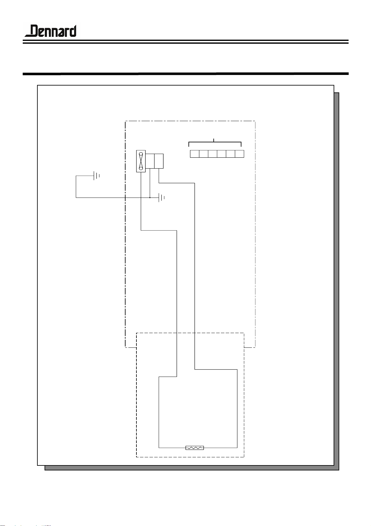
Circuit Diagram
Unit fitted with a 20 x 5mm 1 Amp fuse as standard. It is the
customers responsibility to change the fuse to suit their own
application.
Cover
Earth
TB1
PLATFORM
FTB
FS1
L
E
N
Chassis
Earth
PCB1
PTC
Spare
Page 5

508 operation manual Sheet. 4
To gain access to the 508 housing the following procedure should be followed.
1. Remove the 6 off M5 x 20 soc. hd. screws from the back plate, using
the 4mm A/F long series ball allen key, these screws are held captive for
convenience.
2. Slide the body & sunsheild along the camera platform until it
becomes engaged on the hook.
3. Let the body & sunsheild hang from the hook. With the body hanging
from the hook any maintenance/ inspection of the camera and wiring
can be acheived in situ.
Replacing the body is the reverse procedure.
To remove the Body and sunsheild from the platform completely,
unscrew the 2 off M3 nuts from the suspension bracket whilst the body
is in the hanging position.
Operation
1.
2.
3.
Body
Suspension
Bracket
Platform
Hook
Body
Suspension
Bracket
Hook
Platform
View on Arrow ‘A’
Platform
Hook
Camera Platform
locates in the middle
slots only
Arrow
‘A
’
Body
Page 6

508 operation manual Sheet. 5
Mounting Instructions
1.(2 x M6 x40 Soc. Cap hd screws)
4 x M6 x 16 Soc. Hd. Screws
Arrow ‘A’
View on arrow ‘A’
M20 Cable Gland
Wall
mounted configuration
3.
Ceiling
mounted configuration
2 x M6 Grub
Screws
Housing
body &
sunsheild
180°
Remove 4 x M6 x 16 Soc. Hd. screws from rear bracket and rotate cast
base until desired position of M20 cable gland is acheived. Replace M6
screws and tighten firmly.
to convert the housing from wall mounted to ceiling mounted orientation.
Remove 2 off fixings (item1), rotate bracket arm (item2) through 180° and
refit item 1. Loosen locking nut (item 3) & position the housing to the
desired orientation and re-lock.
For additional security 2 x M6 grub screws are provided. To gain access to
these grub screws, gently prise out the two plastic stop plugs. Then using
the 3mm A/F ball allen key (supplied) either one or both of the grub
screws can be tightened with the housing. in the desired orientation. To
re-orientate the hsg. at any time these grub screws must be loosened first.
Page 7

2050 coax operation manual Sheet. 6
Outline Dimensions
Specifications
Weight
Pan Movement
Tilt Movement
Heater Power
Heater Voltage
Weatherproofing Standard
4.0kg
+/- 90°
- 90°
9 Watts
240V
24V
110V
12V
BS.EN.60529 IP66
508 Camera Platform Outline
260 useable internal length
551
Poly-
carbonate
Window
10mm
Thick
Hidden Cable Bracket (Wall Mounted Orientation)
(-90° tilt down) (+/-90° Pan)
Customer
Cable Run
Locking
Nuts
91
175
Fused Mains Terminal Block and 6 way terminal block
Hidden Cable Bracket (Ceiling Mounted Orientation)
(-90° tilt down) (+/-90° Pan)
222
146
84 Max
+/-90° Pan
A
4 off mounting
holes Ø7.5
equi-spaced
on a 101.6
508 Housing Outline
One 3 Way Fused T.B.
One 6 Way T.B.
1 Slot Ø8.0
91
182
260 Useable Internal Length
332
PTC Heater
SURFACE AT
ALL TIMES
WARNING HOT
SERIAL NO.
Page 8

508 operation manual Sheet. 7
Customer Electrical Connections
6.
7.
9.
8.
1.
10.
4.
3.
2.
5.
1.
2.
3.
4.
5.
6.
7.
8.
9.
10.
Platform
Gasket
Housing Back
Plate
423 Bracket
Assembly
Cable Run
Locking Nut
Rubber
Diaphragm
Housing Wiring Layout
Arrow ‘B’
Components
Page 9

508 operation manual Sheet. 8
View on Rear T.B.’s
Arrow ‘B’
Customer Electrical Connections
Ref.
L
E
N
1
2
3
4
5
6
Function
Line
Earth
Neutral
Spare
Spare
Spare
Spare
Spare
Spare
1 to 6
L
E
N
From
Heater
 Loading...