

Page 1
Industrial Communications Worldwide
Correctional Institute Ringdown Telephone
Model CIR-41
Installation & Operation
P005722 Rev. B 060501 3/8/2007 9:00 AM
Ph: 403.258.3100 \ email:info@guardiantelecom.com \ www.guardiantelecom.com
7552 - 10th Ave. N.E. Calgary Alberta, Canada T2E 8W1
Page 2

Guardian Telecom Inc.
Installation and Operation
Model CIR-41
Table of Contents
Package Contents..........................................................................................2
Overview.........................................................................................................3
Features .........................................................................................................3
Installing the CIR-41.......................................................................................6
Operating the CIR-41 .....................................................................................6
Engineering Specifications.............................................................................7
Warranty.........................................................................................................8
Disclaimer.......................................................................................................8
Warning..........................................................................................................8
Service Telephone Number............................................................................8
Feedback........................................................................................................8
Guardian Product Return................................................................................9
Table of Figures
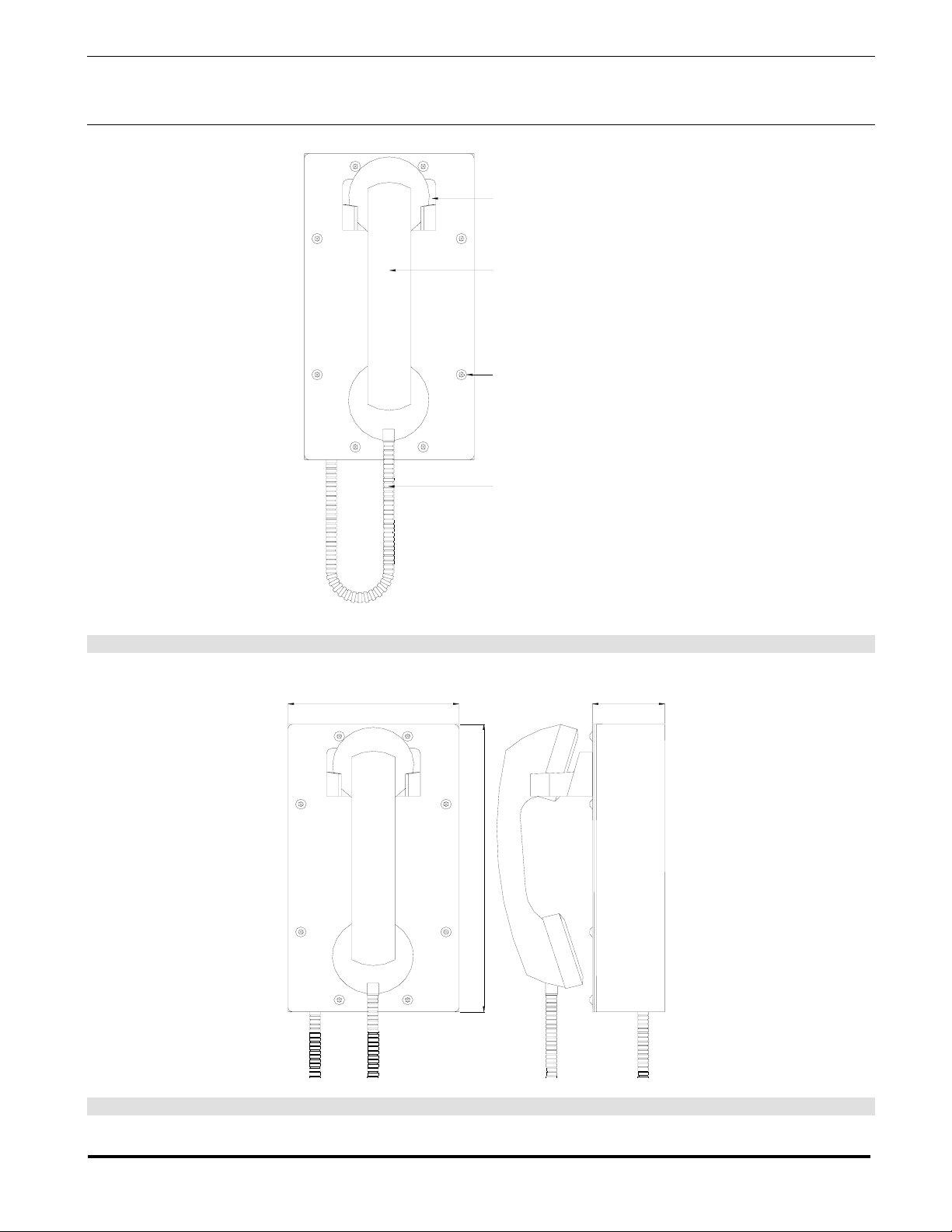
Figure 1 - Features.........................................................................................4
Figure 2 - Dimensions ....................................................................................4
Figure 3 - Mounting ........................................................................................5
Figure 4 - Electrical Connections....................................................................5
Package Contents
(1) CIR-41 Telephone
(1) Installation & Operation Manual
(1) Tamper Resistant Screw Driver Bit
Page 2
Page 3

Guardian Telecom Inc.
Installation and Operation
Model CIR-41
Overview
CIR-41 Correctional Institute Ringdown Telephone
The CIR-41 is a rugged, ringdown telephone designed to provide safe and reliable communication in
locations prone to abuse and vandalism. Calls may be received on this telephone however outgoing
calls will only be connected to a single number – if the PABX is programmed to perform this function
or if a Guardian AD-10 Autodialer is installed and programmed.
Features
Enclosure and Faceplate
• 16 AWG steel, zinc dichromate plated and powder coated, faceplate
secured with vandal resistant screws.
Handset
• high impact ABS with locked on caps
Hook Switch
• magnetic reed hook switch, no moving parts
Surge Arrestor and Fuse
• prevents damage to the electronic circuits in the event of a high
voltage spike on the telephone line
Noise Reducing Microphone
• aids in clarity of transmission in noisy areas
Armoured Handset Cord
• withstands vandalism and severe use
Hearing-Aid Compatible
• compatible with inductively coupled hearing-aid devices
Page 3
Page 4
Guardian Telecom Inc.
Installation and Operation
Model CIR-41
SEALED MAGNETIC REED
HOOK SWITCH
HIGH IMPACT ABS HANDSET C/W
HEARING AID COMPATIBLE EARPIECE
AND GLUED ENDCAPS
TAMPER RESISTANT SCREWS
ARMOURED CORD
Figure 1 - Features
5.0" [127mm] 2.1" [54mm ]
9.0" [229mm]
Figure 2 - Dimensions
Page 4
Page 5

Guardian Telecom Inc.
Installation and Operation
Model CIR-41
1.7" [42mm]1.7" [42mm]
1.5" [38mm]
1.7" [42mm]1.7" [42mm]
1.5" [38mm]
Figure 3 - Mounting
CONNECT TO FACEPLATE
HARNESS
FUSE
FROM RINGER
CONNECT TO HOUSING
HARNESS
FROM REED SWITCH
FROM HANDSET
RJ11 CONNECTOR
TIP AND RING
GROUND
Figure 4 - Electrical Connections
Page 5
Page 6

Guardian Telecom Inc.
Installation and Operation
Model CIR-41
Installing the CIR-41
• Follow all appropriate electrical codes and use only approved electrical
fittings for the installation.
• Choose a wall location that is free of obstructions and permits space for
cable or conduit runs.
• Ensure mounting can support 4lbs (1.8kg) and any additional load to which
the telephone may be subjected.
• Ensure that none of the electrical connection circuits are live.
• Bring Tip, Ring and Ground wiring to the location where the wiring access
opening in the back of the CIR-41 will be when the telephone is installed.
• Remove the eight (8) cover screws from the front of the unit and carefully
remove the front cover assembly. NOTE that the handset and all
electronics are attached to the front plate. The front cover may be
separated from the back box by disconnecting the harness plug.
• Use the enclosure as a template to locate and drill holes for #8 or M4
mounting screws or other suitable attachments.
• Feed Tip, Ring and Ground wiring through the wiring access opening and
secure the unit to the wall.
• Attach individual wires from the exchange (Tip/Ring/Ground) to the terminal
strip (Tip & Ring are not polarity sensitive), or plug the RJ11 connector into
the socket if this termination method was chosen. Even if an RJ11
connector is used an approved earth ground must still be provided to the
ground connection on the terminal strip.
• Ensure all connections are tight, then replace and secure the cover.
• Connect the telephone into the system.
• Test the unit by calling to and from another unit on the exchange.
See: Figure 2 Dimensions
Tip: The CIR-41 may be
wired directly to the
terminal block or an
RJ11 connector may be
used.
Tip: Use the driver bit
provided to remove the
tamper resistant screws.
See: Figure 3 Mounting.
See: Figure 4 - Electrical
Connections
Note: an approved earth
ground must be
connected to the ground
position on the terminal
strip regardless of Tip
and Ring wiring method.
Operating the CIR-41
• The CIR-41 Autodialer phone is designed for receiving calls and for
connecting to a single number – if the PABX is programmed to perform this
function. Calling out is automatic simply by removing the handset from the
cradle.
Page 6
Page 7

Guardian Telecom Inc.
Installation and Operation
Model CIR-41
Engineering Specifications
ELECTRICAL PERFORMANCE
AUDIBLE RANGE FREQUENCY RESPONSE 300 – 3400 HZ
TRANSMIT OBJECTIVE LOUDNESS RATING (TOLR) -38 +/- 3 dB
RECEIVE OBJECTIVE LOUDNESS RATING (ROLR) TYPICAL 50 +/- 3 dB
SIDE TONE OBJECTIVE LOUDNESS RATING (SOLR) TYPICAL 11 +/- 3 dB
RINGER OUTPUT 75 dB MAX
FCC RINGER EQUIVALENCE 0.8B
SET IMPEDANCE 600 OHMS NOMINAL
MAXIMUM LOOP 15,000 FT (4,600 M) OF 22 AWG COPPER
ELECTRICAL REQUIREMENTS
RINGER SENSITIVITY 40 – 100 V, 16 – 25 HZ
LINE VOLTAGE 24 – 56 VDC
LOOP CURRENT 20 - 120 MA
CONNECTION METHOD TERMINAL STRIP OR RJ11 CONNECTOR
ENVIRONMENTAL
TEMPERATURE -40
HUMIDITY 0 TO 95% RH
DUSTPROOF FULL ENCLOSURE GASKET
MECHANICAL
O
TO +60
O
C (-40
O
TO +140
O
F)
HOOK SWITCH (CRADLE SWITCH) LIFE >1 000 000 OPERATIONS
BODY AND FACEPLATE CONSTRUCTION 16 GAUGE STEEL, ZINC DICHROMATE PLATED
AND POWDER COATED
DIMENSIONS (H X W X D) 9 X 5 X 5.2 INCHES (229 X 127 X 132 MM)
NET WEIGHT 5 LBS (2.3 KG)
HANDSET MATERIAL HIGH IMPACT ABS
MICROPHONE NOISE REDUCING ELECTRET
OPTIONAL MICROPHONE NOISE CANCELING DYNAMIC
RECEIVER HEARING AID COMPATIBLE
STANDARD MOUNTING VERTICAL WALL
WIRING ACCESS REAR OPENING 1.5 X 1.5 INCHES ( 38 X 38 MM)
HARDWARE MATERIAL STAINLESS STEEL
Page 7
Page 8

Guardian Telecom Inc.
Installation and Operation
Model CIR-41
Warranty
Guardian Telecom warrants your product to be free of defects in material and workmanship for a period
of one year. Guardian Telecom will repair or replace any defective unit that is under warranty
This warranty is null and void if any non-authorized modifications have been made to this product, or if
it has been subjected to misuse, neglect, or accident. This warranty covers bench repairs only; such
repairs must be made at Guardian Telecom or an authorized service depot. Guardian Telecom is not
responsible for costs incurred for on-site service calls, freight, or brokerage.
A return authorization must be obtained prior to warranty claims or repairs.
Disclaimer
The products covered by this manual are designed for use in Industrial Environments and/or Hazardous
Locations. Due to the range of possible applications for these instruments the manufacturer will not be
responsible for damages or losses of any kind suffered as a result of the use of this product, including
consequential damages.
Warning
This device may be opened and reassembled by qualified personnel only, for the purposes of installing
the product and replacing fuses, following the instructions in the product manual.
High voltages may be present in this product when connected to telephone wiring.
Service Telephone Number
1-800-363-8010
Guardian Telecom provides a customer service telephone number which is toll-free within North
America. If you need assistance when installing or operating this product, please call the toll-free
telephone number between regular business hours (8:00AM-5:00PM), Mountain Standard Time. If you
are calling outside of regular business hours, please leave a detailed message, and a member of
Guardian Telecom’s Service Department will return your call as soon as possible. If your product
requires service, Guardian personnel will supply you with an RMA (return materials authorization)
number over the telephone or through our web site product return page. This number must be included
with your return address and the name of the person to contact.
Guardian Telecom Inc.
7552 10th Ave NE
Calgary, Alberta, Canada T2E 8W1
Toll-free 1-800-363-8010
Ph. (403) 258-3100
Fax. (403) 253-4967
www.guardiantelecom.com
E-mail: mailto:sales@guardiantelecom.com
Feedback
Guardian Telecom continually strives to make reliable, durable, and easy to use products. If you, as an
installer or user of our equipment, have any suggestions for improvements to this or any of our products
or documents, including this manual, we would appreciate hearing from you.
Page 8
Page 9

Guardian Telecom Inc.
Installation and Operation
Model CIR-41
Guardian Product Return
Guardian products have been quality tested and are in full working order when shipped from
the factory, given the rugged nature of these products shipping is not expected to damage a
unit. In the unlikely event of a malfunction, Guardian follows the three step procedure below.
Step I - On-Site Correction
• The most common source of difficulties with a new product is improper installation in one of
two ways: incorrect wiring connections or connection to an incorrect power sour ce.
• Product wiring needs to be properly connected to the on-site wiring. Correct wi ring
instructions are shown in the user manual included with the product.
• Connecting a telephone to a standard power source, rather than tip & ring, will blow the
telephone’s internal, user-replaceable fuse. In the event of fuse burn-out, disconnect the
telephone from the power source, replace the fuse, and reconnect following the wiring
diagrams provided with the product.
Step II - Return Materials Authorization (RMA)
• When a product has been installed following user manual instructions, and the unit fails to
operate, the user must contact Guardian Telecom to obtain authorization to return the
product. This can be done by completing a RMA form online at
www.guardiantelecom.com, or by calling the service telephone number given in this
manual.
• After providing information on the product, the owner and the nature of the problem,
Guardian will issue a RMA number, to be shown on documentation returned with the
product.
• In addition to the RMA number, shipping documents should include name, address and
telephone number of the owner along with contact information for the person responsible
for the repair and/or the user who identified the malfunction.
• (Where a product is being returned for repair from outside of Canada, customs
documentation must show the product’s serial number, date of export [date of purchase],
and a notation that the equipment is: “Canadian goods returning.”)
Step III - Factory Authorized Service
• Once received, each product is carefully inspected and tested. If the product is under
warranty, repairs are completed and the product returned to the owner, generally within
five working days of receipt by the factory.
• A product that has been subjected to misuse, neglect or accident or is beyond the warranty
period will be evaluated. The service department will provide the owner’s representative
with a repair cost estimate. Once approved, repairs are completed and the product
returned, generally within five working days.
Page 9
Page 10

Guardian Telecom Inc.
Installation and Operation
Model CIR-41
Notes:
Model No.
Part No.
Serial No.
Date of Purchase
Page 10
Page 11

Page 12

Guardian Telecom Inc.
Installation and Operation
Model CIR-41
Guardian Telecom Inc.
7552 10th Ave NE
Calgary, Alberta, Canada T2E 8W1
Toll-free 1-800-363-8010
Ph. (403) 258-3100
Fax. (403) 253-4967
www.guardiantelecom.com
E-mail: mailto:sales@guardiantelecom.com
(Click to open message box)
Industrial Communications Worldwide
© Guardian Telecom Inc. 2006
Page 12
 Loading...