

Page 1
Owner’s
Manual
• SAFETY
• ASSEMBLY
ULTRA SOURCE
Portable Generator
• OPERATION
• TROUBLESHOOTING
• ELECTRICAL DATA
• PARTS
• WARRANTY
AUTHORIZED DEALER SUPPORT:
COMMERCIAL • INDUSTRIAL • RESIDENTIAL
MODEL: 004583-0
17,500 Watt Portable Generator
and 60 amp manual transfer switch
with built-in load center
1-800-333-1322
Page 2

Table of Contents
Residential Portable Generator System
Introduction .....................................................................................1
Read this manual Thoroughly .......................................................1
Safety Rules .................................................................................... 2
Standards Index....................................................................3
Section 1 – General Information ...................................................4
1.1 Unpacking...............................................................................4
1.1.1 Accessory Box .........................................................4
1.2 Assembly ................................................................................4
1.2.1 Assembling the Wheel Kit ........................................4
1.2.2 Assembling the Handle ............................................ 4
1.2.3 Battery Connection .................................................. 5
Section 2 – Operation ....................................................................6
2.1 Know the Generator ...............................................................6
2.2 Cord Sets and Connection Plugs ........................................... 7
2.2.1 120 VAC, 20 Amp, Duplex Receptacle .................... 7
2.2.2 120 VAC, 20 Amp, GFCI Receptacle ....................... 7
2.2.3 120 VAC, 30 Amp Receptacle .................................7
2.2.4 120/240 VAC, 30 Amp, Receptacle ..........................8
2.2.5 12 VDC, 10 Amp Receptacle ...................................8
2.2.6 120/240 VAC, 50 Amp, Receptacle ..........................8
2.3 How to Use the Generator .....................................................8
2.3.1 Grounding the Generator .........................................8
2.3.2 Connecting Electrical Loads ....................................9
2.4 Don’t Overload the Generator ................................................9
2.5 Wattage Reference Guide ......................................................9
2.6 Before Starting the Generator ..............................................10
2.6.1 Adding Engine Oil .................................................. 10
2.6.2 Adding Gasoline ....................................................10
2.7 To Start the Engine ..............................................................11
2.8 Stopping the Engine .............................................................11
2.9 Automatic Idle Control .......................................................... 12
2.10 Cold Weather Operation/De-Icer ..........................................12
2.11 Low Oil Pressure Shutdown System ....................................12
2.11.1 Initial Start-up.........................................................12
2.11.2 Sensing Low Oil Pressure ..................................... 12
2.11.3 Restarting ..............................................................12
2.12 Charging a Battery ............................................................... 12
Section 3 – Maintenance .............................................................13
3.1 Maintenance Schedule .........................................................13
3.2 Product Specifications ..........................................................13
3.2.1 Generator Specifications........................................13
3.2.2 Engine Specifications ............................................13
3.3 General Recommendations ..................................................14
3.3.1 Generator Maintenance .........................................14
3.3.2 To Clean the Generator .........................................14
3.3.3 Engine Maintenance ..............................................14
3.3.4 Checking Oil Level ................................................. 14
3.3.5 Changing the Oil and Oil Filter ..............................14
3.3.6 Replacing the Spark Plug ......................................15
3.4 Service Air Cleaner ..............................................................15
3.5 Clean Spark Arrestor Screen ............................................... 15
3.6 Adjusting Valve Clearance ....................................................16
3.7 General ...............................................................................16
3.8 Long Term Storage ...............................................................17
3.9 Other Storage Tips ...............................................................17
Section 4 – Troubleshooting ........................................................18
4.1 Troubleshooting Guide .........................................................18
Section 5 – Installation for Manual Transfer Switch .................19
5.1 Kit Includes ...........................................................................19
5.2 Tools Required .....................................................................19
5.3 Items that Must be Purchased .............................................19
5.4 Transfer Switch Installation ...................................................19
Section 6 – Operation Of Generator With
Manual Transfer Switch ........................................... 23
6.1 Using the Portable Generator and Transfer Switch .............. 23
6.2 Transfer to Generator Power Source
when Utility Power Fails .......................................................24
6.3 Transfer Back to Utility Power Source .................................. 24
Section 7 – Notes ......................................................................... 25
Section 8 – Electrical Data ..........................................................27
Section 9 – Exploded Views and Parts Lists .............................32
Section 10 – Warranty ..................................................................44
Page 3

INTRODUCTION
Thank you for purchasing this model by Generac Power Systems, Inc.
This model is a compact, high performance, air-cooled, engine driven
generator designed to supply electrical power to operate electrical
loads where no utility power is available or in place of utility due to a
power outage.
READ THIS MANUAL THOROUGHLY
If any portion of this manual is not understood, contact the nearest
Authorized Dealer for starting, operating and servicing procedures.
Throughout this publication, and on tags and decals affixed to the
generator, DANGER, WARNING, CAUTION and NOTE blocks are
used to alert personnel to special instructions about a particular
operation that may be hazardous if performed incorrectly or carelessly.
Observe them carefully. Their definitions are as follows:
DANGER
After this heading, read instructions that, if not strictly
complied with, will result in serious personal injury, including
death and/or property damage.
After this heading, read instructions that, if not strictly
complied with, may result in serious personal injury and/or
property damage.
After this heading, read instructions that, if not strictly
complied with, could result in damage to equipment and/or
property.
NOTE:
After this heading, read explanatory statements that require
special emphasis.
These safety warnings cannot eliminate the hazards that they indicate.
Common sense and strict compliance with the special instructions
while performing the service are essential to preventing accidents.
Four commonly used safety symbols accompany the DANGER,
WARNING and CAUTION blocks. The type of information each
indicates is as follows:
This symbol points out important safety information that,
if not followed, could endanger personal safety and/or
property of others.
This symbol points out potential explosion
hazard.
This symbol points out potential fire hazard.
This symbol points out potential electrical shock hazard.
We also strongly recommend instructing other users to properly
start and operate the unit. This prepares them if they need to
operate the equipment in an emergency.
Always disconnect spark plug wires and place the wires
where they cannot contact the spark plugs to prevent
accidental starting when setting up, transporting, adjusting
or making repairs to the generator.
•
The generator produces dangerously high voltage that can cause
extremely hazardous electrical shock. Avoid contact with bare
wires, terminals, etc. Never permit any unqualified person to
operate or service the generator.
•
Never handle any kind of electrical cord or device while standing
in water, while barefoot or while hands or feet are wet. Dangerous
electrical shock will result.
•
The National Electric Code requires the frame and external
electrically conductive parts of the generator be properly connected
to an approved earth ground. Local electrical codes may also
require proper grounding of the generator. Consult with a local
electrician for grounding requirements in the area.
•
Use a ground fault circuit interrupter in any damp or highly
conductive area (such as metal decking or steel work).
•
Do not use worn, bare, frayed or otherwise damaged electrical
cord sets with the generator.
•
Operate generator only on level surfaces and where it will not be
exposed to excessive moisture, dirt, dust or corrosive vapors.
•
Gasoline is highly FLAMMABLE and its vapors are EXPLOSIVE.
Do not permit smoking, open flames, sparks or heat in the vicinity
while handling gasoline. Avoid spilling gasoline on a hot engine.
Comply with all laws regulating storage and handling of gasoline.
•
Never add fuel while unit is running.
Do not overfill the fuel tank. Always allow room for fuel
expansion. If tank is over-filled, fuel can overflow onto a
hot engine and cause FIRE or an EXPLOSION.
Never store generator with fuel in tank where gasoline vapors
•
might reach an open flame, spark or pilot light (as on a furnace,
water heater or clothes dryer). FIRE or EXPLOSION may result.
Generator exhaust gases contain DEADLY carbon monoxide gas.
•
This dangerous gas, if breathed in sufficient concentrations, can
cause unconsciousness or even death. Operate this equipment
only in the open air where adequate ventilation is available.
Allow at least two (2) feet of clearance on all sides of generator or
•
damage could be done to the unit. Never operate the unit inside
any room or enclosure where the free flow of cooling air into and
out of the unit might be obstructed. Review the “Cold Weather
Operation” section.
DANGER
NEVER operate the generator indoors, in an attached
garage or near an open window.
The operator is responsible for proper and safe use of the
equipment. We strongly recommend that the operator read this
manual and thoroughly understand all instructions before using
the equipment.
1
Page 4

IMPORTANT SAFETY INSTRUCTIONS
Portable Generator System
SAVE THESE INSTRUCTIONS – The manufacturer suggests that these rules for safe operation be copied and posted near the unit's
installation site. Safety should be stressed to all operators and potential operators of this equipment.
Never start or stop the unit with electrical loads connected to
•
receptacles AND with connected devices turned ON. Start
the engine and let it stabilize before connecting electrical
loads. Disconnect all electrical loads before shutting down the
generator.
Do not insert objects through unit's cooling slots.
•
Never operate generator: indoors or in any enclosed compartment;
•
in rain; if connected electrical devices overheat; if electrical output
is lost; if engine or generator sparks; if flames or smoke are
observed while unit is running; if unit vibrates excessively.
NOTE:
This generator is equipped with a spark arrestor muffler. The
spark arrestor must be maintained in effective working order by
the owner/ operator. In the State of California, a spark arrestor is
required by law (Section 4442 of the California Public Resources
Code). Other states may have similar laws. Federal laws apply
on federal lands.
Study these SAFETY RULES carefully before installing, operating or
servicing this equipment. Become familiar with this manual and with
the unit. The generator can operate safely, efficiently and reliably only
if it is properly installed, operated and maintained. Many accidents
are caused by failing to follow simple and fundamental rules or
precautions.
The engine exhaust from this product
contains chemicals known to the state
of California to cause cancer, birth
defects or other reproductive harm.
This product contains or emits chemicals
known to the state of California to cause
cancer, birth defects or other reproductive harm.
The manufacturer cannot anticipate every possible circumstance that
might involve a hazard. The warnings in this manual, and on tags and
decals affixed to the unit are, therefore, not all inclusive. If using a
procedure, work method or operating technique that the manufacturer
does not specifically recommend, ensure that it is safe for others. Also
make sure the procedure, work method or operating technique utilized
does not render the generator unsafe.
WARNING!
WARNING!
Despite the safe design of this generator, operating this
equipment imprudently, neglecting its maintenance or
being careless can cause possible injury or death. Permit
only responsible and capable persons to operate or
maintain this equipment.
Potentially lethal voltages are generated by these
machines. Ensure all steps are taken to render the
machine safe before attempting to work on the generator.
Parts of the generator are rotating and/or hot during
operation. Exercise care near running generators.
GENERAL HAZARDS
Never operate in an enclosed area or indoors.
•
For safety reasons, the manufacturer recommends that the
•
maintenance of this equipment is carried out by an Authorized
Dealer.
The engine exhaust fumes contain carbon monoxide, which
•
can be DEADLY. This dangerous gas, if breathed in sufficient
concentrations, can cause unconsciousness or even death. This
exhaust system must be properly maintained. Do nothing that
might render the exhaust system unsafe or in noncompliance with
any local codes and/or standards.
Keep hands, feet, clothing, etc., away from drive belts, fans, and
•
other moving or hot parts. Never remove any drive belt or fan guard
while the unit is operating.
Adequate, unobstructed flow of cooling and ventilating air is critical
•
to correct generator operation. Do not alter the installation or
permit even partial blockage of ventilation provisions, as this can
seriously affect safe operation of the generator. The generator
MUST be operated outdoors.
When working on this equipment, remain alert at all times. Never
•
work on the equipment when physically or mentally fatigued.
Inspect the generator regularly, and contact the nearest Authorized
•
Dealer for parts needing repair or replacement.
Before performing any maintenance on the generator, disconnect
•
its battery cables to prevent accidental start up. Disconnect the
cable from the battery post indicated by a NEGATIVE, NEG or (–)
first. Reconnect that cable last.
Never use the generator or any of its parts as a step. Stepping on
•
the unit can stress and break parts, and may result in dangerous
operating conditions from leaking exhaust gases, fuel leakage, oil
leakage, etc.
DANGER
2
Page 5

IMPORTANT SAFETY INSTRUCTIONS
Portable Generator System
ELECTRICAL HAZARDS
•
All generators covered by this manual produce dangerous electrical
voltages and can cause fatal electrical shock. Utility power delivers
extremely high and dangerous voltages as does the generator
when it is in operation. Avoid contact with bare wires, terminals,
connections, etc., while the unit is running. Ensure all appropriate
covers, guards and barriers are in place before operating the
generator. If work must be done around an operating unit, stand on
an insulated, dry surface to reduce shock hazard.
•
Do not handle any kind of electrical device while standing in water,
while barefoot, or while hands or feet are wet. DANGEROUS
ELECTRICAL SHOCK MAY RESULT.
•
The National Electrical Code (NEC) requires the frame and external
electrically conductive parts of the generator to be connected to an
approved earth ground. Local electrical codes also may require
proper grounding of the generator electrical system.
•
In case of accident caused by electric shock, immediately shut
down the source of electrical power. If this is not possible,
attempt to free the victim from the live conductor. AVOID DIRECT
CONTACT WITH THE VICTIM. Use a non-conducting implement,
such as a rope or board, to free the victim from the live conductor.
If the victim is unconscious, apply first aid and get immediate
medical help.
•
Never wear jewelry when working on this equipment. Jewelry can
conduct electricity resulting in electric shock, or may get caught in
moving components causing injury.
FIRE HAZARDS
For fire safety, the generator must be operated and maintained
•
properly. Operation must always comply with applicable codes,
standards, laws and regulations. Adhere strictly to local,
state and national electrical and building codes. Comply with
regulations the Occupational Safety and Health Administration
(OSHA) has established. Also, ensure that the generator is
operated in accordance with the manufacturer’s instructions and
recommendations. Do not alter the construction of the generator
or change controls which might create an unsafe operating
condition.
Keep a fire extinguisher near the generator at all times. Extinguishers
•
rated “ABC” by the National Fire Protection Association are
appropriate for use on the standby electric system. Keep the
extinguisher properly charged and be familiar with its use. If there
are any questions pertaining to fire extinguishers, consult the local
fire department.
EXPLOSION HAZARDS
Do not smoke around the generator. Wipe up any fuel or oil spills
•
immediately. Ensure that no combustible materials are left on or
near the generator, as FIRE or EXPLOSION may result. Keep the
area surrounding the generator clean and free from debris.
Gasoline is extremely EXPLOSIVE.
•
STANDARDS INDEX
In the absence of pertinent standards, codes, regulations and laws,
the published information listed below may be used as a guideline
for operation of this equipment. Always reference the latest revision
available for the standards listed.
1. NFPA No. 70, NFPA HANDBOOK OF NATIONAL ELECTRIC
CODE.
2. Article X, NATIONAL BUILDING CODE, available from the
American Insurance Association, 85 John Street, New York, N.Y.
10038.
3. AGRICULTURAL WIRING HANDBOOK, available from the Food
and Energy Council, 909 University Avenue, Columbia, MO
65201.
4. ASAE EP-3634, INSTALLATION AND MAINTENANCE OF
FARM STANDBY ELECTRICAL SYSTEMS, available from the
American Society of Agricultural Engineers, 2950 Niles Road, St.
Joseph, MI 49085.
5. NFPA No. 30, FLAMMABLE AND COMBUSTIBLE LIQUIDS
CODE.
3
Page 6
Section 1 – General Information
Portable Generator System
1.1 UNPACKING
Set the palleted carton on a rigid flat surface.
•
Remove staples along bottom of carton that fasten carton to pallet.
•
Open carton from top.
Remove all packaging material.
•
Remove separate accessory box.
•
Lift carton off the generator.
•
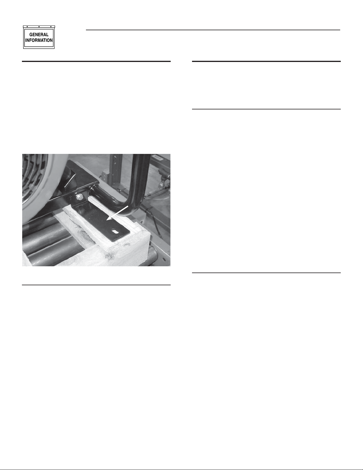
Remove generator from shipping pallet by removing bolts through
•
the shipping brackets (Figure 1).
Figure 1 - Bracket Removal
Shipping
Bracket (x4)
1.2 ASSEMBLY
The generator requires some assembly prior to using it. If problems
arise when assembling the generator, please call the Generator
Helpline at 1-800-333-1322.
1.2.1 ASSEMBLING THE WHEEL KIT
The wheel kit is designed to greatly improve the portability of the
generator. A socket wrench with a 9/16” socket, a 1/2” socket, a
1/2” wrench and a pair of pliers are the tools that will be needed for
assembly of the wheel kit.
NOTE:
The wheel kit is not intended for over-the-road use.
Refer to Figure 2 and install the wheel kit as follows:
•
Place the generator on a hard flat surface.
•
Stand at the engine end of the unit and gently tilt the generator
•
forward, high enough to place wooden blocks beneath the cradle.
This will allow space to install the wheel assemblies.
Attach an axle bracket assembly with attached sleeve to either side
•
of the frame. Ensure the sleeve faces outward.
Slide the axle through the sleeves on the axle brackets.
•
Slide one wheel with flat washer to the outside and a spacer to the
•
inside onto each end of the axle. Make sure the air inflation valve
on the wheel is facing outward.
Insert retaining pins and using pliers, bend out the ends to prevent
•
the pins from falling out of the axle. Remove the wooden blocks.
1.1.1 ACCESSORY BOX
Check all contents. If any parts are missing or damaged locate an
authorized dealer at 1-800-333-1322.
Contents include:
Wheel Axle • Bolt-on tubular handle
•
2 – Washers • 2 – Pneumatic Wheels
•
2 – Wheel Spacers • 2 – Axle Bracket Assemblies
•
2 – Cotter Pins • Bolt-on Foot
•
Battery Charge Cable • Spark Plug Wrench
•
Air Filter • Oil Filter
•
Pre-cleaner • 2 – Quarts Oil
•
26 Wire Nuts • 6 – Carriage Bolts, Washers, Nuts
•
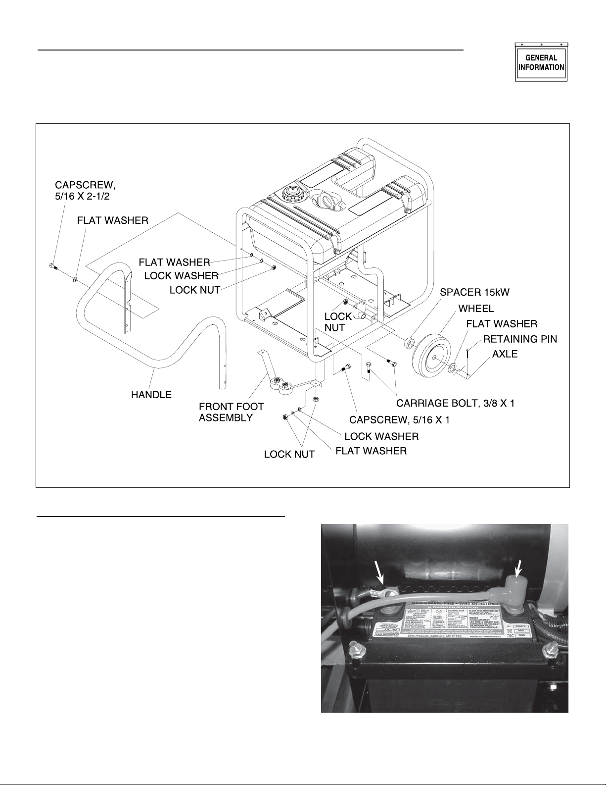
1.2.2 ASSEMBLING THE HANDLE
Attach the handle by aligning one side of the handle on the cradle,
•
then spread the handle around the cradle and let it spring into
place. Secure the handle to the frame using the 5/16’ hex head
bolts provided. Check each fastener to ensure that it is secure.
Using the handle, lift the unit high enough to place wooden blocks
•
under the unit. Attach the front support foot to the underside of the
cradle using the 3/8” carriage bolts provided.
Remove the shipping brackets from the cradle, if you have not
•
already done so.
4
Page 7
Section 1 - General Information
Portable Generator System
Figure 2 - Handle Assembly
1.2.3 BATTERY CONNECTION
The battery shipped with the generator has been provided fully
•
charged. Caution must be taken when connecting the battery.
NOTE:
A battery may lose some of it’s charge when not in use for
prolonged periods of time.
Cut the tie wrap cable holding the RED and BLACK battery cables
•
to the stator.
Connect the RED battery cable to the battery Positive terminal (+).
•
After making sure that the connection is tight, slip the rubber boot
over the terminal connection.
Connect the BLACK battery cable to the battery Negative terminal
•
(–). Make sure the connection is tight.
Double check all connections to ensure they are in the correct
•
location and secure. See Figure 3.
Figure 3 - Battery Connections
Negative
Cable
Positive
Cable
5
Page 8
Section 2 – Operation
Portable Generator System
2.1 KNOW THE GENERATOR
Read the Owner’s Manual and Safety Rules before operating this
generator.
Compare the generator to Figures 4 through 6 to become familiarized
with the locations of various controls and adjustments. Save this
manual for future reference.
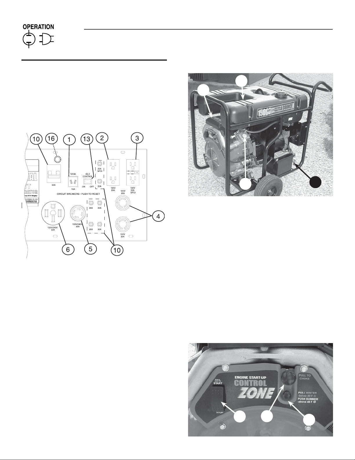
Figure 4 - Control Panel
1. 12 Volt DC, 10 Amp Receptacle – This receptacle allows the
capability to recharge a 12 volt DC storage battery with provided
battery charge cables.
2. 120 Volt AC, 20 Amp, Duplex Receptacle – Supplies electrical
power for the operation of 120 Volt AC, 20 Amp, single-phase, 60
Hz electrical lighting, appliance, tool and motor loads.
3. 120 Volt AC, 20A Duplex GFCI Receptacle – Supplies ground
fault protected electrical power for operation of 120 volt AC 20
amp, single-phase, 60 Hz electric lighting, appliances, tools and
motor loads.
4. 120 Volt AC, 30 Amp Locking Receptacle – Supplies electrical
power for the operation of 120 Volt AC, 30 Amp, single-phase, 60
Hz electrical lighting, appliance, tool and motor loads.
5. 120/240 Volt AC, 30 Amp Locking Receptacle – Supplies
electrical power for the operation of 120 and/or 240 Volt AC, 30
Amp, single-phase, 60 Hz, electrical lighting, appliance, tool and
motor loads.
6. 120/240 Volt AC, 50 Amp Receptacle (Located on underside
of control panel)– Supplies electrical power for the operation of
120/240 Volt AC, 50 Amp, single-phase, 60 Hz, welder or motor
loads.
7. Air Cleaner – Filters intake air as it is drawn into the engine.
8. Choke Knob – Used when starting a cold engine.
6
Figure 5 - Generator Controls
11
7
15
9. Winter/Summer Valve – See “Cold Weather Operation/De-icer”
section.
10. Circuit Breakers (AC) – Each receptacle is provided with a
push-to-reset circuit breaker to protect the generator against
electrical overload. (50 amp uses toggle reset)
11. Fuel Tank – Tank holds 16 U.S. gallons of fuel.
12. Grounding Lug – Ground the generator to an approved earth
ground here. See "Grounding the Generator" for details.
13. Idle Control Switch – The idle control runs the engine at normal
(high) speeds when there is an electrical load present and runs
the engine at idle (low) speeds when a load is not present.
14. Start/Run/Stop Switch – Controls the operation of the
generator.
15. Oil Fill – Use this point to add oil to engine.
16. Fuse - 10 Amp (Located at rear of control panel) – Protects
the DC control circuit from overload. If this fuse element has
melted open the engine will not be able to crank and start.
Figure 6 - Engine Control Panel
14
8
12
9
Page 9
Section 2 – Operation
Portable Generator System
2.2 CORD SETS AND CONNECTION
PLUGS
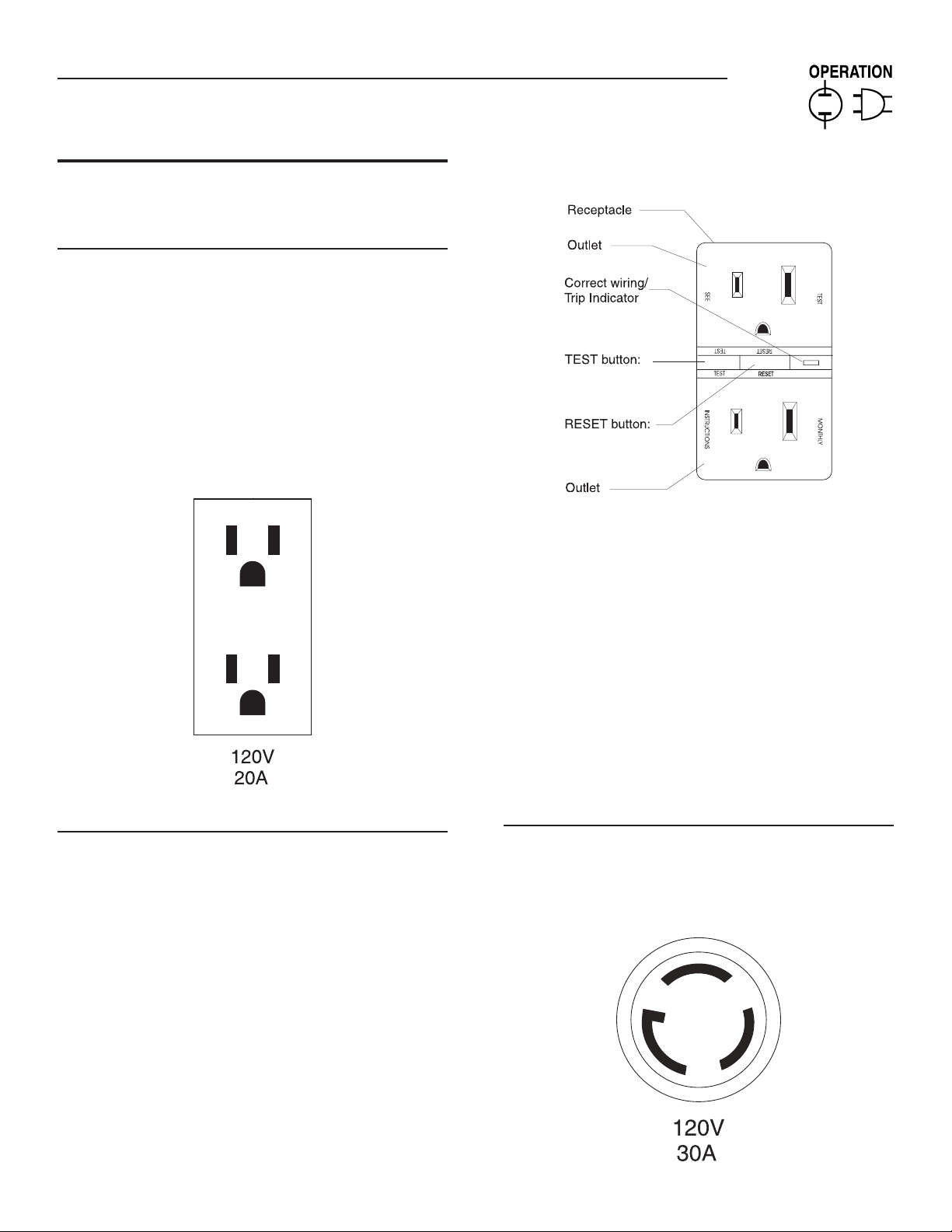
2.2.1 120 VAC, 20 AMP, DUPLEX RECEPTACLE
This is a 120 Volt outlet protected against overload by a 20 Amp
push-to-reset circuit breaker (Figure 7). Use each socket to power
120 Volt AC, single phase, 60 Hz electrical loads requiring up to a
combined 2400 watts (2.4 kW) or 20 Amps of current. Use only high
quality, well-insulated, 3-wire grounded cord sets rated for 125 Volts
at 20 Amps (or greater).
Keep extension cords as short as possible, preferably less than 15
feet long, to prevent voltage drop and possible overheating of wires.
Figure 7 - 120 Volt AC, 20 Amp, Duplex
Receptacle
Figure 8 - 120 VAC, 20 Amp GFCI Receptacle
Testing the GFCI: Test the GFCI outlet every month as follows:
Plug a test lamp into the receptacle.
•
Start the generator, the test lamp should be on.
•
Press the “Test” button located on the front of the receptacle to
•
trip the device.
This should stop the flow of electricity making the lamp shut off.
•
The yellow trip indicator should now be on.
To restore the flow of electricity, press the “Reset” button on the
•
front of the receptacle. If the GFCI does not perform in this manner,
do not use the receptacle. Contact a local service dealer.
This outlet is protected against overload by a 20A push-to-reset
•
circuit breaker. Use the outlet to power 120V AC, single-phase,
60 Hz, electrical loads requiring up to a combined 2400 watts (2.4
kW) or 20 amps of current.
2.2.2 120 VAC, 20 AMP, GFCI RECEPTACLE
This unit is equipped with a ground fault circuit interrupter (GFCI). This
device meets applicable federal, state and local codes (Figure 8).
A GFCI receptacle is different from conventional receptacles. In the
event of a ground fault, a GFCI will trip and quickly stop the flow of
electricity to prevent serious injury.
Definition: Instead of following its normal safe path, electricity passes
through a persons body to reach the ground. For example, a defective
appliance can cause a ground fault.
A GFCI receptacle does NOT protect against circuit overloads, short
circuits, or shocks. For example, electric shock can still occur if a
person touches charged electrical wires while standing on a nonconducting surface, such as a wood floor.
2.2.3 120 VAC, 30 AMP RECEPTACLE
Use a NEMA L5-30 plug with this receptacle. Connect a 3-wire cord
set rated for 125 Volts AC at 30 Amps (or greater) to the plug (Figure
9).
Figure 9 - 120 VAC, 30 Amp Receptacle
7
Page 10
Section 2 – Operation
Portable Generator System
Use this receptacle to operate 120 Volt AC, 60 Hz, single phase loads
requiring up to 3600 watts (3.6 kW) of power at 30 Amps. The outlet
is protected by a 30 Amp push-to-reset circuit breaker.
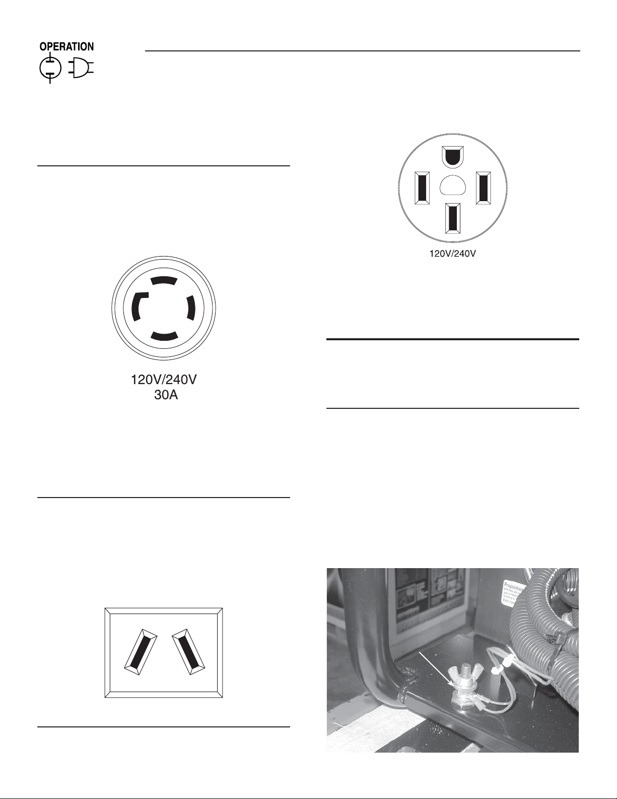
2.2.4 120/240 VAC, 30 AMP RECEPTACLE
Use a NEMA L14-30 plug with this receptacle. Connect a suitable 4wire grounded cord set to the plug and to the desired load. The cord
set should be rated for 250 Volts AC at 30 Amps (or greater) (Figure
10).
Figure 10 - 120/240 VAC, 30 Amp Receptacle
Use this receptacle to operate 120 Volt AC, 60 Hz, single phase loads
requiring up to 3600 watts (3.6 kW) of power at 30 Amps or 240 Volt
AC, 60 Hz, single phase loads requiring up to 7200 watts (7.2 kW)
of power at 30 Amps. The outlet is protected by two 30 Amp push-toreset circuit breakers.
2.2.5 12 VOLT DC, 10 AMP RECEPTACLE
This receptacle permits recharging a 12 Volt automotive or utility style
storage battery with the battery charge cables provided (Figure 11).
This receptacle can not recharge 6 Volt batteries and can not be
used to crank an engine having a discharged battery. See the section
"Charging a Battery" before attempting to recharge a battery.
Figure 12 - 120/240 VAC, 50 Amp Receptacle
50 A
Use this receptacle to operate 120/240 Volt AC, 60 Hz electrical loads
requiring up to 12,000 watts (12.0 kW) of power. This receptacle is
protected by a 50 Amp 2-pole circuit breaker.
2.3 HOW TO USE THE GENERATOR
If there are any problems operating the generator, please call the
generator helpline at 1-800-333-1322.
2.3.1 GROUNDING THE GENERATOR
The National Electrical Code requires that the frame and external
electrically conductive parts of this generator be properly
connected to an approved earth ground (Figure 13). Local
electrical codes may also require proper grounding of the unit. For
that purpose, generally, connecting a No. 10 AWG (American Wire
Gauge) stranded copper wire to the grounding wing nut and to an
earth-driven copper or brass grounding rod (electrode) provides
adequate protection against electrical shock. However, local codes
may vary widely. Consult with a local electrician for grounding
requirements in the area.
Figure 13 - Grounding the Generator
Figure 11 - 12 Volt DC, 10 Amp Receptacle
2.2.6 120/240 VAC, 50 AMP RECEPTACLE
Use a NEMA 14-50 plug with this receptacle. Connect a 4-wire cord
set rated for 250 Volts AC at 50 Amps to the plug (Figure 12).
8
Generator Ground Lug
Page 11

Section 2 – Operation
Portable Generator System
Proper grounding of the generator will help prevent electrical
shock in the event of a ground fault condition in the generator or in
connected electrical devices. Proper grounding also helps dissipate
static electricity, which often builds up in ungrounded devices.
2.3.2 CONNECTING ELECTRICAL LOADS
DO NOT connect 240 Volt loads to 120 Volt receptacles. DO NOT
connect 3-phase loads to the generator. DO NOT connect 50 Hz loads
to the generator.
Let engine stabilize and warm up for a few minutes after starting.
•
Plug in and turn on the desired 120 or 240 Volt AC, single phase,
•
60 Hz electrical loads.
Add up the rated watts (or amps) of all loads to be connected
•
at one time. This total should not be greater than (a) the rated
wattage/amperage capacity of the generator or (b) circuit breaker
rating of the receptacle supplying the power. See "Don't Overload
the Generator" below.
2.4 DON’T OVERLOAD THE GENERATOR
Overloading a generator in excess of its rated wattage capacity can
result in damage to the generator and to connected electrical devices.
Observe the following to prevent overloading the unit:
Add up the total wattage of all electrical devices to be connected
•
at one time. This total should NOT be greater than the generator's
wattage capacity.
The rated wattage of lights can be taken from light bulbs. The rated
•
wattage of tools, appliances and motors can usually be found on a
data plate or decal affixed to the device.
If the appliance, tool or motor does not give wattage, multiply volts
•
times ampere rating to determine watts (volts x amps = watts).
Some electric motors, such as induction types, require about three
•
times more watts of power for starting than for running. This surge
of power lasts only a few seconds when starting such motors.
Make sure to allow for high starting wattage when selecting
electrical devices to connect to the generator:
1. Figure the watts needed to start the largest motor.
2. Add to that figure the running watts of all other connected
loads.
The Wattage Reference Guide is provided to assist in determining
how many items the generator can operate at one time.
NOTE:
All figures are approximate. See data plate on appliance for
wattage requirements.
2.5 WATTAGE REFERENCE GUIDE
Device. . . . . . . . . . . . . . . . . . . . . . . . . . . . . . . . . . . . . . . . Running Watts
*Air Conditioner (12,000 Btu) . . . . . . . . . . . . . . . . . . . . . . . . . . . . . . 1700
*Air Conditioner (24,000 Btu) . . . . . . . . . . . . . . . . . . . . . . . . . . . . . . 3800
*Air Conditioner (40,000 Btu) . . . . . . . . . . . . . . . . . . . . . . . . . . . . . . 6000
Battery Charger (20 Amp). . . . . . . . . . . . . . . . . . . . . . . . . . . . . . . . . . 500
Belt Sander (3") . . . . . . . . . . . . . . . . . . . . . . . . . . . . . . . . . . . . . . . . 1000
Chain Saw. . . . . . . . . . . . . . . . . . . . . . . . . . . . . . . . . . . . . . . . . . . . . 1200
Circular Saw (6-1/2"). . . . . . . . . . . . . . . . . . . . . . . . . . . . . . . .800 to 1000
*Clothes Dryer (Electric) . . . . . . . . . . . . . . . . . . . . . . . . . . . . . . . . . 5750
*Clothes Dryer (Gas). . . . . . . . . . . . . . . . . . . . . . . . . . . . . . . . . . . . . . 700
*Clothes Washer . . . . . . . . . . . . . . . . . . . . . . . . . . . . . . . . . . . . . . . . 1150
Coffee Maker. . . . . . . . . . . . . . . . . . . . . . . . . . . . . . . . . . . . . . . . . . . 1750
*Compressor (1 HP) . . . . . . . . . . . . . . . . . . . . . . . . . . . . . . . . . . . . . 2000
*Compressor (3/4 HP). . . . . . . . . . . . . . . . . . . . . . . . . . . . . . . . . . . . 1800
*Compressor (1/2 HP). . . . . . . . . . . . . . . . . . . . . . . . . . . . . . . . . . . . 1400
Curling Iron . . . . . . . . . . . . . . . . . . . . . . . . . . . . . . . . . . . . . . . . . . . . . 700
*Dehumidifier. . . . . . . . . . . . . . . . . . . . . . . . . . . . . . . . . . . . . . . . . . . . 650
Disc Sander (9") . . . . . . . . . . . . . . . . . . . . . . . . . . . . . . . . . . . . . . . . 1200
Edge Trimmer . . . . . . . . . . . . . . . . . . . . . . . . . . . . . . . . . . . . . . . . . . . 500
Electric Blanket . . . . . . . . . . . . . . . . . . . . . . . . . . . . . . . . . . . . . . . . . . 400
Electric Nail Gun . . . . . . . . . . . . . . . . . . . . . . . . . . . . . . . . . . . . . . . . 1200
Electric Range (per element) . . . . . . . . . . . . . . . . . . . . . . . . . . . . . . 1500
Electric Skillet . . . . . . . . . . . . . . . . . . . . . . . . . . . . . . . . . . . . . . . . . . 1250
*Freezer . . . . . . .. . . . . . . . . . . . . . . . . . . . . . . . . . . . . . . . . . . . . . . . ..700
*Furnace Fan (3/5 HP) . . . . . . . . . . . . . . . . . . . . . . . . . . . . . . . . . . . . 875
*Garage Door Opener. . . . . . . . . . . . . . . . . . . . . . . . . . . . . . . .500 to 750
Hair Dryer . . . . . . . . . . . . . . . . . . . . . . . . . . . . . . . . . . . . . . . . . . . . . 1200
Hand Drill . . . . . . . . . . . . . . . . . . . . . . . . . . . . . . . . . . . . . . . .250 to 1100
Hedge Trimmer . . . . . . . . . . . . . . . . . . . . . . . . . . . . . . . . . . . . . . . . . . 450
Impact Wrench . . . . . . . . . . . . . . . . . . . . . . . . . . . . . . . . . . . . . . . . . . 500
Iron . . . . . . . . . . . . . . . . . . . . . . . . . . . . . . . . . . . . . . . . . . . . . . . . . . 1200
*Jet Pump . . . . . . . . . . . . . . . . . . . . . . . . . . . . . . . . . . . . . . . . . . . . . . 800
Lawn Mower . . . . . . . . . . . . . . . . . . . . . . . . . . . . . . . . . . . . . . . . . . . 1200
Light Bulb . . . . . . . . . . . . . . . . . . . . . . . . . . . . . . . . . . . . . . . . . . . . . . 100
Microwave Oven . . . . . . . . . . . . . . . . . . . . . . . . . . . . . . . . . . .700 to 1000
*Milk Cooler. . . . . . . . . . . . . . . . . . . . . . . . . . . . . . . . . . . . . . . . . . . . 1100
Oil Burner on Furnace . . . . . . . . . . . . . . . . . . . . . . . . . . . . . . . . . . . . 300
Oil Fired Space Heater (140,000 Btu) . . . . . . . . . . . . . . . . . . . . . . . . 400
Oil Fired Space Heater (85,000 Btu) . . . . . . . . . . . . . . . . . . . . . . . . . 225
Oil Fired Space Heater (30,000 Btu) . . . . . . . . . . . . . . . . . . . . . . . . . 150
*Paint Sprayer, Airless (1/3 HP) . . . . . . . . . . . . . . . . . . . . . . . . . . . . . 600
Paint Sprayer, Airless (handheld) . . . . . . . . . . . . . . . . . . . . . . . . . . . . 150
Radio. . . . . . . . . . . . . . . . . . . . . . . . . . . . . . . . . . . . . . . . . . . . . .50 to 200
*Refrigerator . . . . . . . . . . . . . . . . . . . . . . . . . . . . . . . . . . . . . . . . . . . . 700
Slow Cooker . . . . . . . . . . . . . . . . . . . . . . . . . . . . . . . . . . . . . . . . . . . . 200
*Submersible Pump (1-1/2 HP). . . . . . . . . . . . . . . . . . . . . . . . . . . . . 2800
*Submersible Pump (1 HP). . . . . . . . . . . . . . . . . . . . . . . . . . . . . . . . 2000
*Submersible Pump (1/2 HP) . . . . . . . . . . . . . . . . . . . . . . . . . . . . . . 1500
*Sump Pump . . . . . . . . . . . . . . . . . . . . . . . . . . . . . . . . . . . . . .800 to 1050
*Table Saw (10") . . . . . . . . . . . . . . . . . . . . . . . . . . . . . . . . . .1750 to 2000
Television . . . . . . . . . . . . . . . . . . . . . . . . . . . . . . . . . . . . . . . . .200 to 500
Toaster . . . . . . . . . . . . . . . . . . . . . . . . . . . . . . . . . . . . . . . . .1000 to 1650
Weed Trimmer. . . . . . . . . . . . . . . . . . . . . . . . . . . . . . . . . . . . . . . . . . . 500
* Allow 3 times the listed watts for starting these devices.
9
Page 12
Sy nt he ti c 5W -2 0, 5W -3 0
SA E 30 ,
1 0W -3 0
Section 2 – Operation
Portable Generator System
2.6 BEFORE STARTING THE GENERATOR
Prior to operating the generator, engine oil and gasoline will need to
be added, as follows:
2.6.1 ADDING ENGINE OIL
NOTE:
When adding oil to the engine crankcase in the future, use only
high quality detergent oil rated with API service classification
SG, SH or SL SAE 30 weight. Use no special additives.
SAE 30
10W-30
Synthetic 5W-20, 5W-30
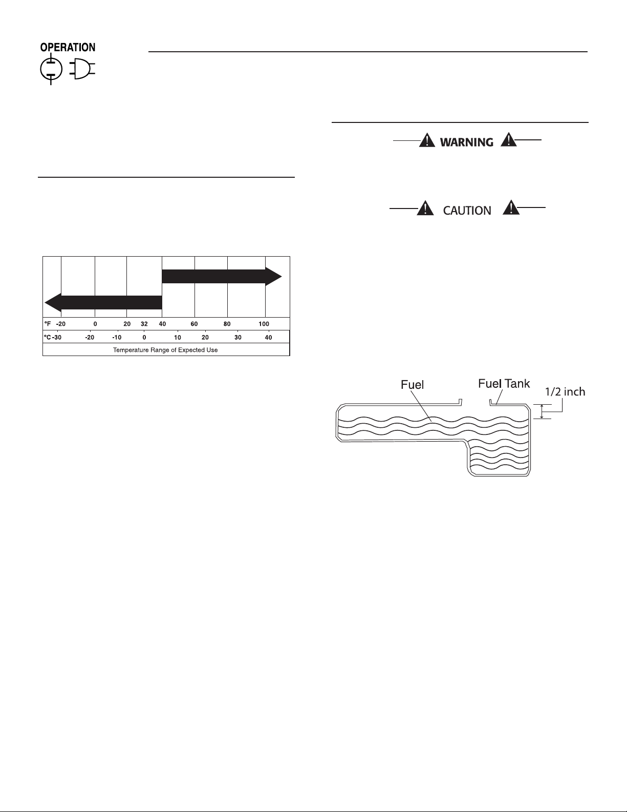
Select the oil’s viscosity grade according to the expected operating
temperature. Do not use SAE 10W-40.
NOTE:
Synthetic oil should only be used after first oil change.
Above 40°F, use SAE 30, or 10W-30.
•
Below 40°F, use synthetic 5W-20 or 5W-30.
•
Although multi-viscosity oils (5W-30, 10W-30, etc.) improve starting
in cold weather, these multi-viscosity oils will result in increased oil
consumption when used above 32°F. Check the engine oil level more
frequently to avoid possible damage from running low on oil.
Place generator on a level surface.
•
Clean area around oil fill and remove oil fill cap and dipstick.
•
Wipe dipstick clean.
•
Slowly fill engine with oil through the oil fill opening until it reaches
•
the full mark on the dipstick. Stop filling occasionally to check oil
level. DO NOT OVERFILL.
Install dipstick. Install oil fill cap and finger tighten securely.
•
Check engine oil level before starting each time thereafter.
•
2.6.2 ADDING GASOLINE
Never fill fuel tank indoors. Never fill fuel tank when engine
is running or hot. DO NOT light a cigarette or smoke when
filling the fuel tank.
Do not overfill the fuel tank. Always leave room for fuel
expansion.
•
Use regular UNLEADED gasoline with the generator engine. Do
not use premium gasoline. Do not mix oil with gasoline.
•
Clean area around fuel fill cap, remove cap.
•
Slowly add unleaded regular gasoline to fuel tank. Be careful not
to overfill. Allow about 1/2" of tank space for fuel expansion, as
shown here (Figure 14).
•
Install fuel cap and wipe up any spilled gasoline.
Figure 14 - Fuel Tank
IMPORTANT: It is important to prevent gum deposits from forming
in fuel system parts such as the carburetor, fuel hose or tank during
storage. Alcohol-blended fuels (called gasohol, ethanol or methanol)
can attract moisture, which leads to separation and formation of acids
during storage. Acidic gas can damage the fuel system of an engine
while in storage. To avoid engine problems, the fuel system should
be emptied before storage of 30 days or longer. See the "Storage"
section. Never use engine or carburetor cleaner products in the fuel
tank as permanent damage may occur.
10
Page 13
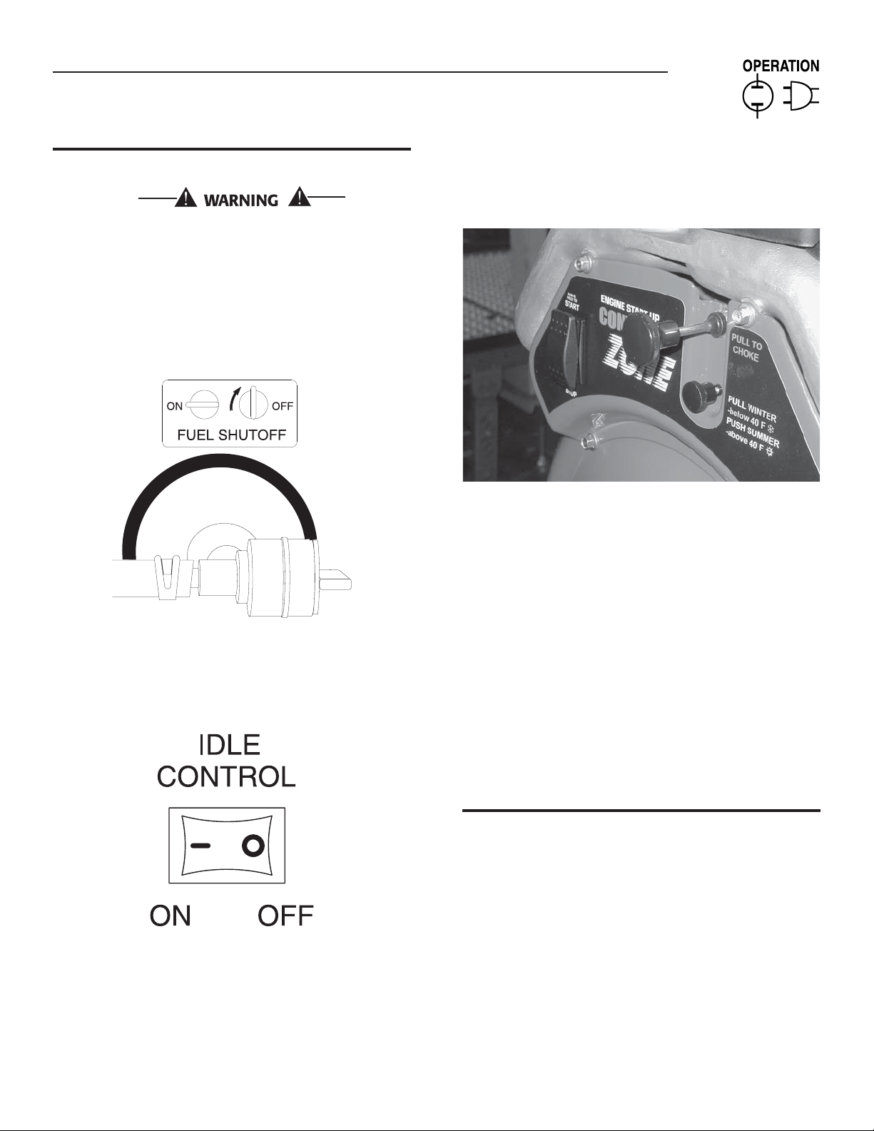
2.7 TO START THE ENGINE
Never start or stop engine with electrical devices plugged
into the receptacles AND devices turned on.
Unplug all electrical loads from the unit's receptacles before
•
starting the engine.
Make sure the unit is in a level position.
•
Open the fuel shut-off valve (Figure 15).
•
Figure 15 - Fuel Shut-off Valve
Section 2 – Operation
Portable Generator System
•
Move engine CHOKE knob outward to “Full Choke” position
(Figure 17).
Figure 17 - Full Choke Position
Locate the Idle Control ON/OFF switch on the control panel and
•
set it to the “OFF” position(Figure 16).
Figure 16 - Idle Control Switch
To start engine, press and hold the Start/Run/Stop switch in the
•
“Start” position. The engine will crank and attempt to start. When
the engine starts, release the switch to the run position.
When the engine starts, move choke knob to “1/2 Choke” position
•
until the engine runs smoothly and then fully in to the “Run” position.
If engine falters, move choke knob back out to “1/2 Choke” position
until the engine runs smoothly and then to “Run” position.
NOTE:
If engine fires, but does not continue to run, move choke lever to
“Full Choke” and repeat starting instructions.
IMPORTANT: Do not overload the generator. Also, do not overload
individual panel receptacles. These outlets are protected against
overload with push-to-reset-type circuit breakers. If amperage rating
of any circuit breaker is exceeded, that breaker opens and electrical
output to that receptacle is lost. Read “Don’t Overload the Generator”
carefully.
2.8 STOPPING THE ENGINE
Shut off all loads, then unplug the electrical loads from generator
•
panel receptacles. Never start or stop the engine with electrical
devices plugged in and turned on.
Turn “Off” the Idle Control switch (if on).
•
Let engine run at no-load for several minutes to stabilize the
•
internal temperatures of engine and generator.
Move Start/Run/Stop switch to “Off” position.
•
Close fuel valve.
•
11
Page 14

Section 2 – Operation
Portable Generator System
2.9 AUTOMATIC IDLE CONTROL
This feature is designed to greatly improve fuel economy. When
this switch is turned “On,” the engine will only run at its normal fast
governed engine speed when electrical load is connected. When
the load is removed, the engine will run at a reduced speed of 2100
RPM. With the switch “Off,” the engine runs at the normal fast engine
speed all the time. Always have the switch OFF when starting and
stopping the engine.
2.10 COLD WEATHER OPERATION/DE-ICER
Under certain weather conditions (temperatures below 40° F (4°
C) and a high dew point), the engine may experience icing of the
carburetor and/or the crankcase breather system. To eliminate this
problem, this generator engine is fitted with a winter/summer valve.
This directs hot air into the carburetor during cold weather operation.
Always make sure the winter/summer valve is in the correct location
relative to the weather conditions.
2.11 LOW OIL PRESSURE SHUTDOWN
SYSTEM
The engine is equipped with a low oil pressure sensor that shuts down
the engine automatically when the oil pressure drops below 10 psi. If
the engine shuts down by itself and the fuel tank has enough gasoline,
check engine oil level.
2.11.1 INITIAL START-UP
A delay built into the low oil shutdown system allows oil pressure to
build during starting. The delay allows the engine to run for about 10
seconds before sensing oil pressure.
2.11.2 SENSING LOW OIL PRESSURE
If the system senses low oil pressure during operation, the engine
shuts down.
2.11.3 RESTARTING
If trying to restart the engine within 10 seconds after it shuts down, the
engine may NOT start. The system needs 5 to 10 seconds to reset.
If the engine is restarted after such a shutdown and the low oil
pressure has not been corrected, the engine will run for about 10
seconds as described above and then stop.
2.12 CHARGING A BATTERY
DANGER
Storage batteries give off explosive hydrogen gas while
recharging. An explosive mixture will remain around the
battery for a long time after it has been charged. The
slightest spark can ignite the hydrogen and cause an
explosion. Such an explosion can shatter the battery and
cause blindness or other serious injury.
DANGER
Do not permit smoking, open flame, sparks or any other
source of heat around a battery. Wear protective goggles,
rubber apron and rubber gloves when working around a
battery. Battery electrolyte fluid is an extremely caustic
sulfuric acid solution that can cause severe burns. If spill
occurs flush area with clear water immediately.
This generator has the capability of recharging a discharged 12 Volt
automotive or utility style storage battery. Do not use the unit to
charge any 6 Volt batteries. Do not use the unit to crank an engine
having a discharged battery.
This battery charger is a pulse type designed to provide a quality
charge current into the battery. The voltage measured at the outlet
should be 8-12 VDC. This is normal and does not indicate a faulty
charging system.
To recharge 12 Volt batteries, proceed as follows:
Check fluid level in all battery cells. If necessary, add ONLY distilled
•
water to cover separators in battery cells. Do not use tap water.
If the battery is equipped with vent caps, make sure they are
•
installed and are tight.
If necessary, clean battery terminals.
•
Connect battery charge cable connector plug to panel receptacle
•
identified by the words "12-VOLT D.C."
Connect battery charge cable clamp with red handle to the positive
•
(+) battery terminal.
Connect battery charge cable clamp with black handle to the
•
negative (-) battery terminal.
Start engine. Let the engine run while battery recharges. Engine
•
idle control switch must be in off position for battery charging.
When battery has charged, shut down engine.
•
NOTE:
Use an automotive hydrometer to test battery state of charge and
condition. Follow the hydrometer manufacturer's instructions
carefully. Generally, a battery is considered to be at 100% state
of charge when specific gravity of its fluid (as measured by
hydrometer) is 1.260 or higher.
12
Page 15

Section 3 — Maintenance
Residential Portable Generator System
3.1 MAINTENANCE SCHEDULE
Follow the calendar intervals. More frequent service is required when operating in adverse conditions noted below.
Operation Maintenance Daily Every Season Every Season Every Season
Check Oil Level
Service Air Pre-Cleaner **
Change Oil and Oil Filter‡ *
Clean Spark Arrestor Screen
Check Valve Clearance ***
Service Air Cleaner **
Replace Spark Plugs
‡ Change oil after first 8 hours of operation then every season.
* Change oil and oil filter every month when operating under heavy load or in high temperatures.
** Clean more often under dirty or dusty operating conditions. Replace air cleaner parts if very dirty.
*** Check valve clearance and adjust if necessary after first 50 hours of operation and every 100 hours thereafter.
3.2 PRODUCT SPECIFICATIONS
3.2.1 GENERATOR SPECIFICATIONS
MODEL GPS 17,500
Model # 004583-0
Rated Max. Power 17.5 kW
Surge Power 26.2 kW
Rated AC Voltage 120/240
Rated Max AC Load
Current @ 240V 72.9 Amps
Current @ 120V 145.8 Amps
Rated Frequency 60 Hz @ 3600 RPM
Phase Single Phase
Rated DC Voltage 12 Volts
Rated Max DC Load
Current @ 12 Volts 10 Amperes
3.2.2 ENGINE SPECIFICATIONS
Rated Horsepower
@ 3600 RPM 33
Displacement 992cc
Spark Plug Type Champion RC14YC or Equivalent
Spark Plug Gap 0.040 inch or (1.01 mm)
Gasoline Capacity 16 U.S. gallons
Oil Type Summer – SAE 30 or 10W-30 Winter – Synthetic 5W-20 or 5W-30
Oil Capacity w/ Filter Change = 1.7 Qts. w/o Filter Change = 1.4 Qts.
Run Time/Fuel 10 Hours / 1.6 gallons per hour
Consumption-1/2 Load
13
Page 16

Section 3 — Maintenance
Portable Generator System
3.3 GENERAL RECOMMENDATIONS
The warranty of the generator does not cover items that have been
subjected to operator abuse or negligence. To receive full value from
the warranty, the operator must maintain the generator as instructed
in this manual.
Some adjustments will need to be made periodically to properly
maintain the generator.
All adjustments in the Maintenance section of this manual should
be made at least once each season. Follow the requirements in the
"Maintenance Schedule".
NOTE:
Once a year replace the spark plug and replace the air filter. A
new spark plug and clean air filter assure proper fuel-air mixture
and help the engine run better and last longer.
3.3.1 GENERATOR MAINTENANCE
Generator maintenance consists of keeping the unit clean and dry.
Operate and store the unit in a clean dry environment where it will not
be exposed to excessive dust, dirt, moisture or any corrosive vapors.
Cooling air slots in the generator must not become clogged with snow,
leaves, or any other foreign material.
Check the cleanliness of the generator frequently and clean when
dust, dirt, oil, moisture or other foreign substances are visible on its
exterior surface.
Never insert any object or tool through the air cooling
slots, even if the engine is not running.
NOTE:
DO NOT use a garden hose to clean generator. Water can enter
the engine fuel system and cause problems. In addition, if water
enters the generator through cooling air slots, some water will
be retained in voids and crevices of the rotor and stator winding
insulation. Water and dirt buildup on the generator internal
windings will eventually decrease the insulation resistance of
these windings.
3.3.2 TO CLEAN THE GENERATOR
Use a damp cloth to wipe exterior surfaces clean.
•
A soft, bristle brush may be used to loosen caked on dirt, oil, etc.
•
A vacuum cleaner may be used to pick up loose dirt and debris.
•
Low pressure air (not to exceed 25 psi) may be used to blow away
•
dirt. Inspect cooling air slots and openings on the generator. These
openings must be kept clean and unobstructed.
3.3.3 ENGINE MAINTENANCE
DANGER
When working on the generator, always disconnect
negative cable from battery. Also disconnect spark plug
wires from spark plug and keep wire away from spark plug.
3.3.4 CHECKING OIL LEVEL
See the “BEFORE STARTING THE GENERATOR” section for
information on checking the oil level. The oil level should be checked
before each use, or at least every eight hours of operation. Keep the
oil level maintained.
3.3.5 CHANGING THE OIL AND OIL FILTER
Change the oil and filter after the first eight hours of operation. Change
the oil every 100 hours thereafter. If running this unit under dirty or
dusty conditions, or in extremely hot weather, change the oil more
often.
NOTE:
Whenever possible, run engine for approximately 5 minutes to
get the engine oil hot. This will aid in draining the oil.
Use the following instructions to change the oil while the engine
is still warm:
Clean area around oil drain hose and plug.
•
Remove oil drain plug from end of hose and oil fill plug to drain oil
•
completely into a suitable container.
When oil has completely drained, install oil drain plug and tighten
•
securely.
Place a suitable container beneath the oil filter and turn
•
filter counterclockwise to remove. Discard according to local
regulations.
Coat gasket of new filter with clean engine oil. Turn filter clockwise
•
until gasket contacts lightly with filter adapter. Then tighten an
additional 3/4 turn.
Fill oil sump with recommended oil. (See “Before Starting the
•
Generator” for oil recommendations).
Wipe up any spilled oil.
•
14
Page 17
Section 3 — Maintenance
Portable Generator System
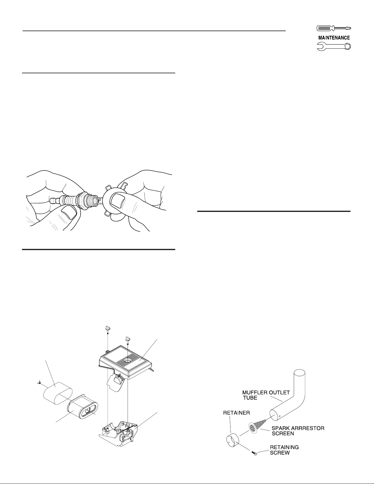
3.3.6 REPLACING THE SPARK PLUG
Use Champion RC14YC spark plug or equivalent. The correct air gap
is 1.01 mm (0.040 in.) (Figure 18). Replace the plug once each year.
This will help the engine start easier and run better.
1. Stop the engine and pull the spark plug wire off of the spark
plug.
2. Clean the area around the spark plug and remove it from the
cylinder head.
3. Set the spark plug's gap to 1.01 mm (0.040 in.). Install the
correctly gapped spark plug into the cylinder head.
Figure 18 - Spark Plug Gap
3.4 SERVICE AIR CLEANER
The engine will not run properly and may be damaged if using a dirty
air cleaner. Clean or replace the air cleaner paper filter once a year
(Figure 19). Clean or replace more often if operating under dusty
conditions. Clean foam pre-cleaner every month or more often under
dusty conditions.
Figure 19 - Air Cleaner
Cover
To clean or replace foam pre-cleaner:
Remove air cleaner cover, then foam pre-filter.
•
Wash pre-cleaner in soapy water. Squeeze pre-filter dry in clean
•
cloth (DO NOT TWIST).
Clean air cleaner cover before re-installing it.
•
To clean or replace paper air filter:
Remove air cleaner cover; then remove foam pre-filter (service if
•
necessary) and remove paper filter.
Clean paper filter by tapping it gently on a solid surface. If the
•
filter is too dirty, replace it with a new one. Dispose of the old filter
properly.
Clean air cleaner cover then slip pre-cleaner over filter. Next insert
•
new paper filter into the base of the air cleaner. Re-install air
cleaner cover.
NOTE:
To order a new air filter, please contact the nearest authorized
service center at 1-800-333-1322.
3.5 CLEAN SPARK ARRESTOR SCREEN
The engine exhaust muffler has a spark arrestor screen. Inspect and
clean the screen at least once each year (Figure 20). If unit is used
regularly, inspect and clean more often.
NOTE:
If using the generator on any forest-covered, brush-covered
or grass-covered unimproved land, it must equipped with a
spark arrestor. The spark arrestor must be maintained in good
condition by the owner/operator.
Clean and inspect the spark arrestor as follows:
Remove the screen retaining bracket by removing the screw.
•
Slide the spark arrestor screen out from the tail pipe.
•
Inspect screen and replace if torn, perforated or otherwise
•
damaged. DO NOT USE a defective screen. If screen is not
damaged, clean it with commercial solvent.
Replace the screen and the retaining bracket.
•
Pre-Cleaner
Filter
Figure 20 - Spark Arrestor
Base
15
Page 18
Section 3 — Maintenance
Portable Generator System
3.6 ADJUSTING VALVE CLEARANCE
After the first 50 hours of operation, check the valve clearance in
the engine and adjust if necessary.
Important: If feeling uncomfortable about doing this procedure or the
proper tools are not available, please take the generator to the nearest
service center to have the valve clearance adjusted. This is a very
important step to insure longest life for the engine.
To check valve clearance:
Make sure the engine is at room temperature (60° - 80° F).
•
Make sure that the spark plug wire is removed from the spark plug
•
and out of the way.
Remove the four screws attaching the valve cover.
•
Make sure the piston is at Top Dead Center (TDC) of its
•
compression stroke (both valves closed). To get the piston at
TDC, remove the intake screen at the front of the engine to gain
access to the flywheel nut. Use a large socket and socket wrench
to rotate the nut and hence the engine in a clockwise direction
while watching the piston through the spark plug hole. The piston
should move up and down. The piston is at TDC when it is up as
high as it can go.
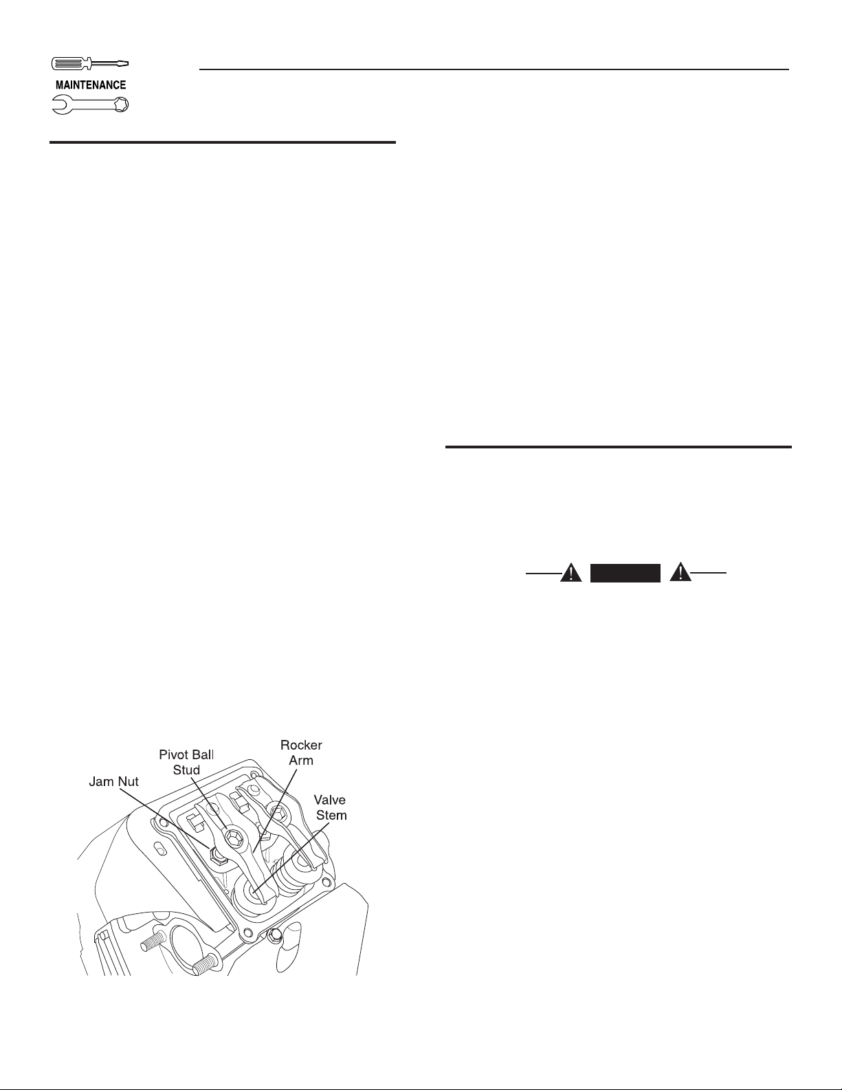
Insert a 0.002 - 0.004 inch (0.05 - 0.1mm) feeler gauge between
•
the rocker arm and valve stem. Correct clearance is when a slight
drag is felt when sliding the gauge back and forth. If the clearance
is either excessively loose or tight the rocker arms will need
adjusting.
To adjust valve clearance:
Loosen the rocker jam nut (Figure 21). Use an 10mm allen wrench
•
to turn the pivot ball stud while checking clearance between
the rocker arm and the valve stem with a feeler gauge. Correct
clearance is 0.002-0.004 inch (0.05-0.1 mm).
NOTE:
The rocker arm jam nut must be held in place as the pivot ball
stud is turned.
When valve clearance is correct, hold the pivot ball stud in place with
the allen wrench and tighten the rocker arm jam nut. Tighten the jam
nut to 174 in/lbs. torque. After tightening the jam nut, recheck valve
clearance to make sure it did not change.
•
Install new valve cover gasket.
•
Re-attach the valve cover.
NOTE:
Start all four screws before tightening or it will not be possible
to get all the screws in place. Make sure the valve cover gasket
is in place.
•
Re-attach the spark plug wire to the spark plug.
•
Repeat the process for the other cylinder.
3.7 GENERAL
The generator should be started at least once every seven days
and be allowed to run at least 30 minutes. If this cannot be done
and the unit must be stored for more than 30 days, use the following
information as a guide to prepare it for storage.
DANGER
NEVER store engine with fuel in tank indoors or in
enclosed, poorly ventilated areas where fumes may reach
an open flame, spark or pilot light as on a furnace, water
heater, clothes dryer or other gas appliance.
Figure 21 - Valve Clearance Adjustment
16
Page 19

Section 3 — Maintenance
Portable Generator System
3.8 LONG TERM STORAGE
It is important to prevent gum deposits from forming in essential fuel
system parts such as the carburetor, fuel hose or tank during storage.
Also, experience indicates that alcohol-blended fuels (called gasohol,
ethanol or methanol) can attract moisture, which leads to separation
and formation of acids during storage. Acidic gas can damage the fuel
system of an engine while in storage.
To avoid engine problems, the fuel system should be emptied before
storage of 30 days or longer, as follows:
Remove all gasoline from the fuel tank.
•
DANGER
Drain fuel into approved container outdoors, away from
open flame. Be sure engine is cool. Do not smoke.
Start and run engine until engine stops from lack of fuel.
•
While engine is still warm, drain oil from crankcase. Refill with
•
recommended grade.
Remove spark plugs and pour about 1/2 ounce (15 ml) of engine
•
oil into the cylinders. Cover spark plug hole with rag. Press the
“Start” button and allow engine to crank for 2 seconds. Then press
the “Stop” button.
3.9 OTHER STORAGE TIPS
Do not store gasoline from one season to another.
•
Replace the gasoline can if it starts to rust. Rust and/or dirt in the
•
gasoline will cause problems with the carburetor and fuel system.
If possible, store the unit indoors and cover it to give protection
•
from dust and dirt. BE SURE TO EMPTY THE FUEL TANK.
If it is not practical to empty the fuel tank and the unit is to be stored
•
for some time, use a commercially available fuel stabilizer added to
the gasoline to increase the life of the gasoline.
Cover the unit with a suitable protective cover that does not retain
•
moisture.
DANGER
NEVER cover the generator while engine and exhaust area
are warm.
Avoid spray from spark plug holes when cranking engine.
Install and tighten spark plugs. Do not connect spark plug wires.
•
Clean the generator outer surfaces. Check that cooling air slots and
•
openings on generator are open and unobstructed.
Store the unit in a clean, dry place.
•
17
Page 20

Section 4 — Troubleshooting
Portable Generator System
4.1 TROUBLESHOOTING GUIDE
PROBLEM CAUSE CORRECTION
Engine is running, but no AC
output is available.
1. Circuit breaker is open.
2. Poor connection or defective cord set.
3. Connected device is bad.
4. Fault in generator.
1. Reset circuit breaker.
2. Check and repair.
3. Connect another device that is in good condition.
4. Contact Authorized Service Facility.
Engine runs good but
bogs down when loads are
connected.
Engine will not crank.
Engine will not start; or
starts and runs rough.
Engine shuts down during
operation.
1. Short circuit in a connected load.
2. Generator is overloaded.
3. Engine speed is too slow.
4. Shorted generator circuit.
1. 10 amp fuse at rear of generator control panel
has melted open.
2. Battery weak or dead.
1. Dirty air cleaner.
2. Out of gasoline.
3. Stale gasoline.
4. Spark plug wire not connected to spark plug.
5. Bad spark plug.
6. Water in gasoline.
7. Overchoking.
8. Low oil level.
9. Excessive rich fuel mixture.
10. Intake valve stuck open or closed.
11. Engine has lost compression.
1. Out of gasoline.
2. Low oil level.
3. Fault in engine.
1. Disconnect shorted electrical load.
2. See “Don’t Overload the Generator” .
3. Contact Authorized Service Facility.
4. Contact Authorized Service Facility.
1. Replace fuse with only an identical 10-amp
replacement fuse.
2. Recharge or replace battery.
1. Clean or replace air cleaner.
2. Fill fuel tank.
3. Drain fuel tank and fill with fresh fuel.
4. Connect wire to spark plug.
5. Replace spark plug.
6. Drain fuel tank; fill with fresh fuel.
7. Put choke knob to No Choke position.
8. Fill crankcase to proper level.
9. Contact Authorized Service Facility.
10. Contact Authorized Service Facility.
11. Contact Authorized Service Facility.
1. Fill fuel tank.
2. Fill crankcase to proper level.
3. Contact Authorized Service Facility.
Engine lacks power.
Engine “hunts” or falters.
No Battery Charge DC
output.
18
1. Load is too high.
2. Dirty air filter.
3. Engine needs to be serviced.
1. Choke is opened too soon.
2. Carburetor is running too rich or too lean.
1. Battery posts are corroded.
2. Battery cable is bad.
3. Battery is defective.
4. Receptacle is bad.
1. See “Don’t Overload the Generator”.
2. Replace air filter.
3. Contact Authorized Service Facility.
1. Move choke to halfway position until engine runs
smoothly.
2. Contact Authorized Service Facility.
1. Clean battery posts.
2. Replace cable.
3. Check battery condition; replace if defective.
4. Contact Authorized Service Facility.
Page 21
Section 5 — Installation for Manual Transfer Switch
Portable Generator System
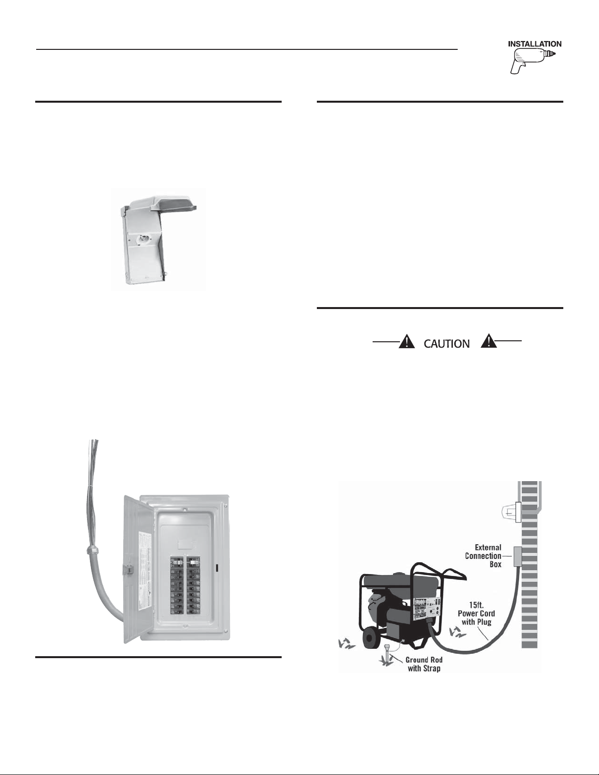
5.1 KIT INCLUDES
1. Power Inlet Box (Figure 22)
Pre-wired with the 50 amp male receptacle, this box is located
outside the home where the generator will be operated.
Figure 22 - Power Inlet Box
2. Pre-wired Manual Transfer Switch and Emergency Load
Center with 16 Circuits (Figure 23)
Installed within 1 foot of the home’s main distribution panel. This
transfer switch will provide smooth and safe transition between
utility and generator power. Eliminates the need to run extension
cords to every item requiring back up power.
3. 2’ Pre-wired Conduit for Easy Connection to the Home’s
Main Distribution Panel (Figure 23)
26 UL listed wire nuts (not shown)
Figure 23 - Power Inlet Box
5.3 ITEMS THAT MUST BE PURCHASED
60 AMP double pole circuit breaker (must be the same type as in
•
your main electrical distribution panel)
Ground rod (8 foot) with grounding strap (No. 10 AWG stranded
•
copper)
Padlock (To lock external connection box after installation is
•
complete)
Silicone caulk
•
Fasteners - to mount transfer switch, connection box and plug
•
house/cord hanger
Intermediate wiring* from Manual Transfer Switch to the Power
•
Inlet Box
*Individual wires in conduit or wiring in a jacketed cable must be sized
for 50 Amp service and of construction approved by the National
Electric Code and other applicable local codes.
5.4 TRANSFER SWITCH INSTALLATION
THESE INSTRUCTIONS ARE TO SERVE AS A GUIDE ONLY!
ANY ELECTRICAL WORK PERFORMED MUST MEET NFPA
70-NEC AND ANY LOCAL CODES THAT APPLY.
1. Plan the location of the generator (must be on flat, level ground).
Figure 24 shows the portable generator placed outside the home
and connected to the weather protective external box. The ground
rod and ground strap show a suggested location only. When fully
installed the ground rod will not protrude above ground level.
5.2 TOOLS REQUIRED
Drill, drill bits, hole saw (type and length will be determined by the
materials you will be drilling and cutting), open-end wrenches or
adjustable wrenches, socket wrenches or nut drivers, standard and
Phillips screwdrivers, sledge hammer, level, pencil, channel-lock
pliers, wire cutters/strippers and safety goggles.
Figure 24 - Generator Location
Generator should be placed as far away from
house as power cord will allow. It is understood
that the cord should not be pulled tight and it
will lay along the ground between the external
connection box and generator panel.
NOTE:
Do not place the generator directly under a window, near an
entrance way or near any intake vents. Always follow local codes
for safe and proper location.
19
Page 22

Section 5 — Installation for Manual Transfer Switch
Portable Generator System
Select an area outside of your home about 10 feet away where you
can easily transport the portable generator to and from. Keep in mind
that the generator must have free air flow for proper operation and to
ensure there is no possibility for exhaust gases to build up.
2. Drive an 8-foot grounding rod into the ground to grade (so that
no part is exposed above ground).
3. Determine where the user supplied conduit will pass through the
house from inside to outside. When you are certain you have
clearance on each side of the wall, drill a small pilot hole through
the wall to mark the location. With hole saw, drill hole through the
sheathing and siding (Figures 25 & 26).
Figure 25 - Drill Hole Through Wall
1-3/4”
Diameter Hole
Figure 27 - Feed Conduit Through Wall
Silicone
Caulk
6. Remove the threaded lock nut from the conduit coupling (Figure
28).
Figure 28 - Remove Lock Nut
Figure 26 - Drill Hole Through Siding
1-3/4”
Diameter Hole
4. Measure the lengths of wire and conduit needed to reach the
Manual Transfer Switch. Allow extra length to clear the joists/
studs. While adhering to all local electrical codes, route the
customer supplied conduit and wiring along ceiling/floor joists
and wall studs to the location where the conduit will pass through
the wall to the exterior of the house.
5. From the inside of the house, feed the end of the customer
supplied conduit through the wall to outside (Figure 27).
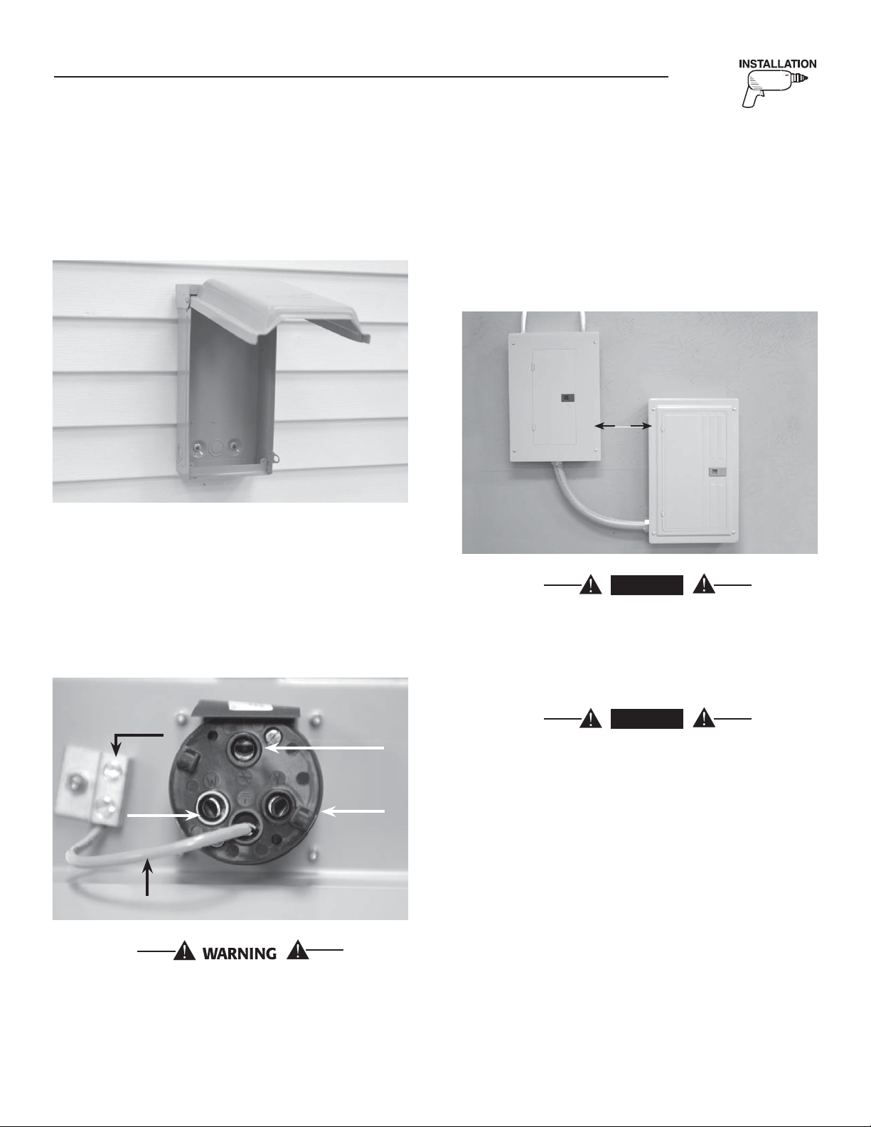
7a. Lift cover of the power inlet box and remove the internal cover
plate screws and internal cover plate (Figure 29). Remove the
knock out in the lower center of the box. From the rear of the
connection box, feed wires into box. Slip the lock nut over wires
and tighten securely onto conduit coupling.
Figure 29 - Prepare Box for Connections
Knockout
20
Page 23
Section 5 — Installation for Manual Transfer Switch
Portable Generator System
7b. Using appropriate fasteners, mount power inlet box over pre-
drilled hole to fully conceal the hole (Figure 30). Seal around the
hole and conduit with insulating material and/or silicone caulk
from both outside and inside of house.
Figure 30 - Mount Box
8. Connect the black, red, and white wires to the same color coded
lugs on the back of the receptacle (Figure 31). Failure to match
wires may result in damage to generator and house wiring. Strip
wire insulation back 1/2” and torque lug screws to 25 in/lbs. The
green wire is to be stripped back 1/2”, inserted into the ground
lug and torque lug screw to 25 in/lbs. Reinstall internal cover
plate and screw. Close and lock cover.
Figure 31 - Connect Wires
9. Mount manual transfer switch with built-in emergency load
center within one foot of main distribution panel (Figure 32). The
manual transfer switch should be located to the right of the main
distribution panel. Hold transfer switch against the mounting
surface. Level the transfer switch and mark the mounting holes.
Drill the appropriate size pilot holes. Mount the manual transfer
switch to mounting surface with appropriate fasteners.
Figure 32 - Mount Manual Transfer Switch
1 ft
DANGER
Although you may choose to perform electrical
connections yourself, the manufacturer recommends that a
licensed electrician or individual with complete knowledge
of electricity perform the procedures in sections 10a and
10b.
Green
White
Existing Wire
The power inlet box must be locked to ensure safety and to
discourage tampering.
Red
Black
DANGER
Switch service main circuit breaker to “off” or open
position prior to removal of cover or removal of any
wiring of the main electrical distribution panel. The wires
connected to the service main circuit breaker remain live
or “hot”. Avoid contact with these wires and the service
main circuit breaker connection lugs.
9a. The 2 foot conduit that is pre-wired into the manual transfer
switch is not fastened to the side of the enclosure when shipped.
To secure the conduit to the manual switch enclosure proceed
as follows. Remove the cover panel of the manual transfer switch
with emergency load center. Insert the 2 foot conduit into the
knockout and tighten the lock nut securely on the inside of the
enclosure.
21
Page 24
Section 5 — Installation for Manual Transfer Switch
Portable Generator System
NOTE:
Balance must be maintained when moving circuit locations
from main electrical distribution panel to emergency load
center. Circuit breaker positions alternate buss bars vertically.
Circuits sharing a neutral wire should either be moved together
to adjacent positions in emergency load center or not moved. If
you are unsure of proper procedure or if your installation differs
from that described in this guide, consult a licensed professional
at this time.
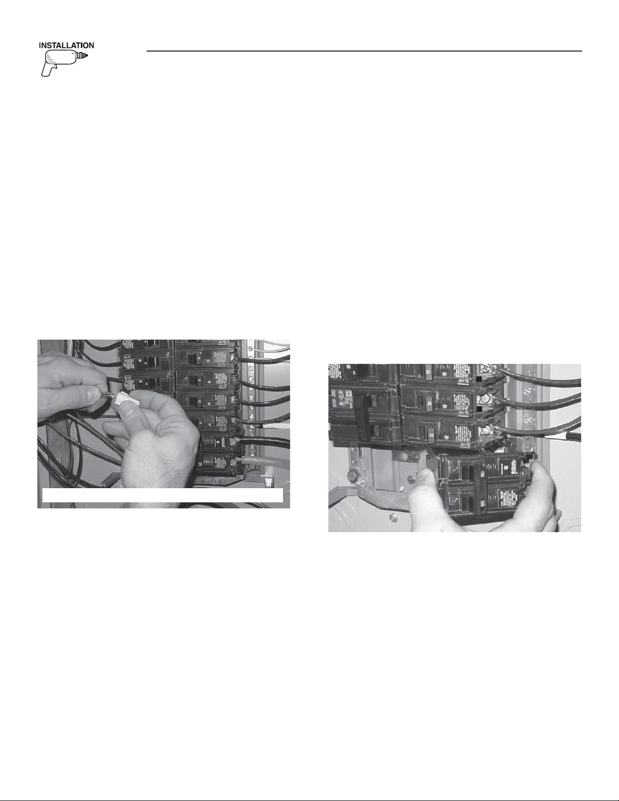
10a. Remove the main electrical distribution panel cover. Remove
appropriate size knockout from the bottom or side of the main
panel. (A 2-foot flexible conduit is pre-wired from the manual
transfer switch with built-in load center). Remove threaded lock
nut from conduit coupling. Feed all wires through knockout into
main panel. Slip lock nut over wires and tighten securely onto
conduit coupling (Figure 33).
Figure 33 - Connect Emergency Circuits
Trace each black (hot) wire connected and wire nut the white (neutral)
wire from the same Romex cable (circuit) to the matching circuit
number on the white (neutral) wire from the emergency load center.
Repeat for each circuit.
The emergency load center in the transfer switch supplies the following
circuits: (5) 15A/120V, (5) 20A/120V, (1) 20A/240V, (1) 40A/240V and
(1) 50A/240V.
11. Install the 60 Amp double pole circuit breaker that you have
purchased into main electrical distribution panel (Figure 34).
This circuit breaker must be compatible with your main
electrical distribution panel. It may be necessary to reposition
remaining circuit breakers or remove circuit breakers that have
been disconnected to accommodate the insertion of the 60
Amp double pole circuit breaker. Connect white wire to the main
distribution panel neutral bar. Connect solid green wire to main
electrical panel ground bar. Connect the black and red wires
to the 60 Amp double pole circuit breaker. Replace electrical
distribution panel cover.
Figure 34 - Connect Emergency Circuits
60
UL approved wire nuts are included with installation kit.
NOTE:
Circuits to be moved must be protected by same size breaker.
For example, a 15 amp 120V circuit in emergency load center will
replace a 15 amp 120V circuit in main panel.
NOTE:
Both grounded and ungrounded conductors for each circuit must
be moved to the emergency panel and connected to to the new
wiring from the emergency panel using supplied locknuts.
10b. In your main panel, remove the black (hot) wire from a circuit
breaker that protects a circuit you want to have powered in the
event of a power failure. Wire nut the black wire to the matching
circuit lead wire from the emergency circuit breaker from load
center in the transfer switch. (All circuit wires are color coded
and labeled for easy identification). Repeat this process with
remaining circuits to be powered by the generator.
60
Your Portable Generator Manual
Transfer Switch is now installed.
NOTE:
If additional circuits are required to be protected. The manufacturer
offers an additional 30A manual transfer switch and 30A Power
Inlet Kit (Model 5341). Contact your place of purchase for
availability.
22
Page 25

33HP 990cc
Section 6 — Operation of Generator with Manual Transfer Switch
Portable Generator System
6.1 USING THE PORTABLE GENERATOR
AND TRANSFER SWITCH
The generator along with the manual transfer switch gives you the
ability to provide power safely and conveniently to vital items in your
home including hard wired items. Included in the kit is a power Inlet
box with built-in 50 Amp twistlock male receptacle and a 15 foot
electrical power cord. The power cord is made up of 4 wires, power
(black & red), neutral (white) and ground (green). At one end is the
50 Amp female receptacle which is inserted and twist-locked into the
power inlet box.
At the other end is the male connector (NEMA 14-50) which plugs into
the portable generator’s control panel and is locked in place by the
supplied spring retainer.
NOTE:
The power inlet box must be locked to ensure safety and to
discourage tampering.
Power Inlet Box
with 50 Amp Male
Receptacle
17,500 Watt Ultra Source Portable Generator
Generator Control Panel
12 Volt DC Receptacle
15 Foot Power Cord with 50 Amp Plug and Receptacle
NEMA 14-50, 50 Amp Plug
POWERFUL: Superior motor-starting
capabilities starts a 5-ton air conditioner
LONG LIFE ENGINE: Full pressure
lubrication and spin-on oil filter
GENERAC® POWER SYSTEMS, INC.
SAFE POWER: Electronic governor, automatic
voltage regulation and automatic idle control
LONG RUN-TIME: 16 gallon fuel tank features
10 hour run-time at half load
NEMA 14-50, 50 Amp Receptacle
Retaining
Clip
23
Page 26

Section 6 — Operation of Generator with Manual Transfer Switch
Portable Generator System
6.2 TRANSFER TO GENERATOR POWER
SOURCE WHEN UTILITY POWER
FAILS
1. Move generator to within approximately 10 feet of the power inlet
box. Connect ground strap to the generator’s grounding lug and
to the grounding rod.
2. Open the door of the Manual Transfer Switch. Slide the
mechanical interlock connecting the 60 Amp and 50 Amp circuit
breakers at the top of the panel to turn “Off” the “Utility” circuit
breaker. Both circuits will be in the “Off” position.
3. Flip the “Standby” circuit breaker handle to the “On” position.
Close the door of the Manual Transfer Switch.
4. Open the power inlet box. Insert and lock the 50 Amp female
receptacle into the male receptacle in the external connection
box. Insert the 50 Amp plug into the 50 Amp NEMA 14-50
receptacle located on the underside of the generator’s control
panel. A retaining clip is supplied on the control panel. Secure the
retaining clip over the end of the plug. The retaining clip ensures
that the plug remains in place during generator operation.
5. Before starting the generator, verify the 50 Amp circuit breaker on
the generator’s control panel is in the “Off” or “Open” position.
6. Start the generator and allow it to warm up for a couple of
minutes. Switch the 50 Amp circuit breaker on the generator
control panel to the “ON” or “Closed” position.
7. The generator is now supplying power to the load center circuits
in the manual transfer switch.
6.3 TRANSFER BACK TO UTILITY POWER
SOURCE
When utility power has been restored, you will want to transfer back
to that power source and shut down the generator. This can be
accomplished as follows:
1. Switch the 50 Amp circuit breaker on the generator control panel
to the “OFF” or “Open” position.
2. Release the retainer clip from the NEMA 14-50 plug and remove
the plug from the outlet on the generator. Twist and remove
the 50 Amp female receptacle from the power inlet box. Close
and lock the box. Coil the power cord and place it with the
generator.
3. After the generator has run for a couple minutes to cool down,
turn off the generator.
4. Open the door of the Manual Transfer Switch and slide the
mechanical interlock to turn “OFF” the “STANDBY” circuit
breaker. Both circuit breakers will be in the “OFF” position.
5. Flip the “UTILITY” circuit breaker handle to the “ON” position.
Close the door of the Manual Transfer Switch.
6. The Utility is now supplying power.
7. Disconnect the ground strap from the grounding rod and the
generator’s grounding lug. Retain the ground strap with the
generator. Return the generator to its storage location.
Choose a lamp or light fixture located in a frequently
occupied area of the building as a signal light to tell
you when utility power has been restored. This light
should be on a utility powered circuit only, so it operates
independent of the generator.
24
Page 27

Section 7 — Notes
Portable Generator System
25
Page 28

Section 7 — Notes
Portable Generator System
26
Page 29

Section 8 — Electrical Data
Installation Diagram - Drawing No. 0G0907-B
27
Page 30

Section 8 — Electrical Data
ACTUATOR
GOVERNOR
30
85
87a
86
87
SC
BLACK
12V
BATTERY
SM
RED
SP2
SP1
IM2
FSS
LOP
D
D
IM1
STOP
RUN
(START)
0
IC
PIN #
12
11
10
8
9
7
6
SCR
5
4
3
0
2
1
F1
GND
SSR
ENGINE WIRING
30A
C.B.
22
C.B.
30A
0
22
22
G
0
0
TWISTLOK
120V/30A
WHITE
22
0
0
G
WHITE
TWISTLOK
120V/30A
20A
C.B.
C.B.
20A
C.B.
30A
30A
C.B.
LOAD
LINE
WHITE
HOT
3
HOT
1
WHITE
0
5
4
2
HOT
3
1
HOT
DUPLEX
120V/20A
120/240V
30A TWISTLOK
WHITE
0
4
5
WHITE
2
WHITE
120V/20A
GFCI
X
Y
G
C.B.
CONTROL
SWITCH
IDLE
ON/OFF
60A
(50A/60A) OUTLET
120/240V
50A/
22
11
44
83
167
229
15B
0
86
86
15B
229
14
167
0
86
0
14
0
0
15
15
0
55A
55
0
14
18
14
44A
11A
44A
11A
44
22
44
44
44
11
11
11
11
44
11
44
44B4444
11B1111
22
0
0
22
22
11B
0
11B
0
0
0
44
44
0
11A
00000
0 0 0
55
0
0
0
13
15
16
17
14
13
14
17
15
86
167
0
15
18
0
15
15
0
0
15
15
0
44
11
11
44
11C
11D
44D
44C
44C
11C
11D
44D
22
22
22
22
22
22
22
22
0
22
0
14
14
13
910101212
5
1 264
8
18
15
0
14
86
15
16
0
15
13
167
0
18
15
86
17
14
13
13
16
13
17
83
167
229
15B
0
000
-
+
OFF
ON
GREEN
WHITE
X
Y
22
11
44
15B
229
14
167
0
86
0
0
15
15
0
55A
55
0
14
Wiring Diagram, Portable Generator – Drawing No. 0G0731
28
WHITE
22
22
44D
44D
ENGINE WIRING
SP1
SP2
30A
C.B.
22
44
BLACK
120V/30A
TWISTLOK
IM1
IM2
BATTERY
22
12V
22
87a
11B
11B
44
11
11
44
30
30A TWISTLOK
WHITE
22
22
44B
11B
17
87
85
SCR
120/240V
22
30A
C.B.
30A
C.B.
F1
14
22
44
15
11A
44
44
44
11
11
44
11
11A
18
15
15
120V/30A
TWISTLOK
WHITE
11D
30A
11D
C.B.
11C
20A
11C
C.B.
11
GOVERNOR
ACTUATOR
120V/20A
DUPLEX
22
HOT
HOT
22
WHITE
22
WHITE
44C
11
20A
44C
C.B.
HOT
LOAD
WHITE
HOT
LINE
WHITE
22
22
44
120V/20A
GFCI
22
22
IC
18
15
(START)
RUN
STOP
LOP
0
86
14
15
17
167
86
13
14
17
FSS
16
15
13
RED
SM
SC
13
16
13
PIN #
18
15
167
86
13
15
14
17
16
15
86
15
10
11
13
12
50A/
14
55
60A
C.B.
15
GND
120/240V
(50A/60A) OUTLET
GREEN
WHITE
22
111144
ON
OFF
44A
11A
14
18
SSR
14
13
44A
22
11
44
15B
229
14
167
86
15
15
55A
55
14
Page 31

4
0
CLOSEST TO BEARING
STATOR
66
REGULATOR
VOLTAGE
12Vdc OUTLET
RESET BKR
10A AUTO
162
6
4
0
162
11S
22S
SCR - STARTER CONTACTOR RELAY
TB1, TB2 - TERMINAL BLOCK
SSR - START / STOP RELAY
SP2 - SPARK PLUG, CYL. 2
SP1 - SPARK PLUG, CYL. 1
SM - STARTER MOTOR
SC - STARTER CONTACTOR
R1 - 25 OHM, 25W RESISTOR
IM2 - IGNITION MODULE, CYL. 2
FSS - FUEL SHUT OFF SOLENOID
CB1 - 6AMP AUTO RESET BREAKER
LOP - LOW OIL PRESSURE
IM1 - IGNITION MODULE, CYL. 1
GND - GROUND BAR
F1 - 10A FUSE
D2 - 600V 12A DIODE
D - ENGINE SHUTDOWN DIODE
BA - BRUSH ASSEMBLY
LEGEND
RECTIFIER
CHARGE
BATTERY
CHARGE
BATTERY
RECTIFIER
D2
R1
22
ENGINE SHUTDOWN P.C.B.
ELECTRONIC GOVERNOR /
CONTROL
SWITCH
IDLE
ON/OFF
22S
55
11S
55A
TB2
TB1
BLK
CB1
BLK
RED
1
2
11
44
IDLE CONTROL
TRANSFORMERS
8
PIN #
12
10
11
9
BA
77A
5
7
6
66A
4
3
2
66
55
77
6
55A
22S
11S
22
77
4
0
77A
66A
77
66 6
55
2
55A
22S
11S
44
11
11
22
22
11
44
44
83
167
229
15B
0
86
86
15B
229
14
167
0
86
0
14
0
0
15
15
0
55A
55
0
14
83
167
229
15B
0
13A
15
15
15
15
55A
55
0
14
66A
77A
4
66
77A4
0
66A 6
77
0
15A
13A
0
15A
0
14
0
14
14
14
162
55
55A
J1
J2
Section 8 — Electrical Data
Wiring Diagram, Portable Generator – Drawing No. 0G0731
22
IDLE CONTROL
TRANSFORMERS
22
11
11
22
11
44
83
167
ON/OFF
IDLE
CONTROL
SWITCH
15B
229
14
167
86
55A
15
15
55
14
229
86
15B
83
167
229
15B
86
ELECTRONIC GOVERNOR /
ENGINE SHUTDOWN P.C.B.
14
14
55A
55
15
15
RED
44
BLK
BLK
TB1
101211 896745231
J2
J1
VOLTAGE
REGULATOR
14
11S
22S
162
15A
44
TB2
11S
22S
10A AUTO
RESET BKR
13A
55A
55A
162
55
162
55
11S
22S
55A
55
CB1
14
15A
11
44
77A
66A
77A
66A
12Vdc OUTLET
22
11S
22S
55A
77A
66A
55
66
77
66
77
14
66
77A
15
15
66A
77
13A
66
10
11
12
PIN #
14
R1
D2
BATTERY
CHARGE
RECTIFIER
BATTERY
CHARGE
RECTIFIER
STATOR
77
CLOSEST TO BEARING
BA
LEGEND
BA - BRUSH ASSEMBLY
CB1 - 6AMP AUTO RESET BREAKER
D - ENGINE SHUTDOWN DIODE
D2 - 600V 12A DIODE
F1 - 10A FUSE
FSS - FUEL SHUT OFF SOLENOID
GND - GROUND BAR
IM1 - IGNITION MODULE, CYL. 1
IM2 - IGNITION MODULE, CYL. 2
LOP - LOW OIL PRESSURE
R1 - 25 OHM, 25W RESISTOR
SC - STARTER CONTACTOR
SCR - STARTER CONTACTOR RELAY
SM - STARTER MOTOR
SP1 - SPARK PLUG, CYL. 1
SP2 - SPARK PLUG, CYL. 2
SSR - START / STOP RELAY
TB1, TB2 - TERMINAL BLOCK
29
Page 32

Section 8 — Electrical Data
86
0
14
15
15
167
0
17
16
13
13
22
44
ACTUATOR
J1
44C 0
GFCI
120V
120V/30A
TWISTLOK
CB1 - 10AMP AUTO RESET BREAKER
BCR2 - BATTERY CHARGE RECTIFIER
D2, D3 - ENGINE SHUTDOWN DIODE
CB2 - 6AMP AUTO RESET BREAKER
BCR1 - BATTERY CHARGE RECTIFIER, 10A
30A
LEGEND
BA - BRUSH ASSEMBLY
F1 - 10A FUSE
D1 - 600V 12A DIODE
22
44
0
11
11C2222 0
22
120V
DUPLEX
11S
11
12
J2
120V/30A
C.B.
44D
TWISTLOK
0
11D
22
22
SC - STARTER CONTACTOR
R1 - 25 OHM, 25W RESISTOR
IM2 - IGNITION MODULE, CYL. 2
FSS - FUEL SHUT OFF SOLENOID
LOP - LOW OIL PRESSURE
IM1 - IGNITION MODULE, CYL. 1
GND - GROUND BAR
I.C.T. - IDLE CONTROL TRANSFORMER
22
0
44
11
C.B.
50A/60A
120/240V
TWISTLOK
30A
22
50A/60A
0
11A
22
120/240V
11B
14
15
C2-7
C2-2
BATTERY CHARGE WINDING
10A BATTERY CHARGE WINDING
TB1
15B
15B
86
0
0
86
83
167
229
229
167
VOLTAGE
REGULATOR
ELECTRONIC
C1-10
77A
77
77
C1-8
55
C1-5
77A
C1-3
55A
CONTROL
PRINTED CIRCUIT
167
5
229
TR2
86
22S
8
9
10
6
7
83
TR1
0
15B
2
3
4
1
BOARD
11S
22S
11S
TB2
22S
18
GOVERNOR
C2-1
D3
D2
15
15B
4 6
18
15B
12
0
5
14
14
229
10 9
15
13
SSR
15
0
BLK
BLK
83
167
229
15B
0
86
162
6
77
11S
22S
4
BLK
77
BCR1
66
01515
IM2
SP2
IM1
SP1
167
D1
R1
14
15
4
15
17
C2-10
15
167
C2-4
0
17
C2-3
C2-8
F1
15
SCR
16
13
C2-9
C2-11
13
C2-6
0
15
83
167
SW2
0
86
162
6
CB2
0
2
BCR2
4
13A
66A
77A
CB1
15
15A
0
C2-12
0
0
86
C2-5
15
12Vdc
0
0
POWER WINDING
66
66
C1-9
11S
66A
C1-4
66A
11S
I.C.T.
11
BLK
22S
RED
I.C.
I.C.T.
C1-2
44
2 6
DPE WINDING
C1-7
C1-6
2 6
SCR - STARTER CONTACTOR RELAY
SW1 - START-RUN-STOP RELAY
SSR - START / STOP RELAY
SP2 - SPARK PLUG, CYL. 2
SP1 - SPARK PLUG, CYL. 1
SW2 - IDLE CONTROL SWITCH
TB1, TB2 - TERMINAL BLOCK
SM - STARTER MOTOR
0
11
44A 0
0
FSS
SW1
0
15
17
0
SC
SC
SM
BATTERY
BLACK
12V
RED
0
LOP
0
4
C1-12
4
22
0
11
44
FIELD
C1-11
4
BA
0
0
11S
22S
22S
22
22
22S
11B
C.B.
20A
C.B.
30A
C.B.
30A
C.B.
30A
C.B.
20A
0
Electrical Schematic, Portable Generator – Drawing No. 0G0733
BATTERY CHARGE WINDING
77A
C1-5
C1-3
10A BATTERY CHARGE WINDING
77
C1-10
C1-8
77
77A
ELECTRONIC
VOLTAGE
REGULATOR
15B
86
167
86
8383229
83
229
15B
167
120V
GFCI
RESET
RESET
TEST
55A
55
TEST
TB1
15B
TR1
167
86
TB2
TR2
229
POWER WINDING
66A
11S
11
66A
11S
22S
11S
CONTROL
BOARD
C1-1
BLK
J1
229
15B
I.C.T.
BLK
18
C1-4
66
C1-9
66
77
11S
22S
162
86
15B
229
167
83
BLK
BLK
11S
22S
11S
22S
83
11S
22S
10
11
12
PRINTED CIRCUIT
J2
66
77
15
12
15B
BLK
BCR1
10
18
C1-2
11
15
14
C2-1
22S
RED
22S
22S
15
13
SSR
14
229
GOVERNOR
ACTUATOR
22
I.C.
22
66A
77A
13A
162
86
167
83
15
15
14
D2
IM1
D3
IM2
CB1
CB2
SW2
I.C.T.
BCR2
SP1
SP2
44
15A
D1
R1
1414167
15
120V
DUPLEX
22
120V/30A
TWISTLOK
22
120V/30A
TWISTLOK
22
120/240V
TWISTLOK
30A
DPE WINDING
C1-6
15
15
SCR
17
15
11B
12Vdc
C1-7
F1
86
13
13
16
17
167
15
15
14
C2-5
86
C2-12
C2-6
13
C2-11
13
C2-9
16
C2-8
17
C2-3
C2-4
167
C2-10
15
C2-2
C2-7
120/240V
50A/60A
C1-11
SW1
15
14
BA
FIELD
C1-12
44
22
11
LOP
RED
SC
BATTERY
12V
SM
BLACK
SC
17
15
FSS
30
44C
C.B.
20A
11C
C.B.
20A
22
11
22
44
LEGEND
BA - BRUSH ASSEMBLY
BCR1 - BATTERY CHARGE RECTIFIER, 10A
BCR2 - BATTERY CHARGE RECTIFIER
CB1 - 10AMP AUTO RESET BREAKER
CB2 - 6AMP AUTO RESET BREAKER
D1 - 600V 12A DIODE
D2, D3 - ENGINE SHUTDOWN DIODE
F1 - 10A FUSE
44D
11D
C.B.
30A
C.B.
30A
044B
C.B.
30A
11
22
44
FSS - FUEL SHUT OFF SOLENOID
GND - GROUND BAR
I.C.T. - IDLE CONTROL TRANSFORMER
IM1 - IGNITION MODULE, CYL. 1
IM2 - IGNITION MODULE, CYL. 2
LOP - LOW OIL PRESSURE
R1 - 25 OHM, 25W RESISTOR
SC - STARTER CONTACTOR
11B
C.B.
30A
11A
44A
22
C.B.
50A/60A
11
22
44
SCR - STARTER CONTACTOR RELAY
SM - STARTER MOTOR
SP1 - SPARK PLUG, CYL. 1
SP2 - SPARK PLUG, CYL. 2
SSR - START / STOP RELAY
SW1 - START-RUN-STOP RELAY
SW2 - IDLE CONTROL SWITCH
TB1, TB2 - TERMINAL BLOCK
Page 33

Section 8 — Electrical Data
CIRCUIT 16
CIRCUIT 14
CIRCUIT 12
CIRCUIT 8
CIRCUIT 6
MAIN 2
CIRCUIT 2
CIRCUIT 4
CIRCUIT 10
NEUTRAL
NEUTRAL
NEUTRAL
CIRCUIT 12
CIRCUIT 14
CIRCUIT 16
CIRCUIT 8
NEUTRAL
NEUTRAL
CIRCUIT 6
NEUTRAL
CIRCUIT 10
MAIN 1
GROUND
NEUTRAL
CIRCUIT 9
NEUTRAL
NEUTRAL
NEUTRAL
NEUTRAL
CIRCUIT 13
CIRCUIT 11
CIRCUIT 3
CIRCUIT 1
CIRCUIT 7
CIRCUIT 5
CIRCUIT 15
CIRCUIT 15
CIRCUIT 11
GROUND BAR
(ORG)
(LT BLU)
(DRK BLU)
(PNK)
(YEL/WHT)
(YEL)
(BRN/WHT)
(BRN)
(WHT)
(WHT)
(WHT)
(WHT)
(WHT)
(GRN)
(ORG)
(ORG/WHT)
(BLU/YEL)
(ORG/YEL)
(GRY/YEL)
(VIO/YEL)
(VIO)
(PNK/YEL)
(RED)
(BLK)
(WHT)
(WHT)
(WHT)
(WHT)
(WHT)
(WHT)
CIRCUIT 9
CIRCUIT 13
GROUND(GRN)*
GEN2(RED)*
GEN1(BLK)*
NEUTRAL(WHT)*
*-CUSTOMER SUPPLIED
LOAD CENTER
NEUTRAL BAR
NEUTRAL BAR
Wiring Diagram, Manual Transfer Switch – Drawing No. 0G1065
CIRCUIT 9
CIRCUIT 11
CIRCUIT 13
CIRCUIT 15
CIRCUIT 1
CIRCUIT 3
CIRCUIT 5
CIRCUIT 7
CIRCUIT 9
CIRCUIT 11
CIRCUIT 13
CIRCUIT 15
GROUND
NEUTRAL
NEUTRAL
NEUTRAL
NEUTRAL
NEUTRAL
(BRN/WHT)
(YEL/WHT)
(LT BLU)
(DRK BLU)
(GRN)
(WHT)
(WHT)
(WHT)
(WHT)
(WHT)
(BRN)
(YEL)
(ORG)
(PNK)
GROUND BAR
STANDBY
GROUND(GRN)*
GEN2(RED)*
GEN1(BLK)*
NEUTRAL(WHT)*
*-CUSTOMER SUPPLIED
NEUTRAL BAR
LOAD CENTER
CIRCUIT 16
CIRCUIT 14
CIRCUIT 12
CIRCUIT 10
CIRCUIT 8
CIRCUIT 6
CIRCUIT 4
CIRCUIT 2
CIRCUIT 16
CIRCUIT 14
CIRCUIT 12
CIRCUIT 10
CIRCUIT 8
CIRCUIT 6
(PNK/YEL)
(BLU/YEL)
(ORG/YEL)
(GRY/YEL)
(VIO/YEL)
(ORG/WHT)
MAIN 2
MAIN 1
NEUTRAL
NEUTRAL
NEUTRAL
NEUTRAL
NEUTRAL
NEUTRAL
UTILITY
NEUTRAL BAR
(VIO)
(ORG)
(RED)
(BLK)
(WHT)
(WHT)
(WHT)
(WHT)
(WHT)
(WHT)
31
Page 34

Section 9 — Exploded Views and Parts Lists
Manual Transfer Switch with Load Center – Drawing No. 0G0939-B
32
Page 35

Section 9 — Exploded Views and Parts Lists
Manual Transfer Switch with Load Center – Drawing No. 0G0939-B
ITEM PART NO. QTY. DESCRIPTION
1 0G0749 1 BOX LOAD CENTER W/HARDWARE
2 0G0748 1 CIRCUIT BREAKER INTERLOCK
3 0E7888 1 CIRCUIT BREAKER 20A 2P
4 0E7888B 5 CIRCUIT BREAKER 15A 1P
5 0E7888C 5 CIRCUIT BREAKER 20A 1P
6 0E7888D 1 CIRCUIT BREAKER 40A 2P
7 0E7888E 2 CIRCUIT BREAKER 50A 2P
8 0E7888F 1 CIRCUIT BREAKER 60A 2P
9 0G0863 1 HARNESS, 50 AMP PLUGS
10 0G0750 1 HARNESS, LOAD CENTER TO MAIN PANEL
11 0G1494 1 POWER INLET BOX
33
Page 36

Section 9 — Exploded Views and Parts Lists
GT-990 & GT-760 Engine (Page 1) – Drawing No. 0E8589-Y
34
Page 37

Section 9 — Exploded Views and Parts Lists
GT-990 & GT-760 Engine (Page 1) – Drawing No. 0E8589-Y
ITEM PART NO. QTY. DESCRIPTION
1 0C5729 1 ASSEMBLY, CRANKCASE HOUSING
WITH SLEEVE
2 0E9843 1 SEAL, 38 I.D. CRANKSHAFT
3 090388 3 SCREW, TAPTITE M6-1.0 X 12 BP
4 0C5372 1 ASSEMBLY, BREATHER
5 0C3005 1 GASKET, BREATHER COVER
6 0E3372B 1 SEPARATOR, OIL BREATHER
7 0D8067A 1 ASSEMBLY, HEAD #1
8 071983 4 RETAINER, PISTON PIN 20
9 0G0693 1 ASSY, ROCKER COVER W/BARB
10 043790 1 BARBED EL 90 3/8NPT X 3/8
11 0E2950 2 PISTON, LC (GT-990)
0E2985 2 PISTON, HC (GT-760)
12 021533 2 SET, PISTON RING 90MM
13 0E1466 2 PIN PISTON
14 0D4041 1 ASSEMBLY, CAMSHAFT & GEAR
16 093064 1 ASSEMBLY, OIL FILL CAP
17 0C2977 1 GASKET, CRANK CASE
18 0C5943 1 SEAL, OIL PASSAGE
19 0E3791E 1 ASSEMBLY, CRANKSHAFT
HORIZONTAL DIRECT DRIVE (GT-
990)
0E3790E 1 ASSEMBLY, CRANKSHAFT
HORIZONTAL DIRECT DRIVE (GT-
760)
20 0E3223 2 ASSEMBLY, CONNECTING ROD (GT-
990)
0E3222 2 ASSEMBLY, CONNECTING ROD (GT-
760)
21 0D2157 2 SCREW SHC M6-1.0 X 50 G8.8
22 0E6098 1 SCREEN, OIL PICKUP
23 0G1536 1 ASSEMBLY, OIL PUMP
24 0E8152 1 O-RING, 0.49 ID X 0.07 THICK
25 0C3011 2 COVER, OIL RELIEF
26 0C3009 2 SPRING, OIL RELIEF
27 0C3010 2 BALL, 1/2D OIL RELIEF
28 093873 2 WASHER, LOCK RIB M6
29 0F5458 1 SCREW, PLASTITE HI-LOW #10
30 0C5998 1 CLAMP, OIL TUBE
31 0D4497 1 PLUG-CRANKCASE GOVERNOR
BORE
ITEM PART NO. QTY. DESCRIPTION
32 0C3971E 1 ASSEMBLY, DIPSTICK WITH
HANDLE
33 0D3745 1 TUBE, DIPSTICK
34 0C3027 3 O-RING, OIL CLR
35 0E9842 1 SEAL, 42 I.D. CRANKSHAFT
36 0C5731 1 ASSEMBLY, GEAR COVER W/
SLEEVE
37 0C3006 10 SCREW, HHFC M10-1.5 X 55
38 080318 8 SCREW HHFC M6-1.0 X 25
39 0G1839 2 LIFT HOOK, GT990/760
40 0D2723D 1 COVER, ROCKER W/OIL FILL
“GENERAC” TEXT
41 0C2979 2 GASKET, VALVE COVER
42 086515 8 KEEPER, VALVE SPRING
43 0D2274 4 RETAINER, VALVE SPRING
44 0D3867 4 SPRING, VALVE
45 078672 2 SEAL, VALVE STEM D7
46 0C5371 4 WASHER, VALVE SPRING
47 072694 4 STUD, ROCKER ARM PIVOT
48 0C3027 2 O-RING, 3/8” X 1/2”
49 0D5313 4 ROCKER ARM
50 0D3998 4 NUT, HEX M8-1.0 GB YELLOW
CHROM
51 0D6024 2 PLATE, PUSH ROD GUIDE
52 0C2976 12 SCREW HHFC M8-1.25 X 65
53 086516 2 VALVE, EXHAUST
54 0C2229 2 VALVE, INTAKE
55 083897 4 TAPPET, SOLID
56 0D8067B 1 ASSEMBLY, HEAD #2
57 0D9853D 4 PUSHROD 147
58 0C2978 2 GASKET, HEAD
59 0D6008 1 KIT GEAR COVER
60 0D4010 1 KIT GASKET
61 0D6007 1 KIT PISTON & RINGS
62 0D4012 1 KIT BREATHER ASSEMBLY
63 0D8675A 1 KIT HEAD ASSEMBLY CYLINDER 1
64 0D8675B 1 KIT HEAD ASSEMBLY CYLINDER 2
65 0D4015 1 KIT OIL RELIEF
35
Page 38

Section 9 — Exploded Views and Parts Lists
GT-990 & GT-760 Engine (Page 2) – Drawing No. 0E8589-Y
36
Page 39

Section 9 — Exploded Views and Parts Lists
GT-990 & GT-760 Engine (Page 2) – Drawing No. 0E8589-Y
ITEM PART NO. QTY. DESCRIPTION
66 0D6592 1 WINGNUT, AIRBOX
67 0D4511 1 PRECLEANER, AIR
68 0D9723 1 ELEMENT, AIR CLEANER
69 0E5302 1 STUD M6-1.0 X 73
70 0D4183 1 ADAPTOR, SPIT BACK
71 0D6327 1 GASKET, SPITBACK
72 0D2774B 1 BASE, AIRBOX
73 0D5125 1 SPRING, WINTER/SUMMER VALVE
74 0D2930 1 VALVE, SUMMER / WINTER
75 0D4612A 1 SNORKEL, AIR INTAKE
76 0D6143 1 TUBE, HEAT RISER 50.8 I.D.
77 0D2775 1 COVER, AIRBOX
78 0D5014A 1 KNOB, AIRBOX 17mm
79 0D5014B 1 KNOB, AIRBOX 95MM
80 049721 1 SCREW HHC M6-1.0 X 35
81 022097 1 WASHER LOCK M6-1/4
82 022473 1 WASHER FLAT 1/4
83 0E8388 4 NUT, HEX FLANGE WHIZ M6-1.0
84 0D6021 4 STUD, METRIC
85 0C9093A 1 HOSE, BREATHER
86 0D4522 1 CONTROLLER ASSEMBLY
87 074908 2 SCREW HHTT M5-0.8 X 10
89 0E3398 1 ASSEMBLY, WIRE
90 0F9035 1 CARBURETOR (GT-990)
0F8603 1 CARBURETOR (GT-760)
91 0D4026 1 GASKET, CARB TO SPACER (GT-
990)
0D4024 1 GASKET, CARB/AIRBOX (GT-760)
92 048031C 4 CLAMP HOSE BAND 1/4
93 0F9176 12” HOSE ¼ ID
94 0D4023 1 GASKET, MANIFOLD TO CARB (GT-
990)
0D5282 1 GASKET, MANIFOLD TO CARB (GT-
760)
95 084409D 1 SLEEVING, FLEXO HW ¾ 3”
96 0D6313 1 FILTER, FUEL
97 070008 4 WASHER FLAT M8
98 070006 4 WASHER LOCK M8
99 049821 4 SCREW SHC M8-1.25 X 30
100 0C9911 1 MANIFOLD, INTAKE
101 051714 1 NUT HEX M3-0.5
102 0D5411 1 ROD, SUMMER / WINTER VALVE
103 0D5445 1 BUSHING, MINI CONTROL PANEL
104 0D5416A 1 KNOB, CONTROL SUMMER /
WINTER
105 0D5398 1 CHOKE ASSEMBLY
106 0E6043 2 SCREW TAPTITE M5-0.8 X 8 ZP
107 0D3432 1 PANEL, CONTROL FACE PLATE
108 045756 24 SCREW TAPTITE M6-1.0X 10
YELLOW CHROME
109 0D4767 1 SWITCH ROCKER
110 0D1142A 1 WRAPPER, LOWER CYLINDER 2
111 0D1143 1 WRAPPER, UPPER CYLINDER 2
ITEM PART NO. QTY. DESCRIPTION
112 0F1177 1 ASSEMBLY, GROUND WIRE
113 022097 4 WASHER LOCK M6-1/4
114 0G3111 4 SCREW TAPTITE M6-1.0 X 25 ZINC
115 0F1338B 1 ASSY, IGN COIL W/DIODE NO ADV
116 0F6263 1 PUMP, IMPULSE
117
118 0G0926 2 SCREW, HHFCS M6-1.0 X 16 G8.8
119 0G0832 1 ELBOW, RUBBER 90 DEG.
GASOLINE
120 0E7585A 2 SPARKPLUG, CHAMPION RC14YC
121 0E4271 1 STARTER, DELCO REMY SD80
122 022129 3 WASHER LOCK M8-5/16
123 061906 2 SCREW HHC M8-1.25 X 85 G8.8
124 022145 1 WASHER, FLAT M8
125 0F5467 1 NUT, HEX M8-1.25 YELLOW ZINC
126 0D1131 1 GUARD,FAN
127 0F1169B 1 HOUSING, BLOWER GAS COOLER
128 0C9763 4 NUT, GROMMET 1/4 PLUG
129 0C3034 1 NUT,HEX M24
130 0C3033 1 WASHER, M24
131 0C3032 1 PLATE, FAN
132 0A5992 2 WASHER SHAKEPROOF INT M8 SS
133 051754 2 SCREW HHC M8-1.25 X 12 G8.8
134 0C3031 1 FAN, NYLON
135 0E4997 1 ASSY,GROUND WIRE CONNECTOR
136 045756 4 SCREW TAPTITE M6-1X10 YELLOW
CHROME
137 0C3725A 1 FLYWHEEL ASSEMBLY
138 0F1170A 1 PLATE, BACKING GT990 W/OIL
COOL
139 082774 1 KEY, WOODRFF 4 X 19D
140 0C3043 2 GASKET, MANIFOLD / PORT
141 0C9764 4 PLASTITE,1/4-15 X 3/4
142 0E9506 1 COOLER, OIL
143 0F6301 4 CLAMP, HOSE OETIKER 16.5mm
144 0F0452C 2 HOSE 3/8” 300PSI 6” LONG OIL
145 035461 2 BARBED STR 1/4NPT X 3/8
146 070185B 1 OIL FILTER
147 0G4403 1 ASSY OIL DRAIN HOSE
149 0C3025 1 SWITCH, OIL PRESS
150 0D4550 1 BRACKET, AIRBOX SUPPORT
151 0C3018 1 WRAPPER, UPPER CYLINDER 1
152 0C3019 1 WRAPPER, LOWER CYLINDER 1
153 046964 1 BRASS ST ELBOW 1/4 NPT
154 0E0409 1 ASSY, ROD, GOV. STEPPER MOTOR
155 0C8563 6 SCREW HHHC M6-1.0 X12
157 0D9784 2 NUT, LOCK HEX M3-0.5 (GT-990)
0E4869 2 NUT, HEX W/TOOTH WASHER M3-
0.5 (GT-760)
160 0D6147 7 SCREW HHFC M6-1.0 X 10mm
161 0F1338A 1 ASSY, IGN COIL W/DIODE NO ADV
162 048031G 1 CLAMP, HOSE BAND GREEN
163 0D6342 2 BALL STUD
37
Page 40

Section 9 — Exploded Views and Parts Lists
Generator – Drawing No. 0G0742-A
38
Page 41

Section 9 — Exploded Views and Parts Lists
Generator – Drawing No. 0G0742-A
ITEM PART NO. QTY. DESCRIPTION
1 0C6934 1 ADAPTOR, ENGINE
2 0G1177 1 STATOR 15KW
0D2136 STATOR 17.5KW
3 0G11760SRV 1 ASSEMBLY, ROTOR WITH FAN 15KW
0D21350SRV ASSEMBLY, ROTOR WITH FAN 17.5KW
4 0C6043B 1 CARRIER, REAR BEARING
5 0D2492 1 EXHAUST MANIFOLD
6 0D2726 1 MUFFLER
7 0C4138 2 GASKET, EXHAUST
8 0D3547 1 COVER, ALTERNATOR AIR IN
9 031971 1 BEARING
10 0C3168 3 5/16 SPECIAL LOCK WASHER
11 0D1838 1 SCREW IHHC 3/8-24 X 15.50 G5
12 0D3549 4 SCREW IHHC M8-1.25 X 400 G8.8
13 0C7038E 1 BRACKET, ALT MOUNTING
14 032712 4 SCREW HHTT #10-32 X 1.75
15 0D4662 1 SCREW HHTT M8-1.2 X 20
16 0C7038D 1 ENGINE MOUNTING PLATE
17 0C7758 6 RUBBER MOUNT
18 0388050AF0 1 BATTERY CABLE, BLACK
19 0C2417A 1 EARTH STRAP 3/8X 3/8
20 082121C 1 CLIP-J VINYL COAT .625 ID
21 066386 1 ASSEMBLY, BRUSH HOLDER
22 0C2824 1 SCREW TAP-R #10-32 X 9/16
23 0A2038 1 WASHER FLAT 3/8 ZINC
24 022237 5 WASHER LOCK 3/8
25 022511 4 SCREW HHC 3/8-16 X 1-1/4 G5
26 022131 4 WASHER FLAT 3/8-M10 ZINC
27 051731 4 SCREW HHC M8-1.25 X 50 G8.8
28 022145 21 WASHER FLAT 5/16 ZINC
29 049820 4 NUT LOCK HEX M8-1.25 NYLON INSERT
30 043116 7 SCREW HHC M6-1.0 X 12
31 022129 18 WASHER LOCK M8-5/16
32 022259 12 NUT HEX 5/16-18 STEEL
33 059637 2 SCREW TAPTITE 3/8-16 X 3/4 BP
34 0D5100 1 SHIELD, MUFFLER HEAT
35 0D5823 1 U-BOLT & SADDLE
36 0C8565 4 SCREW SHC M8-1.25 X 18
37 0D5833 1 PANEL, MUFFLER BOX BACK
38 0D5834 1 PANEL, MUFFLER BOX END
39 090388 3 SCREW HHTT M6-1.0 X 12
40 022473 7 WASHER FLAT M6-1/4
41 022097 7 WASHER LOCK M6-1/4
42 0D5133 1 SPARK ARRESTOR SCREEN
43 0D5133A 1 RETAINER, SPARK ARREST SCREEN
44 045764 1 SCREW HHTT M4-0.7 X 8
45 0D6214 1 SHIELD, RUBBER MOUNT
46 066849 2 SCREW HHTT M5-0.8 X 16
39
Page 42

Section 9 — Exploded Views and Parts Lists
Control Panel – Drawing No. 0G0727-B
40
Page 43

Section 9 — Exploded Views and Parts Lists
Control Panel – Drawing No. 0G0727-B
ITEM PART NO. QTY. DESCRIPTION
1 087968 1 SWITCH, ROCKER -/0
2 090418 1 OUTLET, 12VDC SNAP
3 0D6640 1 COVER, GOVERNOR CONTROL
4 090987 6 SCREW PPHM M3-0.5 X 12
5 0D8740 1 PANEL, SHEET METAL (15 KW)
0G0309 1 PANEL, SHEET METAL (17.5 KW)
6 068868 2 OUTLET 30A 120V RECEPT
7 0G1093 4 SCREW SFILHM #8-32 X 5/8 LG
(17.5 KW ONLY)
8 043182 4 WASHER LOCK M3
9 0D9784 6 NUT HEX LOCK M3-0.5 NY INS
10 075207A 4 CIRCUIT BREAKER 30A
11 075207 2 CIRCUIT BREAKER 20A
12 0G1493 1 OUTLET 50A 250V (17.5 KW ONLY)
13 043437 1 OUTLET 30A 125/250V
14 0D4968 1 OUTLET 20A 120V DPLX
15 0D4966 1 OUTLET 20A 120V GFCI
16 0D1004E 1 CIRCUIT BREAKER 50A 400V
2POLE
17 0E6480 4 NUT HEX M4-0.5 NYINS
18 022471 4 NUT HEX #8-32 (17.5 KW ONLY)
19 0D5045 1 DIN RAIL 59.5mm LONG
20 0F9719 1 ASSY PCB VREG AIR COOLED
21 0D4409 1 ELECTRONIC GOVERNOR / IDLE
CONTROLLER
22 052844 1 RELAY PNL 12VDC SPST 30A
23 0F3100 1 RELAY 3PDT 12VDC
24 0G0503 1 CONTROL PANEL BOX (15 KW)
0F7424 1 CONTROL PANEL BOX (17.5 KW)
25 023484S 1 BUSHING SNAP
26 0A1661 2 RIVET POP .156 X .160-.164 / #20
27 048766 1 BLOCK TERMINAL 20A 2 X 6 X
1100V
28 0D3550 1 BLOCK DOUBLE ROW TERMINAL 8
POSITION
29 049939 1 RECTIFIER MSC 12A 600V
30 070370 1 WASHER MICA .203
31 030468 1 WASHER STEP NYLON .20
32 022158 1 NUT HEX #10-32
33 023897 1 WASHER FLAT #10
34 057405 1 RESISTOR 25R 5% 25W
35 022473 1 WASHER FLAT 1/4
36 022097 1 WASHER LOCK M6-1/4
37 049813 1 NUT HEX M6-1.0 G8
ITEM PART NO. QTY. DESCRIPTION
38 065795 2 RECTIFIER-BATTERY CHARGER
39 0D4804 2 TRANSFORMER, IDLE CURRENT
40 0C1085 4 SCREW PPHM M3-0.5 X 8
41 051715 12 NUT HEX M4-0.7 G8 (15 KW)
8 NUT HEX M4-0.7 G8 (17.5 KW)
42 022264 14 WASHER LOCK M4
43 048505 1 CIRCUIT BREAKER 6 X 1
44 087962 1 CIRCUIT BREAKER 10 X 1 12VDC
1/4"QC
45 036261 2 RIVET POP .125 X .250 SS
46 0A2769 1 LUG GROUND 8 TABS
47 032300 1 HOLDER FUSE
48 028578 1 FUSE 10A X AGC10
49 055444 1 HEATSINK
50 075475 2 SCREW PPHM M4-0.7 X 10
51 082025 6 NUT HEX LOCK M5-0.8 NYINS
52 0A2053 1 SCREW HHC M6-1.0 X 65 G8.8
53 055440 2 SCREW HHC M5-0.8 X 25 G8.8
54 045770 1 SCREW HHC M5-0.8 X 10 G8.8
55 0G0923 2 SPACER .25 X .50 X 2.5 (17.5 KW)
0D5734 2 SPACER .25 X .50 X 1.5 (15 KW)
56 074908 10 SCREW HHTT M5-0.8 X 10
57 075235 3 SCREW PPHM M5-0.8 X 30
58 077682 2 SCREW PPHM M5-0.8 X 80 (17.5
KW)
080823 2 SCREW PPHM M5-0.8 X 50 (15 KW)
59 038150 14 WASHER FLAT #8 (15 KW)
10 WASHER FLAT #8 (17.5 KW)
60 0D6140 1 GASKET, PORTABLE CONTROL
PA NE L
61 075476 2 SCREW PPHM M4-0.7 X 16
62 027565 A/R TAPE ELEC UL PERMACEL
63 058000K 2 NUT TRIC M5-0.8
64 0F3101 1 RELAY BASE 3PDT 12VDC
65 0D4969 1 OUTLET 50A 125/250V (15 KW
ONLY)
66 0F5483 1 HARNESS, CONTROL PANEL
BACK(NOT SHOWN)
67 0D3546 1 HARNESS, CONTROL PANEL
FRONT (NOT SHOWN)
68 0D5809 1 HARNESS, TERMINAL STRIP TO
PCB (NOT SHOWN)
69 0G0615 1 SPRING RETAINER
41
Page 44

Section 9 — Exploded Views and Parts Lists
Frame, Handle & Wheel Kit – Drawing No. 0E0695-B
5
8
49
10
6
7
9
12
13
11
Detail of Battery Tray
35
7
34
POWER
WIRE TO
ENGINE
50
14
15
45
25
46
44
20
16
17
18
17
19
17
47
3
43
48
21
22
24
27
1
2
29/51
37
31
30
29
28
4
7
6
36
41
40
26
39
32
5
6
7
7
42
26
6
36
23
33
52
42
39
38
Page 45

Section 9 — Exploded Views and Parts Lists
Frame, Handle & Wheel Kit – Drawing No. 0E0695-B
ITEM PART NO. QTY. DESCRIPTION
1 057058 4 SCREW HHC M6-1.0 X 55
2 0D5315 4 RUBBER TANK MOUNT
3 0D4570 1 CAP, FUEL WITH GAUGE & VENT
4 0D22850SRV 1 KIT, FUEL TANK
5 045771 4 NUT HEX M8-1.25
6 022129 10 WASHER LOCK M8-5/16
7 022145 14 WASHER FLAT 5/16
8 0D4565 1 BRACKET BATTERY
9 0D3545 2 BOLT,BATTERY J-BOLT
10 022287 2 SCREW HHC 1/4-20 X 3/4 G5
11 022473 2 WASHER FLAT 1/4
12 022097 2 WASHER LOCK M6-1/4
13 022127 2 NUT HEX 1/4-20
14 0388040AK0 1 BATTERY CABLE, RED
15 0D4575 1 BATTERY U1
16 0D5202 1 NUT WING 5/16-18 BRASS
17 0D5199 4 WASHER FLAT 5/16 BRASS
18 029809 1 NUT HEX 5/16-18 BRASS
19 0C3168 1 5/16 SPECIAL L/WASH
20 0D5198 1 SCREW HHC 5/16-18 X 1.5 BRASS
21 0E0317 1 BRACKET FRONT FOOT (15 kW)
22 027007 2 VIB MOUNT
23 0D5303 4 WASHER FLAT .25ID X 1"OD
24 042909 2 SCREW HHC M8-1.25 X 30
25 090388 4 SCREW HHTT M6-1.0 X 12
26 064101 6 NUT LOCK FL 3/8-16
27 039214 6 BOLT CARR 3/8-16 X 1
ITEM PART NO. QTY. DESCRIPTION
28 0D9165 1 AXLE, 3/4"DIA X 30" (15 kW)
29 045900 2 WASHER FLAT 3/4" (15 kW)
30 0D7668 2 12.3" PNEUM WHEEL 3/4" AXLE (15
kW)
31 0D4999 2 PIN COTTER 1/8 X 1-1/4
32 0D4044 2 BRACKET, WHEEL SPACER
33 0D3700 4 NUT FLANGE M6-1.0 NYLOK
34 0D2497 1 HANDLE
35 022532 4 SCREW HHC 5/16-18 X 2-1/2 G5
36 027028 6 NUT LOCK HEX 5/16-18 NYLON
INSERT
37 0D2271 1 FRAME
38 052762 4 SCREW HHC M5-0.8 X 45 G8.8
39 051713 8 WASHER FLAT M5
40 049226 4 WASHER LOCK M5
41 051716 4 NUT HEX M5-0.8
42 050190 2 WASHER FLAT 1"
43 078299 1 BUSHING TANK DEXTOR
44 080270 1 VALVE, PLASTIC TANK
45 0D5142 1 AIR DEFLECTOR
46 096021 2 GROMMET .75 X .06 X .50
47 048031C 2 CLAMP HOSE BAND ¼
48 0F9176 18" HOSE ¼ ID
49 075763 1 BOOT BATTERY CABLE
50 075763A 1 BOOT STARTER CABLE
51 0E0318 2 SPACER, AXLE (15 kW)
52 030795 2 SCREW HHC 5/16"-18 X 1"
43
Page 46

Section 10 – Warranty
Portable Generator System
CALIFORNIA EMISSION CONTROL WARRANTY STATEMENT
YOUR WARRANTY RIGHTS AND OBLIGATIONS
The California Air Resources Board (CARB) and Generac Power Systems, Inc. (Generac) are pleased to explain the
Emission Control System warranty on your new engine. In California, new off-road Large Spark-Ignition (LSI) engines
must be designed, built and equipped to meet the state's stringent anti-smog standards. Generac will warrant the emission
control system on your engine for the periods of time listed below provided there has been no abuse, neglect, unapproved
modification or improper maintenance of your engine.
Your emission control system may include parts such as the carburetor, ignition system, exhaust system and crankcase
ventilation system. Generac will repair your engine at no cost to you for diagnosis, replacement parts and labor, should a
warrantable condition occur.
MANUFACTURER’S EMISSION CONTROL SYSTEM WARRANTY COVERAGE:
Emissions control systems on 2001 and later model year LSI engines are warranted for two years as hereinafter noted. If,
during such warranty period any emission-related component or system on your engine is found to be defective in materials
or workmanship, repairs or replacement will be performed by a Generac Authorized Warranty Service Dealer.
PURCHASER'S/OWNER'S WARRANTY RESPONSIBILITIES:
As the engine owner, you are responsible for the completion of all required maintenance as listed in your factory supplied
Owner's Manual. For warranty purposes, Generac recommends that you retain all receipts covering maintenance on
your engine. However, Generac cannot deny warranty solely due to the lack of receipts or for your failure to ensure the
completion of all scheduled maintenance.
As the engine purchaser/owner, you should, however, be aware that Generac may deny any and/or all warranty coverage
or responsibility if your engine, or a part/component thereof, has failed due to abuse, neglect, improper maintenance
or unapproved modifications, or the use of counterfeit and/or "grey market" parts not made, supplied or approved by
Generac.
You are responsible for contacting a Generac Authorized Warranty Dealer as soon as a problem occurs. The
warranty repairs should be completed in a reasonable amount of time, not to exceed 30 days.
Warranty service can be arranged by contacting either your selling dealer or a Generac Authorized Warranty Service
Dealer. To locate the Generac Authorized Warranty Service Dealer nearest you, call our toll free number:
1-800-333-1322
IMPORTANT NOTE: This warranty statement explains your rights and obligations under the Emission Control System
Warranty (ECS Warranty), which is provided to you by Generac pursuant to California law. See also the "Generac Limited
Warranties for Generac Power Systems, Inc.," which is enclosed herewith on a separate sheet, also provided to you by
Generac. The ECS Warranty applies only to the emission control system of your new engine. If there is any conflict in
terms between the ECS Warranty and the Generac Warranty, the ECS warranty shall apply except in circumstances where
the Generac Warranty may provide a longer warranty period. Both the ECS Warranty and the Generac Warranty describe
important rights and obligations with respect to your new engine.
Warranty service can be performed only by a Generac Authorized Warranty Service Facility. When requesting warranty
service, evidence must be presented showing the date of the sale to the original purchaser/owner.
If you have any questions regarding your warranty rights and responsibilities, you should contact Generac at one of the
following addresses:
ATTENTION WARRANTY DEPARTMENT
GENERAC POWER SYSTEMS, INC.
P.O. BOX 297 • WHITEWATER, WI 53190
Part 1
44
Page 47

Section 10 – Warranty
Portable Generator System
EMISSION CONTROL SYSTEM WARRANTY
Emission Control System Warranty (ECS warranty) for 2001 and later model year LSI engines:
(a) Applicability: This warranty shall apply to 2001 and later model year engines. The ECS Warranty period shall begin on the date the new engine
or equipment is purchased by/delivered to its original, end-use purchaser/owner and shall continue for 24 consecutive months thereafter.
(b) General Emissions Warranty Coverage: Generac warrants to the original, end-use purchaser/owner of the new engine or equipment and to
each subsequent purchaser/owner that each of its engines are:
(1) Designed, built and equipped so as to conform with all applicable regulations adopted by the CARB pursuant to its authority, and
(2) Free from defects in materials and workmanship which, at any time during the ECS Warranty Period, may cause a warranted emissions-
related part to fail to be identical in all material respects to the part as described in the engine manufacturer's application for certification.
The ECS Warranty pertains only to emissions-related parts on your engine, as follows:
(1) Any warranted, emissions-related parts that are not scheduled for replacement as required maintenance in the Owner's Manual shall be
warranted for the ECS Warranty Period. If any such part fails during the ECS Warranty Period, it shall be repaired or replaced by Generac
according to Subsection (4) below. Any such part repaired or replaced under the ECS Warranty shall be warranted for the remainder of the
ECS Warranty Period.
(2) Any warranted, emissions-related part that is scheduled only for regular inspection as specified in the Owner's Manual shall be warranted for
the ECS Warranty Period. A statement in such written instructions to the effect of "repair or replace as necessary" shall not reduce the ECS
Warranty Period. Any such part repaired or replaced under the ECS Warranty shall be warranted for the remainder of the ECS Warranty
Period.
(3) Any warranted, emissions-related part that is scheduled for replacement as required maintenance in the Owner's Manual shall be warranted
for the period of time prior to first scheduled replacement point for that part. If the part fails prior to the first scheduled replacement, the part
shall be repaired or replaced by Generac according to Subsection (4) below. Any such emissions-related part repaired or replaced under
the ECS warranty shall be warranted for the remainder of the ECS Warranty Period prior to the first scheduled replacement point for such
emissions-related part.
(4) Repair or replacement of any warranted, emissions-related part under this ECS Warranty shall be performed at no charge to the owner at a
Generac Authorized Warranty Service Facility.
(5) When the engine is inspected by a Generac Authorized Warranty Service Facility, the purchaser/owner shall not be held responsible for
diagnostic costs if the repair is deemed warrantable.
(6) Generac shall be liable for damages to other original engine components caused by a failure under warranty of any emission-related part
covered by the ECS Warranty.
(7) Throughout the ECS Warranty Period, Generac shall maintain a supply of warranted emission-related parts sufficient to meet the expected
demand for such emission-related parts.
(8) Any Generac authorized and approved emission-related replacement part may be used in the performance of any ECS warranty maintenance
or repairs and will be provided without charge to the purchaser/owner. Such use shall not reduce Generac ECS Warranty obligations.
(9) Unapproved, add-on, modified, counterfeit and/or "grey market" parts nay not be used to modify or repair a Generac engine. Such use voids
this ECS Warranty and shall be sufficient grounds for disallowing an ECS Warranty claim. Generac shall not be held liable hereunder for failures
of any warranted parts of a Generac engine caused by the use of such an unapproved, add-on, modified, counterfeit and/or "grey market"
part.
EMISSION RELATED PARTS INCLUDE THE FOLLOWING:
1) Fuel Metering System:
1.2) LPG/Natural Gas carburetion assembly and its internal components.
a) Fuel controller (if so equipped)
b) Mixer and its gaskets (if so equipped)
c) Carburetor and its gaskets (if so equipped)
d) Primary gas regulator (if so equipped)
e) LP liquid vaporizer (if so equipped)
2) Air Induction System including:
a) Intake pipe/manifold
b) Air cleaner
3) Ignition System including:
a) Spark plug
b) Ignition module
4) Catalytic Muffler Assembly (if so equipped) including:
a) Muffler gasket
b) Exhaust manifold
5) Crankcase Breather Assembly including:
a) Breather connection tube
* Generac engine types covered by this warranty statement include the following:
1) Prepackaged Standby Generator
2) Auxiliary Power Unit (APU) Generator
3) Portable Generator
4) Standby Generator Part 2
45
Page 48

Section 10 – Warranty
Portable Generator System
GENERAC POWER SYSTEMS "TWO YEAR" LIMITED WARRANTY FOR
®
GUARDIAN
For a period of two years from the date of original sale, Generac Power Systems, Inc. (Generac) warrants its portable generator and accompanying transfer switch
will be free from defects in materials and workmanship for the items and period set forth below. Generac will, at its option, repair or replace any part which, upon
examination, inspection and testing by Generac or a Generac Authorized Warranty Service Dealer, is found to be defective. Any equipment that the purchaser/owner
claims to be defective must be returned to and examined by the nearest Generac Authorized Warranty Service Dealer. All transportation costs under the warranty,
including return to the factory, are to be borne and prepaid by the purchaser/owner. This warranty applies only to Generac portable generator prepackaged with
transfer switch sold and rated for use in "Standby" applications and is not transferable.
ULTRA SOURCE 17,500 WATT GENERATOR WITH MANUAL TRANSFER SWITCH
WARRANTY SCHEDULE
Consumer applications are warranted for 2 (two) years. Commercial applications are warranted for 1 (one) year. Rental applications are warranted for 90 (ninety)
days.
CONSUMER APPLICATION
YEARS ONE and TWO - 100% (one hundred percent) coverage on Labor and Part(s) listed (proof of purchase and maintenance is required):
• Engine - All Components • Alternator - All Components • Transfer System - All Components
NOTE: For the purpose of this warranty "consumer use" means personal residential household use by original purchaser. This does not apply to units used for Prime
Power in place of utility where utility power service normally exists. Once a generator has experienced commercial or rental use, it shall thereafter be considered a
non-consumer use generator for the purpose of this warranty.
All warranty expense allowances are subject to the conditions defined in Generac's Warranty Policies, Procedures and Flat Rate Manual.
THIS WARRANTY SHALL NOT APPLY TO THE FOLLOWING:
• Generac portable generators that utilize non-Generac replacement parts.
• Costs of normal maintenance and adjustments.
• Failures caused by any contaminated fuels, oils or lack of proper oil levels.
•
Repairs or diagnostics performed by individuals other than Guardian/Generac authorized dealers not authorized in writing by Generac Power Systems.
• Any generator used for trailer mounted applications.
• Failures due, but not limited, to normal wear and tear, accident, misuse, abuse, negligence or improper use. As with all mechanical devices, the Generac engines
need periodic part(s) service and replacement to perform well. This warranty will not cover repair when normal use has exhausted the life of a part(s) or engine.
• Failures caused by any external cause or act of God, such as collision, theft, vandalism, riot or wars, nuclear holocaust, fire, freezing, lightning, earthquake,
windstorm, hail, volcanic eruption, water or flood, tornado or hurricane.
• Damage related to rodent and/or insect infestation.
• Products that are modified or altered in a manner not authorized by Generac in writing.
• Any incidental, consequential or indirect damages caused by defects in materials or workmanship, or any delay in repair or replacement of the defective part(s).
• Failure due to misapplication.
• Telephone, cellular phone, facsimile, internet access or other communication expenses.
• Living or travel expenses of person(s) performing service, except as specifically included within the terms of a specific unit warranty period.
• Expenses related to "customer instruction" or troubleshooting where no manufacturing defect is found.
• Rental equipment used while warranty repairs are being performed.
• Overnight freight costs for replacement part(s).
• Overtime labor.
• Starting batteries, fuses, light bulbs and engine fluids.
THIS WARRANTY IS IN PLACE OF ALL OTHER WARRANTIES, EXPRESSED OR IMPLIED. SPECIFICALLY, GENERAC MAKES NO OTHER WARRANTIES AS
TO THE MERCHANTABILITY OR FITNESS FOR A PARTICULAR PURPOSE. Some states do not allow limitations on how long an implied warranty lasts, so the
above limitation may not apply to you.
GENERAC'S ONLY LIABILITY SHALL BE THE REPAIR OR REPLACEMENT OF PART(S) AS STATED ABOVE. IN NO EVENT SHALL GENERAC BE LIABLE FOR
ANY INCIDENTAL OR CONSEQUENTIAL DAMAGES, EVEN IF SUCH DAMAGES ARE A DIRECT RESULT OF GENERAC'S NEGLIGENCE. Some states do not
allow the exclusion or limitation of incidental or consequential damages, so the above limitation may not apply to you.
This warranty gives you specific legal rights. You also have other rights from state to state.
GENERAC® POWER SYSTEMS, INC.
P.O. BOX 297 • WHITEWATER, WI 53190
Part No. 0G0726 Rev. E (09/25/07) Printed in U.S.A.
Revision 6.05
Page 49

Manual del Propietario
• SEGURIDAD
• MONTAJE
• OPERACIÓN
ULTRA SOURCE
Generador Portátil
• LOCALIZACIÓN
Y RESOLUCIÓN
DE PROBLEMAS
• DATOS ELÉCTRICOS
• PIEZAS
• GARANTÍA
ASISTENCIA DE CONCESIONARIOS
AUTORIZADOS:
COMERCIAL • INDUSTRIAL • RESIDENCIAL
MODELO: 004583-0
Generador portátil de 17,500 vatios
y conmutador de transferencia manual de 60
amperios
1-800-333-1322
con centro de carga integrado
Page 50

Contenido
Sistema de generador portátil residencial
Introducción .................................................................................... 1
Lea detenidamente este manual ................................................... 1
Reglas de seguridad ...................................................................... 2
Índice de normas ..................................................................3
Sección 1 – Información general ..................................................4
1.1 Desempaque .......................................................................... 4
1.1.1 Caja de accesorios ..................................................4
1.2 Montaje 4
1.2.1 Montaje del juego de la rueda .................................4
1.2.2 Montaje de la manija ...............................................4
1.2.3 Conexión de la batería ............................................5
Sección 2 – Operación ...................................................................6
2.1 Familiarícese con su generador ............................................. 6
2.2 Juegos de cordones eléctricos y enchufes de conexión .......7
2.2.1 Receptáculos dúplex de 120 VCA, 20 amperios ....7
2.2.2 Receptáculos GFCI de 120 VCA, 20 amperios ......7
2.2.3 Receptáculos de 120 VCA, 30 amperios ...............8
2.2.4 Receptáculos de 120/240 VCA, 30 amperios ........8
2.2.5 Receptáculos de 12 VCC, 10 amperios ................. 8
2.2.6 Receptáculos de 120/240 VCA, 50 amperios ........8
2.3 Cómo usar el generador ........................................................9
2.3.1 Conexión a tierra del generador ..............................9
2.3.2 Conexión de las cargas eléctricas ........................... 9
2.4 No sobrecargue el generador ................................................9
2.5 Guía de referencia del vataje ............................................... 10
2.6 Antes de arrancar el generador ...........................................10
2.6.1 Adición de aceite del motor ................................... 10
2.6.2 Adición de gasolina ................................................ 11
2.7 Arranque del motor ..............................................................11
2.8 Detención del motor ............................................................. 12
2.9 Control automático de la marcha de vacío ..........................12
2.10 Operación en climas fríos/deshielador ................................. 12
2.11 Sistema de apagado por baja presión de aceite .................12
2.11.1 Arranque inicial ......................................................12
2.11.2 Detección de baja presión de aceite .....................13
2.11.3 Rearranque ............................................................ 13
2.12 Carga de la batería ..............................................................13
Sección 3 – Mantenimiento .........................................................14
3.1 Programa de mantenimiento ................................................14
3.2 Especificaciones del producto ..............................................14
3.2.1 Especificaciones del generador .............................14
3.2.2 Especificaciones del motor .................................... 14
3.3 Recomendaciones generales ...............................................15
3.3.1 Mantenimiento del generador ................................ 15
3.3.2 Limpieza del generador .........................................15
3.3.3 Mantenimiento del motor .......................................15
3.3.4 Medición del nivel de aceite ..................................15
3.3.5 Cambio del aceite y del filtro del aceite .................15
3.3.6 Reemplazo de las bujías .......................................16
3.4 Servicio del purificador de aire .............................................16
3.5 Limpieza de la malla amortiguadora de chispas ..................16
3.6 Ajuste de la holgura de la válvula ........................................17
3.7 General ...............................................................................17
3.8 Almacenamiento a largo plazo ............................................. 18
3.9 Otras sugerencias para el almacenamiento ........................18
Sección 4 – Localización y resolución de problemas .............. 19
4.1 Guía de localización y resolución de problemas .................19
Sección 5 – Instalación del conmutador
de transferencia manual ..........................................21
5.1 Contenido del juego .............................................................21
5.2 Herramientas requeridas ......................................................21
5.3 Artículos que es necesario comprar ....................................21
5.4 Instalación del conmutador de transferencia .......................21
Sección 6 – Operación del generador con el conmutador de
transferencia manual .............................................. 25
6.1 Uso del generador portátil y del
conmutador de transferencia ...............................................25
6.2 Transferencia a la fuente de potencia del
generador cuando falla el suministro eléctrico .....................27
6.3 Transferencia a la fuente del suministro eléctrico ...............27
Sección 7 – Garantía .................................................................... 28
Page 51

INTRODUCCIÓN
Agradecemos que haya comprado este modelo de Generac Power
Systems, Inc. Este modelo es un generador accionado por motor
que es compacto, de alto rendimiento, enfriado por aire, y que está
diseñado para suministrar potencia eléctrica para operar cargas
eléctricas en áreas que carecen de electricidad o en lugar del
suministro eléctrico cuando hay apagones.
El operador es responsable del uso adecuado y seguro del
equipo. Recomendamos enfáticamente que el operador lea este
manual y que entienda completamente todas las instrucciones
antes de usar el equipo.
También recomendamos enfáticamente instruir a los otros
usuarios que arranquen y operen adecuadamente la unidad.
Esto les prepara en caso de que tengan que operar el equipo en
una emergencia.
LEA DETENIDAMENTE ESTE MANUAL
Si no entiende cualquier parte de este manual, comuníquese con el
concesionario autorizado más cercano y solicite los procedimientos
de arranque, operación y servicio.
En toda esta publicación, y en los rótulos y calcomanías adheridas
al generador, se usan bloques de PELIGRO, ADVERTENCIA
PRECAUCIÓN y NOTA para alertar al personal de las instrucciones
especiales de una operación particular que puede ser peligrosa si se
realiza incorrecta o descuidadamente. Obedezca estas señales. A
continuación se presentan sus definiciones:
0%,)'2/
Después de este encabezado, lea las instrucciones, ya que
si no se siguen estrictamente, es posible que se ocasione
una lesión personal grave, inclusive la muerte y/o daños a la
propiedad.
!$6%24%.#)!
Después de este encabezado, lea las instrucciones, ya que
si no se siguen estrictamente, pueden ocasionar una lesión
personal grave y/o daños a la propiedad.
02%#!5#).
Después de este encabezado, lea las instrucciones, ya que
si no se siguen estrictamente, pueden ocasionar daños al
equipo y/o a la propiedad.
NOTA:
Después de este encabezado, lea las afirmaciones explicativas
que requieren énfasis especial.
Estas advertencias de seguridad no pueden eliminar los riesgos
que indican. El sentido común y el cumplimiento estricto con las
instrucciones especiales mientras realiza el servicio son esenciales
para prevenir accidentes.
Hay cuatro símbolos de seguridad que acompañan los bloques de
PELIGRO, ADVERTENCIA y PRECAUCIÓN. El tipo de información
que cada una indica es la siguiente:
Este símbolo indica información de seguridad importante
que, si no se sigue, podría poner en peligro la seguridad
personal y/o la propiedad de los demás.
Este símbolo indica un riesgo potencial de explosión.
Este símbolo indica un riesgo potencial de incendio.
Este símbolo indica un riesgo potencial de descarga
eléctrica.
02%#!5#).
Siempre desconecte los cables de las bujías y colóquelos
en un lugar en donde no puedan entrar en contacto con
las bujías para evitar un arranque accidental al preparar,
transportar, ajustar o hacer reparaciones al generador.
•
Este generador produce un voltaje peligrosamente alto que puede
causar descargas eléctricas extremadamente peligrosas. Evite
el contacto con cables desnudos, terminales, etc. Nunca permita
que una persona no calificada opere ni dé servicio al generador.
•
Nunca manipule ninguna clase de cable o dispositivo eléctrico
mientras esté parado sobre agua, con los pies desnudos o cuando
tenga mojados las manos o los pies. De hacerlo sufrirá una
descarga eléctrica peligrosa.
•
El Código Eléctrico Nacional requiere que el bastidor y las piezas
eléctricamente conductivas externas del generador se conecten
a una conexión a tierra aprobada. Los códigos eléctricos locales
también pueden requerir la conexión adecuada a tierra del
generador. Consulte con un electricista de la localidad para
enterarse cuáles son los requisitos en el área.
•
Use un interruptor diferencial en cualquier área húmeda o
altamente conductiva (como cubiertas de metal o estructuras de
acero).
•
No use juegos de cables eléctricos desgastados, desnudos,
deshilachados o dañados de otra manera con el generador.
•
Opere el generador sólo en superficies niveladas y donde no
quede expuesto a humedad excesiva, suciedad, polvo o vapores
corrosivos.
•
La gasolina es altamente INFLAMABLE y sus vapores son
EXPLOSIVOS. No permita fumar, llamas expuestas, chispas ni
calor en los alrededores mientras maneja gasolina. Evite derramar
la gasolina en una superficie caliente. Cumpla con todas las leyes
que regulan el almacenamiento y el manejo de la gasolina.
•
Nunca añada combustible a esta unidad mientras está
funcionando.
No llene excesivamente el tanque de combustible. Siempre
deje espacio para la expansión del combustible. Si el
tanque está muy lleno, el combustible se puede derramar
sobre un motor caliente y causar un INCENDIO o una
EXPLOSIÓN.
Nunca almacene un generador con combustible en el tanque en
•
donde los vapores de la gasolina pudiesen llegar hasta una llama
expuesta, chispa o la luz de un piloto (como un horno, calentador
de agua o secadora de ropa). Si lo hace puede ocasionar un
INCENDIO o EXPLOSIÓN.
1
Page 52

./2-!3$%3%'52)$!$
GUARDE ESTAS INSTRUCCIONES – El fabricante sugiere que estas reglas de operación segura se copien y se coloquen cerca del sitio de
instalación de la unidad. Se debe enfatizar la seguridad a todos los operadores y operadores potenciales de este equipo.
Los gases de escape del generador contienen monóxido de
•
carbono, un gas cuya inhalación puede ser FATAL. Este peligroso
gas, si se respira en suficiente concentración causará la pérdida
de conocimiento o hasta la muerte. Opere este equipo sólo al aire
libre o en áreas en las que haya ventilación adecuada.
Permita un espacio de al menos dos (2) pies alrededor de todos
•
los lados del generador; de otra manera se podrían causar daños
a la unidad. Nunca opere la unidad dentro de ningún cuarto o
recinto en el que se pudiese obstruir el flujo libre del aire de
enfriamiento hacia adentro y hacia afuera de la unidad. Revise la
sección "Operación en climas fríos".
NUNCA opere el generador en interiores, en una cochera
que forme parte de la casa ni cerca de una ventana
abierta..
Nunca arranque ni detenga la unidad cuando tenga cargas
•
eléctricas conectadas a los receptáculos Y los dispositivos
conectados encendidos. Arranque el motor y deje que se estabilice
antes de conectar las cargas eléctricas. Desconecte todas las
cargas eléctricas antes de apagar el generador.
No inserte objetos a través de las ranuras de enfriamiento de la
•
unidad.
Nunca opere el generador: en interiores ni en compartimientos
•
cerrados; en la lluvia; si los dispositivos eléctricos conectados se
sobrecalientan; si se pierde la salida eléctrica; si el motor o el
generador emite chispas; si se observan llamas o humo mientras
la unidad está funcionando; si la unidad vibra excesivamente.
Este generador está equipado con un amortiguador de chispas.
El dueño o el operador del generador debe mantener el
amortiguador de chispas en buenas condiciones de trabajo.
En el estado de California la ley requiere un amortiguador de
chispas (Sección 4442 del Código de Recursos Públicos de
California). Otros estados pueden tener leyes similares. Las
leyes federales son vigentes en terrenos federales.
Estudie detenidamente estas REGLAS de seguridad antes de instalar,
operar o dar servicio a este equipo. Familiarícese con este manual
y con la unidad. El generador puede operar de manera segura,
eficiente y fiable sólo si se instala, opera y mantiene adecuadamente.
Muchos accidentes son causados por el incumplimiento de reglas o
precauciones simples y fundamentales.
El fabricante no puede anticipar todas las circunstancias posibles
que pueden involucrar un riesgo. Por consecuencia, las advertencias
de este manual, y los rótulos y etiquetas adheridos en la unidad no
incluyen todas las circunstancias posibles. Si se usa un procedimiento,
método de trabajo o técnica de operación que el fabricante no
INSTRUCCIONES IMPORTANTES DE SEGURIDAD
Sistema de generador portátil
0%,)'2/
NOTA:
Los gases de escape del motor de este producto
contienen sustancias químicas conocidas en el
estado de California por causar cáncer, defectos
congénitos y otros daños en el sistema reproductor.
Este producto contiene o emite sustancias quími-
cas conocidas en el estado de California por causar
cáncer, defectos congénitos y otros daños en el
recomiende específicamente, asegúrese de que sea seguro para
los demás. También asegúrese de que el procedimiento, método de
trabajo o técnica de operación utilizado no dé como resultado que el
generador pierda su seguridad.
¡ADVERTENCIA!
¡ADVERTENCIA!
sistema reproductor.
0%,)'2/
No obstante el diseño seguro de este generador, la
operación imprudente del mismo, la negligencia en su
mantenimiento o su descuido puede causar una posible
lesión o la muerte. Permita que sólo las personas
responsables o capaces operen o mantengan este equipo.
Estas máquinas generan voltajes potencialmente mortales.
Asegúrese de tomar todas las medidas necesarias para
que la máquina sea segura antes de intentar trabajar en el
generador.
Durante la operación del generador hay partes del mismo
que giran o se encuentran calientes. Tenga cuidado
cuando se encuentre en las cercanías de generadores en
funcionamiento.
RIESGOS GENERALES
Nunca opere la unidad en un área cerrada ni en interiores.
•
Por razones de seguridad, el fabricante recomienda que el
•
mantenimiento de este equipo sea realizado en una concesionaria
autorizada.
Los gases de escape del motor contienen monóxido de carbono,
•
un gas que puede ser FATAL. Este peligroso gas, si se respira
en suficiente concentración causará la pérdida de conocimiento
o hasta la muerte. Este sistema de escape se debe mantener
adecuadamente. No haga nada que pudiese dar como resultado
la inseguridad del sistema de escape o el incumplimiento de los
códigos y/o normas locales.
2
Page 53

INSTRUCCIONES IMPORTANTES DE SEGURIDAD
Sistema de generador portátil
./2-!3$%3%'52)$!$
Mantenga las manos, pies, ropa, etc. lejos de las correas de
•
transmisión, ventiladores y otras partes en movimiento o calientes.
Nunca quite ningún protector de las correas de transmisión o de los
ventiladores mientras la unidad está funcionando.
El flujo libre y adecuado del aire de ventilación y del aire de
•
enfriamiento es crítico para la operación correcta del generador. No
altere la instalación y no permita ni siquiera el bloqueo parcial de los
dispositivos de ventilación, ya que esto puede afectar gravemente la
operación segura del generador. El generador se DEBE operar en
exteriores.
Al trabajar con este equipo manténgase alerta en todo momento.
•
Nunca trabaje en el equipo cuando se encuentre física o mentalmente
fatigado.
Inspeccione regularmente el generador y comuníquese con el
•
concesionario autorizado más cercano para reparar o reemplazar las
piezas según sea necesario.
Antes de realizar actividades de mantenimiento en el generador,
•
desconecte los cables de la batería para evitar un arranque accidental.
Desconecte primero el cable del borne de la batería que está marcado
como NEGATIVO, NEG o (–). Reconecte este cable al final del
procedimiento.
Nunca use el generador ni ninguna de sus partes como escalón. Si se
•
para en la unidad puede ejercer tensión y romper las piezas, lo cual puede
dar como resultado condiciones de operación peligrosas como fugas
de los gases de descarga, fugas de combustible, fugas de aceite, etc.
auxilios y obtenga inmediatamente ayuda médica.
Nunca use joyería cuando trabaje en este equipo. La joyería puede
•
conducir la electricidad y dar como resultado una descarga eléctrica, o
puede quedar atrapada en los componentes en movimiento y causar
lesiones.
RIESGOS DE INCENDIO
•
Para evitar incendios, el generador se debe operar y mantener
adecuadamente. Su operación siempre debe cumplir con los códigos,
normas, leyes y reglamentos aplicables. Acate estrictamente los
códigos eléctricos y de construcción locales, estatales y nacionales.
Cumpla con los reglamentos que la Administración de Salud y Seguridad
Ocupacional (Occupational Safety and Health Administration, OSHA)
ha establecido. Además, asegúrese de que el generador se opere
de acuerdo con las instrucciones y recomendaciones del fabricante.
No altere la construcción del generador ni cambie los controles de
manera que creen una condición de operación no segura.
•
Mantenga un extintor cerca del generador en todo momento.
Los extintores clasificados “ABC” por la Asociación Nacional de
Protección contra Incendios (National Fire Protection Association)
son apropiados para usarse en sistemas eléctricos auxiliares.
Mantenga el extintor adecuadamente cargado y familiarícese con
su uso. Si tiene alguna pregunta relacionada con los extintores,
consulte al departamento de bomberos de su localidad.
RIESGOS ELÉCTRICOS
Todos los generadores cubiertos por este manual producen voltajes
•
eléctricos peligrosos y pueden causar una descarga eléctrica
mortal. El suministro eléctrico tiene voltajes extremadamente altos
y peligrosos al igual que el generador en funcionamiento. Evite tocar
cables desnudos, terminales, conexiones, etc. mientras la unidad
esté funcionando. Asegúrese de que todas las cubiertas, protectores
y barreras estén en su lugar antes de operar el generador. Si es
necesario realizar trabajo alrededor de una unidad en funcionamiento,
párese sobre una superficie seca y aislada para reducir el riesgo de
descargas.
Nunca manipule ninguna clase de dispositivo eléctrico mientras está
•
parado sobre agua, con los pies desnudos o cuando tenga mojados
las manos o los pies. DE HACERLO SUFRIRÁ UNA DESCARGA
ELÉCTRICA PELIGROSA.
El Código Eléctrico Nacional (National Electrical Code, NEC) requiere
•
que el bastidor y las piezas eléctricamente conductivas externas
del generador se conecten a una conexión a tierra aprobada. Los
códigos eléctricos de la localidad también pueden requerir la conexión
adecuada a tierra del sistema eléctrico del generador.
En caso de que suceda un accidente causado por una descarga
•
eléctrica, apague la fuente de la energía eléctrica. Si esto no es
posible, intente liberar a la víctima del conductor activo. EVITE EL
CONTACTO DIRECTO CON LA VÍCTIMA. Utilice un implementono
conductor, como una cuerda o una tabla para liberar a la víctima de un
conductor activo. Si la víctima pierde la conciencia, aplíquele primeros
RIESGOS DE EXPLOSIÓN
No fume en las cercanías del generador. Limpie inmediatamente
•
cualquier derrame de combustible o aceite. Asegúrese de que no se
dejen materiales combustibles en o cerca del generador; de lo contrario
se puede causar un INCENDIO o una EXPLOSIÓN. Mantenga el área
que circunda al generador limpia y libre de residuos.
•
La gasolina es extremadamente EXPLOSIVA.
ÍNDICE DE NORMAS
En ausencia de normas, códigos, reglamentos y leyes pertinentes, la
información publicada que se lista a continuación se puede usar como
una guía para la operación de este equipo. Siempre consulte la última
versión disponible para ver las normas listadas.
1. NFPA No. 70, NFPA HANDBOOK OF NATIONAL ELECTRIC
CODE.
2. Artículo X, NATIONAL BUILDING CODE, disponible en American
Insurance Association, 85 John Street, New York, N.Y. 10038.
3. AGRICULTURAL WIRING HANDBOOK, disponible en Food and
Energy Council, 909 University Avenue, Columbia, MO 65201.
4. ASAE EP-3634, INSTALLATION AND MAINTENANCE OF FARM
STANDBY ELECTRICAL SYSTEMS, disponible en American
Society of Agricultural Engineers, 2950 Niles Road, St. Joseph,
MI 49085.
5. NFPA No. 30, FLAMMABLE AND COMBUSTIBLE LIQUIDS
CODE CODE.
3
Page 54

INFORMACIÓN
GENERAL
Sección 1 – Información general
Sistema de generador portátil
1.1 DESEMPAQUE
Coloque la caja con la paleta sobre una superficie plana y rígida.
•
Quite las grapas que se encuentran a lo largo de la parte inferior
•
de la caja que fijan la caja con la paleta. Abra la caja por la parte
superior.
Quite todo el material de embalaje.
•
Retire la caja de accesorios que viene por separado.
•
Levante la caja del generador.
•
Separe el generador de la paleta de transporte quitándole los
•
pernos que atraviesan las abrazaderas de transporte.
Figura 1 - Remoción de las abrazaderas
Abrazadera
de transporte
(x4)
1.1.1 CAJA DE ACCESORIOS
Revise todo el contenido Si falta alguna pieza o encuentra alguna
dañada, llame al teléfono 1-800-333-1322 para encontrar un
concesionario autorizado.
El contenido de la caja debe incluir:
Eje de la rueda • Empernado en la manija tubular
•
2 – Arandelas • 2 – Llantas neumáticas
•
2 – Separadores • 2 – Conjuntos de los soportes
•
de las ruedas del eje
2 – Pasadores de aletas • Empernados en las patas
•
Cable para cargar • Llave para bujías
•
la batería
Filtro de aire • Filtro de aceite
•
Prepurificador • 2 – Cuartos de aceite
•
26 tuercas para cables • 6 – Pernos cabeza de carro,
•
arandelas, tuercas
1.2 MONTAJE
El generador requiere cierto montaje antes de que se lo pueda usar.
Si surgen problemas durante el montaje del generador, por favor
llame a la línea telefónica de ayuda sobre generadores: 1-800-333-
1322.
1.2.1 MONTAJE DEL JUEGO DE LA RUEDA
El juego de la rueda está diseñado para mejorar en gran medida la
facilidad de transportación del generador. Una llave de boca tubular
con un casquillo de 9/16”, un casquillo de 1/2”, una llave de 1/2” y
un par de pinzas son las herramientas que necesitará para montar el
conjunto de la rueda.
NOTA:
El conjunto de la rueda no está indicado para usarse en
dispositivos de carga pesada.
Consulte la Figura 2 e instale el conjunto de la rueda de la
•
siguiente manera:
Coloque el generador sobre una superficie plana y rígida.
•
Párese en el extremo de la unidad donde se encuentra el
•
motor y suavemente incline el generador hacia adelante, lo
suficientemente alto para colocar bloques de madera debajo
del soporte. Esto permitirá que haya espacio para instalar los
conjuntos de la rueda.
Instale un conjunto del soporte del eje con la camisa conectada
•
en cualquier lado del bastidor. Asegúrese de que camisa quede
orientada hacia afuera.
Deslice el eje a través de las camisas de los soportes del eje.
•
Deslice una rueda con la arandela plana hacia afuera y un
•
separador hacia adentro en cada extremo del eje. Asegúrese
de que la válvula de inflado de la rueda quede orientada hacia
afuera.
Inserte los pasadores de sujeción, y con las pinzas dóbleles los
•
extremos para evitar que se salgan del eje. Quite los bloques de
madera.
1.2.2 MONTAJE DE LA MANIJA
Instale la manija alineando un lado de la manija en el soporte,
•
luego extienda la manija alrededor del soporte y deje que se
conecte a presión en su lugar. Fije la manija en el bastidor con los
pernos de cabeza hexagonal de 5/16" suministrados. Revise cada
sujetador para asegurarse de que esté fijo.
Usando la manija, levante la unidad lo suficiente como para
•
colocar bloques de madera debajo de la unidad. Instale la pata
de apoyo frontal en la parte inferior del soporte con los pernos
cabeza de carro de 3/8” proporcionados.
Quite las abrazaderas de transporte del soporte si aún no lo ha
•
hecho.
4
Page 55

PAC DE
5/16 X 2-1/2
ARANDELA PLANA
ARANDELA PLANA
ARANDELA
DE PRESIÓN
TUERCA PRESIÓN
Sección 1 - Información general
Sistema de generador portátil
Figura 2 - Conjunto de la manija
TUERCA
PRESIÓN
INFORMACIÓN
GENERAL
SEPARADOR
RUEDA
ARANDELA PLANA
PASADOR
DE ALETAS
DELANTERO
FOOT ASAMBLEA
TUERCA PRESIÓN
1.2.3 CONEXIÓN DE LA BATERÍA
La batería que se envía con el generador va completamente
•
cargada. Se debe tener cuidado al conectar la batería.
NOTA:
Una batería puede perder su carga cuando no se usa por
periodos de tiempo prolongados.
Corte el cable de amarre que sujeta los cables ROJO y NEGRO
•
de la batería con el estator.
Conecte el cable ROJO de la batería al terminal positivo (+) de la
•
batería. Cuando se asegure de que la conexión es firme, deslice
el protector de caucho sobre la conexión del terminal.
Conecte el cable NEGRO de la batería al terminal negativo (–) de
•
la batería. Asegúrese de que la conexión esté firme.
Verifique otra vez todas las conexiones para asegurarse de que
•
se encuentren en el lugar correcto y que estén bien apretadas.
Consulte la Figura 3.
TORNILLO CABEZA
DE CARRO, 3/8 X 1
PAC DE, 5/16 X 1
ARANDELA DE PRESIÓN
ARANDELA PLANA
Figura 3 - Conexiones de la batería
Cable
negativo
EJE
Cable
positivo
5
Page 56

/0%2!#).
/0%2!#).
Sección 2 – Operación
Sistema de generador portátil
2.1 FAMILIARÍCESE CON SU GENERADOR
Lea el Manual del Propietario y las Reglas de Seguridad antes de
operar este generador.
Compare el generador con las Figuras 4 a 6 para familiarizarse con
la ubicación de los varios controles y ajustes. Guarde este material
para referencia futura.
Figura 4 - Panel de control
6. Receptáculo de 120/240 voltios de CA, 50 amperios (localizado
en la parte inferior del panel de control) – Suministra potencia
eléctrica para la operación de una soldadora o cargas de motor
de 120/240 voltios de CA, 50 amperios, monofásicas y de 60
Hz.
7. Purificador de aire – Filtra el aire de entrada cuando es
aspirado hacia el motor.
8. Perilla del cebador – Se usa para arrancar un motor frío.
Figura 5 - Controles del generador
11
7
1. Receptáculo de 12 voltios de CC, 10 amperios – Este
2. Receptáculo dúplex de 120 voltios, 20 amperios – Suministra
3. Receptáculo dúplex GFCI de 120 voltios de CA, 20 amperios
4. Receptáculo de seguridad de 120 voltios, 30 amperios
5. Receptáculo de seguridad de 120/240 voltios, 30 amperios
6
receptáculo permite la capacidad de recargar una batería de
almacenamiento de CC de 12 voltios con los cables de carga de
la batería que se proporcionan.
potencia eléctrica para la operación de dispositivos de alumbrado
eléctrico, electrodomésticos, herramientas y cargas de motor de
120 voltios de CA, 20 amperios, monofásicos y de 60 Hz.
– Suministra energía eléctrica protegida contra fallas de la
conexión a tierra para la operación de dispositivos de alumbrado
eléctrico, electrodomésticos, herramientas y cargas de motor de
120 voltios de CA, 20 amperios, monofásicos y de 60 Hz.
– Suministra potencia eléctrica para la operación de dispositivos
de alumbrado eléctrico, electrodomésticos, herramientas y
cargas de motor de 120 voltios de CA, 30 amperios, monofásicos
y de 60 Hz.
– Suministra potencia eléctrica para la operación de dispositivos
de alumbrado eléctrico, electrodomésticos, herramientas y
cargas de motor de 120 voltios y/o de 240 voltios de CA, 30
amperios, monofásicos y de 60 Hz.
15
9. Válvula de invierno/verano – Consulte la sección "Operación
en climas fríos/deshielador".
10. Disyuntores (AC) – Cada receptáculo viene con un disyuntor de
restablecimiento por presión para proteger al generador contra
sobrecargas eléctricas. (el modelo de 50 amperios tiene un
disyuntor de restablecimiento de palanca)
11. Tanque de combustible – El tanque tiene una capacidad de 16
galones estadounidenses de combustible.
12. Orejeta de conexión a tierra – Conecta el generador a una
tierra apropiada. Vea los detalles en la sección "Conexión a
tierra del generador".
13. Conmutador de control de marcha de vacío – El control
de marcha de vacío hace funcionar el motor a velocidades
normales (altas) cuando hay una carga eléctrica presente, y
hace funcionar el motor a velocidades de marcha en vacío
(bajas) cuando no hay una carga.
14. Conmutador de inicio/funcionamiento/parada – Controla la
operación del generador.
15. Llenado de aceite – Use este punto para añadir aceite al
motor.
16. Fusible de 10 amperios (ubicado en la parte posterior del
panel de control) – Protege el circuito de control de CC contra
sobrecargas. Si este elemento del fusible se abrió por fusión, el
motor no podrá arrancar.
12
Page 57

Sección 2 – Operación
/0%2!#).
Sistema de generador portátil
/0%2!#).
Figura 6 - Panel de control del motor
14
8
9
2.2 JUEGOS DE CORDONES ELÉCTRICOS
Y ENCHUFES DE CONEXIÓN
2.2.1 RECEPTÁCULO DÚPLEX DE 120 VCA, 20
AMPERIOS
Este receptáculo es un tomacorriente de 120 voltios protegida
contra sobrecargas por un disyuntor de restablecimiento por presión
de 20 amperios (Figura 7). Use cada receptáculo para alimentar
cargas eléctricas de 120 voltios de CA, monofásicas de 60 Hz que
requieran hasta una corriente combinada de 2400 vatios (2.4 kW) o
20 amperios. Use sólo juegos de cordones eléctricos de tres hilos,
conectados a tierra, bien aislados, de alta calidad, clasificados para
125 voltios a 20 amperios (o más).
Mantenga los cordones eléctricos de extensión tan cortos como sea
posible, de preferencia de una longitud menor de 15 pies, para evitar
caídas de voltaje y el posible sobrecalentamiento de los cables.
2.2.2 RECEPTÁCULO GFCI DE 120 VCA, 20
AMPERIOS
Esta unidad está equipada con un interruptor diferencial (ground fault
circuit interrupter, GFCI). Este dispositivo cumple con los códigos
federales, locales y estatales aplicables (Figura 8).
Un receptáculo GFCI es diferente a los receptáculos convencionales.
En el evento de una falla en la conexión a tierra, un GFCI se
disparará y rápidamente detendrá el flujo de electricidad para evitar
una lesión grave.
Definición: En lugar de seguir su trayectoria normal segura, la
electricidad pasa a través del cuerpo de las personas para llegar a
tierra. Por ejemplo, un electrodoméstico defectuoso puede causar
una falla en la conexión a tierra.
Un receptáculo GFCI NO protege contra sobrecargas del circuito,
cortocircuitos ni descargas. Por ejemplo, aún puede ocurrir una
descarga eléctrica si una persona toca cables eléctricos mientras
está parada sobre una superficie no conductora, como un piso de
madera.
Figura 8 - Receptáculo GFCI de 120 VCA,
20 amperios
Figura 7 - Receptáculo dúplex de 120 voltios de
CA, 20 amperios
Prueba del GFCI: Pruebe el tomacorriente GFCI cada mes de la
manera siguiente:
Enchufe una lámpara de prueba en el receptáculo.
•
Arranque el generador; la lámpara de prueba debe estar
•
encendida.
Presione el botón "test" (prueba) que se localiza en la parte frontal
•
del receptáculo para disparar el dispositivo.
Esto debe detener el flujo de electricidad y apagar la lámpara. El
•
indicador amarillo de disparo debe estar encendido.
Para restablecer el flujo de electricidad, presione el botón "Reset"
•
(Restablecer) que se encuentra en la parte frontal del receptáculo.
Si el GFCI no funciona de esta manera, no use el receptáculo.
Comuníquese con un concesionario de servicio de la localidad.
7
Page 58

/0%2!#).
/0%2!#).
Este tomacorriente está protegido contra sobrecargas con un
• Use este receptáculo para operar cargas monofásicas de 120 voltios
disyuntor de restablecimiento por presión de 20 amperios. Use
cada tomacorriente para alimentar cargas eléctricas de 120 voltios
de CA, monofásicas de 60 Hz que requieran hasta una corriente
combinada de 2400 vatios (2.4 kW) o 20 amperios.
2.2.3 RECEPTÁCULOS DE 120 VCA, 30
AMPERIOS
Use un enchufe NEMA L5-30 con este receptáculo. Conecte un
cordón eléctrico de tres hilos con clasificación para 125 voltios de CA
a 30 amperios (o más) en el enchufe (Figura 9).
Figura 9 - Receptáculo de 120 VCA,
Sección 2 – Operación
Sistema de generador portátil
30 amperios
de CA, 60 Hz, que requieran hasta 3600 vatios (3.6 kW) de potencia
a 30 amperios o cargas monofásicas de 240 voltios de CA a 60
amperios que requieran hasta 7200 vatios (7.2 kW) de potencia a
30 amperios. El tomacorriente está protegido por dos disyuntores de
restablecimiento por presión de 30 amperios.
2.2.5 RECEPTÁCULO DE 12 VOLTIOS DE CC, 10
AMPERIOS
Este receptáculo permite recargar una batería automotriz de 12
voltios o un acumulador utilitario con los cables de carga de la
batería que se proporcionan (Figura 11). Este receptáculo no puede
recargar baterías de 6 voltios y no se puede usar para arrancar un
motor que tenga una batería descargada. Consulte la sección "Carga
de la batería" antes de intentar recargar una batería.
Figura 11 - Receptáculo de 12 voltios de CC,
10 amperios
Use este receptáculo para operar cargas monofásicas de 120 voltios
de CA, 60 Hz que requieren hasta 3600 vatios (3.6 kW) de potencia
a 30 amperios. El tomacorriente está protegido por un disyuntor de
restablecimiento por presión de 30 amperios.
2.2.4 RECEPTÁCULOS DE 120/240 VCA, 30
Use un enchufe NEMA L14-30 con este receptáculo. Conecte un
juego de cordones eléctricos de cuatro hilos en el enchufe y a la
carga deseada. El juego de cordones debe tener una clasificación
para 250 voltios de CA a 30 amperios (o más) (Figura 10).
8
2.2.6 RECEPTÁCULO DE 120/240 VCA, 50 AMP
Use un enchufe NEMA 14-50 con este receptáculo. Conecte un
cordón eléctrico de cuatro hilos con clasificación para 250 voltios de
CA a 50 amperios en el enchufe (Figura 12).
AMPERIOS
Figura 12 - Receptáculo de 120/240 VCA,
50 amperios
Figura 10 - Receptáculo de 120/240 VCA,
30 amperios
120V/240V
50 A
Use este receptáculo para operar cargas eléctricas de 120/240
voltios de CA, 60 Hz que requieren hasta 12,000 vatios (12.0 kW) de
potencia. Este receptáculo está protegido por un disyuntor bipolar de
50 amperios.
Page 59

Sección 2 – Operación
/0%2!#).
Sistema de generador portátil
/0%2!#).
2.3 CÓMO USAR EL GENERADOR
Si hay algún problema en la operación del generador, por favor llame
a la línea telefónica de ayuda sobre generadores, 1-800-333-1322.
2.3.1 CONEXIÓN A TIERRA DEL GENERADOR
El Código Eléctrico Nacional requiere que el bastidor y las
piezas eléctricamente conductivas externas de este generador
se conecten a una conexión a tierra aprobada (Figura 13). Los
códigos eléctricos locales también pueden requerir la conexión
adecuada a tierra del generador. Para ese propósito, generalmente,
la conexión de un alambre de cobre trenzado N.º 10 AWG (American
Wire Gauge) a la tuerca de orejas de conexión a tierra y a una barra
de conexión a tierra de cobre o de bronce (electrodo) proporciona una
conexión adecuada contra las descargas eléctricas. Sin embargo, los
códigos locales pueden variar. Consulte con un electricista de la
localidad para enterarse cuáles son los requisitos en el área.
Figura 13 - Conexión a tierra del generador
Orejeta de conexión a tierra del generador
La conexión a tierra adecuada del generador ayudará a evitar
descargas eléctricas en el caso de que exista una condición de falla
a tierra en el generador o en los dispositivos eléctricos conectados.
La conexión a tierra adecuada también ayuda a disipar la electricidad
estática, la cual se acumula frecuentemente en dispositivos no
conectados a tierra.
2.3.2 CONEXIÓN DE LAS CARGAS ELÉCTRICAS
NO conecte cargas de 240 voltios en receptáculos de 120 voltios. NO
conecte cargas trifásicas en el generador. NO conecte cargas de 50
Hz en el generador.
Deje que el motor se estabilice y caliente durante unos minutos
•
después de que arranque.
Enchufe y encienda las cargas eléctricas monofásicas de 120 o de
•
240 voltios de CA de 60 Hz deseadas.
Añada los vatios (o amperios) nominales de todas las cargas que
•
se van a conectar al mismo tiempo. Este total no debe ser mayor
que (a) la capacidad nominal en vatios/amperios del generador
o (b) la capacidad nominal del disyuntor del receptáculo que
suministra la potencia. Consulte la sección "No sobrecargue el
generador" que aparece abajo.
2.4 NO SOBRECARGUE EL GENERADOR
Cuando un generador se carga superando su capacidad nominal
en vatios pueden causarse daños al generador y a los dispositivos
eléctricos conectados. Siga estas instrucciones para evitar la
sobrecarga de la unidad:
Sume el vataje total de todos los dispositivos eléctricos que se van
•
a conectar a la vez. Este total NO debe exceder la capacidad del
generador en vatios.
El vataje nominal de las lámparas se puede tomar de las bombillas.
•
El vataje nominal de las herramientas, electrodomésticos y
motores usualmente se puede encontrar en la placa de datos o
en la calcomanía pegada en el dispositivo.
Si el electrodoméstico, la herramienta o el motor no tiene el vataje,
•
multiplique los voltios por la clasificación nominal en amperios
para determinar los vatios (voltios x amperios = vatios).
Algunos motores, por ejemplo los de inducción, requieren
•
aproximadamente tres veces más vataje de potencia para
arrancar que para funcionar. Esta sobretensión sólo dura unos
segundos cuando se arrancan tales motores. Asegúrese de
considerar un alto vataje de arranque cuando seleccione los
dispositivos eléctricos que va a conectar al generador.
1. Calcule los vatios necesarios para arrancar el motor de mayor
tamaño.
2. Añada a esa cifra los vatios de operación de todas las demás
cargas conectadas.
Se proporciona una guía de referencia de vataje para ayudarle a
determinar el número de artículos que el generador puede alimentar
a la vez.
NOTA:
Todas las cifras son aproximadas. Consulte la placa de datos del
electrodoméstico para ver los vatios requeridos.
9
Page 60

Sy nt he ti c 5W -2 0, 5W -3 0
SA E 30 ,
1 0W -3 0
/0%2!#).
/0%2!#).
Sección 2 – Operación
Sistema de generador portátil
2.5 GUÍA DE REFERENCIA DEL VATAJE
Dispositivo. . . . . . . . . . . . . . . . . . . . . . . . . . . . . . . Vataje de operación
*Unidad de acondicionamiento de aire (12,000 Btu) . . . . . . . . . . . . 1700
*Unidad de acondicionamiento de aire (24,000 Btu) . . . . . . . . . . . . 3800
*Unidad de acondicionamiento de aire (40,000 Btu) . . . . . . . . . . . . 6000
Cargador de batería (20 amperios) . . . . . . . . . . . . . . . . . . . . . . . . . . 500
Lijadora de correa (3") . . . . . . . . . . . . . . . . . . . . . . . . . . . . . . . . . . . 1000
Sierra de cadena. . . . . . . . . . . . . . . . . . . . . . . . . . . . . . . . . . . . . . . . 1200
Sierra circular (6-1/2"). . . . . . . . . . . . . . . . . . . . . . . . . . . . . . . 800 a 1000
*Secadora de ropa (eléctrica) . . . . . . . . . . . . . . . . . . . . . . . . . . . . . 5750
*Secadora de ropa (a gas) . . . . . . . . . . . . . . . . . . . . . . . . . . . . . . . . . 700
*Lavadora de ropa . . . . . . . . . . . . . . . . . . . . . . . . . . . . . . . . . . . . . . 1150
Cafetera . . . . . . . . . . . . . . . . . . . . . . . . . . . . . . . . . . . . . . . . . . . . . . 1750
*Compresor (1 HP) . . . . . . . . . . . . . . . . . . . . . . . . . . . . . . . . . . . . . . 2000
*Compresor (3/4 HP) . . . . . . . . . . . . . . . . . . . . . . . . . . . . . . . . . . . . 1800
*Compresor (1/2 HP) . . . . . . . . . . . . . . . . . . . . . . . . . . . . . . . . . . . . 1400
Tenazas para el pelo . . . . . . . . . . . . . . . . . . . . . . . . . . . . . . . . . . . . . 700
*Deshumidificador . . . . . . . . . . . . . . . . . . . . . . . . . . . . . . . . . . . . . . . . 650
Lijadora de disco (9") . . . . . . . . . . . . . . . . . . . . . . . . . . . . . . . . . . . . 1200
Recortadora de césped. . . . . . . . . . . . . . . . . . . . . . . . . . . . . . . . . . . . 500
Manta eléctrica . . . . . . . . . . . . . . . . . . . . . . . . . . . . . . . . . . . . . . . . . . 400
Pistola eléctrica de clavos . . . . . . . . . . . . . . . . . . . . . . . . . . . . . . . . 1200
Estufa eléctrica (por elemento). . . . . . . . . . . . . . . . . . . . . . . . . . . . . 1500
Cacerola eléctrica . . . . . . . . . . . . . . . . . . . . . . . . . . . . . . . . . . . . . . . 1250
*Congelador . . . . . . . . . . . . . . . . . . . . . . . . . . . . . . . . . . . . . . . . . . . ..700
*Ventilador de horno (3/5 HP). . . . . . . . . . . . . . . . . . . . . . . . . . . . . . . 875
*Abridor de la puerta de la cochera . . . . . . . . . . . . . . . . . . . . . 500 a 750
Secador de pelo . . . . . . . . . . . . . . . . . . . . . . . . . . . . . . . . . . . . . . . . 1200
Taladro portátil . . . . . . . . . . . . . . . . . . . . . . . . . . . . . . . . . . . . 250 a 1100
Recortadora de césped. . . . . . . . . . . . . . . . . . . . . . . . . . . . . . . . . . . . 450
Taladro percutor . . . . . . . . . . . . . . . . . . . . . . . . . . . . . . . . . . . . . . . . . 500
Plancha . . . . . . . . . . . . . . . . . . . . . . . . . . . . . . . . . . . . . . . . . . . . . . . 1200
*Bomba de chorro. . . . . . . . . . . . . . . . . . . . . . . . . . . . . . . . . . . . . . . . 800
Podadora. . . . . . . . . . . . . . . . . . . . . . . . . . . . . . . . . . . . . . . . . . . . . . 1200
Bombilla eléctrica . . . . . . . . . . . . . . . . . . . . . . . . . . . . . . . . . . . . . . . . 100
Horno de microondas . . . . . . . . . . . . . . . . . . . . . . . . . . . . . . . 700 a 1000
*Enfriador de leche . . . . . . . . . . . . . . . . . . . . . . . . . . . . . . . . . . . . . . 1100
Quemador de aceite en la caldera . . . . . . . . . . . . . . . . . . . . . . . . . . . 300
Calentador de espacio de aceite (140,000 Btu) . . . . . . . . . . . . . . . . . 400
Calentador de espacio de aceite (85,000 Btu) . . . . . . . . . . . . . . . . . . 225
Calentador de espacio de aceite (30,000 Btu) . . . . . . . . . . . . . . . . . . 150
*Rociador de pintura sin aire (1/3 HP) . . . . . . . . . . . . . . . . . . . . . . . . 600
Rociador de pintura sin aire (portátil) . . . . . . . . . . . . . . . . . . . . . . . . . 150
Radio. . . . . . . . . . . . . . . . . . . . . . . . . . . . . . . . . . . . . . . . . . . . . . 50 a 200
*Refrigerador. . . . . . . . . . . . . . . . . . . . . . . . . . . . . . . . . . . . . . . . . . . . 700
Cacerola de cocimiento lento . . . . . . . . . . . . . . . . . . . . . . . . . . . . . . . 200
*Bomba sumergible (1-1/2 HP). . . . . . . . . . . . . . . . . . . . . . . . . . . . . 2800
*Bomba sumergible (1 HP) . . . . . . . . . . . . . . . . . . . . . . . . . . . . . . . . 2000
*Bomba sumergible (1/2 HP) . . . . . . . . . . . . . . . . . . . . . . . . . . . . . . 1500
*Bomba de sumidero . . . . . . . . . . . . . . . . . . . . . . . . . . . . . . . 800 a 1050
*Sierra de mesa (10") . . . . . . . . . . . . . . . . . . . . . . . . . . . . . . 1750 a 2000
Televisor . . . . . . . . . . . . . . . . . . . . . . . . . . . . . . . . . . . . . . . . . . 200 a 500
Tostadora . . . . . . . . . . . . . . . . . . . . . . . . . . . . . . . . . . . . . . . 1000 a 1650
Cortador de hierbas . . . . . . . . . . . . . . . . . . . . . . . . . . . . . . . . . . . . . . 500
* Permita tres veces el vataje listado para arrancar estos dispositivos.
10
2.6 ANTES DE ARRANCAR EL
GENERADOR
Antes de operar el generador se debe añadir aceite de motor y
gasolina, de la siguiente manera:
2.6.1 ADICIÓN DE ACEITE DEL MOTOR
NOTA:
Cuando en el futuro añada aceite al cárter del motor, use
solamente un aceite detergente de alta calidad con clasificación
de servicio API de SG, SH o SL SAE con peso de 30. No use
aditivos especiales.
SAE 30
10W-30
Synthetic 5W-20, 5W-30
Seleccione el grado de viscosidad del aceite de acuerdo con la
temperatura de operación esperada. No use aceite SAE 10W-40.
NOTA:
Sólo debe usar aceite sintético después del primer cambio de
aceite.
Cuando la temperatura sea mayor que 40 °F, use aceite SAE
•
30, o 10W-30.
Cuando la temperatura sea menor que 40 °F, use aceite
•
sintético 5W-20 o 5W-30.
Aunque los aceites de múltiples viscosidades (5W-30, 10W-30, etc.)
aumentan el arranque en climas fríos, el uso de estos aceites dará
como resultado un mayor consumo cuando se usan en temperaturas
mayores que 32 °F. Revise el nivel del aceite del motor con más
frecuencia para evitar posibles daños causados por la operación con
bajos niveles de aceite.
Coloque el generador sobre una superficie nivelada.
•
Limpie el área circundante al orificio de llenado y quite al tapa del
•
orificio y la varilla de medición de aceite.
Limpie la varilla de medición de aceite.
•
Lentamente llene el motor con aceite a través del orificio de llenado
•
hasta que llegue a la marca de la varilla que indica un llenado
completo. Ocasionalmente suspenda el proceso de llenado para
revisar el nivel de aceite. NO LLENE EN EXCESO.
Instale la varilla de medición de aceite. Instala la tapa del orificio
•
de llenado de aceite y apriétela con los dedos firmemente.
A partir de aquí, revise el nivel de aceite antes de cada arranque.
•
Page 61

”
Sección 2 – Operación
/0%2!#).
Sistema de generador portátil
/0%2!#).
2.6.2 ADICIÓN DE GASOLINA
!$6%24%.#)!
Nunca llene el tanque de combustible en interiores.
Nunca llene el tanque de combustible cuando el motor
esté funcionando o cuando esté caliente. NO encienda un
cigarrillo ni fume al llenar el tanque de combustible.
02%#!5#).
No llene excesivamente el tanque de combustible. Siempre
deje espacio para la expansión del combustible.
•
Use gasolina regular SIN PLOMO para el motor del generador. No
use gasolina premium. No mezcle aceite con gasolina.
•
Limpie el área que circunda a la tapa de llenado de combustible
y quite la tapa.
•
Añada lentamente gasolina regular sin plomo al tanque de
combustible. Tenga cuidado de no llenar excesivamente.
Permita que quede un espacio de aproximadamente 1/2" en el
tanque para la expansión del combustible, como se muestra aquí
(Figura 14).
•
Instale la tapa de combustible y limpie cualquier derrame de
gasolina.
2.7 ARRANQUE DEL MOTOR
!$6%24%.#)!
Nunca arranque ni detenga el motor cuando haya
dispositivos eléctricos enchufados en los receptáculos Y
los dispositivos estén encendidos.
Desenchufe todas las cargas eléctricas de los receptáculos de la
•
unidad antes de arrancar el motor.
Asegúrese de que la unidad se encuentre en una posición
•
nivelada.
Abra la válvula de cierre del combustible (Figura 15).
•
Figura 15 - Válvula de Cierre del Combustible
Figura 14 - Tanque de Combustible.
Combustible
Combustible
del Tanque
1/2
IMPORTANTE: Es importante evitar la formación de depósitos
de goma en las piezas del sistema de combustible, como en el
carburador, la manguera de combustible o el tanque durante el
almacenamiento. Los combustibles mezclados con alcohol (llamados
gasohol, etanol o metanol) pueden atraer humedad, lo cual causa
la separación y la formación de ácidos durante el almacenamiento.
El gas ácido puede dañar el sistema de combustible de un motor
en almacenamiento. Para evitar problemas con el motor, el sistema
de combustible se debe vaciar antes de almacenar el motor durante
30 días o más. Consulte la sección "Almacenamiento". Nunca use
productos para la limpieza del motor o del carburador en el tanque de
combustible pues lo podría dañar de manera permanente.
Ubique el conmutador de ENCENDIDO/APAGADO del control
•
de marcha de vacío que se encuentra en el panel de control y
colóquelo en la posición "OFF" (APAGADO) (Figura 16).
Figura 16 - Conmutador de control de marcha
de vacío.
11
Page 62

/0%2!#).
/0%2!#).
•
Mueva la perilla CHOKE (ESTRANGULACIÓN) a la posición “Full
Choke” (Estrangulación completa) (Figura 17).
Sección 2 – Operación
Sistema de generador portátil
Figura 17 - Posición de Estrangulación Completa.
Para arrancar el motor, presione y mantenga presionado el
•
conmutador Arranque/Funcionamiento/Parada en la posición
"Start" (Arranque). El motor girará e intentará arrancar. Cuando
el motor arranque, libere el conmutador en la posición de
funcionamiento.
Cuando el motor arranque, coloque la perilla de estrangulación en
•
la posición "1/2 Choke" (media estrangulación) y luego totalmente
en la posición "Run" (Funcionamiento). Si el motor vacila, mueva
la perilla de estrangulación otra vez a la posición “1/2 Choke”
hasta que el motor funcione suavemente, y luego coloque la perilla
en la posición "Run".
NOTA:
Si el motor arranca pero no sigue funcionando, mueva la palanca
de estrangulación hasta la posición "Full Choke” (Estrangulación
completa) y repita las instrucciones de arranque.
IMPORTANTE: No sobrecargue el generador. Tampoco
sobrecargue los receptáculos individuales del panel. Estos
tomacorrientes están protegidos contra sobrecargas con disyuntores
del tipo de restablecimiento por presión. Si se excede la capacidad
nominal en amperios de cualquier disyuntor, éste se abrirá y se
perderá la salida eléctrica a ese receptáculo. Lea detenidamente la
sección "No sobrecargue el generador".
2.8 DETENCIÓN DEL MOTOR
Apague todas las cargas, luego desenchufe las cargas eléctricas
•
de los receptáculos del panel del generador. Nunca arranque ni
detenga el motor cuando haya dispositivos eléctricos enchufados
y encendidos.
Apague el conmutador de control de marcha de vacío (si está
•
encendido).
Deje que el motor funcione sin carga durante varios minutos para
•
estabilizar las temperaturas internas del motor y del generador.
Mueva el conmutador Arranque/Funcionamiento/Parada a la
•
posición "Off".
Cierre la válvula de combustible.
•
2.9 CONTROL AUTOMATICO DE MARCHA
DE VACIO
Esta característica está diseñada para mejorar en gran medida la
economía en el uso de combustible. Cuando este conmutador se
enciende, el motor sólo funcionará a la velocidad rápida normal
cuando haya una carga eléctrica conectada. Cuando se retira la
carga, el motor funcionará a una velocidad reducida de 2100 RPM.
Con el conmutador apagado, el motor funciona a la velocidad rápida
normal en todo momento. Siempre tenga el conmutador APAGADO
al arrancar y detener el motor.
2.10 OPERACIÓN EN CLIMAS FRÍOS/
DESHIELADOR
Bajo ciertas condiciones climáticas (temperaturas menores de 40°
F (4° C) y alto punto de rocío), es posible que se forme hielo en
el carburador del motor y/o en el sistema de respiración del cárter.
Para eliminar este problema, el motor de este generador cuenta
con una válvula de invierno/verano. La válvula dirige aire caliente
al carburador cuando el generador opera en climas fríos. Siempre
asegúrese de que la válvula de invierno/verano se encuentre en la
posición correcta dependiendo de las condiciones climáticas.
2.11 SISTEMA DE CIERRE POR BAJA
PRESIÓN DE ACEITE
El motor está equipado con un sensor de baja presión de aceite que
apaga el motor automáticamente cuando la presión del aceite cae por
debajo de 10 psi. Si el motor se apaga por sí mismo y el tanque tiene
suficiente gasolina, revise el nivel de aceite del motor.
12
2.11.1 ARRANQUE INICIAL
Una característica de demora integrada en el sistema de apagado
por bajo nivel de aceite permite que la presión de aceite aumente
durante el arranque. La demora permite que el motor funcione
durante aproximadamente 10 segundos antes de detectar la presión
de aceite.
Page 63

Sección 2 – Operación
/0%2!#).
Sistema de generador portátil
/0%2!#).
2.11.2 DETECCIÓN DE BAJA PRESIÓN DE ACEITE
Si el sistema detecta una presión de aceite baja durante la operación,
el motor se apaga.
2.11.3 REARRANQUE
Es posible que el motor NO arranque si trata de rearrancarlo en
un lapso de 10 segundos después de que se apague. El sistema
requiere de 5 a 10 segundos para restablecerse.
Si se vuelve a arrancar el motor después de apagarlo y no se ha
corregido la presión baja de aceite, el motor funcionará durante 10
segundos como se describe arriba y luego se detendrá.
2.12 CARGA DE LA BATERIA
0%,)'2/
Los acumuladores emiten hidrógeno explosivo mientras
se recargan. Una mezcla explosiva permanecerá alrededor
de la batería por bastante tiempo después de la recarga.
La chispa más ligera puede encender el hidrógeno y
causar una explosión. Tal explosión puede hacer añicos la
batería y causar ceguera u otras lesiones graves.
0%,)'2/
No permita que se fume, ni la presencia de llamas abiertas,
chispas u otra fuente de calor alrededor de la batería. Use
gafas protectoras, delantal y guantes de caucho cuando
trabaje alrededor de la batería. El electrolito de la batería
es una solución de ácido sulfúrico extremadamente
cáustica que puede causar quemaduras graves. Si ocurre
un derrame, enjuague inmediatamente el área con agua
limpia.
Este generador tiene la capacidad de recargar un acumulador
automotor de 12 voltios o un acumulador tipo utilitario. No use la
unidad para cargar ninguna batería de 6 voltios. No use la unidad
para arrancar un motor que tenga la batería descargada.
Este cargador de baterías es de tipo impulso y está diseñado para
proporcionar una corriente de carga de calidad a la batería. El voltaje
medido en la salida debe ser de 8-12 VCC. Esto es normal y no indica
un sistema de carga defectuoso.
Para recargar baterías de 12 voltios, proceda de la siguiente
manera.
Revise el nivel del fluido en todas las celdas de la batería. Si es
•
necesario, añada SÓLO agua destilada para cubrir los separadores
de las celdas de la batería. No use agua del grifo.
Si la batería está equipada con tapas para las ventilas, asegúrese
•
de que estén instaladas y bien apretadas.
Si es necesario, limpie los terminales de la batería.
•
Conecte el enchufe del conectador del cable de carga de la batería
•
en el receptáculo del panel identificado por las palabras "12-VOLT
D.C."
Conecte la pinza del cable de carga de la batería que tiene el
•
mango rojo en el terminal (+) de la batería.
Conecte la pinza del cable de carga de la batería que tiene el
•
mango negro en el terminal (-) de la batería.
Arranque el motor. Deje que el motor funcione mientras la batería
•
se recarga. El conmutador de control de marcha de vacío del
motor debe estar apagado cuando se cargue la batería.
Cuando termine de cargarse la batería apague el motor.
•
NOTA:
Use un hidrómetro automotor para probar el estado de carga y la
condición de la batería. Siga minuciosamente las instrucciones
del fabricante del hidrómetro. Por lo general se considera que
una batería está 100 % cargada cuando la gravedad específica de
su fluido (medida por el hidrómetro) es de 1.260 o más.
13
Page 64

Sección 3 — Mantenimiento
MANTENIMIENTO
Sistema de generador portátil
3.1 PROGRAMA DE MANTENIMIENTO
Siga los intervalos marcados en el calendario. Se requiere un servicio más frecuente cuando se opera en las condiciones adversas indicadas más
abajo
Operación Mantenimiento Diariamente Cada temporada Cada temporada Cada temporada
Revise el nivel de aceite
Dé servicio al prepurificador de aire **
Cambie el aceite y el filtro de
aceite‡
Limpie la malla amortiguadora de
chispas
Revise el espacio libre de la válvula ***
Dé servicio al purificador de aire **
Reemplace las bujías
‡ Cambie el aceite después de las primeras 8 horas de operación, y después cada temporada.
* Cambie el aceite y el filtro del aceite cada mes cuando se opere bajo una carga pesada o en temperaturas altas.
** Limpie con más frecuencia bajo condiciones de operación sucias o con polvo. Reemplace las piezas del purificador de aire si están muy sucias.
*** Revise el espacio de la válvula y ajústelo si es necesario después de las primeras 50 horas de operación y posteriormente cada 100 horas.
*
3.2 ESPECIFICACIONES DEL PRODUCTO
3.2.1 ESPECIFICACIONES DEL GENERADOR
MODELO GPS 17,500
Modelo N.° 004583-0
Máxima potencia nominal 17.5 kW
Potencia de sobretensión 26.2 kW
Voltaje CA nominal 120/240
Carga nominal máxima de CA
Corriente a 240V 72.9 amperios
Corriente a 120V 145.8 amperios
Frecuencia nominal 60 Hz a 3600 RPM
Fase Monofásico
Voltaje CC nominal 12 voltios
Carga nominal máxima de CC
Corriente a 12 voltios 10 amperios
3.2.2 ESPECIFICACIONES DEL MOTOR
Potencia nominal
a 3600 RPM 33
Desplazamiento 992cc
Tipo de bujías Champion RC14YC o equivalente
Separación entre los electrodos de la bujía 0.040 de pulgada o (1.01 mm)
Capacidad para gasolina 16 galones estadounidenses
Tipo de aceite Verano – SAE 30 o 10W-30 Invierno – Sintético 5W-20 o 5W-30
Capacidad para aceite con cambio de filtro = 1.7 cuartos sin cambio de filtro = 1.4 cuartos
Tiempo de funcionamiento/Combustible 10 horas / 1.6 galones por hora
Consumo-1/2 carga
14
Page 65

Sección 3 — Mantenimiento
3.3 RECOMENDACIONES GENERALES
La garantía del generador no cubre artículos que han sido sometidos
a abuso o negligencia por parte del operador. Para aprovechar el
valor total de la garantía, el operador debe mantener el generador de
acuerdo con las instrucciones de este manual.
Será necesario hacer algunos ajustes periódicamente para mantener
adecuadamente el generador.
Todos los ajustes indicados en la sección Mantenimiento de este
manual se deben hacer al menos una vez por temporada. Cumpla con
los requisitos indicados en la sección "Programa de mantenimiento".
NOTA:
Una vez al año reemplace la bujía y el filtro de aire. Una bujía
nueva y un filtro de aire limpio aseguran la mezcla adecuada de
aire combustible y ayudan a que el motor funcione mejor y dure
más.
3.3.1 MANTENIMIENTO DEL GENERADOR
El mantenimiento del generador consiste en mantener la unidad limpia
y seca. Opere y almacene la unidad en un entorno seco y limpio en
el que no quede expuesto a polvo, suciedad, humedad excesivos ni a
vapores corrosivos. Las ranuras del sistema de enfriamiento por aire
no deben estar obstruidas con nieve, hojas ni cualquier otro material
extraño.
Revise frecuentemente la limpieza del generador, y límpielo cuando
tenga polvo, suciedad, aceite, humedad u otro material extraño en su
superficie exterior.
02%#!5#).
Nunca inserte ningún objeto ni herramienta a través de las
ranuras del sistema de enfriamiento por aire, ni siquiera
cuando el motor esté inactivo.
NOTA:
NO use una manguera de jardín para limpiar el generador. El
agua puede entrar en el sistema de combustible del motor y
causar problemas. Además, si entra agua en el generador a
través de las ranuras del sistema de enfriamiento por aire, algo
del agua puede quedar retenida en cavidades y hendiduras del
rotor y del aislamiento del devanado del estator. La acumulación
de agua y de suciedad en el devanado interno del generador
eventualmente reducirá la resistencia del aislamiento de estos
devanados.
3.3.2 LIMPIEZA DEL GENERADOR
Use un paño húmedo para limpiar las superficies exteriores del
•
generador.
Se puede usar un cepillo de cerdas suaves para aflojar la tierra,
•
aceite, etc. endurecido.
Se puede usar una aspiradora para recoger la suciedad y los
•
residuos sueltos.
Sistema de generador portátil residencial
•
Se puede usar aire de baja presión (no mayor de 25 psi) para
desempolvar el generador. Inspeccione las ranuras y aberturas
del sistema de enfriamiento por aire del generador. Estas
aberturas deben estar siempre limpias y sin obstrucciones.
MANTENIMIENTO
3.3.3 MANTENIMIENTO DEL MOTOR
0%,)'2/
Cuando trabaje en el generador, siempre desconecte el
cable negativo de la batería. También desconecte los
cables de la bujía y mantenga estos cables alejados de la
bujía.
3.3.4 MEDICIÓN DEL NIVEL DE ACEITE
Consulte la sección "ANTES DE ARRANCAR EL GENERADOR" para
ver información sobre la medición del nivel de aceite. Debe medir el
nivel de aceite antes de cada uso del generador, o al menos cada
ocho horas de operación. Mantenga el nivel de aceite.
3.3.5 CAMBIO DEL ACEITE Y DEL FILTRO DEL
ACEITE
Cambie el aceite y el filtro después de las primeras ocho horas de
operación. Después de esto, cámbielo cada 100 horas. Si opera esta
unidad en condiciones sucias o con polvo, o en condiciones climáticas
extremadamente calientes, cambie el aceite con más frecuencia.
NOTA:
Siempre que sea posible, opere el motor aproximadamente
durante cinco minutos para que el aceite se caliente. Esto
facilitará el drenaje del aceite.
Use las siguientes instrucciones para cambiar el aceite mientras
el motor está tibio:
Limpie el área que circunda la manguera y el tapón de drenaje
•
del aceite.
Quite el tapón de drenaje del aceite del extremo de la manguera y
•
el tapón de llenado del aceite y drene completamente el aceite en
un recipiente adecuado.
Cuando haya drenado completamente el aceite, instale el tapón de
•
drenaje del aceite y apriételo firmemente.
Coloque un recipiente adecuado debajo del filtro de aceite y gire
•
el filtro hacia la izquierda para quitarlo. Deséchelo de acuerdo con
los reglamentos locales.
Recubra la junta del filtro nuevo con aceite de motor limpio. Gire
•
el filtro hacia la derecha hasta que la junta toque ligeramente el
adaptador del filtro. Luego apriete 3/4 de vuelta más.
Llene el cárter de aceite con el aceite recomendado. (Consulte la
•
sección "Antes de arrancar el generador" para ver recomendaciones
sobre el aceite).
Limpie todo el aceite que se haya derramado.
•
15
Page 66

Sección 3 — Mantenimiento
MANTENIMIENTO
Sistema de generador portátil
3.3.6 REEMPLAZO DE LA BUJÍA
Use una bujía Champion RC14YC o una equivalente. El espacio de
aire correcto es de 1.01 mm (0.040 pulg.) (Figura 18). Reemplace
la bujía cada año. Esto ayudará a que el motor arranque más
fácilmente y funcione mejor.
1. Detenga el motor y desconecte el cable de la bujía.
2. Limpie el área que circunda la bujía y quítela del cabezal del
cilindro.
3. Establezca la separación de los electrodos de la bujía a 1.01 mm
(0.040 pulg.). Instale la bujía con la separación correcta entre
electrodos en el cabezal del cilindro
Figura 18 - Separación Entre los
Electrodos de la Bujía
Para limpiar o reemplazar el prepurificador de
espuma:
Quite la cubierta del purificador de aire y luego el prepurificador
•
de espuma.
Lave el prepurificador con agua jabonosa. Exprima el prepurificador
•
en un paño limpio para secarlo (NO LO TUERZA).
Limpie la cubierta del purificador de aire antes de volverla a
•
instalar.
Para limpiar o reemplazar el filtro de aire de papel:
Quite la cubierta del purificador de aire; luego quiete el prefiltro de
•
espuma (déle servicio si es necesario) y quite el filtro de papel.
Limpie el filtro de papel golpeándolo suavemente sobre una
•
superficie sólida. Si el filtro está demasiado sucio, reemplácelo
con uno nuevo. Deseche el filtro usado de la manera adecuada.
Limpie la cubierta del purificador de aire y luego deslice el
•
prepurificador sobre el filtro. A continuación inserte el nuevo filtro
de papel en la base del purificador de aire. Vuelva a colocar la
cubierta del purificador de aire.
NOTA:
Si desea pedir un nuevo filtro de aire, comuníquese con el centro
de servicio autorizado más cercano al 1-800-333-1322.
3.4 SERVICIO DEL PURIFICADOR DE AIRE
El motor no funcionará adecuadamente y puede sufrir daños si el
purificador de aire está sucio. Limpie o reemplace el filtro de papel del
purificador de aire una vez al año (Figura 19). Límpielo o reemplácelo
con más frecuencia si el generador se opera bajo condiciones con
mucho polvo. Limpie el prepurificador de espuma cada mes o con
más frecuencia bajo condiciones con mucho polvo.
Figura 19 - Purificador de Aire
Cubierta
Prepurificador
Base
Filtro
3.5 LIMPIEZA DE LA MALLA
AMORTIGUADORA DE CHISPAS
El silenciador de descarga del motor tiene una malla amortiguadora
de chispas. Inspeccione y limpie esta malla al menos cada año
(Figura 20). Si usa la unidad regularmente, inspeccione y limpie la
malla con más frecuencia.
NOTA:
Si utiliza el generador en cualquier terreno cubierto de árboles,
arbustos o césped, la unidad debe tener un dispositivo
de amortiguador de chispas. El dueño o el operador del
generador debe mantener el amortiguador de chispas en buenas
condiciones.
Figura 20 - Malla amortiguadora de chispas
ENCHUFE PIPE TOTAL
ABRAZADERA
MALLA
AMORTIQUIADORA
DE CHISPAS
16
RETENER AL DE
Page 67

Sección 3 — Mantenimiento
Limpie e inspeccione la malla amortiguadora de chispas de la
siguiente manera:
•
Quite la abrazadera que fija la malla quitándole el tornillo.
•
Deslice la malla amortiguadora de chispas del tubo de cola.
•
Inspeccione la malla y reemplácela si está desgastada, perforada
o si tiene cualquier otro daño. NO use una malla defectuosa. Si la
malla no tiene daños, límpiela con un solvente comercial.
•
Reemplace la malla y la abrazadera de fijación.
3.6 AJUSTE DE LA HOLGURA DE LA
VÁLVULA
Después de las primeras 50 horas de operación, revise la holgura
de la válvula en el motor y ajuste si es necesario.
Importante: Si se siente incómodo realizando este procedimiento
o no tiene las herramientas adecuadas, lleve el generador al centro
de servicio más cercano para que le ajusten la holgura de la válvula.
Éste es un paso muy importante para asegurar la vida útil más larga
posible del motor.
Para revisar la holgura de la válvula:
Asegúrese de que el motor se encuentre a temperatura ambiente
•
(60 - 80 °F).
Asegúrese de que se haya desconectado el cable de la bujía de la
•
bujía y que se haya colocado aparte.
Quite los cuatro tornillos que fijan la cubierta de la válvula.
•
Asegúrese de que el pistón se encuentre en el punto muerto
•
superior (Top Dead Center, TDC) de su carrera de compresión
(con ambas válvulas cerradas). Para colocar el pistón en el TDC,
quite la malla de entrada que se encuentra en el frente del motor
para tener acceso a la tuerca del volante. Use un casquillo grande
y la llave de boca tubular para girar la tuerca, y por consiguiente
el motor, hacia la derecha mientras observa el pistón a través del
orificio de la bujía. El pistón se debe mover hacia arriba y hacia
abajo. El pistón se encuentra en el TDC cuando esté tan arriba
como sea posible.
Inserte un calibrador de espesor de 0.002 - 0.004 pulgadas (0.05
•
- 0.1mm) entre el brazo oscilante y la espiga de la válvula. La
holgura correcta se logra cuando se siente una ligera resistencia al
deslizar el calibrador hacia atrás y hacia adelante. Si hay mucha o
muy poca holgura será necesario ajustar los brazos oscilantes.
Para ajustar la holgura de la válvula:
Afloje la contratuerca oscilante (Figura 21). Use una llave allen
•
de 10 mm para girar la rótula giratoria mientras revisa el espacio
entre el brazo oscilante y la espiga de la válvula con un calibrador
de espesor. La holgura correcta es de 0.002-0.004 pulgada (0.05-
0.1 mm).
Sistema de generador portátil
MANTENIMIENTO
Figura 21 - Ajuste de la holgura de la válvula
Entorno
Brazo
Válvula
Mermeladas
Nut
Pivot Pelota
Stud
Stem
NOTA:
La contratuerca oscilante se debe mantener fija mientras se gira
la rótula giratoria.
Cuando se obtenga la holgura correcta de la válvula, mantenga fija la
rótula oscilante con la llave allen y apriete la contratuerca del brazo
oscilante. Apriete la contratuerca a 174 pulg/lb. de torsión. Después
de apretar la contratuerca, vuelva a revisar la holgura de la válvula
para asegurarse de que no se haya alterado.
Instale una nueva junta en la cubierta de la válvula.
•
Vuelva a instalar la cubierta de la válvula.
•
NOTA:
Apriete parcialmente los cuatro tornillos o no podrá instalarlos
todos en su lugar. Asegúrese de que la junta de la cubierta de la
válvula esté en su lugar.
Vuelva a conectar el cable de la bujía en la bujía.
•
Repita el procedimiento en el otro cilindro.
•
3.7 GENERAL
El generador se debe arrancar al menos una vez cada siete días y
se le debe permitir que funcione al menos durante 30 minutos. Si no
es posible hacerlo y la unidad se debe almacenar durante más de
30 días, utilice la siguiente información como guía para preparar el
generador para su almacenamiento.
0%,)'2/
NUNCA almacene el motor con combustible en el tanque
en interiores o en áreas confinadas deficientemente
ventiladas en las que los vapores puedan llegar hasta una
llama expuesta, chispa o llama piloto, como por ejemplo de
una caldera, calentador de agua, secadora de ropa u otro
electrodoméstico a gas.
17
Page 68

Sección 3 — Mantenimiento
MANTENIMIENTO
Sistema de generador portátil
3.8 ALMACENAMIENTO A LARGO PLAZO
IMPORTANTE: Es importante evitar la formación de depósitos
de goma en las piezas del sistema de combustible, como en el
carburador, la manguera de combustible o el tanque durante el
almacenamiento. Además, la experiencia indica que los combustibles
mezclados con alcohol (llamados gasohol, etanol o metanol) pueden
atraer humedad, lo cual causa la separación y la formación de ácidos
durante el almacenamiento. El gas ácido puede dañar el sistema de
combustible de un motor en almacenamiento.
Para evitar problemas con el motor, el sistema de combustible se
debe vaciar antes de almacenar el motor durante 30 días o más, de
la manera siguiente:
Saque toda la gasolina del tanque de combustible.
•
0%,)'2/
Drene el combustible en un recipiente adecuado en el
exterior, lejos de llamas expuestas. Asegúrese de que el
motor esté frío. No fume.
Arranque y opere el motor hasta que éste se detenga por falta de
•
combustible.
Mientras el motor está aún caliente, drene el aceite del cárter.
•
Vuelva a llenar el cárter con aceite del grado recomendado.
Quite las bujías y vierta aproximadamente 1/2 onza (15 ml) de
•
aceite de motor en los cilindros. Cubra el orificio de las bujías
con un trapo. Presione el botón "Start" (Arranque) y permita que
el motor gire por dos segundos. Luego presione el botón "Stop"
(Parada).
3.9 OTRAS SUGERENCIAS PARA EL
ALMACENAMIENTO
No almacene gasolina de una temporada a otra.
•
Reemplace la gasolina si ésta se comienza a oxidar. La corrosión
•
y/o la suciedad en la gasolina causarán problemas en el carburador
y en el sistema de combustible.
Si es posible, almacene la unidad en el interior y cúbrala para
•
protegerla del polvo y la suciedad. ASEGÚRESE DE VACIAR EL
TANQUE DE COMBUSTIBLE.
Si no es práctico vaciar el tanque de combustible y va a almacenar
•
la unidad por un periodo de tiempo, añada un estabilizador
de combustible comercialmente disponible a la gasolina para
aumentar la vida de la gasolina.
Cubra la unidad con una cubierta protectora adecuada que no
•
retenga humedad.
0%,)'2/
NUNCA cubra el generador mientras el motor y el área de
descarga estén calientes.
02%#!5#).
Evite el rocío proveniente de los orificios de las bujías al
arrancar el motor.
Instale y apriete las bujías. No conecte los cables de las bujías.
•
Limpie las superficies externas del generador. Revise que las
•
ranuras y las aberturas del sistema de enfriamiento por aire estén
libres y sin obstrucciones.
Almacene la unidad en un lugar limpio y seco.
•
18
Page 69

Sección 4 — Localización y resolución de problemas
Sistema de generador portátil
4.1 GUÍA DE LOCALIZACIÓN Y RESOLUCIÓN DE PROBLEMAS
PROBLEMA CAUSA CORRECCIÓN
El motor está funcionando,
pero no hay disponible una
salida de CA.
1. El disyuntor está abierto.
2. Hay una mala conexión o el juego de cordones
eléctricos está defectuoso.
3. El dispositivo conectado está descompuesto.
4. Falla en el generador.
1. Restablezca el disyuntor.
2. Revise y repare.
3. Conecte otro dispositivo que funcione bien.
4. Comuníquese con una instalación autorizada de
servicio.
3OLUCIØNDEPROBLEMAS
El motor funciona bien
pero se atasca cuando se
conectan cargas.
El motor no arranca.
El motor no arranca,
o arranca y funciona
toscamente.
1. Cortocircuito en una carga conectada.
2. El generador está sobrecargado.
3. La velocidad del motor es demasiado lenta.
4. Cortocircuito en el generador.
1. El fusible de 10 amperios que se encuentra en la
parte posterior del panel de control del generador
se fundió y abrió.
2. La batería está débil o agotada.
1. El purificador de aire está sucio.
2. Se acabó la gasolina.
3. La gasolina está descompuesta.
4. El cable de la bujía no está conectado a la bujía.
5. Bujía defectuosa.
6. La gasolina tiene agua.
7. Estrangulación excesiva.
8. Bajo nivel de aceite.
9. Mezcla de combustible excesivamente rica.
10. La válvula de entrada se atoró abierta o cerrada.
11. El motor ha perdido compresión.
1. Desconecte la carga eléctrica cortocircuitada.
2. Consulte la sección "No sobrecargue el
generador"
3. Comuníquese con una instalación autorizada de
servicio.
4. Comuníquese con una instalación autorizada de
servicio.
1. Reemplace el fusible sólo con un fusible de
reemplazo de 10 amperios idéntico.
2. Recargue o reemplace la batería.
1. Limpie o reemplace el purificador de aire.
2. Llene el tanque de combustible.
3. Drene el tanque de combustible y llénelo con
combustible nuevo.
4. Conecte el cable a la bujía.
5. Reemplace la bujía.
6. Drene el tanque de combustible y llénelo con
combustible nuevo.
7. Coloque la perilla de estrangulación en la
posición No Choke (sin estrangulamiento).
8. Llene el cárter hasta el nivel apropiado.
9. Comuníquese con una instalación autorizada de
servicio.
10. Comuníquese con una instalación autorizada de
servicio.
11. Comuníquese con una instalación autorizada de
servicio.
.
El motor se apaga durante
la operación.
1. Se acabó la gasolina.
2. Bajo nivel de aceite.
3. Fallo en el motor.
1. Llene el tanque de combustible.
2. Llene el cárter hasta el nivel apropiado.
3. Comuníquese con una instalación autorizada de
servicio.
19
Page 70

3OLUCIØNDEPROBLEMAS
Sección 4 — Localización y resolución de problemas
Sistema de generador portátil
PROBLEMA CAUSA CORRECCIÓN
El motor no tiene potencia.
1. La carga es demasiado alta.
2. El filtro de aire está sucio.
3. El motor necesita servicio.
1. Consulte la sección "No sobrecargue el
generador".
2. Reemplace el filtro de aire.
3. Comuníquese con una instalación autorizada de
servicio.
El motor vacila.
No hay salida de CC para la
carga de la batería.
1. El estrangulador se abrió demasiado pronto.
2. El carburador está operando muy pesado o muy
ligero.
1. Los bornes de la batería están corroídos.
2. El cable de la batería está defectuoso.
3. La batería está defectuosa.
4. El receptáculo está defectuoso.
1. Mueva el estrangulador a la posición intermedia
hasta que el motor funcione suavemente.
2. Comuníquese con una instalación autorizada de
servicio.
1. Limpie los bornes de la batería.
2. Reemplace el cable.
3. Revise la condición de la batería; reemplácela si
está defectuosa.
4. Comuníquese con una instalación autorizada de
servicio.
20
Page 71

Sección 5 – Instalación del conmutador de transferencia manual
Sistema de generador portátil
INSTALACIÓN
5.1 CONTENIDO DEL JUEGO
1. Caja de entrada de potencia (Figura 22)
Esta caja está precableada con el receptáculo macho de 50
amperios y se ubica fuera de la casa, en donde se operará el
generador.
Figura 22 - Caja de entrada de potencia
2. Conmutador de transferencia manual precableado y centro
de carga de emergencia con 16 circuitos (Figura 23)
Instalado a una distancia de un pie del panel de distribución
principal de la casa. Este conmutador de transferencia permite
la transición suave y segura entre el suministro eléctrico y la
potencia del generador. Elimina la necesidad de usar cables de
extensión a cada artículo que requiera potencia auxiliar.
3. Conducto de dos pies precableado para facilitar las
conexiones al panel de distribución principal de la casa
(Figura 23)
26 Tuercas para cables aprobadas por UL (no se ilustran)
Figura 23 - Caja de entrada de potencia
5.2 HERRAMIENTAS REQUERIDAS
Taladro, brocas para taladro, sierra perforadora (el tipo y la longitud
dependerán del tipo de material que vaya a perforar y a cortar), llaves
españolas o ajustables, llaves de boca tubular o llaves para tuercas,
destornilladores estándar y Phillips, martillo de dos manos, nivel,
lápiz, pinzas pico de loro, cortadores/desforradores de cables y gafas
de seguridad.
5.3 ARTÍCULOS QUE ES NECESARIO
COMPRAR
•
Disyuntor bipolar de 60 AMP (debe ser del mismo tipo que el de su
panel de distribución eléctrica principal)
•
Barra de conexión a tierra (8 pies) con correa de conexión a tierra
(N.° 10 AWG trenzada de cobre)
•
Candado (para cerrar la caja de conexión externa cuando se
termine la instalación)
•
Material de calafateo de silicona
•
Sujetadores, para montar el conmutador de transferencia, la caja
de conexión y el colgador del cordón eléctrico y el enchufe
•
Cableado intermedio* del conmutador de transferencia manual a la
caja de entrada de potencia
*Los cables individuales del conducto o del cableado en un cable
con camisa deben tener un tamaño adecuado para dar servicio a 50
amperios y deben tener una construcción aprobada por el Código
Eléctrico Nacional y otros códigos locales aplicables.
5.4 INSTALACIÓN DEL CONMUTADOR DE
TRANSFERENCIA
02%#!5#).
¡ESTAS INSTRUCCIONES SE DEBEN USAR SOLAMENTE
COMO UNA GUÍA! CUALQUIER TRABAJO ELÉCTRICO
REALIZADO DEBE CUMPLIR CON LAS NORMAS NFPA 70NEC Y CON CUALQUIER CÓDIGO LOCAL QUE APLIQUE.
1. Planee la ubicación del generador (debe quedar sobre terreno
plano y nivelado). En la Figura 24 se muestra el generador
portátil colocado afuera de la casa y conectado en la caja
externa de protección contra la intemperie. La barra y la correa
de conexión a tierra muestran solamente un lugar sugerido.
Cuando la barra de conexión a tierra está totalmente instalada
no sobresaldrá del terreno.
21
Page 72

INSTALACIÓN
Sección 5 – Instalación del conmutador de transferencia manual
Sistema de generador portátil
Figura 24 - Ubicación del generador
El generador se debe colocar tan lejos de
la casa como el cordón eléctrico lo permita.
Se entiende que el cordón eléctrico no debe
quedar tirante y que quedará tendido a lo largo
del piso entre la caja de conexiones externa y
el panel del generador.
Recuadro
conexión
externo
15' cable de
alimentación
con Plug
Ground Rod
con Correa
NOTA:
No coloque el generador directamente debajo de una ventana,
cerca de una entrada ni cerca de ninguna ventila de entrada.
Siempre obedezca los códigos locales sobre la ubicación
adecuada y segura.
Seleccione un área fuera de su casa a una distancia aproximada
de diez pies hasta y desde donde pueda transportar fácilmente el
generador portátil. Recuerde que el generador debe tener un flujo
de aire libre para que pueda operar adecuadamente y asegurarse
de que no exista la posibilidad de la acumulación de los gases de la
descarga.
2. Hinque una barra de conexión a tierra de ocho pies hasta el
nivel del terreno (de manera que ninguna de sus partes quede
expuesta).
3. Determine por dónde atravesará la casa, del interior al exterior,
el conducto suministrado por el usuario. Cuando esté seguro de
tener espacio a cada lado de la pared, haga un pequeño orificio
piloto a través de la pared para marcar el lugar. Con una sierra
perforadora haga un orificio a través del revestimiento y del
forrado (Figuras 25 y 26).
Figura 26 - Haga un orificio a través del forrado
Orificio de
1-3/4” de
diámetro
4. Mida la longitud de cable y de conducto necesaria para llegar
hasta el conmutador de transferencia manual. Deje un tramo
adicional para pasar por vigas y montantes. Adhiriéndose a
todos los códigos eléctricos locales, tienda el conducto y el
cableado proporcionado por el cliente a lo largo de las vigas del
piso y del techo y de los montantes de la pared hasta el lugar
donde el conducto atravesará la pared hasta el exterior de la
casa.
5. Desde el interior de la casa, pase el extremo del conducto
suministrado por el cliente a través de la pared hasta el exterior
(Figura 27).
Figura 27 - Pase el conducto a
través de la pared
Material de
calafateo de
silicona
6. Quite la contratuerca roscada del acoplador del conducto
(Figura 28).
Figura 28 - Quite la contratuerca
Figura 25 - Haga un orificio en la pared
Orificio de
1-3/4” de
diámetro
22
Page 73

Sección 5 – Instalación del conmutador de transferencia manual
Sistema de generador portátil
INSTALACIÓN
7a. Levante la cubierta de la caja de entrada de potencia y quite los
tornillos de la placa de la cubierta interna y la placa de la cubierta
interna. Quite el agujero ciego de la parte central inferior de la
caja. Desde la parte posterior de la caja de conexión, pase los
cables hacia la caja. Deslice la contratuerca sobre los cables y
apriétela firmemente en el acoplador del conducto.
Figura 29 - Prepare la caja para las conexiones
Orificio
ciego
7b. Con los sujetadores apropiados, monte la caja de entrada de
potencia sobre el orificio preperforado para ocultar totalmente
el orificio (Figura 30). Selle alrededor del orificio y del conducto
con material de aislamiento y/o material de calafateo de silicona,
tanto dentro como fuera de la casa.
Figura 30 - Monte la caja
Figura 31 - Conecte los cables
Verde
Blanco
Cable existente
!$6%24%.#)!
La caja de entrada de potencia se debe trabar para su
seguridad y para evitar su alteración.
9. Monte el conmutador de transferencia manual con el centro de
carga de emergencia integrado a una distancia de un pie del
panel de distribución principal (Figura 32). El conmutador de
transferencia manual se debe ubicar a la derecha del panel de
distribución principal. Sujete el conmutador de transferencia
contra la superficie de montaje. Nivele el conmutador de
transferencia y marque los orificios de montaje. Haga los
orificios pilotos del tamaño apropiado. Monte el conmutador
de transferencia manual a la superficie de montaje con los
sujetadores apropiados.
Rojo
Negro
8. Conecte los cables negro, rojo y blanco a las orejetas codificadas
por color correspondientes que se encuentran en la parte
posterior del receptáculo (Figura 31). Si no hace coincidir los
cables adecuadamente puede causar daños al generador y al
cableado de la casa. Desforre el cable 1/2 pulgada y apriete
los tornillos de patilla hasta 25 pulg/lb. El cable verde se debe
desforrar 1/2 pulgada, insertar en la orejeta de conexión a tierra
y el tornillo patilla se debe apretar a 25 pulg/lb. Vuelva a colocar
la placa de la cubierta interna y el tornillo. Cierre y trabe la
cubierta.
Figura 32 - Monte el conmutador de
transferencia manual
1 pie
23
Page 74

INSTALACIÓN
Sección 5 – Instalación del conmutador de transferencia manual
Sistema de generador portátil
0%,)'2/
Aunque puede optar por realizar usted mismo las
conexiones eléctricas, el fabricante recomienda que un
electricista licenciado o una persona con conocimiento
completo de la electricidad realice los procedimientos que
se describen en las secciones 10a y 10b.
0%,)'2/
Coloque el disyuntor principal de servicio en la posición
de apagado o abierta antes de quitar la cubierta o
cualquier cable del panel de distribución eléctrica
principal. Los cables conectados al disyuntor principal de
servicio permanecen activos o vivos. Evite el contacto con
estos cables y con las orejetas de conexión del disyuntor
principal de servicio.
9a. El conducto de dos pies que está precableado en el conmutador
de transferencia manual no está fijo al lado de la caja cuando se
envía al cliente. Para fijar el conducto a la caja del conmutador
manual realice el siguiente procedimiento. Quite el panel de
cubierta del conmutador de transferencia manual con centro
de carga de emergencia. Inserte el conducto de dos pies en el
orificio ciego y apriete firmemente la contratuerca en el interior
de la caja.
NOTA:
Se debe mantener el equilibrio cuando se mueva la ubicación del
circuito del panel de distribución eléctrica principal al centro de
carga de emergencia. Las posiciones del disyuntor alternan las
barras colectoras verticalmente. Los circuitos que comparten un
cable neutral se deben mover juntos a posiciones adyacentes
en el centro de carga de emergencia o no se deben mover. Si
no está seguro del procedimiento adecuado o si su instalación
difiere de la descrita en esta guía, consulte a un profesional con
licencia.
10a. Quite la cubierta del panel de distribución eléctrica principal.
Quite el agujero ciego del tamaño apropiado de la parte inferior
o lateral del panel principal. (Un conducto flexible de dos pies
está precableado desde el conmutador de transferencia manual
con centro de carga integrado). Quite la contratuerca roscada
del acoplamiento del conducto. Pase todos los cables a través
del agujero ciego hasta el panel principal. Deslice la contratuerca
sobre los cables y apriétela firmemente en el acoplador del
conducto (Figura 33).
Figura 33 - Conecte los circuitos de emergencia
El juego de instalación incluye tuercas
para cables aprobadas por UL.
NOTA:
Los circuitos que se van a mover deben quedar protegidos
por un disyuntor del mismo tamaño. Por ejemplo, un circuito
de 15 amperios y 120V en un centro de carga de emergencia
reemplazará un circuito de 15 amperios y 120V en el panel
principal.
NOTA:
Tanto los conductores conectados como los no conectados a
tierra de cada circuito se deben mover al panel de emergencia
y se deben conectar al nuevo cableado desde el panel de
emergencia usando los agujeros ciegos suministrados.
10b. En su panel principal, quite el cable negro (vivo) del disyuntor
que protege un circuito que usted desea que se energice en
el evento de una interrupción del suministro eléctrico. Conecte
con una tuerca para cables el cable negro con el cable
correspondiente del circuito desde el disyuntor de emergencia
del centro de carga en el conmutador de transferencia. (Todos
los cables del circuito están codificados por color y rotulados
para facilitar su identificación). Repita este procedimiento con
los circuitos restantes que se van a alimentar con el generador.
Trace cada cable negro (vivo) conectado y conecte con una tuerca
para cables el cable blanco (neutro) desde el mismo cable Romex
(circuito) al número de circuito correspondiente en el cable blanco
(neutro) desde el centro de carga de emergencia. Repita para cada
circuito.
El centro de carga de emergencia del conmutador de transferencia
suministra a los siguientes circuitos: (5) 15A/120V, (5) 20A/120V, (1)
20A/240V, (1) 40A/240V y (1) 50A/240V.
24
Page 75

Sección 6 — Operación del generador con conmutador de transferencia manual
/0%2!#).
Sistema de generador portátil
/0%2!#).
11. Instale el disyuntor bipolar de 60 amperios que compró en
el panel de distribución eléctrica principal (Figura 34). Este
disyuntor debe ser compatible con su panel de distribución
eléctrica principal. Es posible que sea necesario reposicionar
los disyuntores remanentes o quitar los que se desconectaron
para acomodar el disyuntor bipolar de 60 amperios. Conecte el
cable blanco a la barra neutra del panel de distribución principal.
Conecte el cable verde sólido a la barra de conexión a tierra
del panel eléctrico principal. Conecte los cables negro y rojo al
disyuntor bipolar de 60 amperios. Vuelva a colocar en su lugar
la cubierta del panel de distribución eléctrico.
Figura 34 - Conecte los circuitos de emergencia
60
60
6.1 USO DEL GENERADOR PORTÁTIL
Y DEL CONMUTADOR DE
TRASFERENCIA
El generador, junto con el conmutador de transferencia manual, le da
la capacidad de suministrar potencia de manera segura y conveniente
a artículos esenciales de su casa, inclusive artículos conectados
permanentemente. El juego incluye una caja de entrada de potencia
con un receptáculo macho de sujeción por torsión de 50 amperios y
un cordón eléctrico de 15 pies. El cordón eléctrico consiste en cuatro
cables, de alimentación (negro y rojo), neutro (blanco) y tierra (verde).
En uno de los extremos se encuentra un receptáculo hembra de 50
amperios que está insertado y fijado por torsión en la caja de entrada
de potencia.
En el otro extremo se encuentra un conector macho (NEMA 14-50)
que se enchufa en el panel de control del generador portátil y se fija
en su lugar con el retenedor de resorte que se suministra.
NOTA:
La caja de entrada de potencia se debe trabar para su seguridad
y para evitar su alteración.
Manual de su generador portátil
Ahora ya está instalado su conmutador de
transferencia.
NOTA:
Si es necesario proteger circuitos adicionales. El fabricante
ofrece un conmutador de transferencia manual de 30A adicional
y un juego de entrada de potencia de 30A (Modelo 5341).
Comuníquese a la tienda donde hizo la compra y pregunte por la
disponibilidad de estos productos.
Caja de entrada
de potencia con
receptáculo macho de
50 amperios
Cable de alimentación de 15 pies con enchufe de 50 amperios
y receptáculo
25
Page 76

33HP 990cc
/0%2!#).
/0%2!#).
Sección 6 — Operación del generador con conmutador de transferencia manual
Sistema de generador portátil
Receptáculo NEMA 14-50, de 50 amperios
17.500 vatios Ultra Fuente generador portátil
Panel de control del generador
POWERFUL: Superior motor-starting
capabilities starts a 5-ton air conditioner
LONG LIFE ENGINE: Full pressure
lubrication and spin-on oil filter
GENERAC® POWER SYSTEMS, INC.
SAFE POWER: Electronic governor, automatic
voltage regulation and automatic idle control
LONG RUN-TIME: 16 gallon fuel tank features
10 hour run-time at half load
Enchufe NEMA 14-50, de 50 amperios
Receptáculo CC de 12 Voltios
Clip de
retención
26
Page 77

Sección 6 — Operación del generador con conmutador de transferencia manual
/0%2!#).
Sistema de generador portátil
/0%2!#).
6.2 TRANSFERENCIA A LA FUENTE
DE POTENCIA DEL GENERADOR
CUANDO FALLA EL SUMINISTRO
ELÉCTRICO
1. Mueva el generador a una distancia aproximada de 10 pies de
la caja de entrada de potencia. Conecte la correa de conexión a
tierra a la orejeta de conexión a tierra del generador y a la barra
de conexión a tierra.
2. Abra la puerta del conmutador de transferencia manual. Deslice
el enclavamiento mecánico que conecta los disyuntores de
60 amperios y de 50 amperios que se encuentran en la parte
superior del panel para apagar el disyuntor del suministro
eléctrico. Ambos circuitos estarán en posición de apagado.
3. Coloque la manija del disyuntor "Standby" (auxiliar) en la
posición de encendido. Cierre la puerta del conmutador de
transferencia manual.
4. Abra la caja de entrada de potencia. Inserte y fije el receptáculo
hembra de 50 amperios en el receptáculo macho en la caja
de conexión interna. Inserte el enchufe de 50 amperios en el
receptáculo NEMA 14-50 de 50 amperios que se encuentra
en la parte inferior del panel de control del generador. Se
suministra un clip de retención en el panel de control. Fije el clip
de retención sobre el extremo del enchufe. El clip de retención
asegura que el enchufe permanezca en su lugar durante la
operación del generador.
5. Antes de arrancar el generador, verifique que el disyuntor de 50
amperios del panel de control del generador se encuentre en la
posición de apagado o abierto.
6. Arranque el generador y permita que se caliente durante un par
de minutos. Coloque el disyuntor de 50 amperios del panel de
control del generador en la posición de encendido o cerrado.
7. Ahora el generador está suministrando potencia a los circuitos
del centro de carga en el conmutador de transferencia manual.
6.3 TRANSFERENCIA A LA FUENTE DEL
SUMINISTRO ELÉCTRICO
Cuando se restablece la potencia del suministro eléctrico, debe
transferirse a esa fuente de potencia y apagar el generador. Puede
hacer esto de la siguiente manera:
1. Coloque el disyuntor de 50 amperios del panel de control del
generador en la posición de apagado o abierto.
2. Libere el clip de retención del enchufe NEMA 14-50 y saque
el enchufe del tomacorriente del generador. Gire y saque el
receptáculo hembra de 50 amperios de la caja de entrada de
potencia. Cierre y trabe la caja. Enrolle el cable de alimentación
y colóquelo con el generador.
3. Después de que el generador haya operado por un par de
minutos para enfriarse, apáguelo.
4. Abra la puerta del conmutador de transferencia manual y deslice
el enclavamiento mecánico para APAGAR el disyuntor AUXILIAR.
Ambos disyuntores estarán en posición de apagado.
5. Coloque la manija del disyuntor "UTILITY" (suministro eléctrico)
en la posición de encendido. Cierre la puerta del conmutador de
transferencia manual.
6. Ahora el suministro eléctrico está suministrando potencia.
7. Desconecte la correa de conexión a tierra de la barra de
conexión a tierra y la orejeta de conexión a tierra del generador.
Guarde la correa de conexión a tierra con el generador. Coloque
el generador en el área de almacenamiento.
Designe una lámpara o luz ubicada en un área
frecuentemente ocupada del edificio como señal que le
indique cuándo se restablece el suministro eléctrico. Esta
lámpara debe estar conectada solamente en un circuito
alimentado por el suministro eléctrico, de manera que
funcione independientemente del generador.
27
Page 78

Sección 7 – Garantía
GARANTÍA
DECLARACIÓN DE LA GARANTÍA DE LOS SISTEMAS DE CONTROL DE EMISIONES DE CALIFORNIA
La Junta de Recursos de Aire de California (California Air Resources Board, CARB) y Generac Power Systems, Inc. (Generac) se
complacen en explicarle la garantía del sistema de control de emisiones de su nuevo motor. En California, los nuevos motores de
ignición por chispa (Large Spark-Ignition, LSI) para cargas pesadas deben estar diseñados, construidos y equipados para satisfacer
las exigentes normas estatales contra el smog. Generac garantizará el sistema de control de emisiones de su motor por los periodos
de tiempo indicados abajo siempre y cuando el sistema no sufra abuso, negligencia, modificaciones no aprobadas o mantenimiento no
adecuado.
Su sistema de control de emisiones puede incluir partes como el carburador, el sistema de ignición, el sistema de descarga y el sistema
de ventilación del cárter. Generac reparará su motor sin cargo alguno por el diagnóstico, piezas de repuesto y mano de obra, cuando
ocurra un problema cubierto por la garantía.
COBERTURA DE LA GARANTÍA DEL SISTEMA DE CONTROL DE EMISIONES DEL FABRICANTE:
Los sistemas de control de emisiones de los motores LSI de 2001 y modelos de años posteriores se garantizan por dos años como se
indica en este documento. Si durante el periodo de tal garantía cualquier componente o sistema relacionado con emisiones de su motor
presenta defectos en los materiales o la mano de obra, un concesionario de servicio bajo garantía autorizado por Generac reparará o
reemplazará tal componente o sistema.
Como propietario del motor, usted es responsable de la realización de todo el mantenimiento requerido según se indica en el Manual
del Propietario suministrado por la fábrica. Para los propósitos de la garantía, Generac recomienda que conserve todos los recibos que
cubren el mantenimiento de su motor. Sin embargo, Generac no puede denegar la garantía solamente debido a la carencia de recibos
o a que usted no aseguró la realización de todo el mantenimiento programado.
Sin embargo, como comprador/propietario del motor, usted debe saber que Generac puede denegar total o parcialmente la cobertura
de la garantía o su responsabilidad si su motor, o una parte/componente del mismo, falla debido a abuso, negligencia, mantenimiento
inadecuado o modificaciones no aprobadas, o el uso de partes falsificadas y/o del "mercado gris" no fabricadas, suministradas ni
aprobadas por Generac.
Usted es responsable de comunicarse con un concesionario de servicio bajo garantía autorizado por Generac tan pronto
como surja un problema. Las reparaciones de la garantía se deben completar en un periodo de tiempo razonable que no debe
exceder 30 días.
El servicio de la garantía se puede tramitar comunicándose ya sea con el concesionario de ventas o con un concesionario de servicio
bajo garantía autorizado por Generac. Para localizar al concesionario de servicio bajo garantía autorizado por Generac, puede llamar
a nuestra línea telefónica gratuita:
NOTA IMPORTANTE: Esta declaración de la garantía le explica sus derechos y obligaciones bajo la garantía del sistema de control de
emisiones (Garantía ECS), que Generac le ofrece de acuerdo con las leyes de California. Consulte también el documento "Garantías
Limitadas de Generac de Generac Power Systems, Inc." que se adjunta a este manual en una hoja separada y que también es
proporcionado por Generac. La garantía ECS aplica sólo al sistema de control de emisiones de su nuevo motor. Si existe algún conflicto
de términos entre la garantía ECS y la garantía de Generac, la garantía ECS aplicará, excepto en circunstancias en las que la garantía
de Generac pueda proporcionar un periodo de garantía más prolongado. Tanto la garantía ECS como la garantía de Generac describen
importantes derechos y obligaciones referente a su nuevo motor.
Sistema de generador portátil
SUS DERECHOS Y OBLIGACIONES BAJO LA GARANTÍA
RESPONSABILIDADES DEL COMPRADOR/PROPIETARIO BAJO LA GARANTÍA:
1-800-333-1322
El servicio bajo la garantía sólo se puede realizar en una instalación de servicio bajo la garantía autorizada por Generac. Cuando
se solicite servicio bajo la garantía, se debe presentar un comprobante que muestre la fecha de la venta al comprador/propietario
original.
Si tiene preguntas referentes a sus derechos y obligaciones bajo la garantía, debe comunicarse con Generac a una de las siguientes
direcciones:
ATTENTION WARRANTY DEPARTMENT
GENERAC POWER SYSTEMS, INC.
P.O. BOX 297 • WHITEWATER, WI 53190
Parte 1
28
Page 79

Sección 7 – Garantía
Sistema de generador portátil
GARANTÍA
GARANTÍA DEL SISTEMA DE CONTROL DE EMISIONES
Garantía del sistema de control de emisiones (Emission Control System, ECS) para motores LSI de 2001 y modelos posteriores:
(a) Aplicabilidad: Esta garantía aplicará a los motores de 2001 y de años posteriores. El periodo de la garantía ECS comenzará en
la fecha de la compra del nuevo motor o equipo o de su entrega a su propietario/comprador y usuario final original, y terminará 24
meses consecutivos después.
(b) Cobertura de la garantía del sistema de control de emisiones: Generac garantiza al propietario/comprador y usuario final original del
nuevo motor o equipo y a cualquier comprador/propietario subsiguiente que todos sus motores:
1 Están diseñados, construidos y equipados para cumplir con todos los reglamentos aplicables adoptados por CARB en virtud de esta
autoridad, y
2 Están libres de defectos en los materiales y la mano de obra que, en cualquier momento durante el periodo de la garantía ECS
pudieran causar la falla una parte relacionada con emisiones y cubierta por la garantía, parte que sea idéntica con lo que respecta
al material a la parte que se describe en la solicitud de certificación del fabricante del motor.
La garantía ECS se refiere solamente a las partes de su motor relacionadas con emisiones, de la siguiente manera:
1 Cualquier parte relacionada con emisiones cubierta por la garantía cuyo reemplazo no esté programado según el mantenimiento
requerido en el Manual del Propietario estará garantizada durante el periodo de la garantía ECS. Si cualquiera de tales partes falla
durante el periodo de la garantía ECS, será reparada o reemplazada por Generac de acuerdo con la Subsección (4) que aparece
abajo. Cualquiera de tales partes reparadas o reemplazadas bajo la garantía ECS serán garantizadas por el resto del periodo de la
garantía ECS.
2 Cualquier parte relacionada con emisiones cubierta por la garantía que esté programada sólo para su inspección regular como se
especifica en el Manual del Propietario será garantizada durante el periodo de la garantía ECS. Una afirmación en tales instrucciones
por escrito al efecto de "reparar o reemplazar según sea necesario" no reducirá el periodo de la garantía ECS. Cualquiera de tales
partes reparadas o reemplazadas bajo la garantía ECS serán garantizadas por el resto del periodo de la garantía ECS.
3 Cualquier parte relacionada con emisiones y cubierta por la garantía que esté programada para su reemplazo de acuerdo con el
programa de mantenimiento del Manual del Propietario quedará garantizada por el periodo de tiempo anterior al primer reemplazo
programado para esa parte. Si la parte falla antes del primer reemplazo programado, la pieza será reparada o reemplazada por
Generac de acuerdo con la Subsección (4) que aparece abajo. Cualquiera de tales partes relacionadas con emisiones reparadas
o reemplazadas bajo la garantía ECS serán garantizadas por el resto del periodo de la garantía ECS anterior al primer reemplazo
programado para tal parte relacionada con emisiones.
4 La reparación o el reemplazo de cualquier pieza relacionada con emisiones cubierta por esta garantía ECS se realizará sin costo
alguno para el propietario en una instalación de servicio bajo garantía autorizada por Generac.
5 Cuando el motor sea inspeccionado por una instalación de servicio bajo garantía autorizada por Generac, el comprador/propietario
no será responsable por los gastos del diagnóstico si se considera que la reparación está cubierta por la garantía.
6 Generac será responsable de los daños causados a otros componentes del motor original causados por una falla bajo garantía de
cualquier parte relacionada con emisiones cubierta por la garantía ECS.
7 Durante todo el periodo de la garantía ECS, Generac mantendrá un inventario de piezas relacionadas con emisiones cubiertas por
la garantía suficiente para satisfacer la demanda esperada de tales piezas relacionadas con emisiones.
8 Cualquier pieza de repuesto relacionada con emisiones autorizada y aprobada por Generac se puede usar en la realización de
cualquier mantenimiento o reparación bajo la garantía ECS y se proporcionará sin cargo alguno para el comprador/propietario. Tal
uso no reducirá las obligaciones que Generac tiene bajo la garantía ECS.
9 Las partes no aprobadas, añadidas, modificadas, falsificadas y/o del "mercado gris" no se pueden usar para modificar ni para reparar
un motor Generac. Tal uso anula la garantía ECS y constituirá una base suficiente para rechazar una reclamación de la garantía
ECS. Generac no será responsable en virtud del presente de la falla de cualquiera de las partes garantizadas de un motor Generac
causada por el uso de tal parte no aprobada, añadida, modificada, falsificada y/o del "mercado gris".
LAS PARTES RELACIONADAS CON EMISIONES INCLUYEN LAS SIGUIENTES:
1) Sistema de medición de combustible
1.2 Conjunto de carburación de LPG/gas natural y sus componentes
internos.
a) Controlador de combustible (si lo tiene)
b) Mezclador y sus juntas (si los tiene)
c) Carburador y sus juntas (si los tiene)
d) Regulador primario de gas (si lo tiene)
e) Vaporizador de LP líquido (si lo tiene)
2) Sistema de inducción de aire, inclusive:
a) Tubería de entrada/múltiple
b) Purificador de aire
3) Sistema de ignición, inclusive:
a) Bujías
b) Módulo de ignición
4) Conjunto del silenciador catalítico (si lo tiene) inclusive:
a) Junta del silenciador
b) Múltiple de descarga
5) Conjunto del respirador del cárter, inclusive:
a) Tubo de conexión del respirador
* Los tipos de motores Generac cubiertos por esta declaración de garantía incluyen los siguientes:
1) Generador auxiliar preempacado
2) Generador de unidad de potencia auxiliar (Auxiliary Power Unit, APU)
3) Generador portátil
4) Generador auxiliar Parte 2
29
Page 80

Sección 7 – Garantía
GARANTÍA
GARANTÍA LIMITADA POR DOS AÑOS DE GENERAC POWER SYSTEMS DEL GENERADOR GUARDIAN® ULTRA SOURCE
Durante un periodo de dos años, a partir de la fecha original de la compra, Generac Power Systems, Inc. (Generac) garantiza que su generador portátil y el
conmutador de transferencia que lo acompaña estarán libres de defectos en los materiales y en la mano de obra en los artículos y durante el periodo que se
establece a continuación. Generac, a su opción, reparará o reemplazará cualquier parte que, mediante examen, inspección y prueba por parte de Generac o de un
concesionario de servicio bajo garantía autorizado por Generac, se determine que está defectuosa. Cualquier equipo que el comprador/propietario declare que está
defectuoso se deberá devolver al concesionario de servicio bajo la garantía autorizado por Generac más cercano y debe ser examinado por éste. Todos los costos de
transportación bajo la garantía, inclusive la devolución a la fábrica, deben ser prepagados por el comprador/propietario. Esta garantía aplica sólo a los generadores
portátiles Generac preempacados con un conmutador de transferencia vendido y clasificado para usarse en aplicaciones auxiliares y no es transferible.
Las aplicaciones del consumidor se garantizan por dos (2) años. Las aplicaciones comerciales se garantizan por un (1) año. Las aplicaciones de arrendamiento se
garantizan por noventa (90) días.
AÑOS UNO y DOS - 100 % (cien por ciento) de cobertura en la mano de obra y las partes listadas (se requiere comprobante de compra y mantenimiento):
• Motor - Todos los componentes • Alternador - Todos los componentes • Sistema de transferencia - Todos los componentes
NOTA: Para los propósitos de esta garantía, "uso del consumidor" significa uso doméstico residencial personal por el comprador original. Esto no aplica a las
unidades usadas como fuente de potencia principal en áreas en las que normalmente esté disponible el servicio del suministro eléctrico. Una vez que un generador
se use para aplicaciones comerciales o de arrendamiento, se considerará como un generador que no es de uso por el consumidor, para los propósitos de esta
garantía.
Todas las asignaciones de gastos de la garantía están sujetas a las condiciones de las normas, procedimientos y manual de tarifa fija de la garantía de Generac.
ESTA GARANTÍA NO APLICARÁ A LO SIGUIENTE:
• Generadores portátiles Generac que utilizan partes de repuesto que no son de Generac.
• Costo del mantenimiento y los ajustes normales.
• Fallas causadas por combustibles o aceites contaminados o por niveles no adecuados de aceite.
•
Reparaciones o diagnóstico realizado por personas que no sean concesionarios autorizados de Guardian/Generac y que no tengan una autorización por escrito
de Generac Power Systems.
• Cualquier generador usado para aplicaciones de montaje en tráiler.
• Fallos debidos a, pero no limitados a desgaste normal, accidente, uso inadecuado, abuso, negligencia o uso inapropiado. Al igual que todos los dispositivos
mecánicos, los motores Generac necesitan el reemplazo y el servicio periódicos de las partes. Esta garantía no cubrirá la reparación cuando el uso normal haya
agotado la vida útil de una o más partes del motor.
• Los fallos causados por causas externas o actos de fuerza mayor, como colisiones, hurto, vandalismo, disturbios o guerras, holocausto nuclear, incendio,
congelación, rayos, terremotos, ventarrones, granizo, erupción volcánica, agua o inundaciones, tornados o huracanes.
• Daños relacionados con infestaciones de roedores y/o insectos.
• Productos que hayan sido modificados o alterados de una manera no autorizada por escrito por Generac.
• Cualquier daño incidental, resultante o indirecto causado por defectos en los materiales y la mano de obra, o la demora en la reparación o reemplazo de la(s)
parte(s) defectuosa(s).
• Fallos debidos a aplicaciones indebidas.
• Gastos de teléfono, teléfono celular, fax, acceso a Internet o por otro tipo de comunicaciones.
• Gastos de mantenimiento o de viaje de personas que realizan el servicio, excepto como se indique específicamente en los términos del periodo de garantía de
una unidad específica.
• Gastos relacionados con la "instrucción del cliente" o localización y resolución de problemas cuando no se encuentre un defecto de fabricación.
• Equipo de arrendamiento usado mientras se realizan las reparaciones bajo la garantía.
• Costos de entrega de las partes de repuesto al día siguiente.
• Mano de obra durante horas extra.
• Baterías de arranque, fusibles, bombillas y fluidos del motor.
ESTA GARANTÍA REEMPLAZA A TODAS LAS DEMÁS GARANTÍAS EXPRESAS O IMPLÍCITAS. ESPECÍFICAMENTE, GENERAC NO OFRECE NINGUNA OTRA
GARANTÍA SOBRE LA COMERCIALIZACIÓN O LA IDONEIDAD PARA UN PROPÓSITO PARTICULAR. Algunos estados no permiten limitaciones en la duración
de la garantía implícita, de manera que la limitación mencionada puede no aplicar en su caso.
LA ÚNICA RESPONSABILIDAD DE GENERAC SERÁ LA REPARACIÓN O EL REEMPLAZO DE LA(S) PARTE(S) COMO SE INDICA ARRIBA. EN NINGÚN
EVENTO GENERAC SERÁ RESPONSABLE POR NINGÚN DAÑO INCIDENTAL NI RESULTANTE, NI SIQUIERA SI TALES DAÑOS SEAN EL RESULTADO
DIRECTO DE LA NEGLIGENCIA DE GENERAC. Algunos estados no permiten la exclusión ni la limitación de daños incidentales ni resultantes, de manera que la
limitación anterior puede no aplicar en su caso.
Esta garantía la otorga derechos legales específicos. Usted también tiene otros derechos que varían entre estados.
P.O. BOX 297 • WHITEWATER, WI 53190
Sistema de generador portátil
DE 17,500 VATIOS CON CONMUTADOR DE TRANSFERENCIA MANUAL
PROGRAMA DE LA GARANTÍA
APLICACIONES DEL CONSUMIDOR
GENERAC® POWER SYSTEMS, INC.
Revisión 6.05
Pieza N.º 0G0726 Rev. E (09/25/07) Impreso en EE.UU.
 Loading...