

Page 1
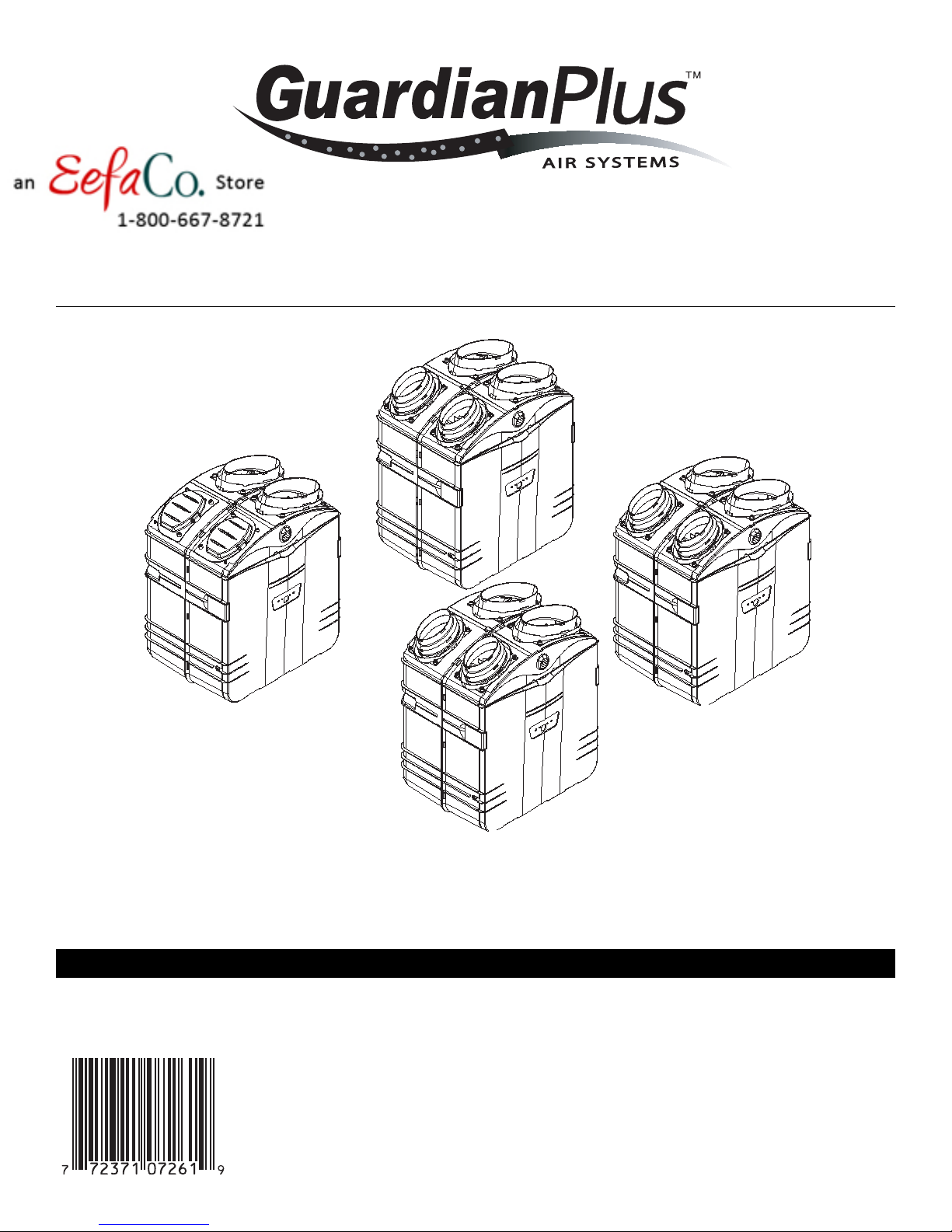
INSTALLATION INSTRUCTIONS MANUAL
HEPA Filtration
and Fresh Air
Ventilation*
GSVH1K
HEPA Filtration,
VB0061
*Patents pending
HEPA
Filtration*
GSFH1K
HEPA Filtration,
Fresh Air and
Energy Recovery
Ventilation*
GSEH3K
Fresh Air and
Heat Recovery
Ventilation*
GSHH3K
INSTALLER: LEAVE THIS MANUAL WITH CONSUMER.
RESIDENTIAL USE ONLY
www.guardianplusairsystems.com
www.Broan-NuTone.com
04326 rev 3
Page 2
ABOUT THIS MANUAL
Congratulation! Your purchase of this whole-house HEPA filtration, with optional ventilation will allow you and your family to enjoy clean
and healthy air throughout your home for years to come!
Please read this manual thoroughly.
Several models are described in this publication. Some details of your unit may be slightly different than the ones shown, as the illustration
are typical ones.
Please take note that this manual uses the following symbols to emphasize particular information:
!
WARNING
Identifies an instruction which, if not followed, might cause serious personal injuries including possibility of death.
CAUTION
Denotes an instruction which, if not followed, may severely damage the unit and/or its components.
NOTE: Indicates supplementary information needed to fully complete an instruction.
We welcome any suggestions you may have concerning this manual and/or the product, or ways to better serve you. Please forward all
correspondence at the address below:
Broan-NuTone LLC
Indoor Air Quality Marketing
926 W. State St.,
Hartford, WI 53027
1-800-558-1711
ABOUT THESE UNITS
!
WARNING
TO REDUCE THE RISK OF FIRE, ELECTRIC SHOCK, OR INJURY TO PERSON(S) OBSERVE THE FOLLOWING:
1. This unit is intented for residential installation only.
2. Installation must be done in accordance with all applicable codes and standards, including fire-rated construction codes
and standards.
3. This unit is not designed to provide combustion and/or dilution air for fuel-burning appliances.
4. Do not install in a cooking area or connect directly to an appliance.
5. Before replacing filters, servicing or cleaning unit, disconnect the power cord from electrical outlet.
6. When cutting or drilling into wall or ceiling, do not damage electrical wiring or other hidden utilities.
7. Do not use this unit with any solid-state speed control device other than wall controls ACCGSC1 or ACCGSC3, provided
with the unit.
8. This unit must be grounded. The power supply cord has a 3-prong grounding plug for your personal safety. It must be
plugged into a mating 3-prong grounding receptacle, grounded in accordance with the national electrical code and local
codes and ordinances. Do not remove the ground prong. Do not use an extension cord.
9. This unit must be installed in a weatherized location out of direct sunlight and protected from the elements.
10. Use this unit only in the manner intended by the manufacturer. If you have questions, contact the manufacturer at the
address or telephone number listed in this document.
1. For general filtration and ventilation use only. Do not use to exhaust hazardous or explosive materials and vapors.
2. Intended for residential installation only in accordance with the requirements of NFPA 90B.
3. For GSVH1K, GSHH3K and GSEH3K units only: Be sure to duct air outside. - Do not intake / exhaust air into spaces with
in walls or ceiling or into attics, crawl spaces, or garage.
4. Do not run any air ducts directly above or closer than 2 ft (0.61 m) to any furnace or its supply plenum, boiler, or other heat
producing appliance. If a duct has to be connected to the furnace return plenum, it must be connected not closer than 2 ft
(0.61 m) from this plenum connection to the furnace.
5. The ductwork is intended to be installed in compliance with all local and national codes that are applicable.
6. To avoid prematurate clogged filters, turn OFF the unit during construction or renovation.
7. Please read the unit specification label on the product for further information and requirements.
NOTE: The energy recovery ventilator GSEH3K is designed to assist in the management of humidity introduced into the home.
In extreme humidity conditions, the use of additional dehumidification may be desirable. Quickly remove all excess moisture and
keep areas clean.
CAUTION
- 2 -
Page 3

TABLE OF CONTENTS
1. BEFORE STARTING . . . . . . . . . . . . . . . . . . . . . . . . . . . . . . . . . . . . . . . . . . . . . . . . . . . . . . . . .4
1.1 INSPECT THE CONTENT OF THE BOX . . . . . . . . . . . . . . . . . . . . . . . . . . . . . . . . . . . . . . . . . . . . . . . . . . . . . . . . .4
2. TECHNICAL DATA . . . . . . . . . . . . . . . . . . . . . . . . . . . . . . . . . . . . . . . . . . . . . . . . . . . . . . . . . .4
2.1 DIMENSIONS AND AIR DISTRIBUTION PORTS . . . . . . . . . . . . . . . . . . . . . . . . . . . . . . . . . . . . . . . . . . . . . . . . . . .5
2.2 VENTILATION PERFORMANCES . . . . . . . . . . . . . . . . . . . . . . . . . . . . . . . . . . . . . . . . . . . . . . . . . . . . . . . . . . . .5-6
2.3 MOUNTING AND SERVICING CONSIDERATIONS . . . . . . . . . . . . . . . . . . . . . . . . . . . . . . . . . . . . . . . . . . . . . . . . . .6
3. RECOVERY NEEDS ACCORDING TO GEOGRAPHICAL LOCATION . . . . . . . . . . . . . . . . . . . . . . . . .7
4. PLANNING THE INSTALLATION . . . . . . . . . . . . . . . . . . . . . . . . . . . . . . . . . . . . . . . . . . . . . . . .7
4.1 PLANNING OF THE DUCTWORK . . . . . . . . . . . . . . . . . . . . . . . . . . . . . . . . . . . . . . . . . . . . . . . . . . . . . . . . . . . . .8
5. TYPICAL INSTALLATIONS . . . . . . . . . . . . . . . . . . . . . . . . . . . . . . . . . . . . . . . . . . . . . . . . . . . . .8
5.1 GSFH1K UNIT INSTALLATIONS . . . . . . . . . . . . . . . . . . . . . . . . . . . . . . . . . . . . . . . . . . . . . . . . . . . . . . . . . . . . .9
5.2 GSVH1K, GSHH3K AND GSEH3K UNITS INSTALLATIONS . . . . . . . . . . . . . . . . . . . . . . . . . . . . . . . . . . . . . . .10
5.3 STAND ALONE INSTALLATION . . . . . . . . . . . . . . . . . . . . . . . . . . . . . . . . . . . . . . . . . . . . . . . . . . . . . . . . . . .11-12
5.4 CENTRAL DRAW POINT INSTALLATION . . . . . . . . . . . . . . . . . . . . . . . . . . . . . . . . . . . . . . . . . . . . . . . . . . . . . . .12
5.5 RETURN-TO-RETURN INSTALLATION . . . . . . . . . . . . . . . . . . . . . . . . . . . . . . . . . . . . . . . . . . . . . . . . . . . . . . . . .13
6. INSTALL THE UNIT . . . . . . . . . . . . . . . . . . . . . . . . . . . . . . . . . . . . . . . . . . . . . . . . . . . . . . . .14
6.1 TOOLS AND MATERIALS . . . . . . . . . . . . . . . . . . . . . . . . . . . . . . . . . . . . . . . . . . . . . . . . . . . . . . . . . . . . . . . . .14
6.2 MOUNT THE PORTS ON THE UNIT . . . . . . . . . . . . . . . . . . . . . . . . . . . . . . . . . . . . . . . . . . . . . . . . . . . . . . . . . .14
6.3 INSTALLATION USING ISOLATOR PADS . . . . . . . . . . . . . . . . . . . . . . . . . . . . . . . . . . . . . . . . . . . . . . . . . . . . . . .14
6.4 FOR SUSPENDED APPLICATIONS . . . . . . . . . . . . . . . . . . . . . . . . . . . . . . . . . . . . . . . . . . . . . . . . . . . . . . . . 15-16
6.5 INSTALLING 8“ DUCTS AND REGISTERS . . . . . . . . . . . . . . . . . . . . . . . . . . . . . . . . . . . . . . . . . . . . . . . . . . .16-19
6.6 INSTALLING INSULATED FLEXIBLE DUCTS TO TANDEM®TRANSITION . . . . . . . . . . . . . . . . . . . . . . . . . . . . . . . . . . 19
6.7 INSTALLING AIRDUO™EXTERIOR HOOD . . . . . . . . . . . . . . . . . . . . . . . . . . . . . . . . . . . . . . . . . . . . . . . . . . 20-21
6.8 INSTALLING TWO EXTERIOR HOODS . . . . . . . . . . . . . . . . . . . . . . . . . . . . . . . . . . . . . . . . . . . . . . . . . . . . . 21-23
6.9 INSTALLING TWO BREIDERT CAPS . . . . . . . . . . . . . . . . . . . . . . . . . . . . . . . . . . . . . . . . . . . . . . . . . . . . . . . 23-24
6.10 CONNECTION TO THE 5’’ TO 6’’ OVAL PORTS OF THE UNIT . . . . . . . . . . . . . . . . . . . . . . . . . . . . . . . . . . . . . . 24-25
6.11 CONNECTING THE DRAIN . . . . . . . . . . . . . . . . . . . . . . . . . . . . . . . . . . . . . . . . . . . . . . . . . . . . . . . . . . . . . . . 25
6.12 LOW TEMPERATURE APPLICATIONS BELOW FREEZING (32°F OR 0°C) . . . . . . . . . . . . . . . . . . . . . . . . . . . . . 26-27
7. CONTROLS . . . . . . . . . . . . . . . . . . . . . . . . . . . . . . . . . . . . . . . . . . . . . . . . . . . . . . . . . . . . .27
7.1 MAIN SWITCH . . . . . . . . . . . . . . . . . . . . . . . . . . . . . . . . . . . . . . . . . . . . . . . . . . . . . . . . . . . . . . . . . . . . . . . 27
7.2 WALL CONTROLLERS . . . . . . . . . . . . . . . . . . . . . . . . . . . . . . . . . . . . . . . . . . . . . . . . . . . . . . . . . . . . . . . . . 27
7.3 DIMENSIONS . . . . . . . . . . . . . . . . . . . . . . . . . . . . . . . . . . . . . . . . . . . . . . . . . . . . . . . . . . . . . . . . . . . . . . . . 28
7.4 INSTALLATION OF THE WALL CONTROLLERS . . . . . . . . . . . . . . . . . . . . . . . . . . . . . . . . . . . . . . . . . . . . . . . . 28-30
7.5 OPERATING ACCGSC1 CONTROLLER . . . . . . . . . . . . . . . . . . . . . . . . . . . . . . . . . . . . . . . . . . . . . . . . . . . . . . 30
7.6 OPERATING ACCGSC3 CONTROLLER . . . . . . . . . . . . . . . . . . . . . . . . . . . . . . . . . . . . . . . . . . . . . . . . . . . . . . 31
8. BALANCING PROCEDURE . . . . . . . . . . . . . . . . . . . . . . . . . . . . . . . . . . . . . . . . . . . . . . . . . . .32
8.1 WHAT YOU NEED TO BALANCE THE UNIT . . . . . . . . . . . . . . . . . . . . . . . . . . . . . . . . . . . . . . . . . . . . . . . . . . . . .32
8.2 PRELIMINARY STAGES FOR BALANCING THE UNIT . . . . . . . . . . . . . . . . . . . . . . . . . . . . . . . . . . . . . . . . . . . . . . .32
8.3 INSTALLATION OF FLOW COLLAR . . . . . . . . . . . . . . . . . . . . . . . . . . . . . . . . . . . . . . . . . . . . . . . . . . . . . . . . . . .32
8.4 BALANCING PROCEDURE . . . . . . . . . . . . . . . . . . . . . . . . . . . . . . . . . . . . . . . . . . . . . . . . . . . . . . . . . . . . . . . .32
9. MAINTENANCE . . . . . . . . . . . . . . . . . . . . . . . . . . . . . . . . . . . . . . . . . . . . . . . . . . . . . . . . . . .33
9.1 SEMI-ANNUAL MAINTENANCE (ESSENTIAL) . . . . . . . . . . . . . . . . . . . . . . . . . . . . . . . . . . . . . . . . . . . . . . . . .33-34
9.2 ANNUAL MAINTENANCE . . . . . . . . . . . . . . . . . . . . . . . . . . . . . . . . . . . . . . . . . . . . . . . . . . . . . . . . . . . . . . . . .35
9.3 MASTER RESET . . . . . . . . . . . . . . . . . . . . . . . . . . . . . . . . . . . . . . . . . . . . . . . . . . . . . . . . . . . . . . . . . . . . . .35
9.4 O
PTIONAL ALPINE/PINE FILTER . . . . . . . . . . . . . . . . . . . . . . . . . . . . . . . . . . . . . . . . . . . . . . . . . . . . . . . . . . . .35
10. TROUBLESHOOTING . . . . . . . . . . . . . . . . . . . . . . . . . . . . . . . . . . . . . . . . . . . . . . . . . . . . . . .36
11. W
ARRANTY . . . . . . . . . . . . . . . . . . . . . . . . . . . . . . . . . . . . . . . . . . . . . . . . . . . . . . . . . . . . .36
- 3 -
Page 4
1. BEFORE STARTING
1.1 INSPECT THE CONTENTS OF THE BOX
!
WARNING
To avoid risk of suffocation, discard the plastic bag wrapping the unit.
• Inspect the exterior of the unit for shipping damage. Ensure there is no damage to the door, door latches, main switch, etc.
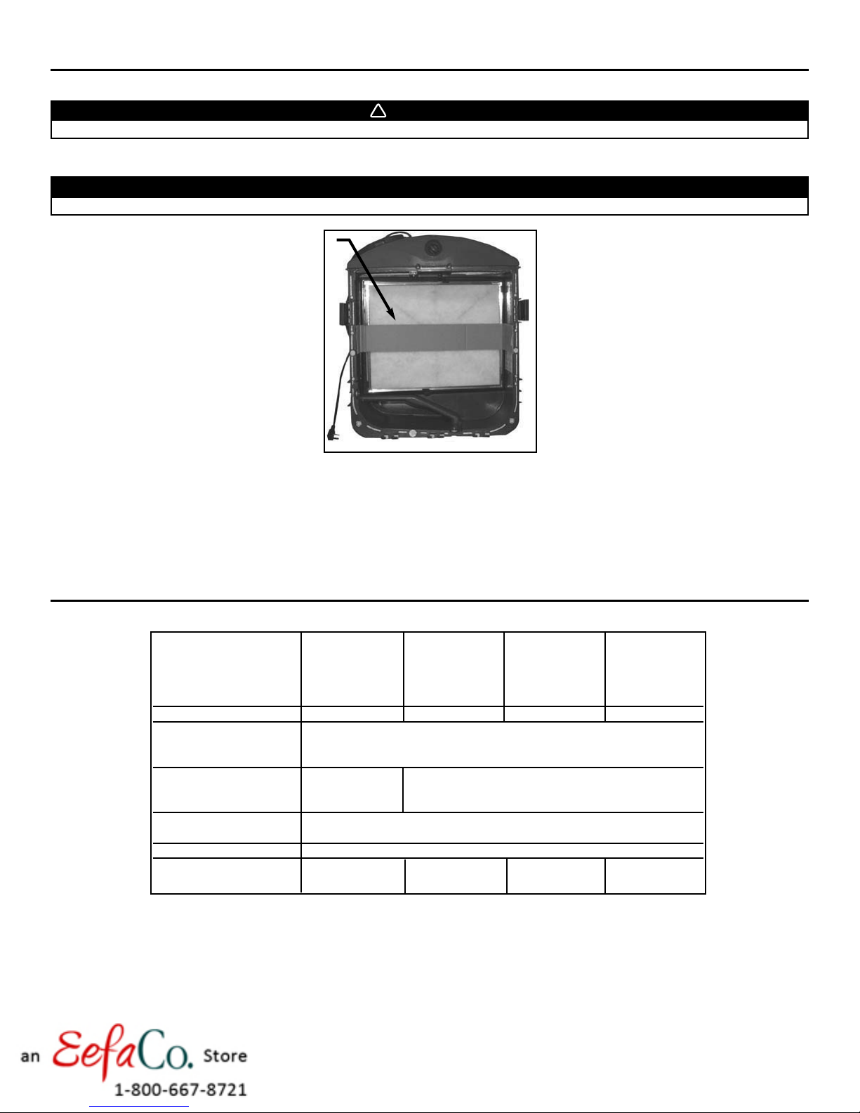
CAUTION
Remove the cardboard strip inside the unit (if applicable).
1
VD0126
1) Cardboard strip
• Inspect the interior of the unit for damage. Ensure the blower assembly, heat recovery core (model GSHH3K), energy recovery core
(model GSEH3K), insulation, dampers (models GSVH1K , GSHH3K and GSEH3K), prefilter, HEPA filter, etc. are all intact.
• If the unit was damaged during shipping, contact your local distributor, or Broan-NuTone at 1-800-558-1711.
2. TECHNICAL DATA
GSFH1K GSVH1K GSHH3K GSEH3K
HEPA Filtration HEPA Filtration, HEPA Filtration,
Models HEPA Filtration & Fresh Air Fresh Air & Fresh Air &
Ventilation Heat Recovery Energy Recovery
Ventilation Ventilation
Weight 34 lbs (15.4 kg) 36 lbs (16.3 kg) 40 lbs (18.2 kg) 40 lbs (18.2 kg)
Oval shaped duct collars
for non-insulated ducts fits two 8” round ducts
to inside
Oval shaped duct collars
for insulated ducts N/A fits two 5” or 6” round ducts
to outside
Installation: Suspended Chains, springs and hooks (provided with the unit)
or rest on a shelf or floor: or 4 pads (provided with the unit)
Electrical Supply 120 Volts AC, 60 Hz
Power Consum. (Boost) 170 Watts 224 Watts 229 Watts 224 Watts
Power Consum. (Normal) 132 Watts 152 Watts 170 Watts 170 Watts
NOTE: Due to our ongoing commitment to product quality and innovation, all specifications are subjected to change without notice.
- 4 -
Page 5
2. TECHNICAL DATA (CONT’D)
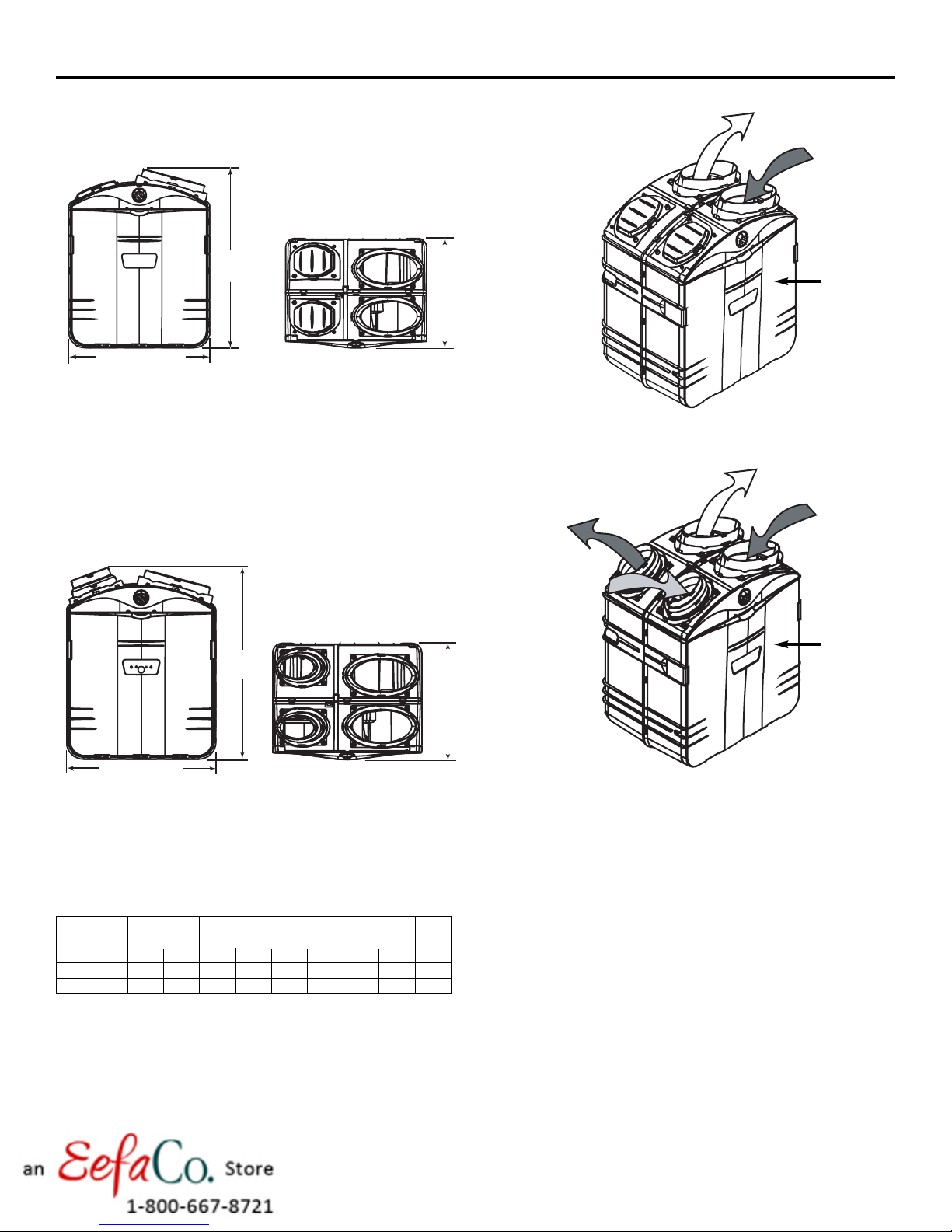
2.1 DIMENSIONS AND AIR DISTRIBUTION PORTS
HEPA FILTRATION UNIT, MODEL GSFH1K
29''
(737 mm)
22.9'' (581 mm)
VK0047
FILTERED AIR
TO BUILDING
STALE AIR
FROM
BUILDING
FRONT
17.8''
(452 mm
FRONT VIEW TOP VIEW
HEPA FILTRATION UNIT AND FRESH AIR VENTILATION,
MODEL GSVH1K
HEPA FILTRATION, FRESH AIR AND HEAT RECOVERY
VENTILATION, MODEL GSHH3K
HEPA FILTRATION, FRESH AIR AND ENERGY RECOVERY
VENTILATION, MODEL GSEH3K
29.4''
(748 mm)
17.8''
(452 mm)
22.9'' (581 mm)
VK0048
FRONT VIEW TOP VIEW
2.2 VENTILATION PERFORMANCES
2.2.1 GSVH1K VENTILATION PERFORMANCES
STALE AIR
TO
OUTSIDE
FRESH
AIR FROM
OUTSIDE
VF0033
FRESH AND FILTERED
AIR TO BUILDING
STALE AIR
FROM
BUILDING
FRONT
VF0029
EXT STATIC NET VENTILATION GROSS AIR FLOW
PRESSURE AIRFLOW SUPPLY EXHAUST FILTERED
Pa
in.w.g.
l/s
cfm
l/s
cfm
l/s
cfm
50
0.2
52
110
56
118
54
115
100
0.4
49
104
52
111
49
104
NOTE: all tests performed at high speed.
132
121
POWER
l/s
cfm
Watts
279
231
257
224
- 5 -
Page 6
2. TECHNICAL DATA (CONT’D)
2.2 VENTILATION PERFORMANCES (CONT’D)
2.2.2 GSHH3K V
ENTILATION PERFORMANCES 2.2.3 GSEH3K VENTILATION PERFORMANCES
EXT STATIC NET VENTILATION GROSS AIR FLOW
PRESSURE AIRFLOW SUPPLY EXHAUST FILTERED
Pa
in.w.g.
l/s
cfm
l/s
cfm
l/s
cfm
l/s
50
0.2
52
110
58
124
57
121
131
100
0.4
49
103
55
116
51
108
119
cfm
277
252
POWER
Watts
237
229
EXT STATIC NET VENTILATION GROSS AIR FLOW
PRESSURE AIRFLOW SUPPLY EXHAUST FILTERED
Pa
in.w.g.
l/s
cfm
50
0.2
57
122
100
0.4
53
113
NOTE: all tests performed at high speed.
2.3 MOUNTING AND SERVICING CONSIDERATIONS
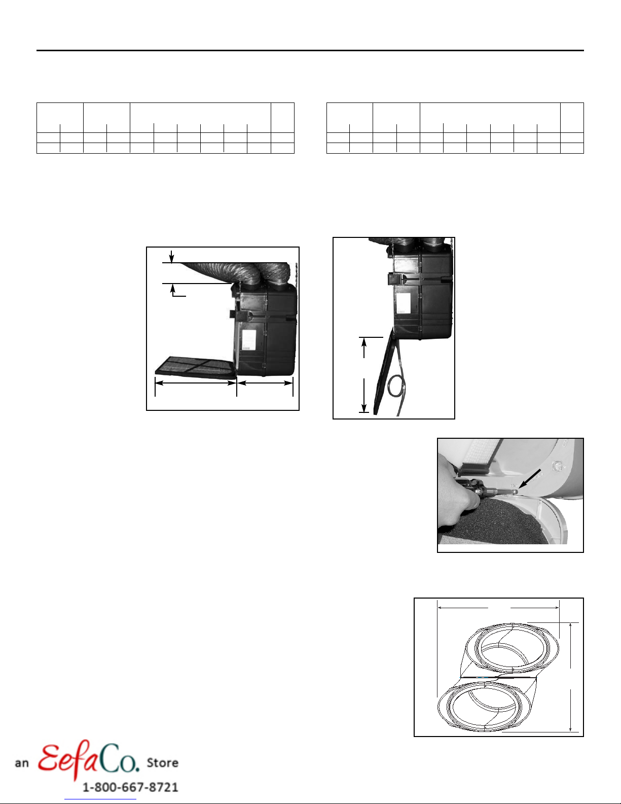
• The two following pictures are showing the minimum clearance needed to open the door completely.
8”
(203 mm)
22”
(559 mm)
22.5” 15.75”
(572 mm) (400 mm)
VD0117
VD0116
l/s
50
48
cfm
105
102
POWER
l/s
cfm
l/s
cfm
Watts
59
125
127
270
227
55
117
120
254
224
NOTES: 1. The unit door is removable. To do so, remove the stopper (A) located on the
right side of the door hinge, then, slide the door out of its hinge. For servicing, a minimum
of 15’’ (381 mm) clearance from any obstruction in front of the unit is sufficient to open
the door and remove it.
2. A minimum of 8” (203 mm) clearance from any obstruction on top of the unit is required
for the ductwork radius turn.
• The joist opening needed to install the Tandem®transition must be 9 3/4” (248 mm)
minimum. Also, the maximum height of the Tandem®transition is 8 3/4” (222 mm).
See Tandem®transition end view beside.
NOTES: 1. If there is not enough space to use the Tandem®transition, the optional exterior
single hood must be installed to bring the fresh outside air to the unit.
See Section 6.8.
2. When installing a HEPA Filtration model GSFH1K, there is no Tandem®transition.
VD0118
VD0170
9 3/4"
248 mm
A
8 3/4"
222 mm
- 6 -
Page 7

3. RECOVERY NEEDS ACCORDING TO GEOGRAPHICAL LOCATION
N
When recovery is important, it can be hard to find the appropriate unit. Use the map below to determine which between heat
recovery (GSHH3K model) or energy recovery (GSEH3K model) will satisfy the specific needs of the consumers.
OLYMPIA
SALEM
BOISE
RENO
SACRAMENTO
HELENA
SALT LAKE CITY
PHOENIX
ZONE A
DENVER
SANTA FE
BISMARCK
A
TOPEK
OKLAHOMA CITY
ST. PAUL
MADISON
DES MOINES
SPRINGFIELD
DETROIT
INDIANAPOLIS
NASHVILLE
ATLANTA
HARRISBURG
COLUMBUS
COLUMBIA
BOSTO
HARTFORD
WASHINGTON
RALEIGH
ZONE B
When exchanging air with outside:
AUSTIN
BATON ROUGE
ZONE A: GSHH3K unit recommended*
ZONE B: GSEH3K unit recommended
* In ZONE A, the GSEH3K unit may be used, but below 16°F,
the duration of exchanging air with outside will decrease.
VN0004A
4. PLANNING THE INSTALLATION
The Guardian Plus units are versatile appliances capable of delivering filtered air (model GSFH1K) or both filtered and fresh air to
your home (models GSVH1K, GSHH3K and GSEH3K). Because each installation is different, it is recommended you take the time to
plan your installation. The three main areas to plan for are:
• Where to locate the GuardianPlus unit
• How to pick-up the air from the room and distribute the filtered or fresh/filtered air
• Where to bring fresh air from outside and exhaust stale air to outside (models GSVH1K, GSHH3K and GSEH3K).
Use the following chart to determine the appropriate installation method for the unit.
Is the house equipped with a furnace or air handler?
YES
Is there enough space to connect the unit duct(s) to the existing
furnace or air handler ductwork? (The unit duct connection can be
performed on the cold air return duct or supply air duct, at a minimum
linear distance of 2’ (0.61 m) from the furnace/air handler.)
NO
Use Stand Alone installation.
See Section 5.3.
NO
YES
The Central Draw Point
installation can be performed.
Example: Basement installation
in Section 5.4.1
OR
The Return-to-Return
installation can be performed.
Example: Crawl space installation
in Section 5.5.1
CAUTION
Do not install duct or duct connector directly above the furnace. Do not connect the plenum connection closer than 2’ (0.61m)
to the furnace, as measured along the length of the duct.
- 7 -
Page 8
4. PLANNING THE INSTALLATION (CONT’D)
4
.1 PLANNING OF THE DUCTWORK
• Keep it simple. Plan for a minimum of bends and joints.
• Keep the length of insulated ducts to the outside of home to a minimum.(not for HEPA Filtration model GSFH1K).
• Do not ventilate crawl spaces or cold rooms.
• If the house has two floors or more, be sure to plan for at least one exhaust register on the highest lived-in level.
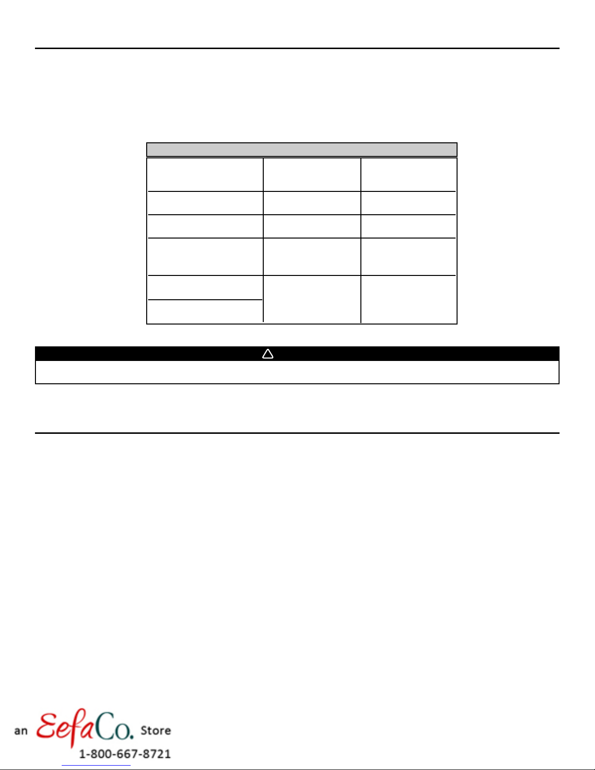
Use the table below to plan the flexible ducts length.
FLEXIBLE DUCT LENGTH TABLE
Maximum Maximum
recommended length recommended length
to reach 105 cfm to reach 95 cfm
Insulated fresh air duct
from outside (6” diameter)
Insulated exhaust air duct
to outside (6” diameter)
Stale air duct from inside
(8” diameter) Combined: 40’ Combined: 60’ with
Filtered air duct to inside stale air duct not to
(8” diameter) exceed 36’
up to 10’ from 10’ to 20’
up to 10’ from 10’ to 20’
Recommended Recommended
maximum length maximum length
to reach 270 cfm to reach 240 cfm
!
WARNING
Do not attempt to recover in any ways the exhaust air from a dryer or a range hood. This would cause clogging of the filters
and recovery module (if applicable); this is also a fire hazard. Not following this warning will void the warranty.
5. TYPICAL INSTALLATIONS
Installations may vary according to the model number, the product orientation (vertical or horizontal) and the location in the home where
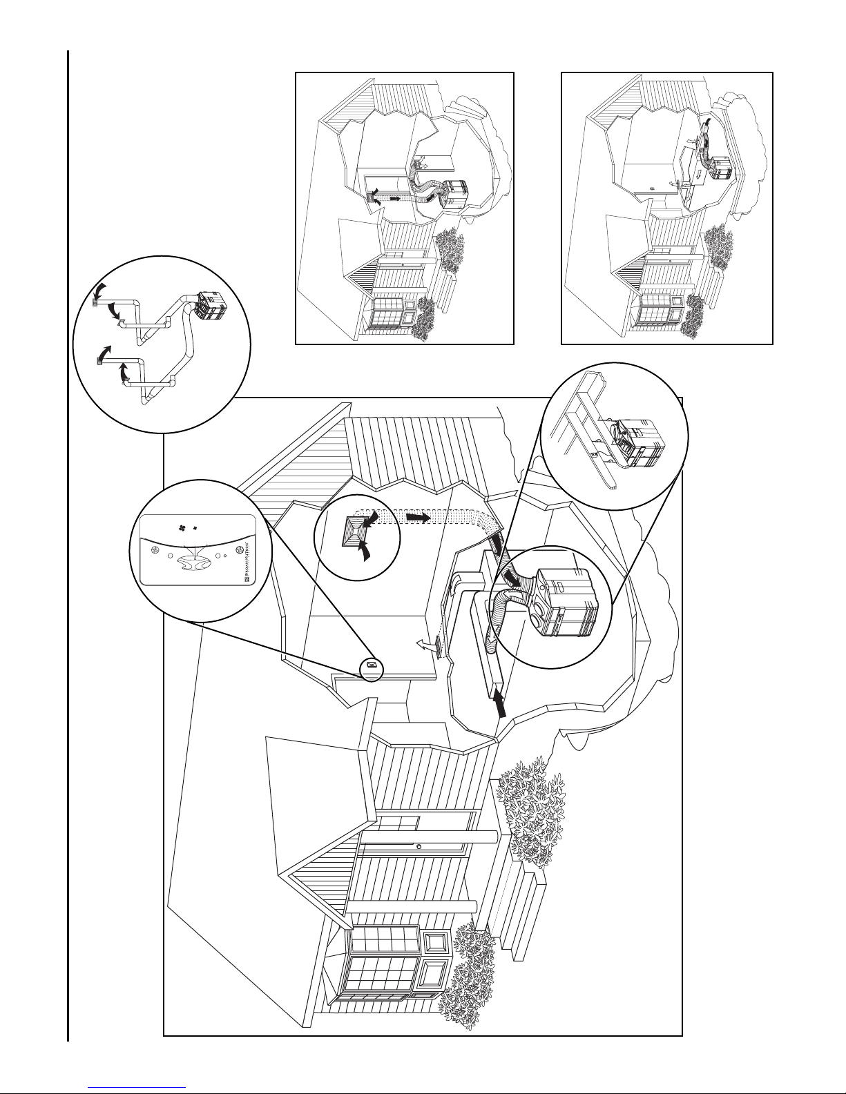
the unit is installed. Use the following illustrations as guidelines to help you decide the appropriate installation.
The unit allows for multi positional mounting (vertical or horizontal). It may be hung to the joists (preferred method),or it may be laid down
on one of three surfaces, and installed either vertically or horizontally.
NOTE: For more details, see Points 5.3 and 5.4 in Section 5 INSTALL THE UNIT.
In every case, bathroom fans and a range hood should be used as spot ventilation to exhaust stale air. Also, for homes with more than
one level, we recommend placing one exhaust register at the highest lived-in level.
There are threer installation methods: Stand Alone, Central Draw Point* and Return-to-Return*.
* Different connections to a forced air system.
Multiple furnaces or air handlers may require installation of GuardianPlus on each system for maximum IAQ benefit.
NOTE: A grounded three-prong electrical outlet has to be available within 3 feet from the unit.
- 8 -
Page 9
INSTALLING 8’’ DUCTS AND
VD0129
VC0059
High
Low
OFF
Reset Filter
Filter Maintenance
Power
VI0013
REGISTERS
SEE SECTIONS 6.5
SECTION 7: CONTROLS
STAND ALONE INSTALLATION
SEE SECTION 5.3.1
VH0037
RETURN-TO-RETURN INSTALLATION
SEE SECTION 5.5.1
VH0047
SEE SECTION 6.4
HOW TO HANG THE UNIT
NOTE:OTHER INSTALLATIONS SHOWN NEXT PAGES
INSTALLATION TYPE SHOWN:CENTRAL DRAW POINT
5.1. GSFH1K UNIT INSTALLATION
SEE SECTION 5.4.1
VH0038
- 9 -
Page 10

VD0150
VO0029
Off
Recirculation
Reset Filter
Filter Maintenance
Fresh air
High Ventilation
Low Ventilation
VC0060
INSTALLING 8’’ DUCTS AND
VI0011
REGISTERS
SEE SECTIONS 6.5
STAND ALONE INSTALLATION
SEE SECTION 5.3.1
RETURN-TO-RETURN INSTALLATION
SEE SECTION 5.5.1
SECTION 7: CONTROL
VH0039
HOW TO HANG THE UNIT
SEE SECTION 6.4
VH0043
CONNECTING THE DRAIN
NEXT PAGES
NOTE:OTHER INSTALLATIONS SHOWN
SEE SECTION 6.11
5.2. GSVH1K, GSHH3K AND GSEH3K UNITS INSTALLATION
INSTALLATION TYPE SHOWN:CENTRAL DRAW POINT
SEE SECTION 5.4.1
- 10 -
VH0040
OUTDOOR CONNECTION
SEE SECTIONS 6.7, 6.8 AND 6.9
Page 11
5. TYPICAL INSTALLATIONS (CONT’D)
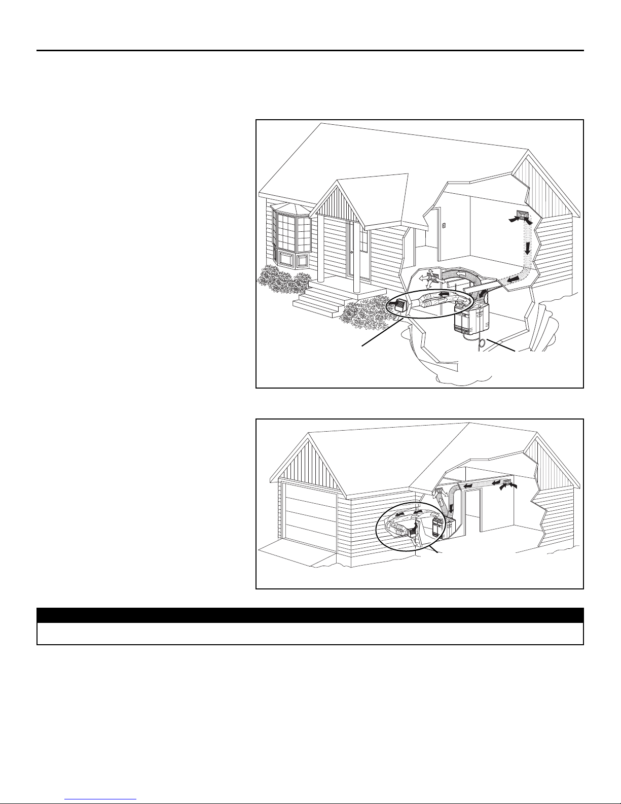
5.3 STAND ALONE INSTALLATION
(Primarily for homes with no central air mover or equipped with wall furnaces, radiant hot water or electric baseboard heating.)
5.3.1 BASEMENT
• Ideal for homes without a central
furnace in the basement. Allows
filtration and a better air circulation
throughout the house.
• Easy access to perform the periodic
filter maintenance and servicing.
• Offers an ambient temperature
above freezing (32°F - 0°C).
• The HEPA Filtration model GSFH1K
has no connection to the outside,
so all parts encircled are not required.
INSTALLATION CONSIDERATIONS:
• Installing the unit near an exterior
wall will shorten the length of the
insulated ducts (not necessary for
HEPA Filtration only model GSFH1K).
• If a HEPA Filtration Fresh Air &
Heat Recovery Ventilation model
GSHH3K is installed, a water drain
must be close to collect the run-off.
Only for the models GSVH1K,
GSHH3K and GSEH3K that
use fresh outside air.
VH0039
Drain required only for the
GSHH3K model.
5.3.2 GARAGE CLOSET
• Ideal for homes without a central
furnace, or limited space applications,
allows filtration and a better air
circulation throughout the house.
• Easy access to perform the periodic
maintenance (twice a year).
• The HEPA Filtration model GSFH1K
has no connection to outside, so all
parts encircled are not required.
Only for the models GSVH1K,
VH0046
GSHH3K and GSEH3K that
use fresh outside air.
CAUTION
When the ambient temperature for the unit location is below freezing (32°F - 0°C), the unit must run continuously to prevent
condensation.
INSTALLATION CONSIDERATIONS:
• Installing the unit near an exterior wall will shorten the length of the insulated ducts
(not necessary for HEPA Filtration model GSFH1K).
• If a HEPA Filtration Fresh Air & Heat Recovery Ventilation model GSHH3K is installed, a water drain must be close to collect
the run-off.
• All ducts must be insulated.
• For the HEPA Filtration, Fresh Air & Heat Recovery Ventilation (GSHH3K) and the HEPA Filtration, Fresh Air & Energy
Recovery Ventilation (GSEH3K) models only, if the ambient temperature around the unit drops below freezing (32°F - 0°C),
go to Section 6.12 (Low Temperature Applications) for instructions on drain line protection (GSHH3K only) and other cold
environment installation details.
- 11 -
Page 12
5. TYPICAL INSTALLATIONS (CONT’D)
5.3 STAND ALONE INSTALLATION (CONT’D)
(Primarily for homes with no central air mover or equipped with wall furnaces, radiant hot water or electric baseboard heating.)
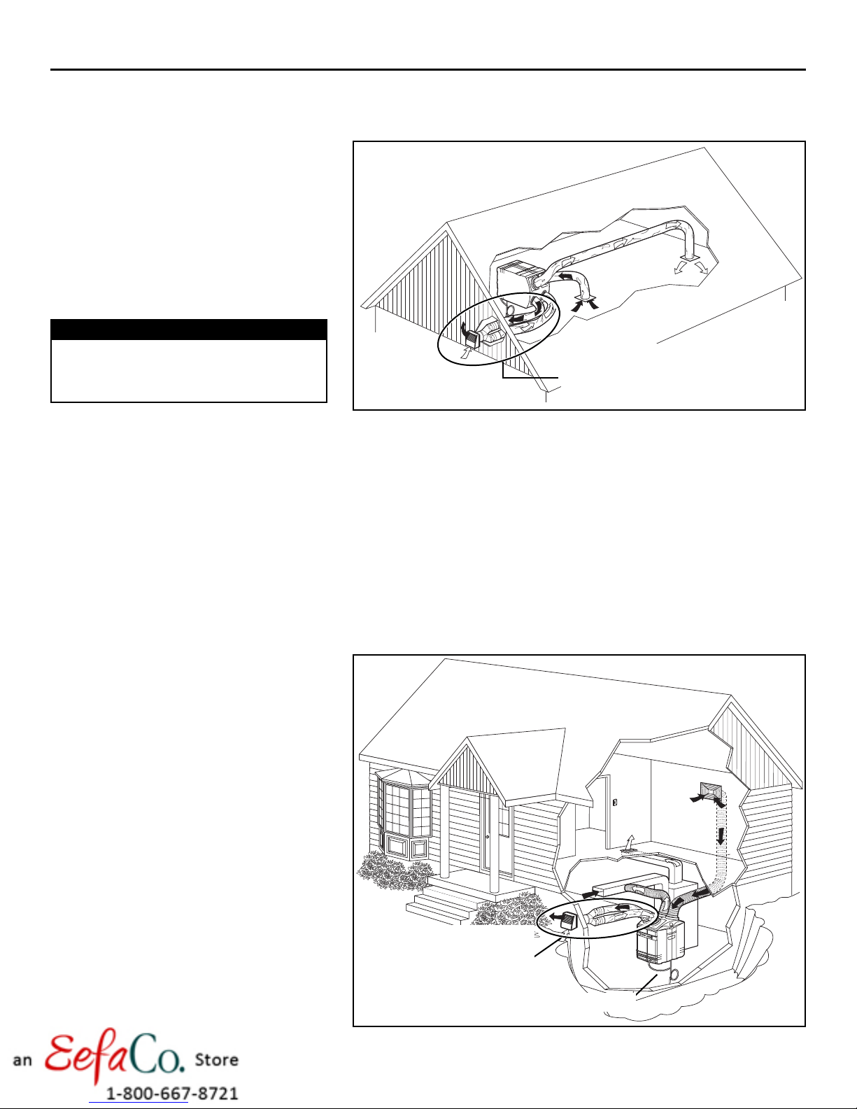
5.3.3 ATTIC
• Ideal for homes without a central
furnace, or limited space applications,
allows filtration and a better air
circulation throughout the house.
• Only one partition to go through to
install the registers.
• No visible ducts.
• The HEPA Filtration model GSFH1K
has no connection to the outside,
so all parts encircled are not required.
CAUTION
When the ambient temperature for the unit
location is below freezing (32°F - 0°C), the
unit must run continuously to prevent
condensation.
INSTALLATION CONSIDERATIONS:
• Installing the unit near an exterior wall will shorten the length of the insulated ducts
(not necessary for HEPA Filtration only model GSFH1K).
• If a HEPA Filtration Fresh Air & Heat Recovery Ventilation model GSHH3K is installed, a water drain must be close to collect
the run-off.
• All ducts must be insulated.
• For the HEPA Filtration, Fresh Air & Heat Recovery Ventilation (GSHH3K) and the HEPA Filtration, Fresh Air & Energy
Recovery Ventilation (GSEH3K) models only, if the ambient temperature around the unit drops below freezing (32°F - 0°C),
go to Section 6.12 (Low Temperature Applications) for instructions on drain line protection (GSHH3K only) and other cold
environment installation details.
VH0054
Only for the models GSVH1K, GSHH3K
and GSEH3K that use fresh outside air.
Drain required only for the GSHH3K
model .
5.4 CENTRAL DRAW POINT INSTALLATION
(Connection to a Forced Air System)
5.4.1 BASEMENT
• Simplified installation by using the
home existing ductwork to supply
filtered air throughout the house.
• The central draw point should be
located in the main area where
most of the pollutants are produced.
• The furnace/air handler does not
need to run continuously.
• Easy access to perform the periodic
maintenance (twice a year).
• Offers an ambient temperature
above freezing (32°F - 0°C).
• The HEPA Filtration model GSFH1K
has no connection to outside, so all
parts encircled are not required.
INSTALLATION CONSIDERATIONS:
• Installing the unit near an exterior
wall will shorten the length of the
insulated ducts (not necessary for
HEPA Filtration only model GSFH1K).
• If a HEPA Filtration Fresh Air & Heat
Recovery Ventilation model GSHH3K
is installed, a water drain must be
close to collect the run-off.
Only for the models GSVH1K,
GSHH3K and GSEH3K that
use fresh outside air.
Drain required only for the GSHH3K.
VH0040
- 12 -
Page 13
5. TYPICAL INSTALLATIONS (CONT’D)
5.5 RETURN-TO-RETURN INSTALLATION
(Connection to a Forced Air System)
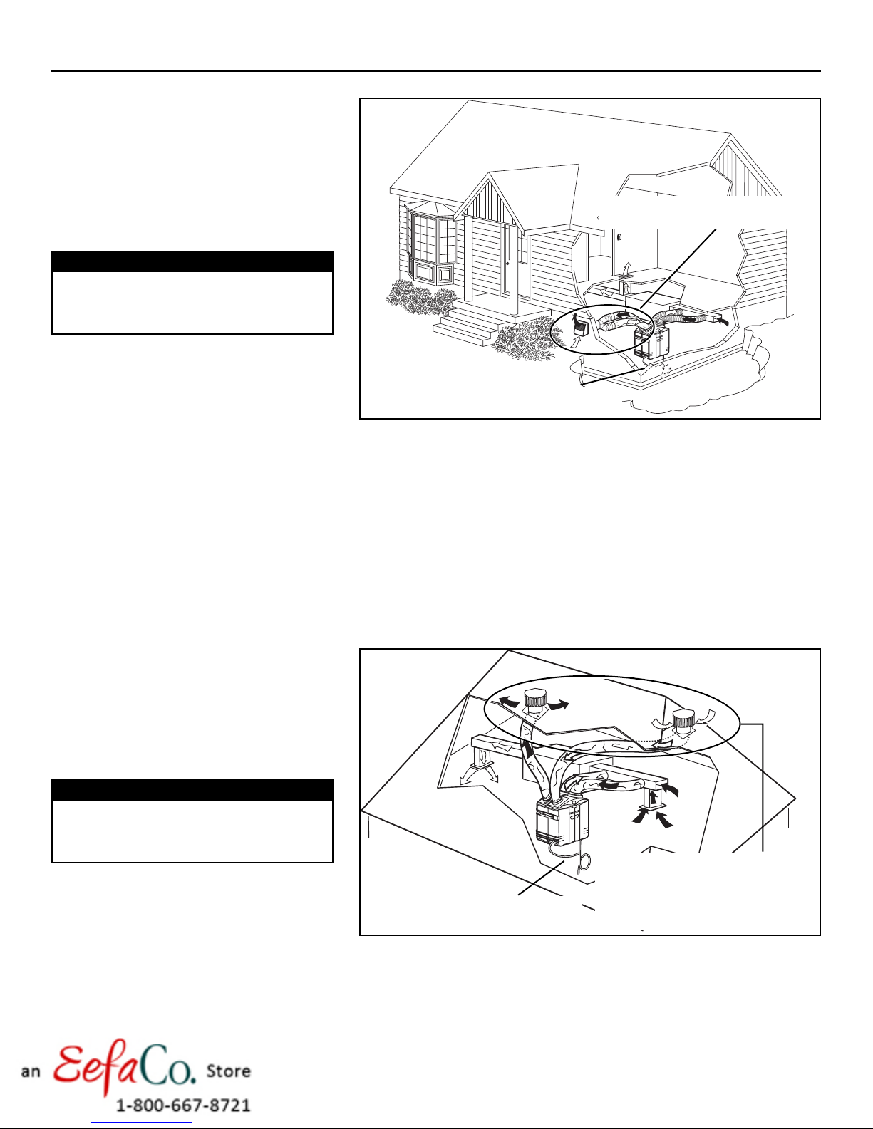
5.5.1 CRAWL SPA C E
• Simplify the installation by using
the existing ductwork.
• Non-visible ducts.
• The HEPA Filtration model GSFH1K
has no connection to outside, so all
parts encircled are not required.
CAUTION
When the ambient temperature for the unit
location is below freezing (32°F - 0°C), the
unit must run continuously to prevent
condensation.
INSTALLATION CONSIDERATIONS:
• Installing the unit near an exterior wall
will shorten the length of the insulated
ducts (not necessary for HEPA Filtration
model GSFH1K).
• If a HEPA Filtration Fresh Air & Heat Recovery Ventilation model GSHH3K is installed, a water drain must be close to collect
the run-off.
• To avoid the cross-contamination and achieve highest efficiencies, the furnace / air handler blower must always be ON (or
the efficiency will be affected).
• The HEPA Filtration Fresh Air Ventilation model GSVH1K needs to be ON all the time, since it doesn’t have motorized
dampers. If this unit is OFF, then the furnace / air handler will draw cold outdoor air inside.
• All ducts must be insulated.
• For the HEPA Filtration, Fresh Air & Heat Recovery Ventilation (GSHH3K) and the HEPA Filtration, Fresh Air & Energy
Recovery Ventilation (GSEH3K) models only, if the ambient temperature around the unit drops below freezing (32°F - 0°C),
go to Section 6.12 (Low Temperature Applications) for instructions on drain line protection (GSHH3K only) and other cold
environment installation details.
Drain required only for the GSHH3K.
VH0043
GSVH1K, GSHH3K and GSEH3K
that use fresh outside air.
5.5.2 ATTIC
• Simplify the installation by using
the existing ductwork.
• Non-visible ducts.
• The HEPA Filtration model GSFH1K
has no connection to outside, so all
parts encircled are not required.
CAUTION
When the ambient temperature for the unit
location is below freezing (32°F - 0°C), the
unit must run continuously to prevent
condensation.
INSTALLATION CONSIDERATIONS:
• If a HEPA Filtration Fresh Air & Heat
Recovery Ventilation model GSHH3K
is installed, a water drain must be
close to collect the run-off.
• All ducts must be insulated.
• For the HEPA Filtration, Fresh Air & Heat Recovery Ventilation (GSHH3K) and the HEPA Filtration, Fresh Air & Energy
Recovery Ventilation (GSEH3K) models only, if the ambient temperature around the unit drops below freezing (32°F - 0°C),
go to Section 6.12 (Low Temperature Applications) for instructions on drain line protection (GSHH3K only) and other cold
environment installation details.
Drain required only for the GSHH3K.
VH0050
Optional Breidert caps (such as
Air-X-Hauster relief ventilator) can be
used to pick up fresh outside air and
evacuate stale air. See Section 6.9
for more installation details.
- 13 -
Page 14
6. INSTALL THE UNIT
6.1 TOOLS AND MATERIALS
Here are the tools and materials needed to perform the installation:
• Phillips screwdriver #2 or Robertson #1
• Hammer and flat blade screwdriver (for plenum connection installation only, to make holes in existing metal duct)
• Scissors or utility knife (to cut duct tape)
• Duct tape
• Tin snips or metal shear (for plenum connection installation only, to cut ductwork)
• Aluminum duct tape (for plenum connection installation only, use SMACNA duct tape)
• Jigsaw (except for the HEPA Filtration model GSFH1K)
• Extension cord
• Caulking gun and caulking (except for the HEPA Filtration model GSFH1K)
• 6’’ Diameter insulated ducting (except for the HEPA Filtration model GSFH1K)
• 8’’ Diameter insulated ducting.
NOTE: A 3-prong grounded 120 volt AC power outlet must exist or be installed within 3 ft of the unit, prior to unit installation.
6.2 MOUNT THE PORTS ON THE UNIT
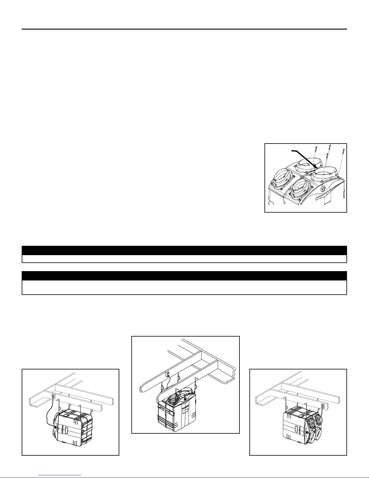
Mount the 8” oval ports and the 5” to 6” oval ports on the top of the unit using the screws provided in
the hardware box (4 screws #8 x 3/4” long per port).
NOTES: 1. Although 4 screws are provided and prefered; only 1 screw per port is required
to meet code.
2. The HEPA Filtration only model has no 5” to 6” oval ports.
3. Do not install the front 8’’ oval port (item 1 in illustration) at this time.
1
VO0018
6.3 INSTALLATION USING ISOLATOR PADS
If the unit cannot be hung, use the four adhesive square isolation pads provided with the unit. According to your needs and model (with
or without drain), you can install the unit either in vertical or horizontal position.
CAUTION
Make sure the unit is level.
CAUTION
When a HEPA Filtration Fresh Air & Heat Recovery Ventilation unit model GSHH3K is installed with adhesive isolator pads,
keep a minimum clearance of 4” between the unit and the ground (or shelf) for the drain.
6.4 FOR SUSPENDED APPLICATIONS
Use the four chains and springs in the hardware pack provided with the unit. According to your needs and model type, you can install the
unit either in a vertical or horizontal position.
VERTICAL POSITION - ALL MODELS
HORIZONTAL POSITION (LEFT SIDE)
LL MODELS
A
HORIZONTAL POSITION (RIGHT SIDE) MODEL
GSFH1K ONLY
VD0075
VD0074
VD0076
- 14 -
Page 15
6. INSTALL THE UNIT (CONT’D)
6.4 FOR SUSPENDED APPLICATIONS (CONT’D)
CAUTION
Make sure the unit is level.
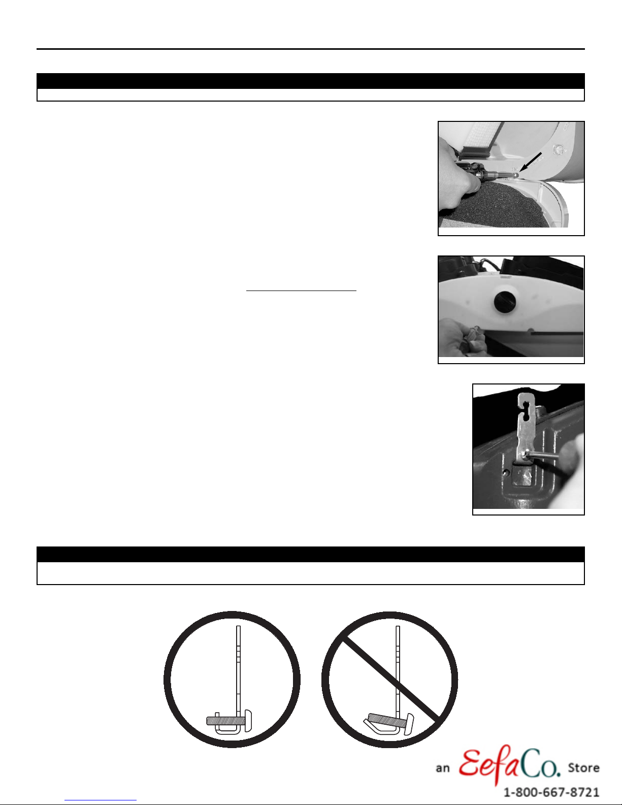
If preferred, the door can be removed. First, remove the stopper (A) located on the right side of the
door hinge, then, slide the door out of its hinge.
• Verify the switch knob is in the OFF position in order to unlock the door. Unlatch the door,
using the 2 latches to open and remove by sliding it out of its hinge. Using a screwdriver,
remove the two retaining screws of the front plate as shown, and carefully remove the front
plate from the unit.
A
VD0170
VO0019
• Insert the four hooks in the square holes and fix them to the unit using four screws #8 - 32 x 3/4”.
VO0020
CAUTION
Take care to insert the screws perpendicular to their hooks, in order to avoid potential damages due to loosen hooks.
See illustrations below.
DO DO NOT
VO0063
- 15 -
Page 16
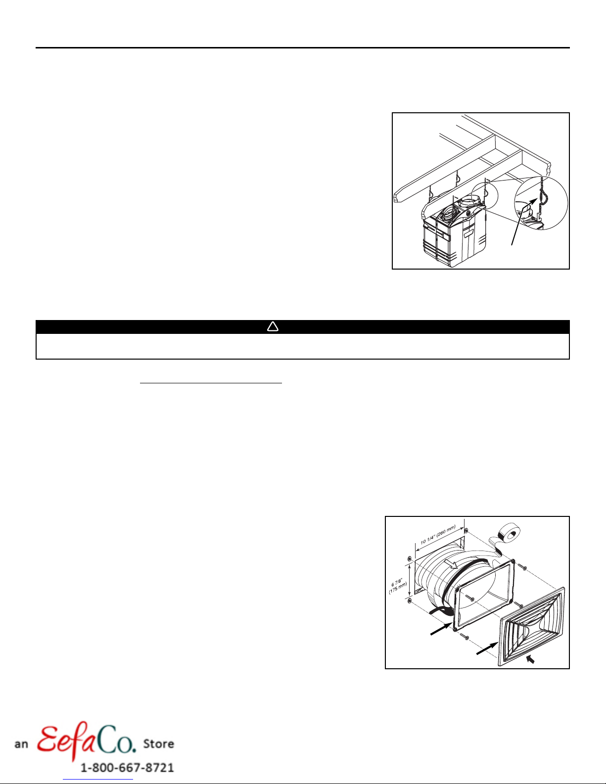
6. INSTALL THE UNIT (CONT’D)
6.4 FOR SUSPENDED APPLICATIONS (CONT’D)
NOTE: To wire the wall control, go to Section 7.4.
• Reinstall the front plate, the door and the door stopper.
• Hang the unit to the joists, using four #8 x 1 1/2” screws, four chains and four spings.
See illustration.
SPRING
VD0077
6.5 INSTALLING 8’’ DUCTS AND REGISTERS
6.5.1 STAND ALONE SYSTEM (AS ILLUSTRATED IN SECTION 5.3)
Stale air collection ductwork
!
WARNING
Never install a stale air exhaust register in a closed room where a combustion device operates, such as a gas furnace, a gas
water heater or dryer, or a fireplace.
• Install the stale air collection register in the main area where the contaminants are produced: kitchen, living room, etc.
Position the register as f
• If the register is installed in the kitchen, it must be located at least 4’ (1.2 m) from the range.
• Install the register 6”-8” (152 to 203 mm) from the ceiling on an interior wall OR install it in the ceiling.
Fresh / Filtered air distribution ductwork
• Install the fresh / filtered air distribution register in a large, open area in the lowest level to ensure the greatest possible air
circulation. Keep in mind the filtered air register must be located as far as possible from the stale air collection point.
• Install the register 6”-8” (152 to 203 mm) from the ceiling on an interior wall OR install it in the ceiling. The duct length should be
at least 15’ (4.6 m). (The fresh / filtered air will then flow through the room and mix with room air, ensuring a continuous
recirculating airflow.)
ar from any stairway as possible and in a way the air circulates all the lived-in spaces in the house.
How to connect the 8’’ flexible duct to the registers.
• Once the register location is determined, cut out a 10-1/4’’ x 6-7/8’’ (260 mm x 175 mm)
hole. Run one end of the 8’’ flexible duct through the hole and fix it to the duct
connector (1), using a 30’’ tie wrap and duct tape. Fix the duct connector to the wall
(or ceiling) using its four plastic anchors and #8 x 3/4” screws. Then, snap on the
register (2).
1
2
VD0078
- 16 -
Page 17
6. INSTALL THE UNIT (CONT’D)
6.5 INSTALLING 8’’ DUCTS AND REGISTERS (CONT’D)
6.5.1 S
TAND ALONE SYSTEM (AS ILLUSTRATED IN SECTION 5.3)
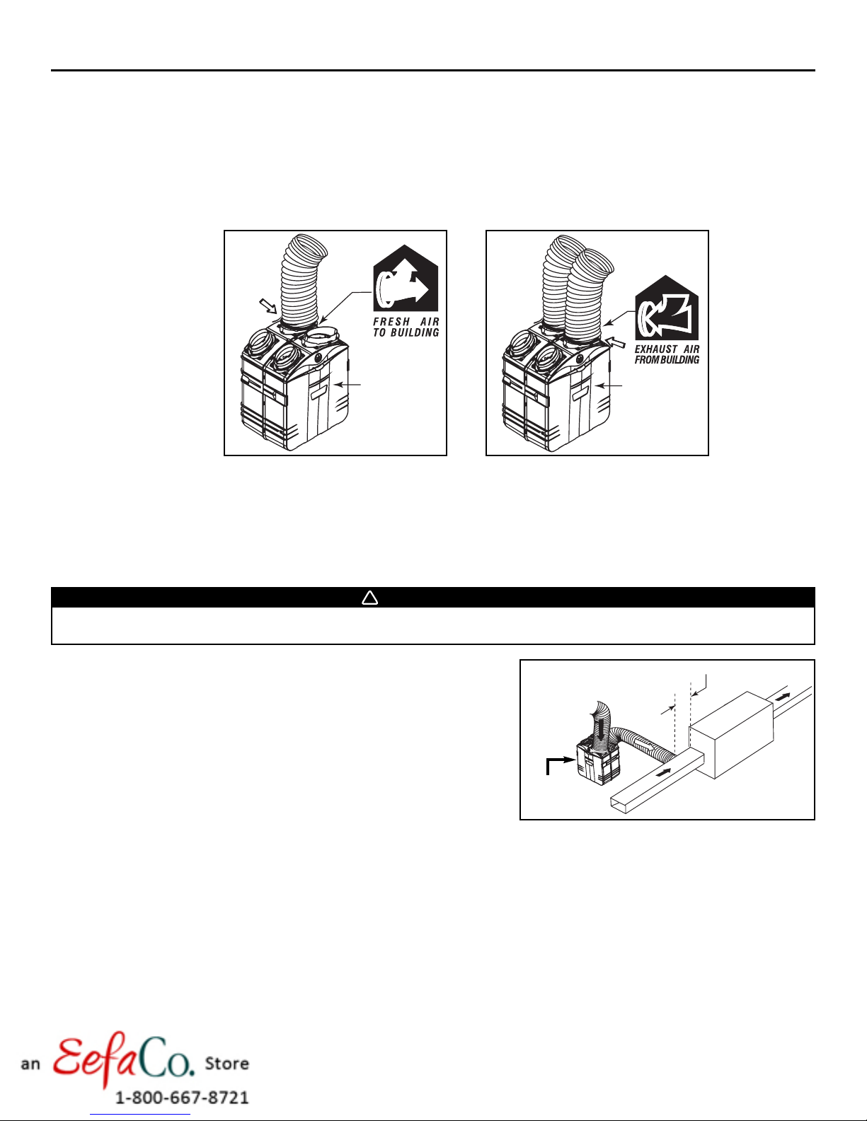
How to connect the 8’’ flexible duct to the unit duct connectors.
• Each port is identified on top of the unit (See illustrations below). Using the provided colored sticker dot, identify which duct it is
(red dot for stale airflow and blue dot for filtered airflow). Repeat the procedure for the other register.
• Attach the fresh air to building duct (the one with the blue dot) to its corresponding port, using tie wrap (1). Then, attach the exhaust
air from building duct (the one with the red dot) to the other 8’’ port (2).
12
Front door
of the unit
VJ0026A
VJ0027A
NOTE: Use 8’’ insulated duct only (not included) when ductwork may go where ambient temperature is over or below comfort zone.
6.5.2 CENTRAL DRAW POINT (AS ILLUSTRATED IN SECTION 5.4)
Stale air ductwork
Same as for Stand Alone System, described in point 6.5.1.
Filtered air ductwork (Return side connection)
Front door
of the unit
!
WARNING
When performing duct connections, always use approved tools and materials. Respect all corresponding laws and/or safety
regulations. Please refer to your local building code. Use only UL listed duct tape.
2 ft minimum
• Trace a 10 -1/4’’ long x 6 -7/8’’ high (260 mm x175mm) opening on the
furnace / air handler return duct at a minimum linear distance of 2 ft (0.61 m)
SUPPLY
upstream (return side) from furnace / air handler.
Front door
of the unit
VD0128A
RETURN
- 17 -
Page 18
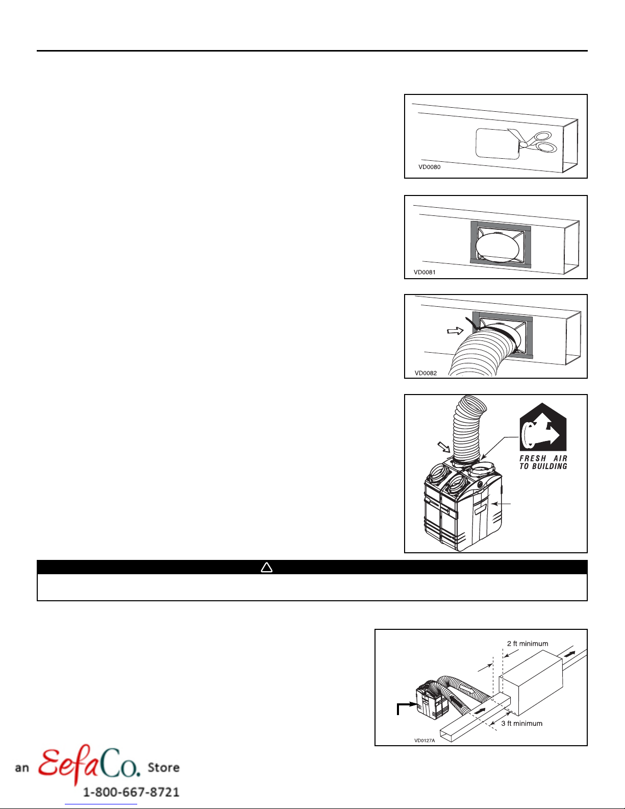
6. INSTALL THE UNIT (CONT’D)
6.5 INSTALLING 8’’ DUCTS AND REGISTERS (CONT’D)
6.5.2 C
ENTRAL DRAW POINT (AS ILLUSTRATED IN SECTION 5.4) (CONT’D)
• Using a metal shear or a hammer and a flat blade screwdriver, punch a hole into the
furnace / air handler return duct. Then, using metal shear, cut out the rectangular
hole.
• Fix the duct connector to the furnace / air handler duct using the provided four
retaining screws (#8 x 3/4”). Seal with UL approved duct tape.
• Take one end of the 8’’ flexible duct and slide it over the duct connector. Secure with
a tie wrap. Carefully seal the connection with UL approved duct tape. Identify the
duct using the blue sticker dot included.
• Attach this duct to the
FRESH AIR TO BUILDING
port (see icon on the top of the unit)
using tie wrap and duct tape.
Front door
of the unit
6.5.3 RETURN-TO-RETURN (AS ILLUSTRATED IN SECTION 5.5)
Filtered air ductwork (Return side connection)
!
WARNING
When performing duct connections, always use approved tools and materials. Respect all corresponding laws and/or safety
regulations. Please refer to your local building code. Use only UL listed duct tape.
Same as for Central draw Point, described in point 6.5.2.
VJ0026A
Stale air ductwork (Return side connection)
• Locate the return air inlet duct at least 2’ (0.61 m) upstream (return side) from
furnace / air handler. Locate the take-off duct opening at least 3’ (0.9m) from
the filtered air ductwork connection. Proceed as for the filtered air ductwork,
but instead of using the blue dot sticker to identify the duct, use the red dot.
Front door
of the unit
Minimum 3’
(0.9 m) from
filtered air
ductwork
connection
RETURN
SUPPLY
- 18 -
Page 19
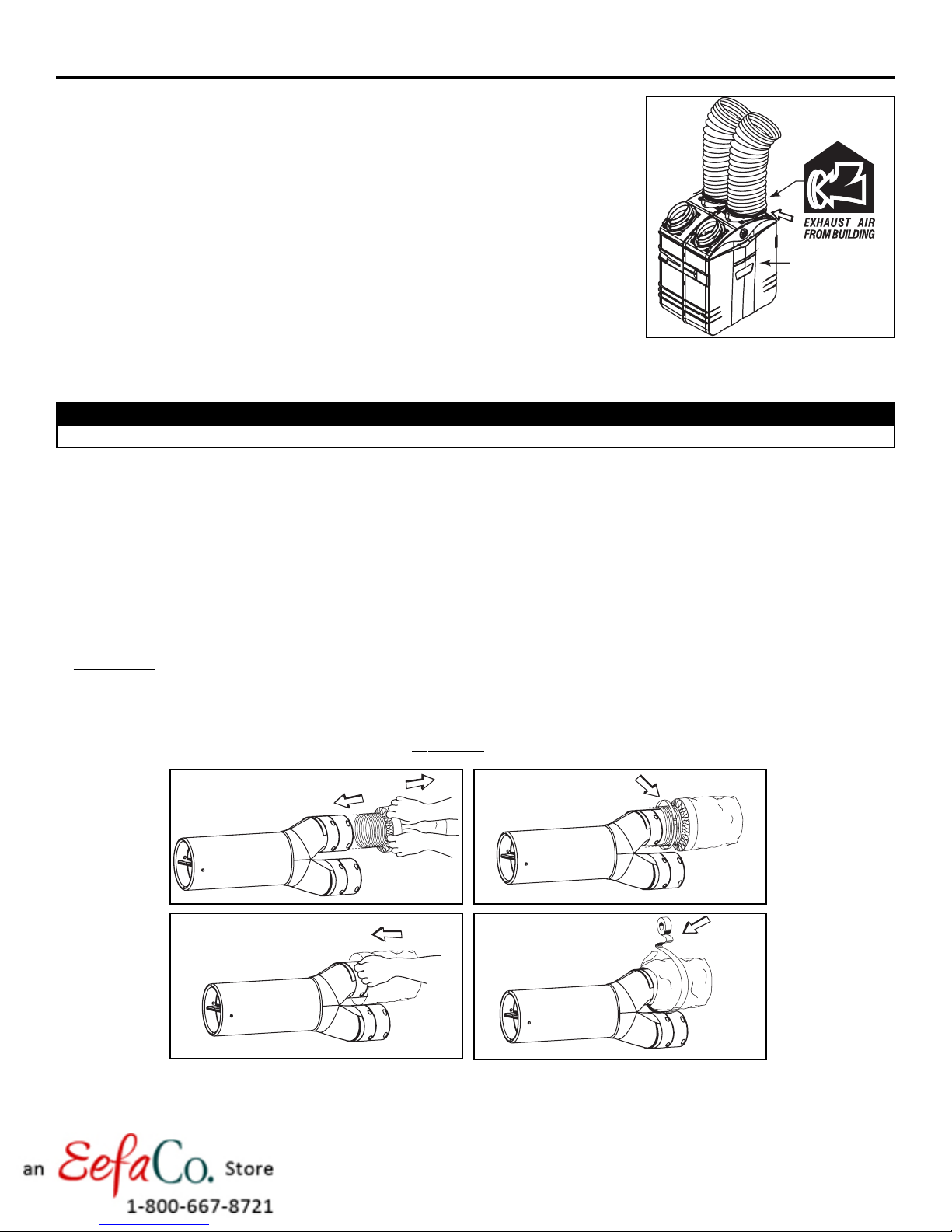
6. INSTALL THE UNIT (CONT’D)
6.5 INSTALLING 8’’ DUCTS AND REGISTERS (CONT’D)
6.5.3 R
• Attach this duct to the
ETURN-TO-RETURN (AS ILLUSTRATED IN SECTION 5.5) (CONT’D)
EXHAUST AIR FROM BUILDING
port (see icon on the top of the unit)
using tie wrap and duct tape.
Front door
of the unit
VJ0027A
®
6.6 INSTALLING INSULATED FLEXIBLE DUCTS TO TANDEM
T
RANSITION (GSVH1K, GSHH3K & GSEH3K MODELS ONLY)
CAUTION
Make sure the insulated ductwork vapor barrier does not tear during installation.
Use the following procedure for connecting the insulated flexible ducts to the Tandem®transition* (
FRESH AIR FROM OUTSIDE
).
*Patent pending.
NOTES: 1. If the joists are perpendicular to the ducts, or if the connection to the exterior hood is in a limited area, your installation will
need two exterior hoods instead of one AirDuo™ exterior hood. In this case, do not use the Tandem®transition.
2. If there is not sufficient space to install the Tandem®transition, both optional single exterior hood and AirDuo™ exterior hood
must be used. Identify each insulated duct. For fresh air from outside duct, use the blue sticker dots (one dot at each end).
For exhaust air to outside duct, use the red sticker dots (one dot at each end).
Then, go to Section 6.8 and then go to Section 6.10.
EXHAUST AIR TO OUTSIDE
and
6.6.1 CONNECTION TO TANDEM
®
TRANSITION
1. For each duct, pull back the insulation to expose the interior flexible duct.
2. Connect the interior flexible duct to the smaller part of the Tandem® transition (5’’ oval) using a 24’’ tie wrap.
NOTE: If you are using a 6’’ diameter insulated duct, use the bigger part of the Tandem® transition (6’’ oval).
3. Pull the insulation over the joint. Pull the vapor barrier over the insulation.
4. Apply duct tape gently to the joint in order to make an air
EXHAUST AIR TO OUTSIDE DUCT
1
VJ0025
ON TOP
3
VJ0023
tight seal. See figures below.
2
VJ0022
4
VJ0024
Identify each insulated duct. For fresh air from outside duct, use the blue sticker dots (one dot at each end). For exhaust air to outside
duct, use the red sticker dots (one dot at each end). Be careful to identify the exhaust air to outside duct (red dot) at the upper
section of the transition.
- 19 -
Page 20
6. INSTALL THE UNIT (CONT’D)
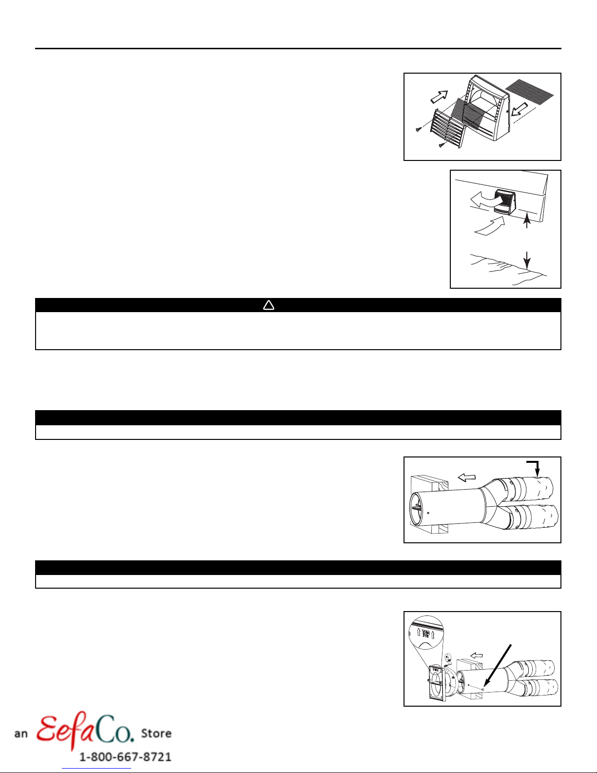
6.7 INSTALLING AIRDUO™EXTERIOR HOOD* (GSVH1K, GSHH3K AND GSEH3K MODELS ONLY)
6.7.1. ASSEMBLING AIRDUO™EXTERIOR HOOD
AirDuo™ exterior hood requires assembly. Assemble the top metal screen, the plastic grille
and the bottom metal screen to AirDuo™ exterior hood. Use provided screws. See illustration
beside.
*Patent pending
6.7.2 LOCATING THE AIRDUO™EXTERIOR HOOD
VO0024
The AirDuo™ exterior hood must be installed at a minimum distance of 18 inches (457 mm) above the
ground. See illustration beside.
VD0083
!
WARNING
Make sure this hood is at least 3 feet (0.9 m) away from any of the following:
• High efficiency furnace vent. • Any exhaust from a combustion source.
• Gas meter exhaust, gas barbecue-grill. • Garbage bin and any other source of contamination.
6.7.3 CONNECTING TANDEM® TRANSITION TO AIRDUO™ EXTERIOR HOOD
CAUTION
The Tandem® transition must be inserted in such a way that the
1. Using a jig saw, cut a 6’’ diameter hole in the exterior wall and insert the Tandem®
transition through this hole.
EXHAUST AIR TO OUTSIDE
duct will be located on the top.
EXHAUST AIR TO OUTSIDE duct
18''
(457 mm)
The exterior backplate must be installed with the word “TOP” pointing upward.
2. Joint the end of the Tandem® transition to the rear of the exterior backplate. Secure
with 2 Xmas tree pins and seal properly with duct tape.
VD0084
CAUTION
Xmas tree pin
VD0085
- 20 -
Page 21
6. INSTALL THE UNIT (CONT’D)
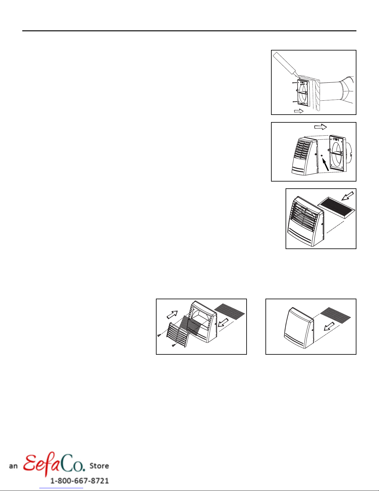
6.7 INSTALLING AIRDUO™EXTERIOR HOOD* (GSVH1K, GSHH3K AND GSEH3K MODELS ONLY) (CONT’D)
6.7.3 C
3. Attach the exterior backplate to the exterior wall. Using 4 #8 x 1 1/2” screws, fix it to the wall.
4. Snap the assembled AirDuo™ exterior hood on its backplate and secure with two
ONNECTING TANDEM® TRANSITION TO AIRDUO™ EXTERIOR HOOD (CONT’D)
Seal the outline with caulking, as shown.
VD0086
provided screws (#8 x 3/4” long). Go to Section 6.10.
6.7.4 OPTIONAL ALPINE/PINE FILTER
VD0087
screw
The special design of this filter makes it much more efficient to catch spores and their particles during
intensive pollen season. Using this optional fine mesh filter will extend the life expectancy of your prefilter.
To install it, remove the bottom metal screen of the AirDuo™ exterior hood and replace it by the optional
Alpine/pine filter. See illustration beside.
(Alpine/pine filter part number: ACCGSUP5)
VA0024
During pollen season, or as needed, remove the asembled hood from its backplate by removing its 2 retaining screws. Then, slide out
the Alpine/pine filter and clean it under water. Let dry before reinstalling it on the assembled hood. Reinstall the hood on its backplate.
6.8 INSTALLING TWO EXTERIOR HOODS* (GSVH1K, GSHH3K AND GSEH3K MODELS ONLY)
6.8.1 ASSEMBLING EXTERIOR HOODS
Both exterior AirDuo™ hood and optional exterior
single hood require assembly. Assemble the top
metal screen, the plastic grille and the bottom metal
screen to the AirDuo™ exterior hood*. Use provided
screws. Slide the bottom metal screen into the single
exterior hood base. See illustrations beside.
*Patent pending
VO0024
AirDuo™ EXTERIOR HOOD
VO0030
OPTIONAL SINGLE FRESH AIR INLET
EXTERIOR HOOD
- 21 -
Page 22
6. INSTALL THE UNIT (CONT’D)
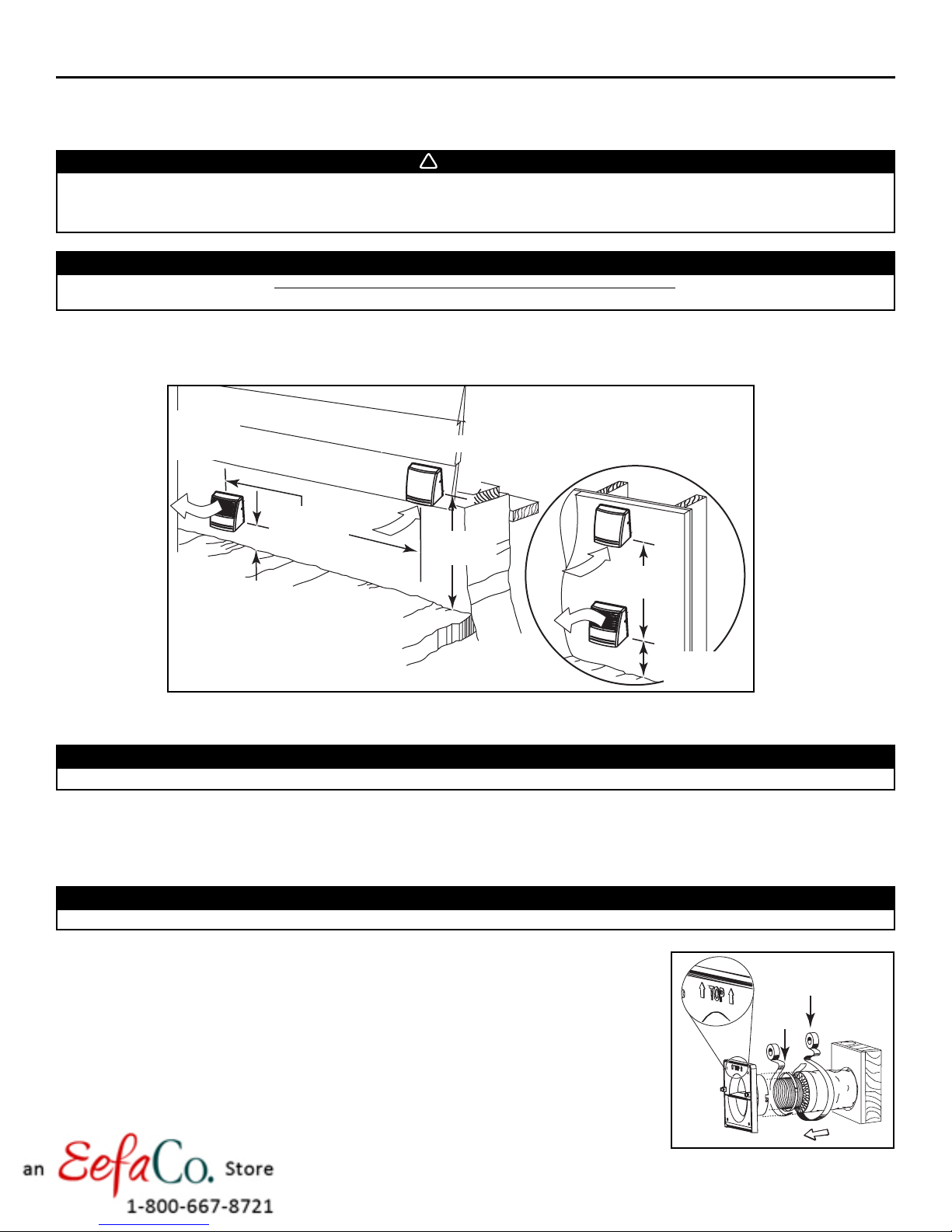
6.8 INSTALLING TWO EXTERIOR HOODS* (GSVH1K, GSHH3K AND GSEH3K MODELS ONLY) (CONT’D)
6.8.2 L
Make sure the AirDuo™ hood is at least 3 feet (0.9 m) away from any of the following:
• High efficiency furnace vent. • Any exhaust from a combustion source.
• Gas meter exhaust, gas barbecue-grill. • Garbage bin and any other source of contamination.
Due to its particular design, the AirDuo™ exterior hood must be used only for exhaust hood when performing an installation
using 2 exterior hoods. Use the optional single fresh air intake exterior hood for supply air.
The AirDuo™ exterior hood must be installed at a minimum distance of 4 inches (102 mm) from the ground, and the optional single fresh
air intake exterior hood must be installed at a minimum distance of 18 inches (457 mm) from the ground. Also, a minimum distance of
3 feet (0.9 m) is required between the hoods to avoid cross-contamination. See illustration below.
OCATING THE AIRDUO™ AND OPTIONAL EXTERIOR SINGLE HOOD
!
WARNING
CAUTION
AirDuo™
Exhaust
hood
3’
(914 mm)
4’’
(102 mm)
Intake hood
18’’
(457 mm)
3’
(914 mm)
4’’
(102 mm)
VD0094
Optional location
6.8.3 CONNECTING INSULATED DUCTS TO EXTERIOR HOODS
CAUTION
Make sure the insulated ductwork vapor barrier does not tear during installation.
1. For each exterior hood, using a jigsaw, cut a 6’’ diameter hole (if using 5’’ dia. insulated duct) or a 7’’ diameter hole (if using 6’’ dia.
insulated duct) in the exterior wall. Identify each insulated duct. For fresh air from outside duct, use the blue sticker dots (one at
each end). For exhaust to outside duct, use the red sticker dots (one dot at each end).Run each flexible duct through its respective hole
in the wall.
CAUTION
The exterior backplate must be installed with the word “TOP” pointing upward.
B
2. Pull back the insulation to expose the flexible duct and, using a tie wrap, attach it to the inner
ring of the exterior backplate (5’’ ring for the 5’’ insulated ducts or 6’’ ring for the 6’’ insulated
ducts). Carefully seal with duct tape (A). Pull the insulation over the joint. Pull the vapor barrier
over the insulation and over the outer ring of the exterior backplate. Apply gently duct tape to
the joint making an airtight seal (B).
A
VD0095
- 22 -
Page 23
6. INSTALL THE UNIT (CONT’D)
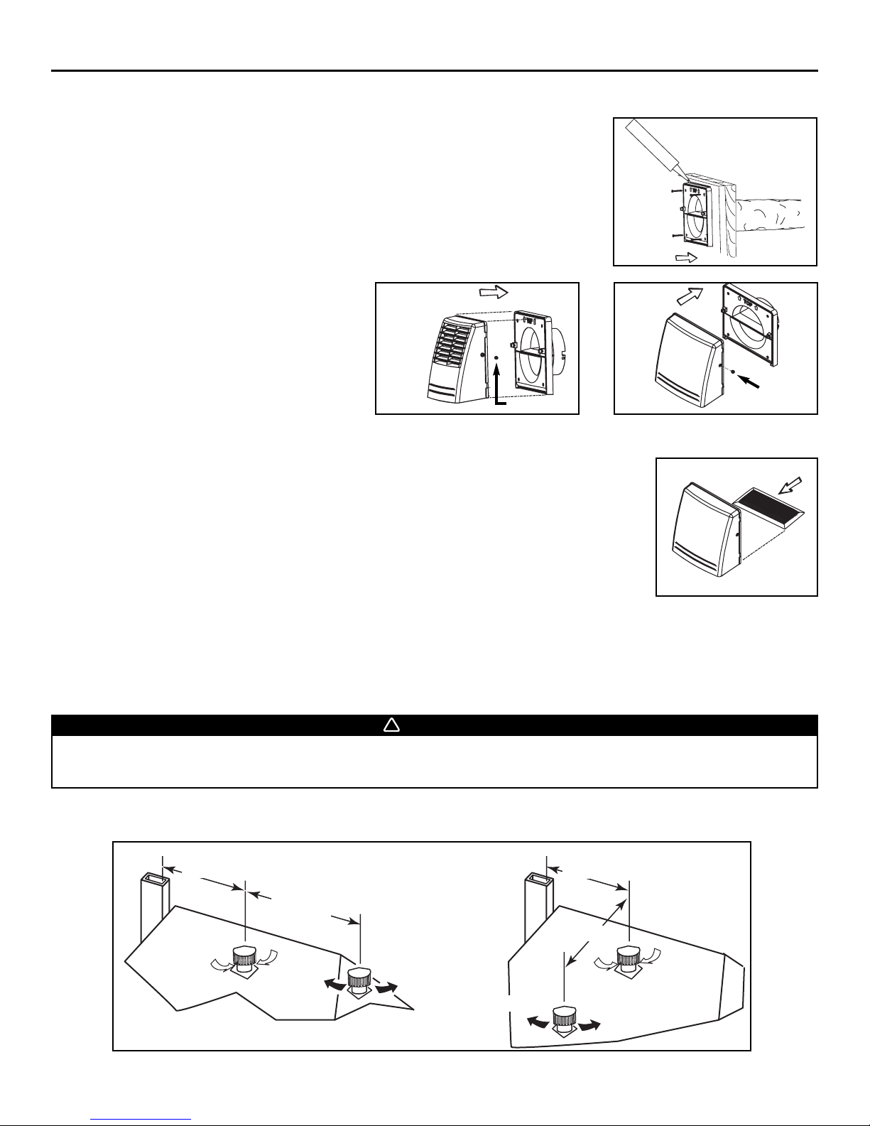
!
6.8 INSTALLING TWO EXTERIOR HOODS* (GSVH1K, GSHH3K AND GSEH3K MODELS ONLY) (CONT’D)
6.8.3 C
3. Attach the exterior backplate to the exterior wall. Using four provided screws, fix it to the wall.
Seal the backplate with caulking, as shown.
4. Snap each assembled exterior hood on its respective
backplate location and secure each of them with
their 2 provided screws.
ONNECTING INSULATED DUCTS TO EXTERIOR HOODS (CONT’D)
VD0096
VD0087
screw
VD0097
screw
AIRDUO™ EXTERIOR HOOD SINGLE EXTERIOR FRESH AIR INTAKE HOOD
6.8.4 OPTIONAL ALPINE/PINE FILTER
The special design of this filter makes it much more efficient to catch spores and their particles during
intensive pollen season. Using this optional fine mesh filter will extend the life expectancy of your prefilter.
To install it, remove the bottom metal screen of the optional exterior single hood and replace it by the
optional Alpine/pine filter. See illustration beside.
(Alpine/pine filter part number: ACCGSUP5)
VA0025
During pollen season, or as needed, remove the assembled hood from its backplate by removing its 2 retaining screws. Then, slide out
the Alpine/pine filter and clean it under water. Let dry before reinstalling it on the assembled hood. Reinstall the hood on its backplate.
6.9 INSTALLING TWO BREADERT CAPS (GSVH1K, GSHH3K AND GSEH3K MODELS ONLY)
6.9.1 LOCATING THE TWO BREADERT CAPS
WARNING
Make sure the Breadert Caps are at least 3 feet (0.9 m) away from any of the following:
• Chimney and any exhaust from a combustion source.
• Attic Ventilator
A minimum distance of 3 feet (0.9 m) is required between the Breadert caps (supplied by others) to avoid cross-contamination. Consider
the prevailing winds when locating these caps; the intake must be upstream the exhaust. See illustration below.
3’
(914 mm)
(914 mm)
Intake cap
VD0099
NOTE: Local requirements may vary.
3’
(914 mm)
3’
OR
Exhaust
cap
Exhaust cap
- 23 -
3’ (914 mm)
Intake cap
Page 24
6. INSTALL THE UNIT (CONT’D)
6.9 INSTALLING TWO BREADERT CAPS (GSVH1K, GSHH3K AND GSEH3K MODELS ONLY) (CONT’D)
6.9.2 C
Make sure the insulated ductwork vapor barrier does not tear during installation.
1. Install the Breadert caps as recommended by the manufacturer. Identify each insulated duct. For fresh air from outside duct, use
the blue sticker dots (one at each end). For exhaust to outside duct, use the red sticker dots (one dot at each end).
2. Connect the insulated ducts to their corresponding breidert caps.
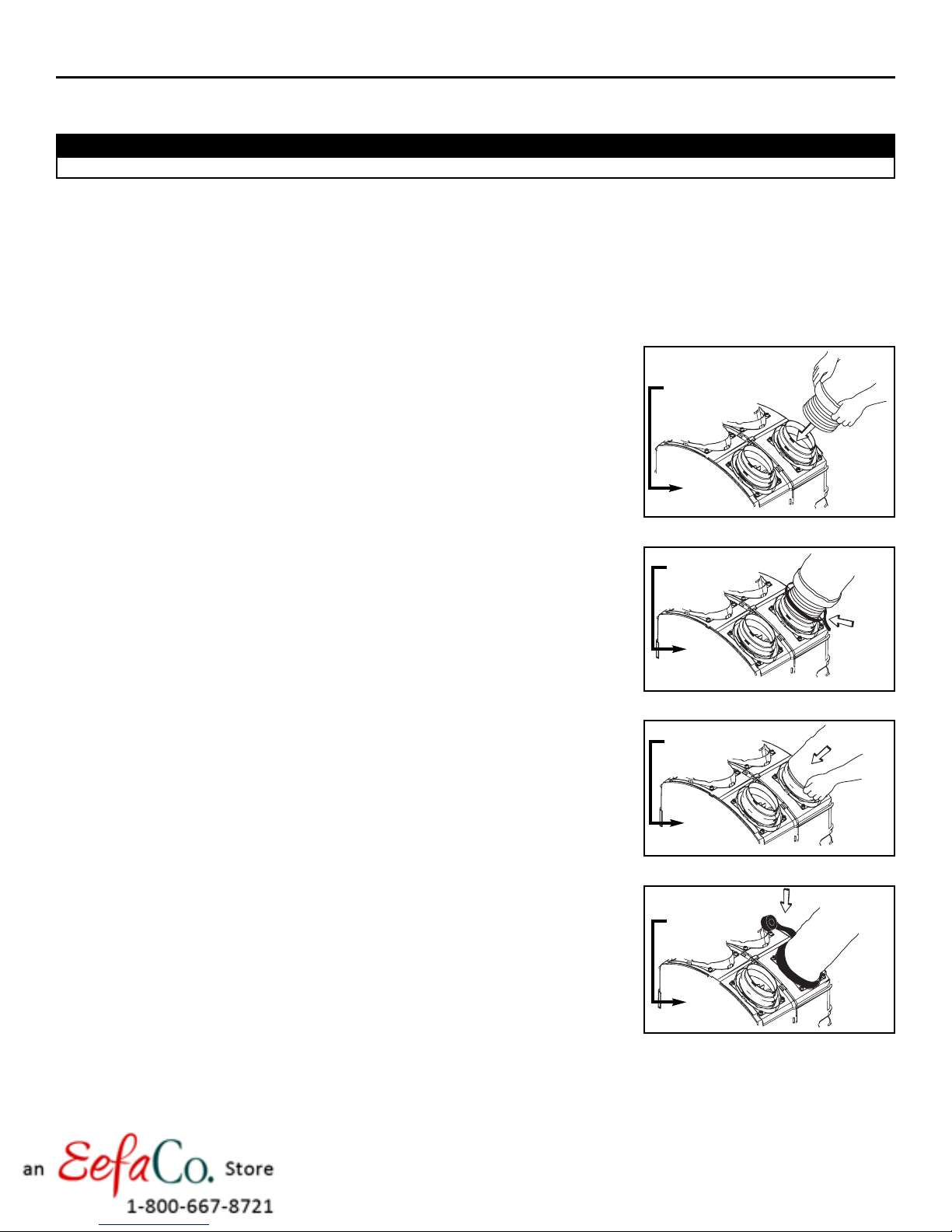
6.10 CONNECTION TO THE 5’’ TO 6’’ OVAL PORTS OF THE UNIT (GSVH1K, GSHH3K AND GSEH3K MODELS ONLY)
ONNECTING INSULATED DUCTS TO BREADERT CAPS
CAUTION
Use the following procedure for connecting the insulated flexible ducts to the 5’’ to 6’’ oval ports of the unit (
and
FRESH AIR FROM OUTSIDE
).
Rear side
of the unit
1. Pull back the insulation to expose the flexible duct.
VJ0016
Rear side
of the unit
2. Connect the interior flexible duct to the smaller part of the port (5’’ oval) using a
24’’ tie wrap.
NOTE: If you are using a 6’’ diameter insulated duct, use the bigger part of the
port (6’’ oval).
VJ0017
Rear side
of the unit
3. Pull the insulation over the joint and tuck it between the inner and outer rings of the port.
Pull the vapor barrier over the insulation and over the outer ring of the port.
EXHAUST AIR TO OUTSIDE
4. Apply duct tape gently to the joint in order to make an airtight seal.
VJ0018
Rear side
of the unit
VJ0019
- 24 -
Page 25
6. INSTALL THE UNIT (CONT’D)
6.10 CONNECTION TO THE 5’’ TO 6’’ OVAL PORTS OF THE UNIT
(GSVH1K, GSHH3K AND GSEH3K MODELS ONLY) (CONT’D)
5. Repeat steps 1 to 4 for all insulated ducts.
CAUTION
Avoid compressing the insulation when you pull the tape tightly around the joint. Compressed insulation loses its insulation
properties and causes water dripping due to condensation on the exterior surface of the duct.
1
2
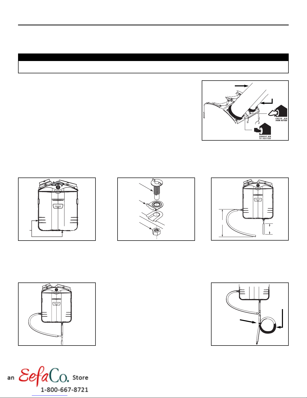
See figure beside to find the
and
FRESH AIR FROM OUTSIDE
EXHAUST AIR TO OUTSIDE
(2) oval ports on the top of the unit.
(1)
Be careful to connect the right insulated duct to its corresponding port.
6.11 CONNECTING THE DRAIN (GSHH3K MODEL ONLY)
1
2
3
1
VO0025
12
1. Open the door by turning the switch
knob to the OFF position (to unlock
the door). Then, unlatch the door
and open it. Slide out the core
assembly to access the 2 drain fitting
hole locations (1). Punch out the
holes.
VO0028
4
4. Join these 2 sections to the ‘’T’’
junction and main tube as shown.
2. Hand tighten the 2 plastic drain
5. Make a water trap loop in the tube to
VO0046
fittings (1) using the gaskets (2) and
nuts (3) as shown. Close the door.
prevent the unit from drawing
unpleasant odors from the drain
source. Make sure this loop is situated
BELOW the ‘’T’’ as shown. This will
prevent water from being drawn back
up into the unit in case of negative
pressure. Run the tube to the floor
drain or an alternative drain pipe or
pail. Be sure there is a slight slope
for the run-off.
Rear side
of the unit
VJ0028A
1) Red dot duct
2) Blue dot duct
27''
686 mm
VO0027
3. Cut 2 sections of plastic tubing; one
7’’(178 mm) long and one 27’’(686 mm)
long, and attach them to each drain
fitting as shown.
Tie-wrap
To drain
VO0029
'
(178 mm)
3
Water
5
- 25 -
Page 26
6. INSTALL THE UNIT (CONT’D)
6.12 LOW TEMPERATURE APPLICATIONS BELOW FREEZING (32°F OR 0°C)
ALL MODELS
CAUTION
When the ambient temperature surrounding the unit falls below freezing (32°F or 0°C), all units must run continuously to
prevent condensation.
FOR GSHH3K HEAT RECOVERY AND GSEH3K ENERGY RECOVERY MODELS ONLY
CAUTION
• When installing an GSHH3K HEPA Filtration, Fresh Air and Heat Recovery model, make sure the unit cabinet and its drain
line are protected from freezing.
• When installing an GSHH3K HEPA Filtration, Fresh Air and Heat Recovery model, install a drip pan if required by local code.
GENERAL:
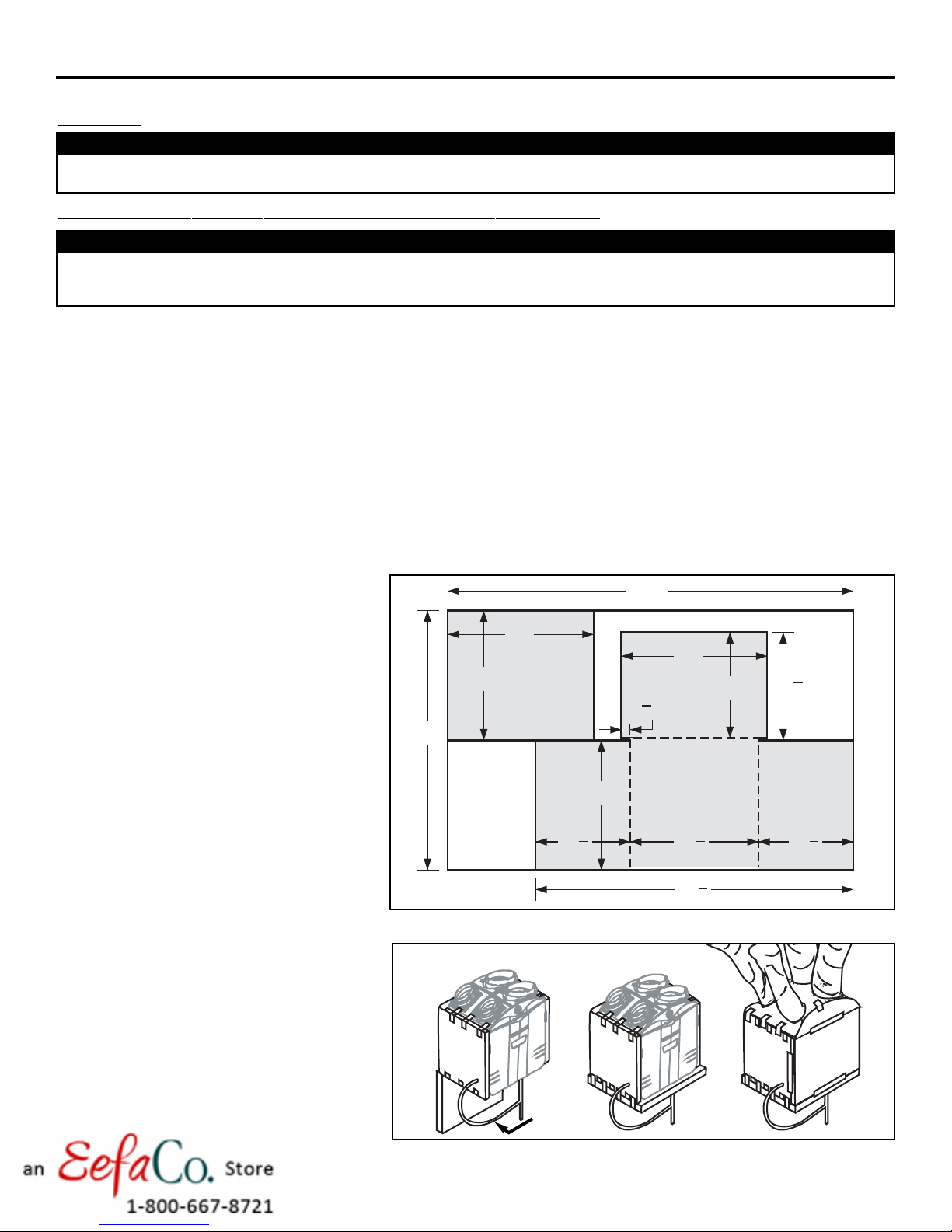
• Insulate the cabinet body using a 2” thick blanket insulation or by placing the unit in an insulated enclosure formed from 2” thick
fiberglass insulation board.
• Make sure that all ductwork is insulated.
• Carefully seal all of the unit ports with duct tape to prevent air leakage.
• Install a heating cable along the drain line for freeze protection.
- Use a UL listed heat tape in accordance to the manufacturer’s instruction.
- Because of the additional weight of the heating tape on drain line, secure the plastic tubing to each drain fitting using hose clamps
(not provided).
- Make sure the heat tape is rated between 3 to 6 watts per foot at 120 V.
- Protect the circuit the heat tape is connected to with a ground-fault circuit breaker.
- Cover the drain line and heating cable with 1/2 inch thick insulation.
- If you need to extend the drain line beyond the 9 foot length supplied with the unit, use copper pipe.
6.12.1 BLANKET INSULATION
75
27
27
Rectangular
If fabricating an insulation blanket, use a 2” thick hot
water heater blanket cut as shown.
48
VR0001A
24
Door
Insulation
17
Cut slots
1
2
inches
2
Bend UP 90
0
T-Shaped
24
1
2
Cabinet
Insulation
Wrap
Bend UP 90
23
58
5
19
8
0
Bend UP 90
3
4
3
4
Wrap the unit as shown. Make sure that all joints are fully sealed to prevent cold air penetration between the insulation and the unit.
NOTES: 1. Holes must be done in the insulation blanket
1 2
3
to allow drain line installation for model
GSHH3K only.
2. MAKE SURE to use excess insulation to
cover the top of unit and its ports.
1
20
8
0
1
17
2
VR0002
Heat
tape around
drain
- 26 -
Page 27
6. INSTALL THE UNIT (CONT’D)
6.12 LOW TEMPERATURE APPLICATIONS BELOW FREEZING (32°F OR 0°C) (CONT’D)
6.12.2 D
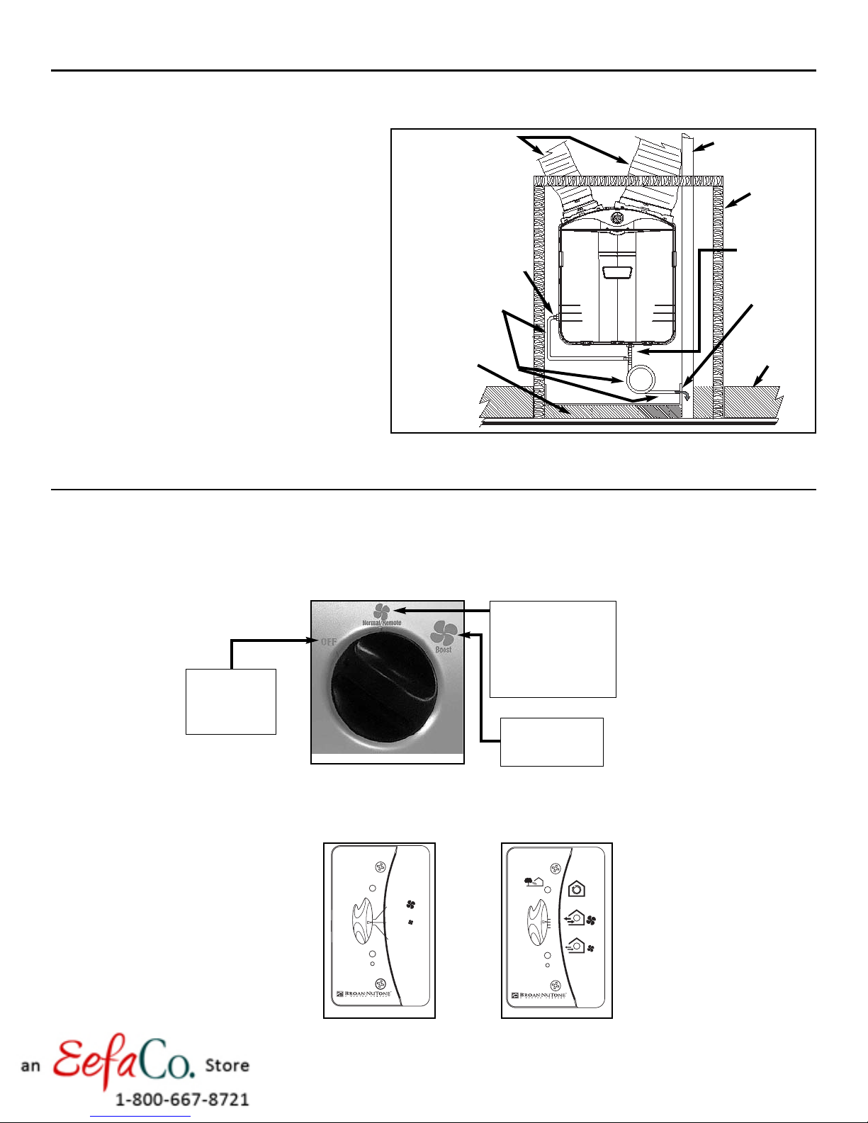
UCT BOARD INSULATED ENCLOSURE
Insulated
ducts
Waste
drain
2” Thick
ductboard
If fabricating an enclosure from 2” fiberglass duct board, make
sure that the enclosure is thightly sealed.
When possible have the waste disposal point within the
confines of the enclosure to expedite water removal (for
GSHH3K model only).
Remove
tape on
some attic
insulation to
allow heat into
Hose
clamp
Heat
drain
line
Hose
clamp
Optional
drain
pan
Attic
insulation
enclosure
from building
below
VH0044
CUT AWAY VIEW WITH THE DUCT BOARD ENCLOSURE DOOR REMOVED.
7. CONTROLS
7.1 MAIN SWITCH
All units are equipped with a 3-position main switch, located on the front panel. The unit is intented for use with a wall
controller (provided, see below).The main switch is to remain in either the “OFF” or “Normal/Remote” modes ONLY. The “Normal/Remote”
mode allows the homeowner to operate the product from the wall controller, typically mounted near a thermostat or other convenient
location.
NORMAL/REMOTE:
U
NIT IS OPERATING ON
LOW SPEED.THIS IS THE
RIGHT POSITION WHEN
OFF:
UNIT IS OFF AND
DOOR IS
UNLOCKED
.
VC0053
AN OPTIONAL WALL
CONTROL IS USED
BOOST:
U
NIT IS OPERATING
ON HIGH SPEED.
.
7.2 WALL CONTROLLERS (ONE PROVIDED WITH THE UNIT)
There are two wall controllers available: ACCGSC1 control (intended for GSFH1K and GSVH1K models only) and ACCGSC3 control
(intended for GSHH3K and GSEH3K models only).
VC0059
Power
Filter Maintenance
Reset Filter
High
Low
OFF
VC0060
Fresh air
Filter Maintenance
Reset Filter
Off
ACCGSC1 ACCGSC3
CONTROLLER CONTROLLER
- 27 -
Recirculation
High Ventilation
Low Ventilation
Page 28
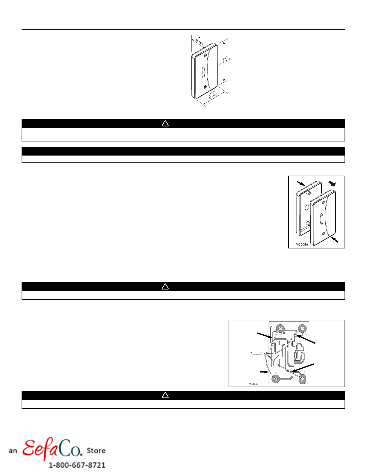
7. CONTROLS (CONT’D)
7.3 DIMENSIONS
Dimensions are the same for both models.
VC0049
7.4 INSTALLATION OF THE WALL CONTROLLERS (BOTH MODELS)
!
WARNING
Always disconnect the unit before making any connections. Failure in disconnecting power could result in electrical shock or
damage of the wall control or electronic module inside the unit.
CAUTION
Never install more than one optional wall control per unit.
1. Determine the more convenient location for the control.
2
2. Remove the controller cover plate (1). If you prefer to have your main control mounted on an
approved outlet box or an approved mounting bracket (not included), discard the backplate (2).
3. Route the control cable from the unit to the wall controller.
Use the provided cable (4-conductor, 24-gauge, Solid, UL Listed, CM type, 40’ long).
NOTE: For wall controller efficiency, the maximum wire length is 100’ (30.5 m). If needed, add another length of same wire type.
Use caution not to cross the wire colors or create any short.
!
WARNING
To avoid risk of electrical shocks, never install another wire in the same electrical box than the one for the wall controller.
4. Take one end of the provided cable and pass it through the wall control backplate (or outlet box or mounting bracket).
5. Splice back this end of the cable to access to the four wires. Remove the insulated
sleeve of each wire ends. Make a loop with each bare end wire to hook them to the
corresponding screw. Connect YELLOW wire to ‘’Y’’ screw, RED wire to “R’’ screw,
GREEN to “G’’ screw and BLACK to ‘’B’’ screw. See illustration beside.
BLACK
wire
GREEN
wire
YELLOW
wire
RED
wire
1
Make sure that the wires do not short circuit between themselves or by touching any other components on the wall controller.
!
WARNING
- 28 -
Page 29
7. CONTROLS (CONT’D)
7.4 INSTALLATION OF THE WALL CONTROLLERS (BOTH MODELS) (CONT’D)
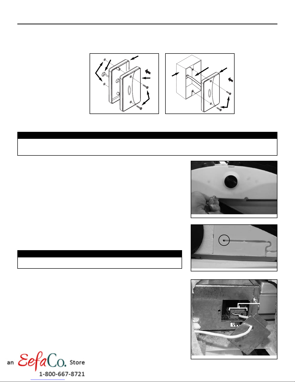
6. Reinstall the cover plate. Using provided wall anchors and provided screws, mount the wall controller on the wall. Use
only 2 screws to mount on outlet box. See illustrations below.
RECESS MOUNT
2
3
SURFACE MOUNT
2
3
1
4
1
5
VC0051
1) Wall anchors 4) Control 1) Outlet box 3) Control
2) Control cable 5) Screws 2) Control cable 4) Screws
3) Backplate
VC0052
4
CAUTION
Keep control low voltage wiring at least 1’ (305 mm) away from motors, lighting ballast, light dimming circuit and power
distribution panel. Do not route control wiring along house power wiring. Avoid poor wiring connections. Failure to follow
these practices can introduce electrical interference, which can cause erratic control operations.
7. Go to the unit. Remove the front panel by unscrewing its 2 retainig screws.
8. Using a small rod, pierce a hole through the unit at the end of the wire
channel. (See photo beside). Splice back the end of the cable to access the
four wires. Remove the insulated sleeve of each wire ends. Insert the end of
the cable through the unit, using the small hole previously done.
CAUTION
Never use a drill to pierce the hole through the unit, since electrical component
inside the unit may be damaged.
9. Looking inside the right side front port, you gain access the field wiring terminals for the
controller. Remove the side door located on the electrical box and punch out its knock
out. Run the cable through the knock-out hole and connect each wire to their
corresponding terminal (YELLOW in “Y’’, RED in “R’’, GREEN in “G’’ and BLACK in “B’’).
NOTE: Push forward slightly on the little tabs (1) to ease insertion of each wire.
See photo beside.
VO0019
VD0088
1
VE0049
- 29 -
Page 30
7. CONTROLS (CONT’D)
7.4 INSTALLATION OF THE WALL CONTROLLERS (BOTH MODELS) (CONT’D)
10. Reinstall the side door on the electrical box and install the 8’’ oval port on the unit.
11. Route the wire through its channel and reinstall the front panel on the unit.
See photo beside.
12. Plug the unit to the wall outlet.
NOTE: When using the wall controller, the main s
7.5 OPERATING ACCGSC1 CONTROLLER
witch on the unit must always be positioned to NORMAL/REMOTE.
VD0089
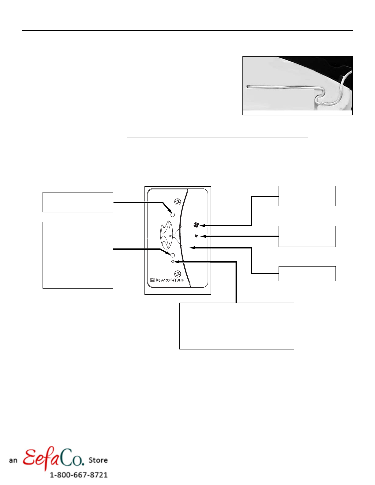
7.5.1 ACCGSC1 C
ONTROLLER DESCRIPTION
POWER INDICATOR:
LIGHTS UP WHEN SLIDE SWITCH
LOW OR HIGH POSITION.
IS ON
FILTER MAINTENANCE
INDICATOR
FLASHES EVERY MINUTE TO
INDICATE IT IS ON DUTY.
FLASHES EVERY SECOND WHEN
ITS TIME TO REPLACE
PREFILTER
.SEE SEMI-ANNUAL
:
MAINTENANCE IN SECTION 7.
LED STAYS LIT WHEN ITS TIME TO
REPLACE FILTER AND PREFILTER
HIGH:
NIT IS OPERATING ON
U
Power
Filter Maintenance
Reset Filter
High
Low
OFF
HIGH SPEED
NIT IS OPERATING ON
U
LOW SPEED
.
Low:
.
OFF:
NIT IS OFF.
U
.
VC0059
RESET FILTER HOLE:
O
NCE THE MAINTENANCE DONE, RESET THE FILTER
MAINTENANCE INDICATOR BY CAREFULLY INSERTING
A SMALL ROD (EG: PAPER CLIP) IN THE RESET FILTER
HOLE, FOR 1 SECOND.THE FILTER MAINTENANCE
INDICATOR WILL TURN OFF.REFER TO THE FILTER
MAINTENANCE RECOMMENDATIONS IN SECTION 8.
7.5.2 USING ACCGSC1 CONTROLLER
• OFF: To stop the unit, slide the button on this position.
• LOW: For a day-to-day usage, slide the button on this position.
The unit then will operate on low speed, providing 70 cfm.
• HIGH: For a high speed operation, slide the button on this position.
Generally used when more ventilation is required, such as parties, smokers, or for a 6-bedroom house.
This mode provides 105 cfm.
- 30 -
Page 31
7. CONTROLS (CONT’D)
7.6 OPERATING ACCGSC3 CONTROLLER
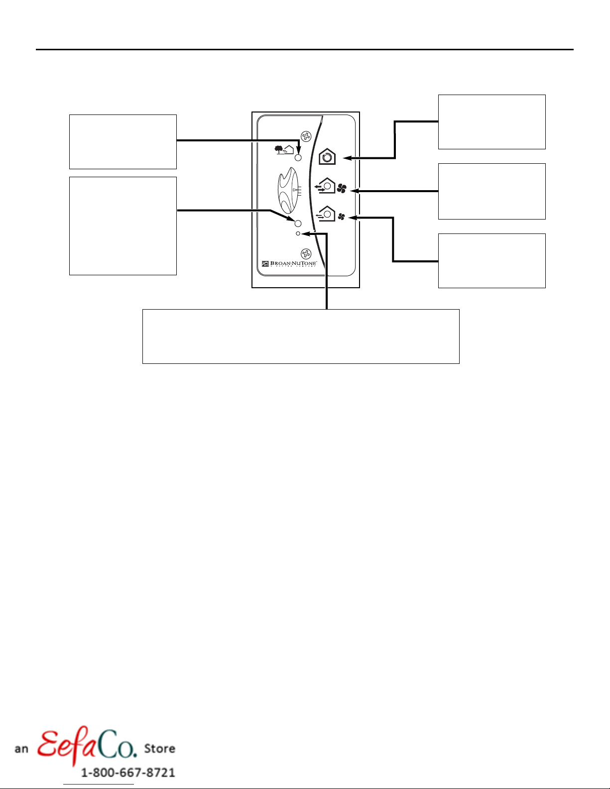
7.6.1 ACCGSC3 C
FRESH AIR INDICATOR:
LIGHTS UP WHEN SLIDE
SWITCH IS ON
ENTILATION OR BOOST
V
V
ENTILATION POSITION.
FILTER MAINTENANCE
INDICATOR
FLASHES WHEN IT IS TIME TO
REPLACE PREFILTER AND WASH
CORE AND CORE FILTERS
LED STAYS LIT WHEN IT IS
TIME TO REPLACE FILTER AND
PREFILTER AND CLEAN CORE
AND CORE FILTERS
ONTROLLER DESCRIPTION
NORMAL
:
.
.
NCE THE MAINTENANCE DONE, RESET THE FILTER MAINTENANCE INDICATOR BY CAREFULLY
O
INSERTING A SMALL ROD
HE FILTER MAINTENANCE INDICATOR WILL TURN OFF.REFER TO THE FILTER MAINTENANCE
T
RECOMMENDATIONS IN
(EG: PAPER CLIP) IN THE RESET FILTER HOLE, FOR 1 SECOND.
SECTION 8.
Fresh air
Off
Filter Maintenance
Reset Filter
VC0060
RESET FILTER HOLE:
Recirculation
High Ventilation
Low Ventilation
RECIRCULATION INDICATOR:
LIGHTS UP WHEN SLIDE
SWITCH IS ON
RECIRCULATION.UNIT IS
OPERATING ON LOW SPEED
.
HIGH VENTILATION INDICATOR:
LIGHTS UP WHEN SLIDE SWITCH
HIGH VENTILATION
IS ON
POSITION
.UNIT IS OPERATING
ON HIGH SPEED.
Low VENTILATION INDICATOR:
LIGHTS UP WHEN SLIDE SWITCH
IS ON
LOW VENTILATION
POSITION.UNIT IS OPERATING
ON NORMAL SPEED
.
7.6.2 USING ACCGSC3 CONTROLLER
• OFF: To stop the unit, slide the button on this position.
• LOW VENTILATION: For a day-to-day usage, slide the button on this position.
The unit then will operate on low speed, providing 70 cfm.
• HIGH VENTILATION: For a high speed operation, slide the button on this position.
Generally used when more ventilation is required, such as parties, smokers, or for a 6-bedroom house.
This mode provides 105 cfm.
• RECIRCULATION: For a low speed operation, without exchanging air with the outside, slide the button on this position.
This mode is recommended in high humidity days (rain, heat wave). Also, use it when the outside temperature is
extremely cold and/or the inside air is too dry. It can be used also to recirculate the heat coming from a wood
stove throughout the house, or the fresh air from a cooling system.
- 31 -
Page 32
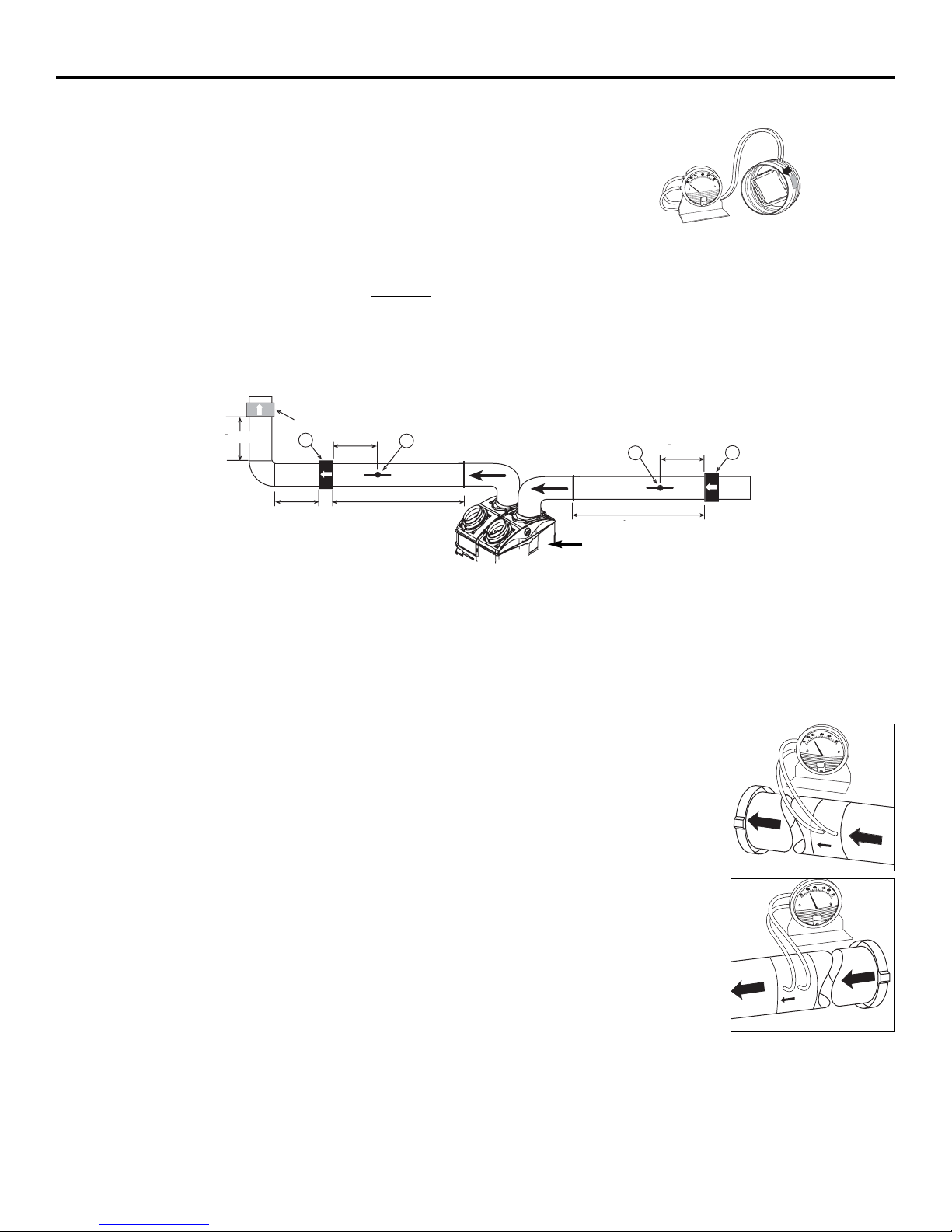
8. BALANCING PROCEDURE (GSVH1K, GSHH3K AND GSEH3K UNITS ONLY)
(
)
(30m)4m
36
(
)
36
(
)
O
B
G
)
2
(
)
L
OW
H
I
G
H
FL
OW
O
L
OW
H
I
G
H
F
L
OW
O
All units are prebalanced. However, if your construction code requires to balance the unit, follow this procedure.
8.1 WHAT YOU NEED TO BALANCE THE UNIT
• A magnehelic gauge capable of measuring 0 to 0.5 inches water gauge (0 to 125 Pa)
and 2 plastic tubes.
• Two flow collars (the size will vary depending of duct diameter).
VP0005
Flow collar
8.2 PRELIMINARY STAGES FOR BALANCING THE UNIT
Seal all the unit ductwork with tape. Close all windows and doors. Turn off all exhaust devices such as: range hoods, dryers and
bathroom fans. Make sure balancing dampers are fully open
(F and G in figure below).
Choose an appropriate location for the 2 flow collars according to figure below:
• On the exhaust air duct (first measuring location, A)
• On the fresh/filtered air distribution duct (second measuring location, B)
• At least 36” (914 mm) away from the unit; at least 12” (304 mm) before or after 90° elbow and at least 12” (304 mm) away from a register.
• At least 12” (304 mm) away a from a balancing damper (F and G in figure below).
R
VP0014A
304mm
12(304mm
914mm
FRONT DOOR
914mm
1
304mm
8.3 INSTALLATION OF FLOW COLLAR
Insert the flow collars in the ducts at each location (A et B on figure above). Make sure their arrows are pointing in the direction of the
airflow. Tape collars in place temporarily.
8.4 BALANCING PROCEDURE
1. Set the unit to high speed.
Make sure that the furnace blower is ON if the installation is in any way connected to the ductwork of the cold air return. If not leave
furnace blower OFF.
2. Place the magnehelic gauge on a level surface and adjust it to zero.
3. Connect tubing from gauge to flow collar in exhaust air stream (location A in illustration above). Be
sure to connect the tubes to their appropriate high / low fitting. If the gauge reading drops to below
zero, reverse the tubing connections.
NOTE: It is better to start with the exhaust air flow reading because the exhaust typically has more
restriction than the fresh air, especially in cases of stand alone and central draw point installations.
Hold or place the magnehelic gauge upright and level. Record the reading.
VP0003
4. Move tubing to the other side of the unit (location B in illustration above and note reading. Adjust the fresh
air balancing damper F until the reading at B is approximately the same as the reading at A. If the reading
at B is less than the reading at A then go back and adjust the exhaust balancing damper G to equal the
fresh air flow.
5. Remove flow collars and reconnect the duct, then, seal with duct tape. Write the required airflow information on a label and stick it
near the unit for future reference: (date, maximum speed airflows, your name and phone number and business address).
NOTES: 1. Most flow collar kits provide a conversion chart situated on the collar which enables you to convert magnehelic gauge readings
to equivalent cfm values.
2. A difference of ± 10 cfm ( ± 0.015 inches water gauge) between the 2 readings is considered balanced.
3. If you are using only one flow collar, then, after completing the first reading, transfer this measuring device to the other side
of the unit and take the second reading.
VP0004
- 32 -
Page 33
9. MAINTENANCE
!
WARNING
Risk of electrical shocks. Before performing any maintenance or servicing, always disconnect the unit from its power source.
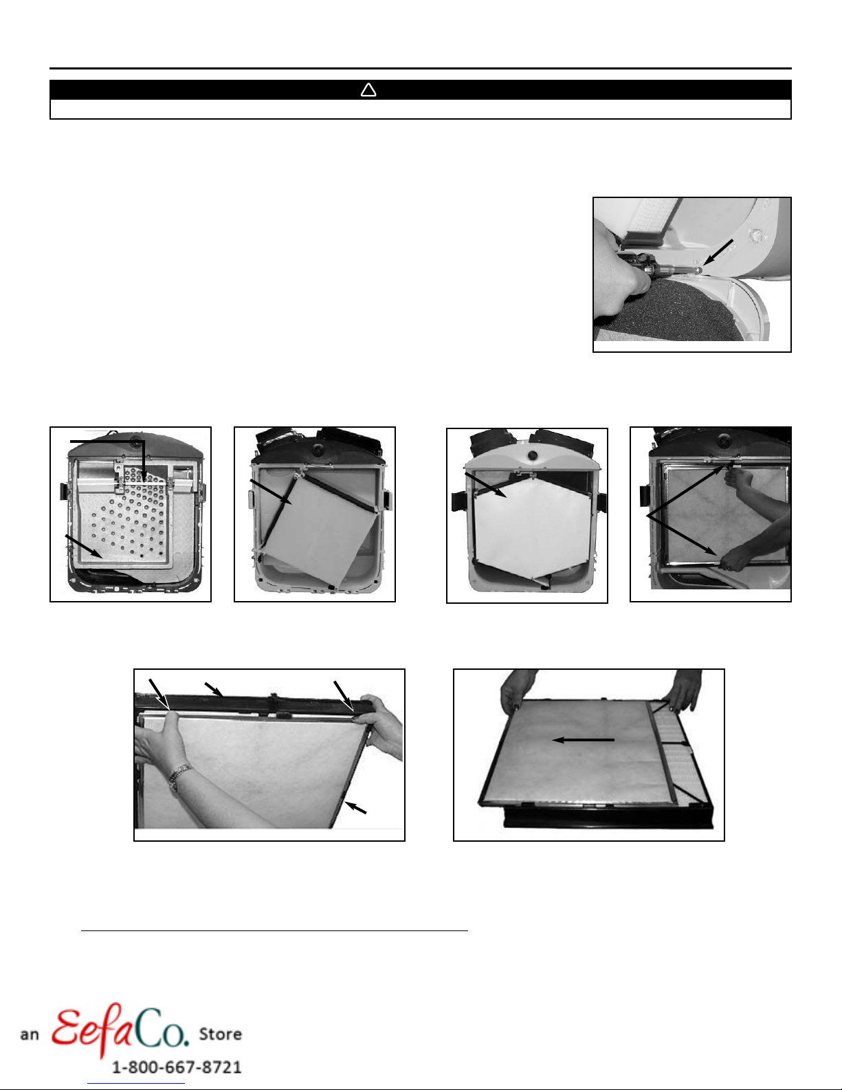
9.1 SEMI-ANNUAL MAINTENANCE (ESSENTIAL)
Your wall controller (ACCGSC1 or ACCGSC3) tells you when to perform this maintenance when the Filter Maintenance light is flashing.
Otherwise, maintenance should be performed every 6 months to ensure your unit proper operation for years to come. Follow these steps:
1. Turn switch knob to OFF to unlock the door.
2. Unlatch the door and open it. If required, the door can be removed.To do so, remove the stopper (A)
A
located on the right side of the door hinge. Then, hold the door and hit with your palm its left
side. Slide the door to the right to disengage it from the unit. Clean the inner side of the door
with a clean damp cloth, then wipe with a dry one.
VD0170
3. Slide out the air diffuser (model GSVH1K), the heat recovery module (model GSHH3K only), the energy recovery module (model
GSEH3K only) and the filter cartridge from the unit.
NOTES: 1. On model GSVH1K only, never grab the white shaft (item 2) to pull out the air diffuser.
2. To remove the filter cartridge, pull on its tabs.
2
3
4
5
1
VD0107
1) Air Diffuser 3) Heat recovery core 4) Energy recovery core 5) Filter cartridge tabs
2) White shaft
VD0091
4. Using your thumbs, push on the prefilter side to disengage it from the filter cartridge. Then, slide it out of the filter cartridge and discard
it. Install the new prefilter by reversing this operation.
VD0155
VD0112
1
VD0092
1) Filter cartridge
2) Prefilter
5. Clean the inside walls of the unit with a clean damp cloth, then wipe with a dry one. Reinstall the filter cartridge.
6.1 For HEP
Clean the air diffuser with a clean damp cloth, then wipe with a dry one. Once the air diffuser completely dry, slide it back into the unit.
A Filtration and Fresh Air Ventilation model GSVH1K only
2
VD0093
- 33 -
Page 34
9. MAINTENANCE (CONT’D)
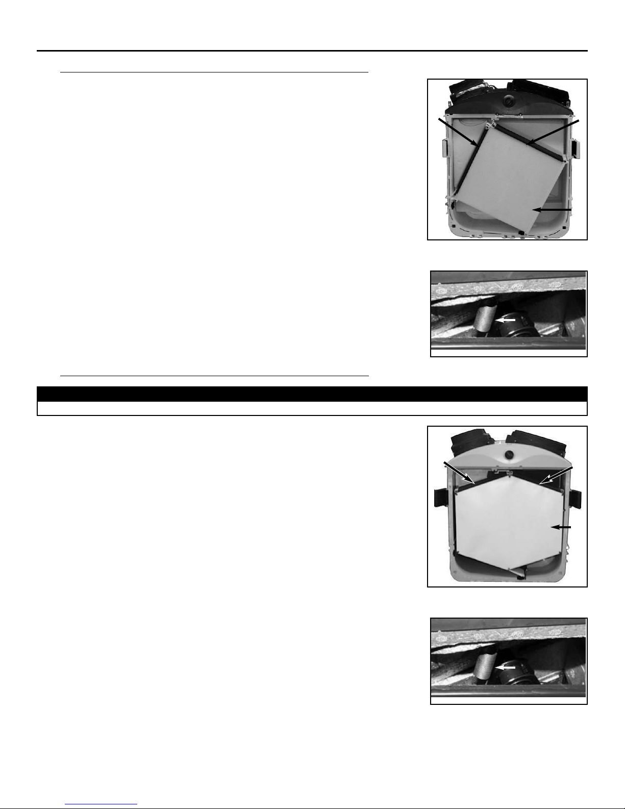
6.2 For HEPA Filtration, Fresh Air and Heat Recovery model GSHH3K only
Slide out the two core filters (item 1) from the heat recovery core and wash them under hot
water with mild soap.
Remove the dust on the heat recovery core (item 2) using a vacuum cleaner with a soft brush
attachment.
Rinse the core filters thoroughly and let dry before reinstalling them on the heat
recovery core.
Reinstall the heat recovery core in the unit.
NOTE: Make sure the damper spring (1) is still inside the left front port opening before
reinstalling the heat recovery module.
6.3 For HEPA Filtration, Fresh Air and Energy Recovery model GSEH3K only
CAUTION
The energy recovery core cannot be washed with water.
1
VD0091
1) Core filters
2) Heat Recovery Core
VD0120
1) Damper spring
1
2
1
1
Slide out the two core filters (item 1) from the energy recovery core and wash them under hot water
with mild soap.
Remove the dust on the energy recovery core (item 2) using a vacuum cleaner with a soft brush
attachment.
Rinse the core filters thoroughly and let dry before reinstalling them on the energy recovery
core.
Reinstall the energy recovery core in the unit.
VD0155
1) Core filters
2) Energy Recovery Core
NOTE: Make sure the damper spring (1) is still inside the left front port opening before
reinstalling the energy recovery module.
VD0120
1) Damper spring
7. If removed, reinstall the door and its stopper. Close the latches and turn ON the switch knob to its previous position.
8. Your unit is equipped with a wall controller (ACCGSC1 or ACCGSC3). Reset the filter maintenance indicator by inserting a small rod
(eg: paper clip end) into the reset filter hole of the wall control. Press lightly until the Filter Maintenance indicator light turns off.
- 34 -
1
1
2
Page 35

9. MAINTENANCE (CONT’D)
9.2 ANNUAL MAINTENANCE (ESSENTIAL)
Your unit is equipped with a wall controller (ACCGSC1 or ACCGSC3), which tells when to perform maintenance when the Filter
Maintenance light stays ON. Otherwise, this maintenance must be performed once a year to ensure your unit proper operation for years
to come. Proceed as the Semi-annual Maintenance (Section 9.1), but instead of replacing the prefilter (point 4), discard the complete
HEPA Filter cartridge (including prefilter). Install a new HEPA filter cartridge with a new prefilter on it.
9.3 MASTER RESET
Use the master reset only if you replace the filters before the annual maintenance indicator is on. By inserting a small rod (eg: paper clip
end) during 5 seconds and more into the reset filter hole of the wall controller, a master reset will be done and both semi-annual and
annual maintenance filter time clocks are reset.
A
CCGSC1 Control: The filter maintenance indicator will flash 1/4 second if the wall control is on Low or High position.
ACCGSC3 Control: If the wall control is in ”Off” position, “Fresh air” LED indicator will flash for 1 second.
If the wall control is in ”Lowl Ventilation” or “High Ventilation” position, the unit motor, the “Fresh air” light
indicator and fan speed LED indicator (“Low Ventilation” or “High Ventilation”) will turn off for 3 seconds.
If the wall control is in ”Recirculation” position, the “Recirculation” LED indicator and the unit motor will turn off for 3
seconds.
9.4 OPTIONAL ALPINE/PINE FILTER
During pollen season, or as needed, remove the assembled hood from its backplate by removing its 2 retaining screws. Then, slide out the
optional Alpine/pine filter and clean it under water. Let dry before reinstalling it on the assembled hood. Reinstall the hood on its backplate.
- 35 -
Page 36
10. TROUBLESHOOTING
PROBLEMS SOLUTIONS
• Check breaker or fuse in main distribution panel or GFI outlet.
1.Unit does not start at Low • Check there is 120V at the electrical outlet.
or High position. • Make sure the unit main switch is properly set in Normal or Boost position.
• If a wall control (ACCGSC1 or ACCGSC3) is connected, disconnect control wire from the
unit, then make sure the unit main switch is properly set in Normal/Remote or Boost
position.
• Check the fuse on electronic board. If blown, replace with the same type.
2. Unit does not run at Low • If a wall control (ACCGSC1 or ACCGSC3) is used, disconnect control wire from the unit.
speed, but runs at High. Then, if the unit runs at Normal speed, check control wiring and wall control connections.
3. Unit is not operating as per • Check if the unit main switch is in “Normal/Remote” position.
the selected mode. • Check wall control wiring.
4. Wall control indicators do not work
properly or not at all.
5. On ACCGSC3 wall control only,
1 or 2 light indicators are flashing
every second. • Check wall control wiring.
• Check wall control wiring.
• Check if the unit main switch is in “Normal/Remote” position.
11. WARRANTY
WHOLE-HOUSE AIR FILTRATION SYSTEM
WARRANTY
Broan-NuTone warrants to the original consumer purchaser of its products, that such products will be free from defects for a period of
two (2) years, from date of original purchase.
THERE ARE NO OTHER WARRANTIES, EXPRESS OR IMPLIED, INCLUDING, BUT NOT LIMITED TO, IMPLIED WARRANTIES OF
MERCHANTABILITY OR FITNESS FOR A PARTICULAR PURPOSE. BROAN-NUTONE WILL NOT BE HELD RESPONSIBLE FOR
ANY CLAIMS OVER THE ORIGINAL PURCHASE PRICE OF A BROAN-NUTONE WHOLE-HOUSE AIR FILTRATION SYSTEM,
NOR HELD RESPONSIBLE FOR SUBSEQUENT DAMAGE OR INCIDENT.
During the period stated above, Broan-NuTone will, at its opinion, repair or replace, without charge, any product or part which is found to
be defective under normal use and service. THIS WARRANTY DOES NOT EXTEND TO ANY FILTER, PREFILTER OR CORE FILTERS
(IF APPLICABLE). This warranty does not cover a) normal maintenance and service, b) any products or parts which have been subject to
misuse, negligence, accident, improper maintenance or repairs made by other than Broan-NuTone or c) a faulty installation or installation
contrary to recommended installation instructions.
The duration of any implied warranty is limited to the 2-year period as specified for the express warranty. Some states do not allow
limitation on how long an implied warranty lasts, so the above limitation may not apply to you.
BROAN-NUTONE’S OBLIGATION TO REPAIR OR REPLACE AT BROAN-NUTONE’S OPTION, SHALL BE THE PURCHASER'S
SOLE AND EXCLUSIVE REMEDY UNDER THIS WARRANTY. BROAN-NUTONE SHALL NOT BE LIABLE FOR INCIDENTAL,
CONSEQUENTIAL OR SPECIAL DAMAGES ARISING OUT OF OR IN CONNECTION WITH PRODUCT USE OR PERFORMANCE.
SOME STATES DO NOT ALLOW THE EXCLUSION OR LIMITATION OF INCIDENTAL OR CONSEQUENTIAL DAMAGES, SO THE
ABOVE LIMITATION OR EXCLUSION MAY NOT APPLY TO YOU.
This warranty gives you specific legal rights and you may also have other rights, which vary from state to state. This warranty supersedes
all prior warranties.
In order to qualify for a warranty claim, the owner of a Broan-NuTone WHOLE-HOUSE AIR FILTRATION SYSTEM must have the model and
serial number along with a proof of the original purchase date. In each case, costs for the removal of a defective part (and/or unit) and
installation of a new or repaired one and travel costs are not covered by this warranty.
BROAN-NUTONE LLC, 926 W. S STATE ST, HARTFORD WI 53027 1 800-637-1453
NUTONE INC., 4820 RED BANK ROAD, CINCINNATI, OH 45227 1 888-336-6151
99043105
 Loading...