

Page 1
Installation, Operation and Maintenance Guide
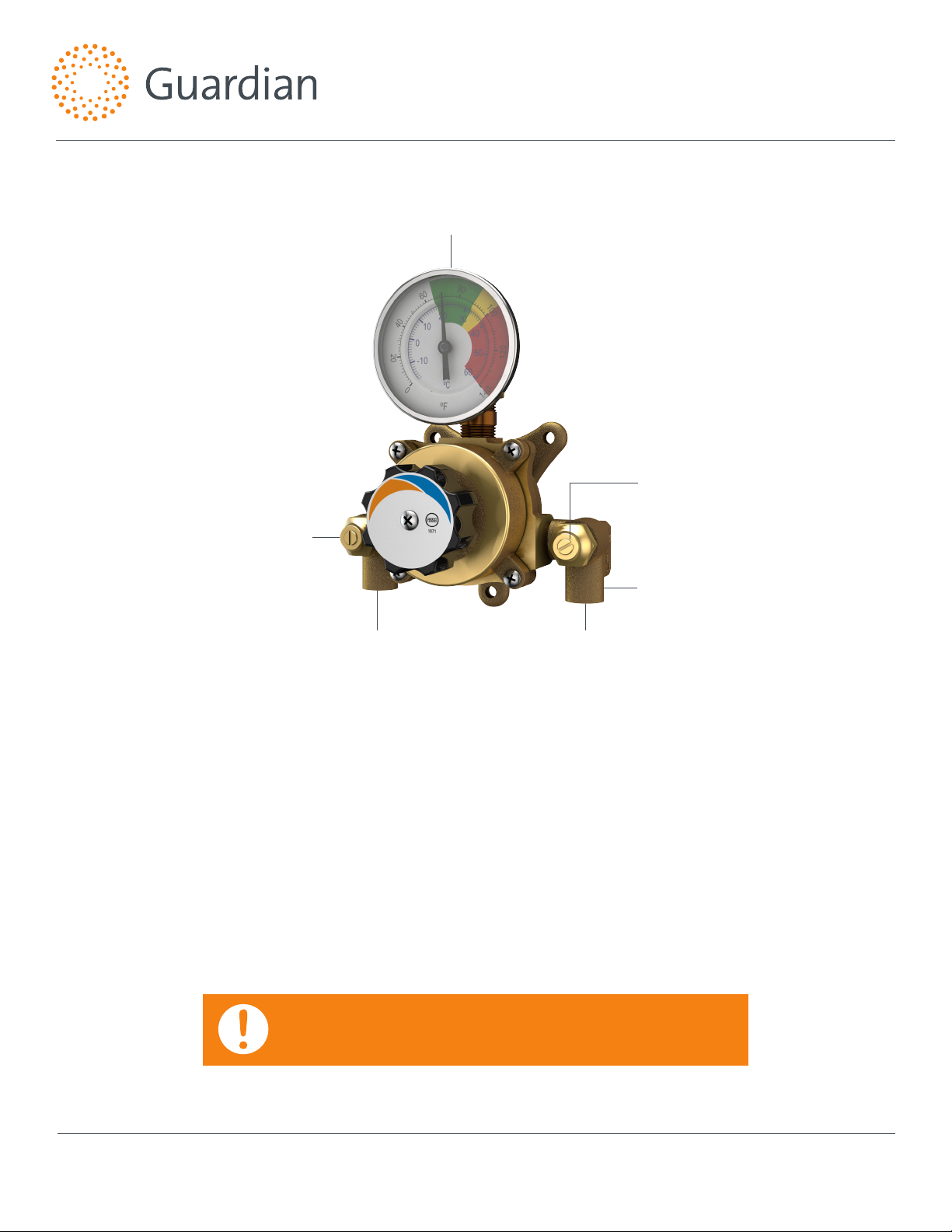
G3600LF Series Thermostatic Mixing Valves
Note: Please provide valve serial number (stamped on cover of valve) when ordering parts.
Thermometer
Angle Checkstop
Angle Checkstop
Hot Water
Inlet
G3600LF
Installation
1. Install valve in a location where it may be easily cleaned,
adjusted or repaired.
2. Inlets are clearly marked on valve body casting. Connect hot
water to inlet marked "HOT" and cold water to inlet marked
"COLD."
3. Included angle checkstops must be installed on both supply
lines (see above).
4. Use solder or pipe cement sparingly. Flush supply pipes
before connecting valve. Flush outlet pipe and valve once
valve is connected.
1/2" OD Copper
Tube Inlets
Cold Water
Inlet
Maximum operating pressure is 125 PSI (860 KPA) for hot and cold
water. Maximum hot to cold water pressure dierential is 5%.
Note: Should piping be exposed to excessive hot or cold conditions,
it may be necessary to insulate piping to prevent freezing or scalding
water.
IMPORTANT: THESE SYSTEMS ARE DESIGNED TO PROVIDE MIXED WATER
FROM 60 TO 90°F (15 TO 32°C) FOR EMERGENCY EYE OR EYE/FACE WASH
APPLICATIONS ONLY IN ACCORDANCE WITH ASSE 1071.
Note: This is a control system which must be cleaned and maintained regularly (see Maintenance Guide and Record card included with valve shipment).
Guardian Equipment
1140 N North Branch St
Chicago, IL 60642
312 447 8100 telephone
312 447 8101 facsimile
gesafety.com
rev. 1215 / © 2015 Guardian Equipment
1
Page 2
Adjustment and Service
Guardian Equipment thermostatic mixing valves may be easily
cleaned, adjusted and repaired. Servicing may be possible
without disconnecting valve.
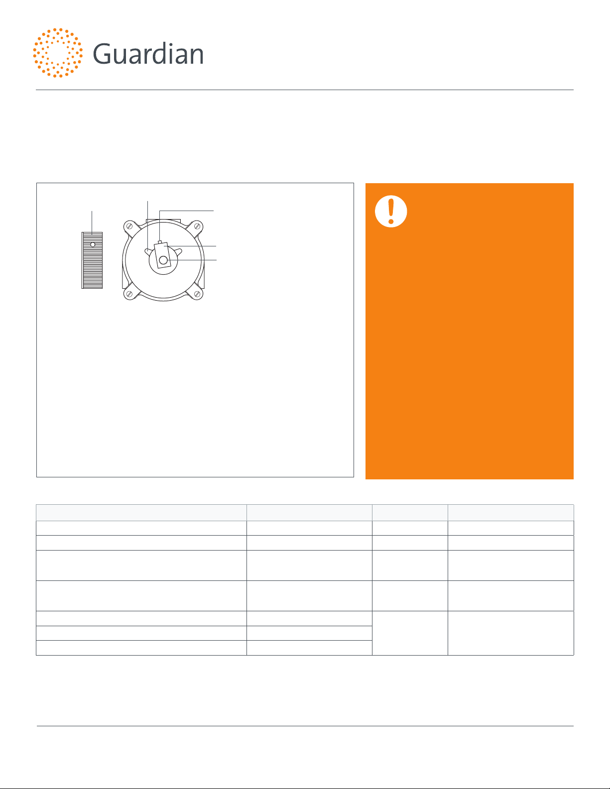
To Reset Adjustable High Temperature Limit Stop:
Installation, Operation and Maintenance Guide
G3600LF Series Thermostatic Mixing Valves
Note: Thermostatic water mixing valves are regulating mechanisms which
must be regularly maintained to provide best performance. Local water quality
and usage conditions dictate cleaning frequency. (See Maintenance Guide and
Record card included with valve shipment and reference ANSI Z358.1)
Handle
Set Screw
Stop
Retaining Ring
1. Remove handle, retaining ring, loosen set screw, and remove stop.
2. Activate emergency xture.
3. Replace handle and adjust to reach desired maximum temperature.
Note: Temperatures above 90°F are not recommended. Consult a
medical advisor for correct temperature settings.
4. Replace stop such that it rests against the web on the left side of the
cover.
5. Tighten set screw and reassemble. Hold a thermometer under water
ow to verify maximum temperature has been set appropriately.
Then set desired operating temperature.
Web
WARNING: THIS THERMOSTATIC
MIXING VALVE HAS AN ADJUSTABLE
HIGH TEMPERATURE LIMIT STOP
WHICH MUST BE CHECKED. IF
TEMPERATURE IS TOO HIGH, THE
INSTALLER MUST RESET THIS STOP
IMMEDIATELY. ALWAYS CHECK
THE TEMPERATURE OF THE MIXED
WATER WHEN THE LEVER HANDLE
IS TURNED TO FULL HOT. EXCESSIVE
HOT WATER TEMPERATURE IS
DANGEROUS AND MAY CAUSE
SCALDING.
THE HIGH TEMPERATURE LIMIT STOP
IS FACTORY SET AT APPROXIMATELY
90°F (32°C) WITH AN INCOMING HOT
WATER SUPPLY TEMPERATURE OF
135°F (57°C). IF THE INCOMING HOT
WATER TEMPERATURE IS HIGHER
THAN 135°F (57°C), THE VALVE
(WHEN TURNED TO FULL HOT) WILL
DELIVER WATER IN EXCESS OF 90°F
(32°C) AND THE HIGH TEMPERATURE
LIMIT STOP MUST BE RESET.
Troubleshooting
Symptom Component Type Part No. Description
Leak between valve cover and body. Packings and Gaskets 6806 Cover Gasket
Leak at lockable dial. Packings and Gaskets MU-5A O-Ring
Valve outlet temperature cannot be adjusted or will
not mix consistently.
After cleaning or replacing port sleeve assembly, valve
will not hold temperature.
Hot water bypass into cold line. Checkstops
Leak at checkstop bonnet. Checkstops
If installed on a circulated hot water system, verify the valve is piped according to Required Piping Method on page 3.
See page 5 for complete parts breakdown and parts kits.
Note: This is a control system which must be cleaned and maintained regularly (see Maintenance Guide and Record card included with valve shipment).
Guardian Equipment
1140 N North Branch St
Chicago, IL 60642
312 447 8100 telephone
312 447 8101 facsimile
gesafety.com
Port Sleeve Assembly TAG-1M or
RK3600A
Thermostat Group 6810 or
RK3600A
RK3600B Checkstop KitSupplies cannot be shut o completely. Checkstops
Port Sleeve Assembly or
Repair Kit
Thermostat Group or
Repair Kit
rev. 1215 / © 2015 Guardian Equipment
2
Page 3

Installation, Operation and Maintenance Guide
To Hot Water Source
Thermometer
Angle Checkstop
G3600LF Series Thermostatic Mixing Valves
Required Piping Method
Required when hot water must be circulated to a thermostatic mixing valve that is a substantial distance from the hot water
source. Recommended hot water inlet temperature is 135°F (57°C).
This unit must be cycled each time the emergency equipment is inspected (See ANSI Z358.1, Maintenance and Training section).
1. Set the thermostatic mixing valve to full hot.
2. Activate eye or eye/face wash and verify outlet temperature
does not exceed 90°F (32°C).
3. Turn thermostatic valve to full cold and wait ten seconds.
4. Turn thermostatic valve to full hot and wait ten seconds.
Angle Checkstop
1/2” OD Copper
Tube Inlets
Hot Inlet Cold Inlet
Hot Supply
Cold Supply
G3600LF
5. Verify outlet temperature does not exceed 90°F (32°C).
6. Turn thermostatic mixing valve to full cold and wait ten
seconds.
7. If necessary, adjust high temperature limit stop (see page 2).
Then set mixing valve to desired operating temperature and
deactivate emergency equipment.
Note: This is a control system which must be cleaned and maintained regularly (see Maintenance Guide and Record card included with valve shipment).
Guardian Equipment
1140 N North Branch St
Chicago, IL 60642
312 447 8100 telephone
312 447 8101 facsimile
gesafety.com
rev. 1215 / © 2015 Guardian Equipment
3
Page 4

Installation, Operation and Maintenance Guide
G3600LF Series Thermostatic Mixing Valves
To Dismantle Valve:
Turn o hot and cold water supplies to valve. Remove four
cover screws and remove cover and thermostat group. (Figure
1) After replacing parts, lockable dial must be reset to obtain
correct temperature range from Cold to Hot. (see "To Reset
Adjustable High Temperature Limit Stop" on page 2).
To Clean Port Sleeve Assembly:
Remove base stud (Figure 2). Twist port sleeve nut into valve
body, slide port sleeve assembly toward port sleeve nut, and
lift from valve body to clean. Clean with non-corrosive agent
and soft cloth. DO NOT USE ABRASIVES. Wash parts thoroughly
after cleaning and reassemble. Reinstall port sleeve assembly
with long slot end nearest port sleeve nut. Tighten port sleeve
nut to complete reassembly. DO NOT OVERTIGHTEN.
To Clean Thermostat Group:
Loosen set screw and remove handle (Figure 1). Remove
retaining ring and stop. Push rod through cover to remove
thermostat group. DO NOT PULL COILS OUT OF SHAPE. Use
brush and cleaning solution (non-corrosive and grit-free)
to remove any depost build-up from thermostat coil. Wash
thoroughly before reassembly.
Reassemble by reinstalling base stud, then place thermostat
group 6810 on base stud. PORT SLEEVE ASSEMBLY DRIVING
BALL MUST BE INSERTED INTO HOLE ON LOWER COIL
BRACKET(Figure 3). Verify thermostat moves back and forth.
Replace cover and screws and turn hot and cold water supplies
on. See page 2 "To Reset Adjustable High Temperature Limit
Sto p."
Figure 1
Figure 2
Long Slots
Figure 3
Base Stud
Port Sleeve Assembly
Cover
Screws
Base Stud
Port Sleeve Nut
Thermostat
Group
HandleStop
Port Sleeve Nut
Port Sleeve Assembly
Note: After installation, adjustment, and cleaning, always verify
valve temperature with thermometer when turned to full hot. If
necessary, adjust temperature of hot water source. EXCESSIVE
HOT WATER TEMPERATURE (OVER 90°F) IS DANGEROUS AND
MAY CAUSE SCALDING.
Driving Ball Coil Bracket
Note: This is a control system which must be cleaned and maintained regularly (see Maintenance Guide and Record card included with valve shipment).
Guardian Equipment
1140 N North Branch St
Chicago, IL 60642
312 447 8100 telephone
312 447 8101 facsimile
gesafety.com
rev. 1215 / © 2015 Guardian Equipment
4
Page 5

Thermostatic Mixing Valve Parts
8
Installation, Operation and Maintenance Guide
G3600LF Series Thermostatic Mixing Valves
10
1 9
7
Checkstop Parts Thermostat Group
RK3600B
Repair Kit*
11 12 13 1514 16
* Includes parts to repair both hot and cold checkstops
Lockable Dial
Set Screw
Notes:
1. After installing new parts, the adjustable high
temperature limit stop must be reset (see page 2).
2. G3600LF valves are furnished with lockable dials.
RK3600A
Repair Kit
108
2 4 53 6
7
6
9
Item Part Number Description
1
TA-5
2
MU-2C
3
6810
4
6820
5
68240
6
MU-5A
7
3009
8
TAG-1M
Note: This is a control system which must be cleaned and maintained regularly (see Maintenance Guide and Record card included with valve shipment).
Guardian Equipment
1140 N North Branch St
Chicago, IL 60642
Base Stud
Cover Screw
Thermostat Group
Stop
Handle
Stem O-Ring
Cover O-Ring
Port Sleeve Assembly
312 447 8100 telephone
312 447 8101 facsimile
gesafety.com
Item Part Number Description
9
10
11
12
13
14
15
16
6806
3402
LVC-8A
MU-6A
MU-9A
MU-5A
MU-4A
192700
Cover Gasket
Port Sleeve Nut
Check Bonnet Packing
Lower Stem with Packing
Check Spring
O-Ring
Upper Check Stem
Check Bonnet
rev. 1215 / © 2015 Guardian Equipment
5
Page 6

Flow Capacities
System Pressure Drop (PSI)
37.5
Flow Rate (GPM)
Installation, Operation and Maintenance Guide
G3600LF Series Thermostatic Mixing Valves
MODEL IN OUT
G3600LF 1/2" 1/2"
50
G3600LF
25
12.5
0
1 2 3 4 5 6 7 8 9 10
MINIMUM
FLOW
(GPM)
L/MIN 0.3 0.7 1.0 1.4 1.7 2.1 2.4 2.8 3.1 BAR
INTERNAL
COLD WATER
BYPASS
MINIMUM
5 10 15 20 25 30 35 40 45 PSI
SYSTEM PRESSURE DROP
2 4 2.0 2.7 3.5 4.5 5.5 6.5 7.5 8.5 9.0 GPM
7.6 15 7.6 10 13 17 21 25 28 32 34 L/MIN
MAXIMUM FLOW CAPACITY
G3600LF HAS 1/2" NOMINAL SWEAT CONNECTIONS.
CAUTION: ALL THERMOSTATIC MIXING VALVES HAVE
LIMITATIONS. THEY WILL NOT PROVIDE THE DESIRED
ACCURACY OUTSIDE OF THEIR FLOW CAPACITY
RANGE. CONSULT CAPACITY CHART AND DO NOT
OVERSIZE. MINIMUM FLOW MUST BE NO LESS THAN
SHOWN ABOVE.
Limited Warranty
Guardian Equipment warrants the original purchaser that its products will be free from defects in materials and workmanship under normal usage conditions,
and when properly installed and maintained according to manufacturer's instructions for a period of two years from date of shipment. During the warranty
period, Guardian Equipment will (at its discretion) repair or replace any product or part thereof, which shall be returned, freight prepaid to Guardian's factory
and determined by the manufacturer to be defective in materials or workmanship. There are no warranties, expressed or implied, which extend beyond verbiage
contained herein. There are no implied warranties of merchantability or tness for a particular purpose. Guardian Equipment will not be held liable for labor,
incidental or consequential damages. Any alteration or improper installation or improper use of the product will void this limited warranty.
Note: This is a control system which must be cleaned and maintained regularly (see Maintenance Guide and Record card included with valve shipment).
Guardian Equipment
1140 N North Branch St
Chicago, IL 60642
312 447 8100 telephone
312 447 8101 facsimile
gesafety.com
IMPORTANT: THESE SYSTEMS ARE DESIGNED TO
PROVIDE MIXED WATER FROM 60 TO 90°F (15 TO
32°C) FOR EYE OR EYE/FACE WASH APPLICATIONS
ONLY IN ACCORDANCE WITH ASSE 1071.
rev. 1215 / © 2015 Guardian Equipment
6
 Loading...