

Guardian Audio B6, B8 Owner's Manual
Maximum Power:
Send
Record
Input Impedance:
Channel EqualizaƟon:
High
Low
ProtecƟon Circuit:
180 was @ 4 ohms
120 was @ 8 ohms
‐10dBv 1k ohms
‐10dBv 1k ohms
Lo‐Z Mic 1k ohms
Hi‐Z Mic 10k ohms
Tape Playback 10k ohms
±15dB @ 5kHz
±15dB @ 60kHz
±15dB @ 60kHz
Power on mute 2 seconds
Guardian Audio is a registered trademark of MoAudio LLC.
Product and specificaons subject to change without noce.
B6 and B8
Owners Manual
Guardian Audio is a registered trademark of MoAudio LLC.
Product and specificaons subject to change without noce.
6 TCC Channel Powered Mixer
8 TCC Channel Powered Mixer
We use True Channel Count (TCC) on all Guardian Audio®
mixers. A mic channel consists of a minimum of an XLR input, EQ and level controls. A stereo channel consists of a
minimum of a pair of input jacks, EQ and level controls.
Page 2
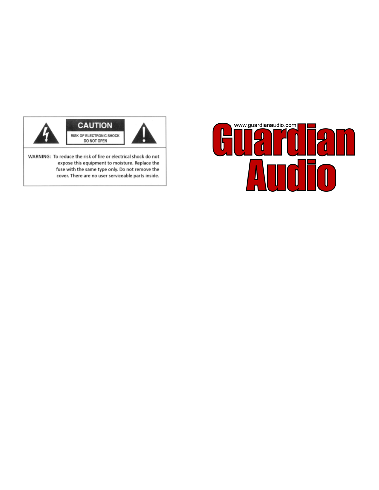
FRONT PANEL FEATURES
1) XLR low impedance balanced microphone input. Phan‐
tom power for condenser microphones. Input imped‐
ance is 10k ohms. The XLR connector is wired PIN 1 =
shield, PIN 2 = hot, PIN 3 = neutral.
2) 1/4” line high impedance input. This input can be used
for a high impedance microphone or line level device
such as keyboards, guitars and CD players. The input im‐
pedance is 10k ohms. Both high and low impedance
jacks can be used simultaneously.
3) Channel volume control. This control determines how
much signal is sent to the main bus.
4) EQ controls. These adjust the overall tone of the chan‐
nel. They cut or boost high and low frequencies ±15 dB.
5) Reverb control determines the amount of reverb effect
is sent to the main bus for each channel.
6) Master Volume controls the overall volume of the mixer
output.
7) Effects Controller adjusts the amount and delay me of
the reverb effects.
8) CD/Tape Volume controls the playback level of the RCA
inputs.
9) Tape Rec RCA jacks are for sending signal to a recorder.
These are pre‐master and do not have reverb or the
Tape Input signal.
Page 3
10) Tape Input RCA jacks are for tape/CD or other line level
signal. This is 10k ohm @ ‐10dBv.
11) Graphic Equalizer controls ±12dB of boost or cut at
60Hz, 250Hz, 800Hz, 2kHz and 8kHz.
12) Phantom Power turns the 15v phantom power on or off.
13) LED level display
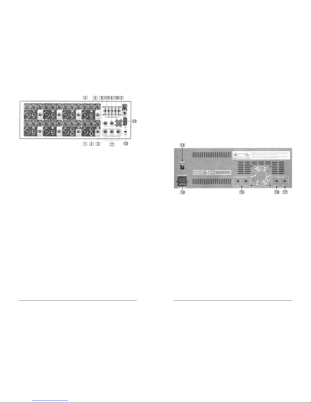
REAR PANEL FEATURES
14) Power Switch turns the mixer on and off. A front panel
LED lit indicates that the power is on.
15) Speaker output 1/4” jacks. The minimum impedance for
this amplifier is 4 ohms. A total of one 4 ohm or two 8 ohm
speakers may be connected. Do not operate below 4 ohms.
16) Effects Loop Send 1/4” jack for adding external effects,
recording out or adding an addional power amp. This line
level signal is a mirror of the main output.
17) Effects Loop Return 1/4” jack for adding external effects.
This is 10k ohm @ ‐10dBv.
18) 12) IEC connector for 115 volts 60 cycle grounded AC
current. Never operate without the ground pin.
 Loading...