

Guardian WRT-20, WRT-10, WRT-30, WRT-40 Installation & Operation Manual
Industrial Communications Worldwide
Weatherproof Industrial Telephones
WRT Series
Installation & Operation
WRT-10
WRT-20
P005418 Rev. E 090603 6/10/2009 3:31 PM
7552 - 10th Street N.E. Calgary, Alberta, Canada T2E 8W1
Ph: 403.258.3100 \ email:info@guardiantelecom.com \ www.guardiantelecom.com
WRT-30
WRT-40

Guardian Telecom Inc.
Installation and Operation
Model WRT
Table of Contents
Package Contents.................................................................................2
Overview...............................................................................................3
Standard Features On All Models.........................................................3
Features (Specific Models) ...................................................................4
Options Available..................................................................................4
Accessories...........................................................................................4
Installing the WRT.................................................................................7
Setting Dialing Mode.............................................................................8
Field Repairs & Adjustments.................................................................9
Programming The WRT-20 With Membrane Keypad .........................10
Operating the WRT.............................................................................10
Engineering Specifications..................................................................11
Replacement Parts..............................................................................12
Government Certification ....................................................................13
Warranty..............................................................................................14
Disclaimer ...........................................................................................14
Warning...............................................................................................14
Service Telephone Number ................................................................14
Feedback ............................................................................................14
Guardian Product Return....................................................................15
Table of Figures
Figure 1 - Features - Typical - Standard Models...................................5
Figure 2 - Overall Dimensions - Standard Models................................5
Figure 3 - Features WRT-20 with Optional Mounting Plate .................6
Figure 4 - Overall Dimensions WRT-20 with Optional Mounting Plate 6
Figure 5 - Setting Dialing Mode & Installation.......................................8
Figure 6 - Fuse Replacement................................................................9
Package Contents
(1) WRT Telephone
(1) Installation & Operation Manual
Page 2

Guardian Telecom Inc.
Installation and Operation
Model WRT
Overview
WRT Series Weather Resistant Telephones
WRT telephones are designed to provide safe, reliable communication in areas prone to high
humidity, chemical vapors, dust and physical abuse. Several variations and options are available to
suit the end user’s requirements.
Standard Features On All Models
Enclosure
• weather tight, rugged Valox
• spring loaded hinged door
Faceplate
• 16 Gauge steel with wiring access to surge arrestor
Encapsulated Circuitry
• circuit boards are resistant to corrosive agents (e.g. H
NH
), and environments with high humidity
3
Surge Arrestor
• protects the user in the event of a high voltage spike on the telephone
line
Fuse
• prevents damage to the electronic circuits in the event of a high
voltage spike on the telephone line
Magnetic Reed Hook Switch
• no moving parts
Tone (DTMF) Operation
• factory set to tone (DTMF) dialing
• pulse dialing can be ordered or configured in the field
6’ Heavy Duty Handset Cord (Not Available With WRT-40)
• withstands severe use
Hearing-Aid Compatible (HAC) Receiver
• compatible with inductively coupled hearing-aid devices
Receiver Volume Control
• Switch in handset (on keypad of WRT-20), provides 13.5dB of range
®
& steel
S, SO2, and
2
Page 3

Guardian Telecom Inc.
Installation and Operation
Model WRT
Features (Specific Models)
P6072 WRT-10
• Waterproof 3 x 4 Keypad
• 6’ Heavy duty handset cord
P6073 WRT-20
• Membrane Keypad With Features
weather tight
10 number memory
Redial - last number (31 digits)
Recall - obtains dial tone without hanging up handset
Flash - 600ms timed loop break
Pause - 3 second pause in programming
Mute - disables handset microphone
Softer/Louder – 2.7dB steps (+8.1dB/-5.4dB 3 steps up, 2
steps down)
• 6’ Heavy duty handset cord
P6074 WRT-30
• Metal 3 x 4 Keypad
• 6’ Heavy duty handset cord
P6075 WRT-40
• Metal 3 x 4 Keypad
• 22” Armored Handset Cord
• Handset Retainer Clips
• Stainless Steel Mounting Plate
Options Available
Stainless Steel Mounting Plate (MP) (Standard on WRT-40)
20’ Heavy Duty Curly Cord (20C) (Only on WRT-20)
20’ Heavy Duty Curly Cord (20VC) (Only on WRT-10/30)
Noise Canceling Microphone (NC)
Grey Enclosure (GR)
Accessories
• P7224 Potted ring detect relay
• P7225 Weather Proof ring detect relay
• P7227 Potted off-hook detect relay
• P7232 Weather Proof off-hook detect relay
• PXXXX External Loud Ringer
Page 4
Guardian Telecom Inc.
Installation and Operation
Model WRT
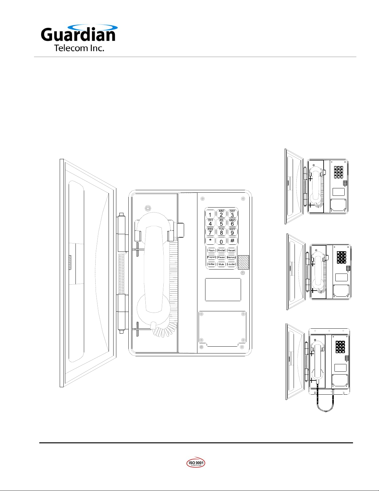
MAGNETIC REED HOOK SWITCH
3X4 KEYPAD
(WRT-10 WATERPROOF,WRT-30
& WRT-40 METAL)
FACEPLATE - 16 GA STEEL, SATIN
COAT PRIMED AND POWDER COATED
VELCRO DOOR LATCH
ID & APPROVALS
HEAVY DUTY HANDSET CORD
WIRING ACCESS PLATE
Figure 1 - Features - Typical - Standard Models
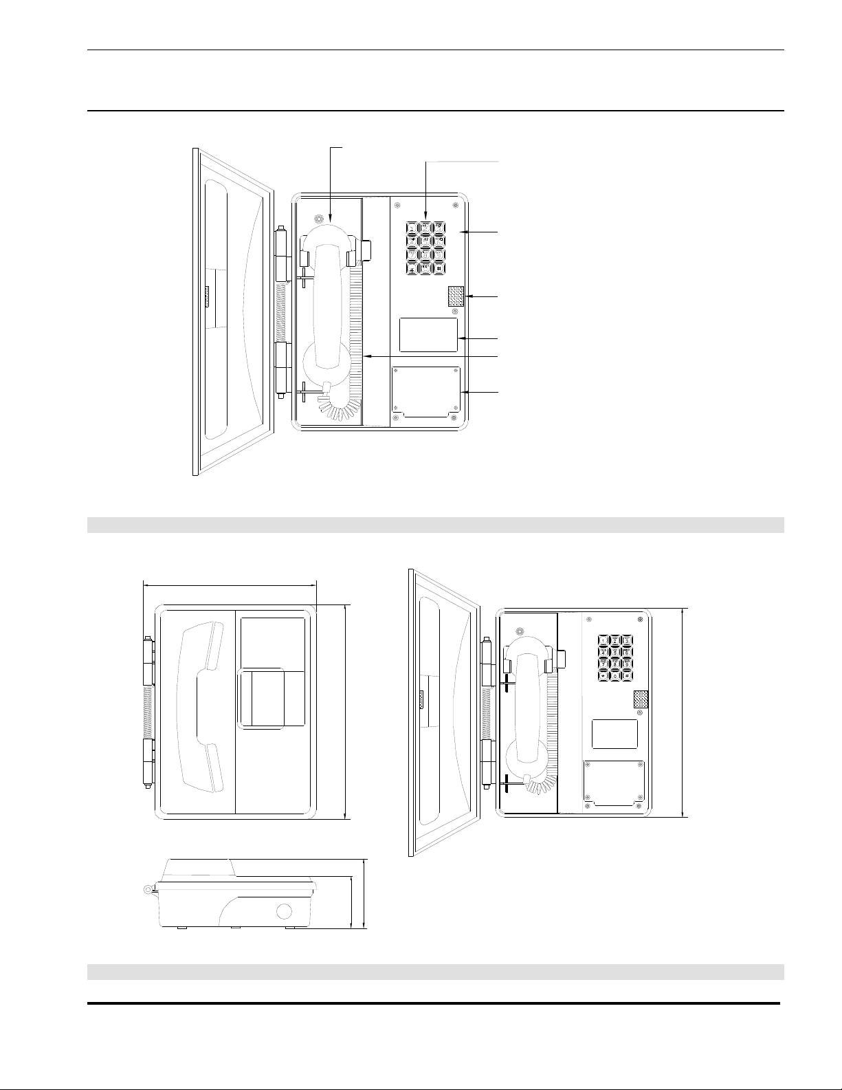
9.7" [246mm]
12.0" [305mm]
11.8" [300mm]
3.8" [97mm]
2.9" [74mm]
Figure 2 - Overall Dimensions - Standard Models
Page 5
 Loading...