

Page 1
Industrial Communications Worldwide
Waterproof 4X Telephone
Model WP80
Installation and Operation
1
2 3
4
7
0
*
P004963 Rev. D 11/23/2004 11:43
Ph: 403.258.3100 \ email:info@guardiantelecom.com \ www.guardiantelecom.com
7552 - 10th Street N.E. Calgary, Alberta, Canada T2E 8W1
65
98
#
Page 2

Guardian Telecom Inc.
Installation and Operation
Table of Contents
Overview ....................................................................................................................3
Features.....................................................................................................................3
Installing the WP80 ....................................................................................................5
Maintenance...............................................................................................................6
Operation ...................................................................................................................6
Fuse Replacement.....................................................................................................6
Engineering Specifications.........................................................................................7
Models and Options ...................................................................................................8
Accessories................................................................................................................8
Warranty.....................................................................................................................9
Disclaimer ..................................................................................................................9
Warning......................................................................................................................9
Service Telephone Number........................................................................................9
Feedback ...................................................................................................................9
Guardian Product Return .........................................................................................10
Model WP80
Table of Figures
Figure 1 - Overall Dimensions....................................................................................4
Figure 2 - Installation..................................................................................................4
Figure 3 - Setting Dialing Mode..................................................................................5
Package Contents
(1) WP80 Telephone with mounting plate
(2) Door Latch Keys
(1) Driver Bit
(14) Faceplate Screws
(1) Installation and Operation Manual
Page 2
Page 3

Guardian Telecom Inc.
Installation and Operation
Model WP80
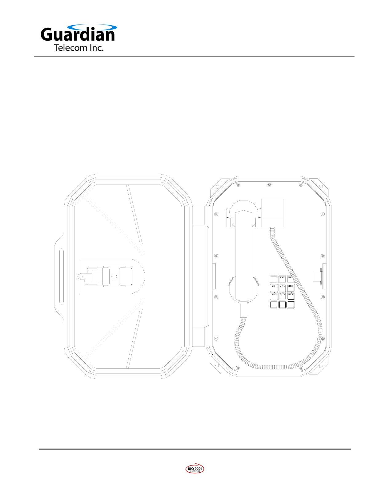
Overview
WP80 Waterproof 4X Telephone
Guardian’s WP80 offers maximum efficiency under extreme environmental conditions. The sturdy
urethane enclosure protects the internal circuitry against wind blown dust and rain, corrosion,
splashing and high pressure water.
The WP80 is approved with a CSA Type 4X rating, making it the ideal telephone for use in wet or
corrosive atmospheres such as chemical plants or offshore platforms.
Features
Enclosure
• Polyurethane body construction
• weatherproof and corrosion resistant
• spring loaded, locking hinged door
• tamper resistant faceplate screws
• steel mounting bracket – zinc dichromate plated and powder coated
Keypad
• Standard 3x4 matrix
Encapsulated Circuitry
• encapsulated circuit boards are resistant to corrosive agents
(e.g. H
S, SO2 and NH3) and environments with high humidity
2
Magnetic Reed Hook Switch
• No moving parts
Surge Arrestor and Field Replaceable Fuse
• Prevents damage to the electronic circuitry in the event of a high
voltage spike on the telephone line
Wall Mount
• Easily mounted on any sturdy vertical structure
Noise Reducing Microphone
• allows a high level of intelligibility in locations with high background
noise
Tone (DTMF) Operation
• factory set to tone (DTMF) dialing
• can be ordered set for pulse dialing or configured in the field
Armored Handset Cord
• withstands severe use
Hearing-Aid Compatible
• compatible with inductively coupled hearing-aid devices
Page 3
Page 4
Guardian Telecom Inc.
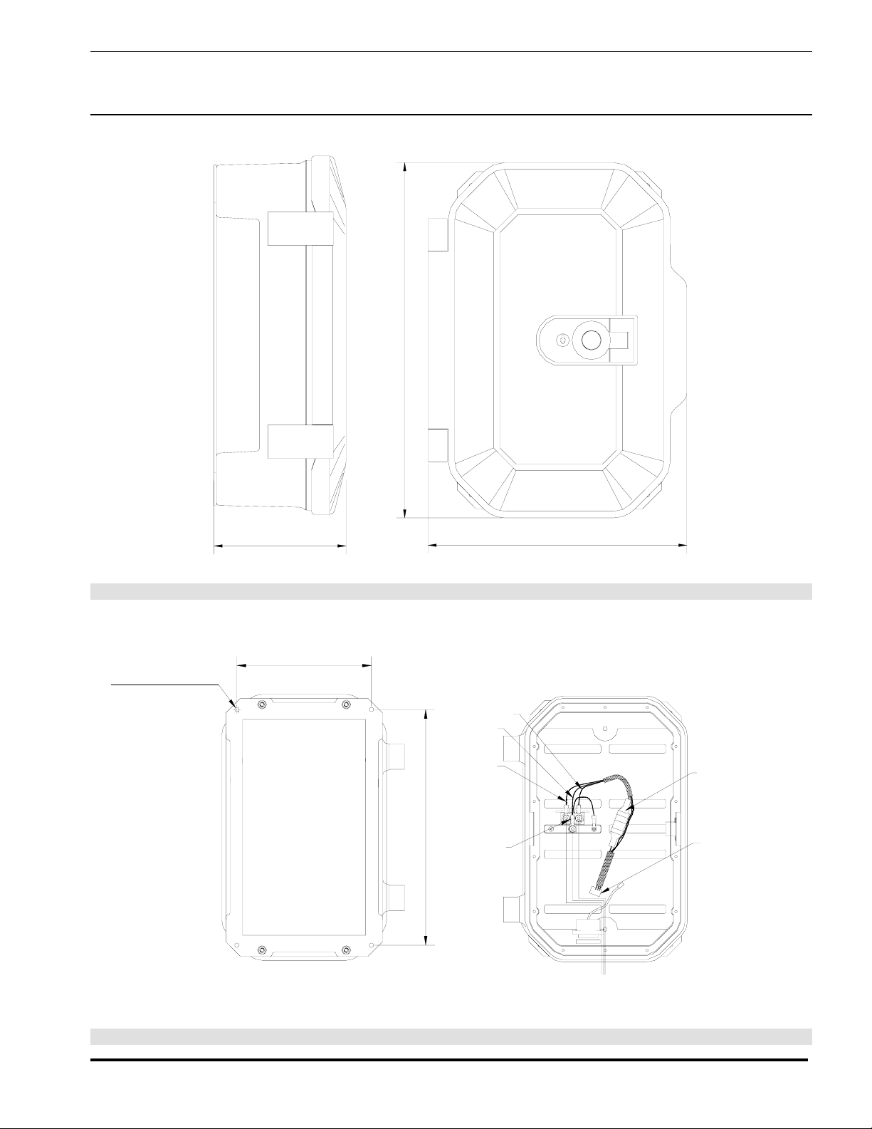
16.4" [417mm]
Installation and Operation
Model WP80
Ø0.265" [Ø7mm]
for #10 or M5
6.3" [160mm]
8.0" [203mm]
12.0" [305mm]
Figure 1 - Overall Dimensions
ORANGE
GREEN
2 WIRE
BLUE
SURGE
ARRESTOR
14.0" [355mm]
FUSE
CONNECT TO
CIRCUIT BOARD
HARNESS
TIP
RING
GROUND FROM EXCHANGE
BACK VIEW
Figure 2 - Installation
Page 4
Page 5

Guardian Telecom Inc.
Installation and Operation
Installing the WP80
• Follow all appropriate electrical codes and use only approved electrical
fittings for the installation.
• For waterproofing purposes apply Teflon tape to all glands and conduits.
• Choose a wall location that is free of obstructions and permits space for ½”
NPT conduit runs.
• Ensure mounting can support 16 lbs (7.3 kg) and any additional foreseeable
load.
• Ensure that none of the electrical connection circuits are live.
• Separate the faceplate from the housing by removing the two temporary,
factory installed screws and unplugging the wiring harness from the
faceplate.
• To change the Tone/Pulse setting to pulse, if required:
o Move the jumper from pins 1 & 2 of the Tone/Pulse connector to
pins 2 & 3.
o To change the setting back to tone move the jumper back to pins 1 & 2.
• Use the template provided or the mounting bracket to locate and drill holes
for mounting screws.
• Secure the unit to the wall.
• Bring cable into the enclosure through the conduit entrance and attach
individual wires from the exchange (Tip/Ring/Ground) to the surge arrestor,
(Tip & Ring are not polarity sensitive.). If a conduit hub is used, ensure it is
grounded to the ground stud.
• Plug the wiring harness back into the faceplate and secure the faceplate
using the tamper resistant screws and driver bit provided.
• Connect the telephone lines at the local exchange or demarcation block.
• Test the unit by making calls to and from another station.
Model WP80
See: Figure 1 - Overall
Dimensions.
Tip: The WP80 is factory
preset for DTMF tone.
See:.Figure 3 - Setting
Dialing Mode
Tip: Use ¼” or M8
screws to secure the unit
to the wall.
See: Figure 2 Installation
TONE/PULSE
JUMPER
Guardian Telecom Inc.
S/N:____________
Calgary, Canada
RIN-
HK
PHONE
TONE/
HANDSET
GER
SW
LINE
PULSE
Figure 3 - Setting Dialing Mode
Page 5
Page 6

Guardian Telecom Inc.
Maintenance
• The only field repair possible is setting the dialing mode and the
replacement of fuses. All other repairs or alterations must be carried out by
Guardian Telecom or an Authorized Service Depot. See Warranty and
Disclaimer for details.
Operation
• Once your Model WP80 Telephone has been properly installed and
energized, operation is identical to most other single line telephones.
Fuse Replacement
Installation and Operation
Model WP80
See: Installing the WP80
and Fuse Replacement
• Disconnect the telephone from Tip and Ring power supplied by the PABX
or central office before attempting to replace the fuse.
• Carefully remove the front cover assembly and separate from the housing
by disconnecting the harness plugs. NOTE that the handset and all
electronics are attached to the front plate.
• Replace fuse in fuse holder.
• Carefully replace the front plate and install all 14 screws. Do not over
tighten the cover screws, there is a flexible gasket between the cover and
the body. Excessive tightening of the screws deforms the gasket and
reduces the weather resistance of the set.
WARNING!
• Replace only with a 0.25 amp 3AG fast blow fuse. Failure to do so will void
the warranty.
• If, on reconnecting power, the fuse fails, check the telephone system
wiring. The fuse protects the Tip and Ring line from the telephone system.
It is usually powered at 48 volts DC and must not be connected to 120 volts
AC.
Tip: Use the drive bit for
tamper resistant screws
supplied with the
telephone
See:Figure 2 Installation
Page 6
Page 7

Guardian Telecom Inc.
Installation and Operation
Engineering Specifications
Electrical Performance
AUDIBLE RANGE FREQUENCY RESPONSE 300 - 3400 HZ
DIALING METHOD DTMF or 40/60 PULSE AT 10 PPS
TRANSMIT OBJECTIVE LOUDNESS RATING (TOLR) -38 +/- 3 dB
RECEIVE OBJECTIVE LOUDNESS RATING (ROLR) TYPICAL 50 +/- 3 dB
SIDE TONE OBJECTIVE LOUDNESS RATING (SOLR) TYPICAL 11 +/- 4 dB
RINGER OUTPUT >65 dB
FCC RINGER EQUIVALENCE NUMBER (REN) 0.8 B
SET IMPEDANCE 600 OHMS NOMINAL
MAXIMUM LOOP 15,000 FT (4,600 M) of 22 AWG COPPER
Model WP80
Electrical Requirements
RINGER SENSITIVITY 40 - 100 V, 16 - 25 HZ
LINE VOLTAGE 24 - 56 VDC
LOOP CURRENT 20 - 120 MA
CONNECTION METHOD SURGE ARRESTOR TERMINAL BLOCK
FUSE ¼ AMP 3AG FAST BLOW
Environmental
WEATHER AND CORROSION RESISTANT
TEMPERATURE -50
HUMIDITY 0 TO 100% RH
DUST RESISTANT FULL ENCLOSURE GASKET
Mechanical
HOOK SWITCH (CRADLE SWITCH) LIFE >1 000 000 OPERATIONS
BODY CONSTRUCTION POLYURETHANE
FACEPLATE POLYURETHANE
DIMENSIONS 16.4 x 12.0 x 6.3 INCHES (417 x 305 x 160 MM)
NET WEIGHT 16 LBS (7.3 KG)
Enclosure 4X
O
TO +50
O
C
HANDSET MATERIAL HIGH IMPACT ABS
MICROPHONE NOISE REDUCING ELECTRET
RECEIVER HEARING AID COMPATIBLE
STANDARD MOUNTING VERTICAL WALL
CONNECTIONS 1/2” NPT THREADED OPENINGS
HARDWARE MATERIAL STAINLESS STEEL
Page 7
Page 8

Guardian Telecom Inc.
Installation and Operation
Model WP80
Compliance
MILITARY STANDARDS MIL-STD 810E
WATERPROOF ENCLOSURE CSA TYPE 4X
Models and Options
• P6480 Model WP80 Weatherproof 4X Telephone
• P6481 Model WP81 Weatherproof 4X Telephone (Ringdown)
Accessories
• P7224 Potted ring detect relay, (internal to telephone)
• P7225 Weatherproof ring detect relay, (external to telephone)
• P7228 Potted off-hook detect relay, (internal to telephone)
• P7229 Weatherproof off-hook detect relay, (external to telephone)
• Loud Ringer
Page 8
Page 9

Guardian Telecom Inc.
Installation and Operation
Model WP80
Warranty
Guardian Telecom warrants your product to be free of defects in material and workmanship for a period
of one year. Guardian Telecom will repair or replace any defective unit that is under warranty
This warranty is null and void if any non-authorized modifications have been made to this product, or if
it has been subjected to misuse, neglect, or accident. This warranty covers bench repairs only; such
repairs must be made at Guardian Telecom or an authorized service depot. Guardian Telecom is not
responsible for costs incurred for on-site service calls, freight, or brokerage.
A return authorization must be obtained prior to warranty claims or repairs.
Disclaimer
The products covered by this manual are designed for use in Industrial Environments and/or Hazardous
Locations. Due to the range of possible applications for these instruments the manufacturer will not be
responsible for damages or losses of any kind suffered as a result of the use of this product, including
consequential damages.
Warning
For the purposes of installing the product and replacing fuses only this device may be opened and
reassembled by qualified personnel, following the instructions in the product manual.
Service Telephone Number
1-800-363-8010
Guardian Telecom provides a customer service telephone number which is toll-free within North
America. If you need assistance when installing or operating this product, please call the toll-free
telephone number between regular business hours (8:00AM-5:00PM), Mountain Standard Time. If you
are calling outside of regular business hours, please leave a detailed message, and a member of
Guardian Telecom’s Service Department will return your call as soon as possible. If your product
requires service, Guardian personnel will supply you with an RMA (return materials authorization)
number over the telephone or through our web site product return page. This number must be included
with your return address and the name of the person to contact.
Guardian Telecom Inc.
7552 - 10th Street N.E.
Calgary, Alberta, Canada T2E 8W1
Toll-free 1-800-363-8010
Ph. (403) 258-3100
Fax. (403) 253-4967
www.guardiantelecom.com
Feedback
Guardian Telecom continually strives to make reliable, durable, and easy to use products. If you, as an
installer or user of our equipment, have any suggestions for improvements to this or any of our products
or documents, including this manual, we would appreciate hearing from you.
Page 9
Page 10

Guardian Telecom Inc.
Guardian Product Return
Guardian products have been quality tested and are in full working order when
shipped from the factory, given the rugged nature of these products, shipping is not
expected to damage a unit. In the unlikely event of a malfunction, Guardian follows the
three step procedure below.
Step I - On-Site Correction
• The most common source of difficulties with a new product is improper installation
in one of two ways: incorrect wiring connections or connection to an incorrect
power source.
• Product wiring needs to be properly connected to the on-site wiring. Correct wiring
instructions are shown in the user manual included with the product.
• Connecting a telephone to a standard power source, rather than tip & ring, will
blow the telephone’s internal, user-replaceable fuse. In the event of fuse burn-out,
disconnect the telephone from the power source, replace the fuse, and reconnect
following the wiring diagrams provided with the product.
Installation and Operation
Model WP80
Step II - Return Materials Authorization (RMA)
• When a product has been installed following user manual instructions, and the unit
fails to operate, the user must contact Guardian Telecom to obtain authorization to
return the product. This can be done by done by completing a RMA form online at
www.guardiantelecom.com, or by calling the service telephone number given in
this manual.
• After providing information on the product, the owner and the nature of the
problem, Guardian will issue a RMA number, to be shown on documentation
returned with the product.
• In addition to the RMA number, shipping documents should include name, address
and telephone number of the owner along with contact information for the person
responsible for the repair and/or the user who identified the malfunction.
• (Where a product is being returled for repair from outside of Canada, customs
documentation must show the product’s serial number, date of export [date of
purchase], and a notation that the equipment is: “Canadian goods returning.”)
Step III - Factory Authorized Service
• Once received, each product is carefully inspected and tested. If the product is
under warranty, repairs are completed and the product returned to the owner,
generally within five working days of receipt by the factory.
• A product that has been subjected to misuse, neglect or accident or is beyond the
warranty period will be evaluated. The service department will provide the owner’s
representative with a repair cost estimate. Once approved, repairs are completed
and the product returned, generally within five working days.
Page 10
Page 11

Guardian Telecom Inc.
Notes:
Model No.
Part No.
Serial No.
Date of Purchase
Installation and Operation
Model WP80
Page 11
Page 12

Guardian Telecom Inc.
7552 - 10th Street N.E.
Calgary, Alberta, Canada T2E 8W1
Toll-free 1-800-363-8010
Ph. (403) 258-3100
Fax. (403) 253-4967
www.guardiantelecom.com
E-mail: sales@guardiantelecom.com
Industrial Communications Worldwide
© Guardian Telecom Inc. 2004
 Loading...