

Page 1

Industrial Communications Worldwide
VoIP Telephones
Setup & Configuration
P007402 Rev. B 120620 7/4/2012 2:36 PM
Ph: 403.258.3100 \ email:info@guardiantelecom.com \ www.guardiantelecom.com
7552 - 10th Street N.E. Calgary, Alberta, Canada T2E 8W1
Page 2

Guardian Telecom Inc. Setup & Configuration
VoIP Telephones
VoIP Setup & Configuration P007402 Rev. B
COPYRIGHT NOTICE:
© 2012, Guardian Telecom Inc., ALL RIGHTS RESERVED.
This manual and related materials are the copyrighted property of Guardian Telecom Inc. No part of this manual or related
materials may be reproduced or transmitted, in any form or by any means (except for internal use by licensed customers),
without prior express written permission of Guardian Telecom Inc.. This manual, and the products, software, firmware, and/or
hardware described in this manual are the property of Guardian Telecom Inc. provided under the terms of an agreement
between Guardian Telecom Inc. and the recipient of this manual, and their use is subject to that agreement and its terms.
DISCLAIMER: Except as expressly and specifically stated in a written agreement executed by Guardian Telecom Inc.,
Guardian Telecom Inc. makes no representation or warranty, express or implied, including any warranty or merchantability or
fitness for any purpose, with respect to this manual or the products, software, firmware, and/or hardware described herein, and
Guardian Telecom Inc. assumes no liability for damages or claims resulting from any use of this manual or such products,
software, firmware, and/or hardware. Guardian Telecom Inc. reserves the right to make changes, without notice, to this
manual and to any such product, software, firmware, and/or hardware.
OPEN SOURCE STATEMENT: Certain software components included in Guardian products are subject to the GNU General
Public License (GPL) and Lesser GNU General Public License (LGPL) “open source” or “free software” licenses. Some of this
Open Source Software may be owned by third parties. Open Source Software is not subject to the terms and conditions of the
Guardian COPYRIGHT NOTICE or software licenses. Your right to copy, modify, and distribute any Open Source Software is
determined by the terms of the GPL, LGPL, or third party, according to who licenses that software.
Software or firmware provided by Guardian that is unrelated to Open Source Software is copyrighted by Guardian, subject to
the terms of Guardian licenses, and may not be copied, modified, reverse-engineered, or otherwise altered without explicit
written permission from Guardian Telecom Inc.
TRADEMARK NOTICE: Guardian Telecom Inc. and the Guardian Telecom Inc. logos are trademarks of Guardian Telecom
Inc. Other product names, trademarks, and service marks may be the trademarks or registered trademarks of their respective
owners.
Toll-free 1-800-363-8010
Phone (403) 258-3100
Fax. (403) 253-4967
www.guardiantelecom.com
E-mail:
sales@guardiantelecom.com
Page 2
Page 3

Guardian Telecom Inc. Setup & Configuration
VoIP Telephones
IMPORTANT Installation Step
It is important to register this VoIP product with Guardian Telecom to ensure it has the
most current version of software and to receive notification of software updates.
Registering Your VoIP Product
To register your VoIP product send an email to info@guardiantelecom.com.
Be sure to include “Guardian VoIP Registration” in the subject field of your email.
Include the following information:
Company Name of End User (Req'd)
Address of End User (Optional)
Device Model (Req'd)
Serial Number (Req'd)
Date of purchase (Req'd)
Name of Supplier (Req'd)
Prime Contact name and e-mail (Req'd)
Secondary Contact name and e-mail (Optional)
Phone Info: (Optional)
It is very important that we receive e-mail contact information of the person responsible
for maintaining the installed Guardian Equipment, in order to ensure optimum
performance of the device.
Contact information will remain confidential and will not be used for third-party
marketing purposes.
Page 3
Page 4
Guardian Telecom Inc. Setup & Configuration
VoIP Telephones
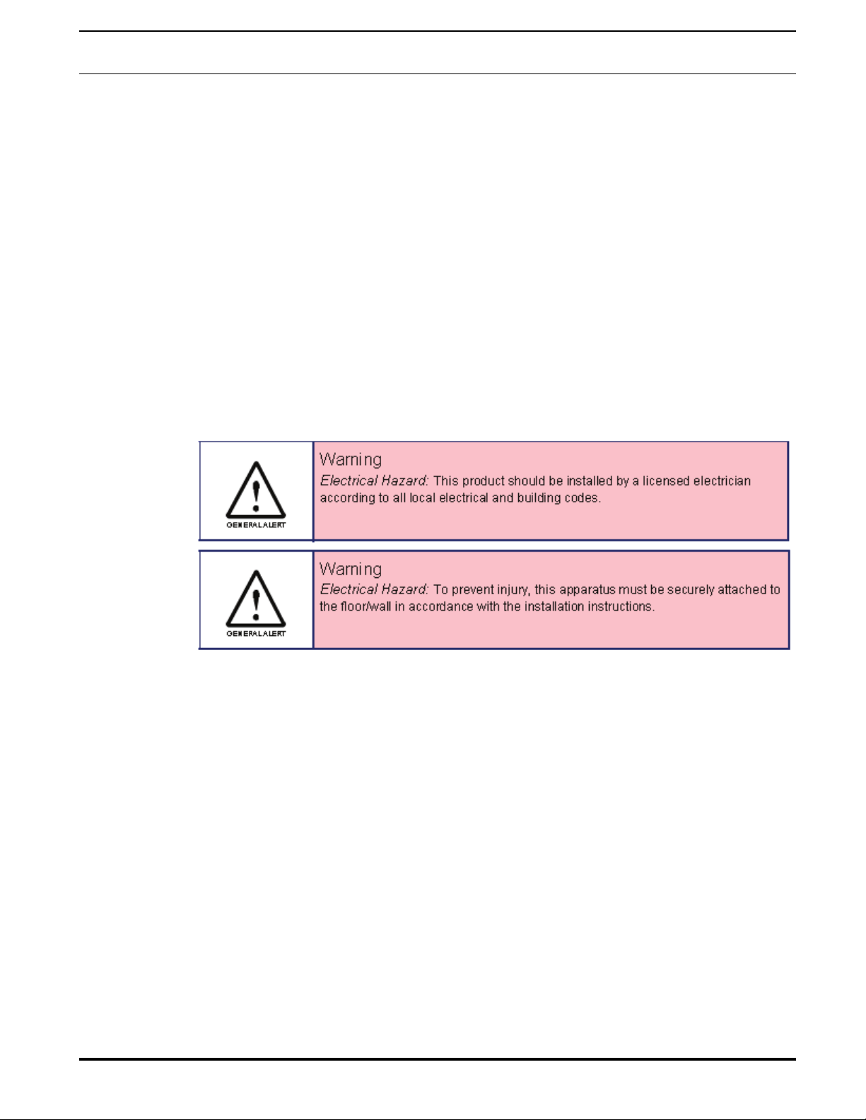
Important Safety Instructions
1. Read these instructions.
2. Keep these instructions.
3. Heed all warnings.
4. Follow all instructions.
5. Install in accordance with the manufacturer’s instructions.
6. Do not install near any heat sources such as radiators, heat registers, stoves, or other apparatus
(including amplifiers) that produce heat.
7. Only use attachments/accessories specified by the manufacturer.
8. Refer all servicing to qualified service personnel.
9. Prior to installation, consult local building and electrical code requirements.
Page 4
Page 5

Guardian Telecom Inc. Setup & Configuration
VoIP Telephones
Table of Contents
1. Typical System Installation ......................................................................................... 7
2. Operation.................................................................................................................... 7
3. Supported Protocols ...................................................................................................7
4. Supported SIP Servers............................................................................................... 7
5. Getting Started ...........................................................................................................8
6. Configure the Telephone Parameters......................................................................... 8
6.1. Telephone Web Page Navigation.................................................................... 9
6.2. Log in to the Configuration Home Page ........................................................ 10
6.3. Configure the Device Parameters .................................................................12
6.4. Configure the Network Parameters ............................................................... 14
6.5. Configure the SIP Parameters ......................................................................16
6.6. Configure the Nightringer Page..................................................................... 20
6.7. Configure the Audio Parameters ................................................................... 22
6.7.1. User-created Audio Files ...................................................................... 24
6.8. Configure the Event Parameters ................................................................... 26
6.9. Configure the Autoprovisioning Parameters.................................................. 30
6.10. Advanced Configuration (Debug) Page......................................................... 34
6.10.1. Reboot the Telephone .......................................................................... 36
7. Setting up a TFTP Server......................................................................................... 36
7.1. In a LINUX Environment ...............................................................................36
7.2. In a Windows Environment ........................................................................... 36
8. Discovery Process.................................................................................................... 37
8.1. Accessing webpage functionality without a browser .....................................37
8.2. RESET Switch............................................................................................... 37
8.3. Testing the hardware ....................................................................................37
9. Frequently Asked Questions..................................................................................... 39
10. Product Specifications ..............................................................................................41
Figures
Figure 1 - Typical Installation ..............................................................................................7
Figure 2 - Startup Screen.................................................................................................... 8
Figure 3 - Home Page....................................................................................................... 10
Figure 4 - Device Configuration Page ............................................................................... 12
Figure 5 - Network Configuration Page ............................................................................. 14
Figure 6 - SIP Configuration Page ....................................................................................16
Figure 7 - Nightringer Configuration Page......................................................................... 20
Figure 8 - Audio Configuration Page ................................................................................. 22
Figure 9 - Audacity 1 ......................................................................................................... 24
Figure 10 - Audacity 2 .......................................................................................................24
Figure 11 - WAV (Microsoft) signed 16 bit PCM................................................................ 25
Figure 12 - Event Configuration Page ............................................................................... 26
Figure 13 - Autoprovisioning Configuration Page.............................................................. 30
Figure 14 - Upgrade Firmware Page................................................................................. 32
Figure 15 - Advanced Configuration.................................................................................. 34
Page 5
Page 6

Guardian Telecom Inc. Setup & Configuration
VoIP Telephones
Tables
Table 1 - Factory Default Settings.......................................................................................8
Table 2 - Telephone Web Page Navigation......................................................................... 9
Table 3 - Home Page Overview ........................................................................................11
Table 4 - Device Configuration Parameters ......................................................................13
Table 5 - Network Configuration Parameters ....................................................................15
Table 6 - SIP Configuration Parameters............................................................................ 17
Table 7 - Nightringer Configuration Parameters................................................................ 21
Table 8 - Audio Configuration Parameters ........................................................................23
Table 9 - Event Configuration............................................................................................ 27
Table 10 - Autoprovisioning Configuration Parameters ..................................................... 31
Table 11 - Firmware Upgrade Parameters ........................................................................ 32
Table 12 - Advanced Configuration ................................................................................... 35
Table 13 - Command Interface Post Commands ..............................................................37
Acronyms
DHCP Server Dynamic Host Configuration Protocol
DHCPD Dynamic Host Configuration Protocol Daemon
DTMF Dual-tone Multi-frequency
HTTP Hypertext Transfer Protocol
IP Address Internet Protocol Address
LAN Local Area Network
LINUX Unix-like computer operating system
PBX Private Branch Exchange
PC Personal Computer
PCM Pulse-Code Modulation
PCMA Paired Carrier Multiple Access
PCMU Pulse Code Modulation mu-law
PoE Power over Ethernet
POST Power On Self Test
RIFF A short, repeated musical phrase
RTP Real-time Transport Protocol
RTP Port Real-time Transport Protocol port
AVP Audio Video Profile
SIP Session Initiation Protocol
TFTP Trivial File Transfer Protocol
URL Uniform Resource Locator
VoIP Voice Over Internet Protocol
WAV Waveform Audio File Format
WAVE Waveform Audio File Format
XML File Extensible Markup Language
Page 6
Page 7
Guardian Telecom Inc. Setup & Configuration
VoIP Telephones
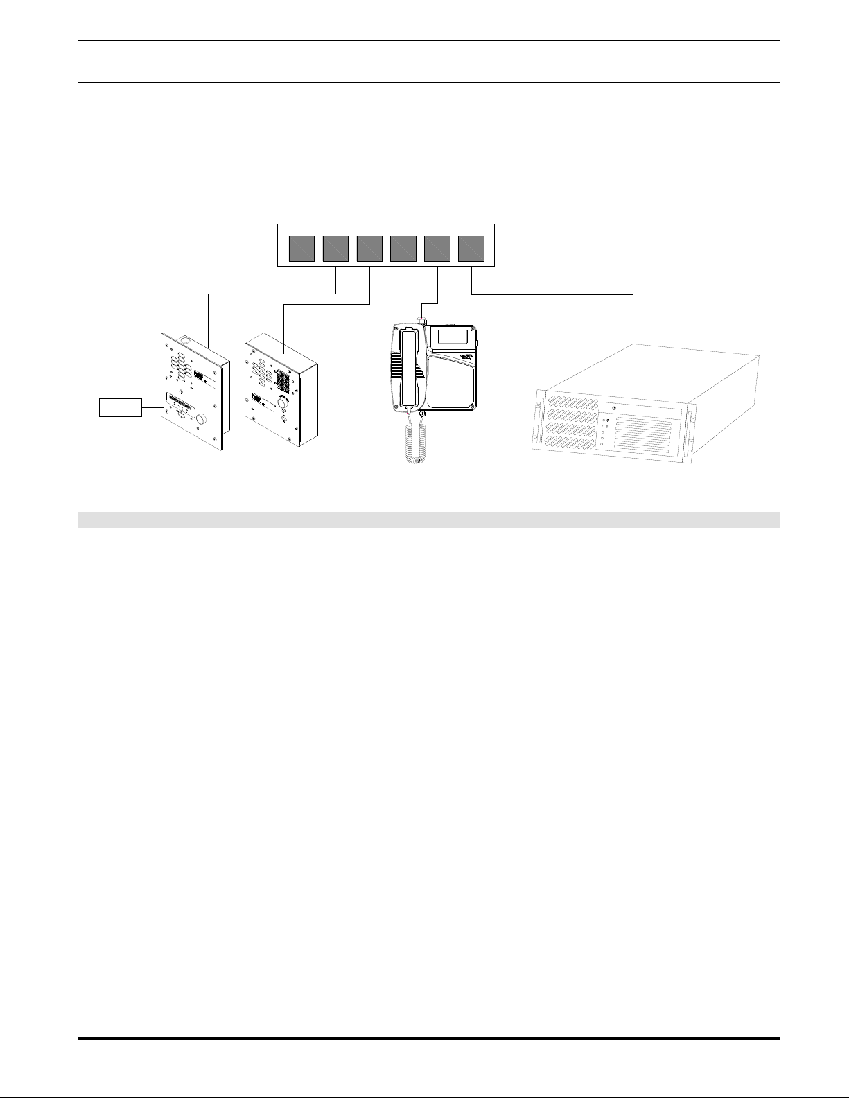
1. Typical System Installation
The Voice-over-IP (VoIP) Telephone is a Power-over-Ethernet (PoE 802.3af) and Voice-over-IP (VoIP) two-way
communications device that easily connects into existing local area networks (LANs) with a single cable connection. The
telephone is compatible with most SIP-based IP PBX servers that comply with SIP RFC 3261.
Figure 1 illustrates how VoIP Telephones can be installed as part of a VoIP phone system.
Generic PoE Hub
123456
EXTERNAL
DEVICES
L
A
N
1
L
A
N
2
A
L
A
R
M
Guardian VoIP Emergency Telephones Guardian VoIP Industrial Telephones IP PBX Server
Figure 1 - Typical Installation
2. Operation
Once your VoIP Telephone h
telephones.
as been properly installed and energized, operation is identical to most other single line
3. Supported Protocols
The VoIP Telephone with Keypad supports:
●SIP (Session Initiation Protocol)
●HTTP Web-based configuration
Provides an intuitive user inte
●DH
CP Client
Dynamicall
●TF
TP Client
Facilitates
●RT
P
cilitates autoprovisioning configuration values on boot
Fa
●Au
dio Encodings
PCMU (G.711
y assigns IP addresses in addition to the option to use static addressing.
hosting for the Autoprovisioning configuration file.
mu-law)
rface for easy system configuration and verification of a VoIP Telephone.
PCMA (G.711 A-law)
Packet Time 20 ms
4. Supported SIP Servers
As a SIP device, this product will operate with m
ost IP PBX servers.
Page 7
Page 8
Guardian Telecom Inc. Setup & Configuration
VoIP Telephones
5. Getting Started
The Installation manual provided with the telephone provides information on installing and connecting the device to the server.
This manual describes the steps required to customize the telephone to suit the individual’s preferences.
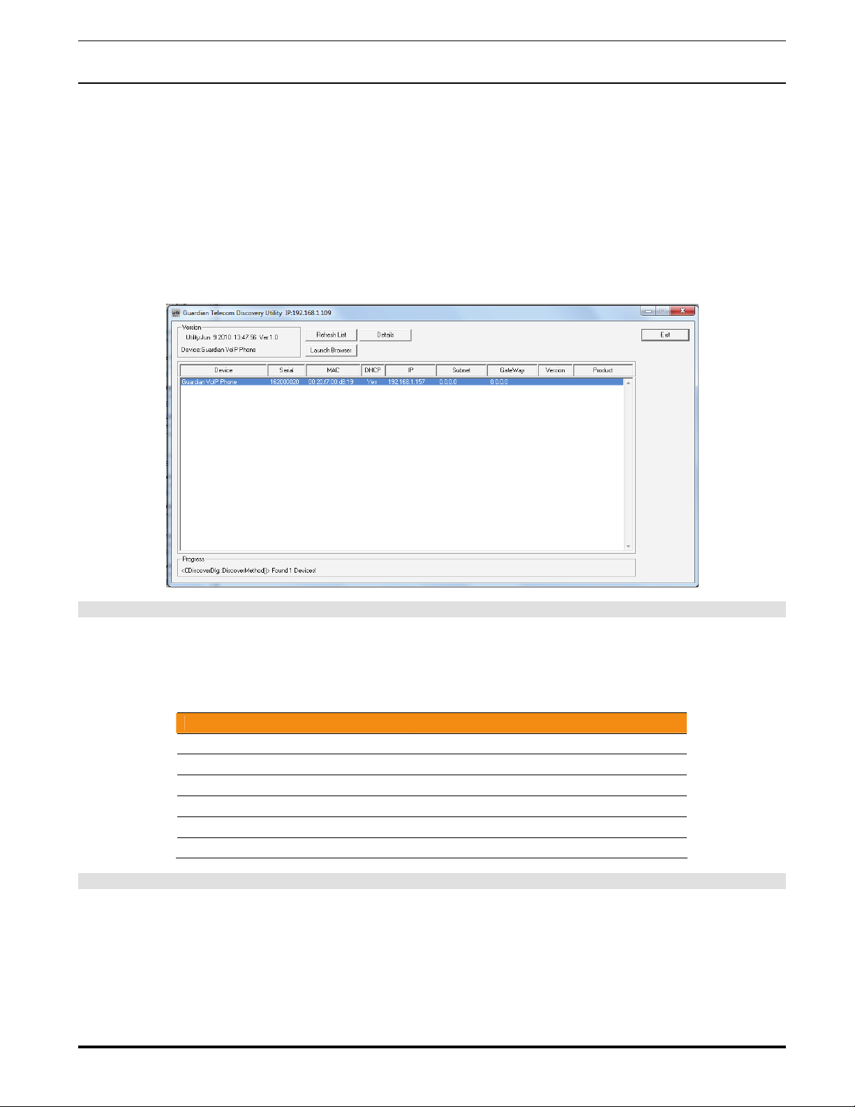
The Discovery Utility is supplied on a CD and needs to be installed manually.
To access a VoIP phone for programming:
• Install the Guardian Discovery Utility onto the network server or SIP server.
• Start the Utility by double clicking the icon.
• Click on “Refresh List”.
• Click on the device to be programmed to highlight it.
• Click on “Launch Browser”.
Figure 2 - Startup Screen
6. Configure the Telephone Parameters
To configure the Telephone online use a standard web browser.
All Telephones are initially configured with the following default IP settings:
Parameter Factory Default Setting
IP Addressing DHCP
IP Addressa 10.10.10.10
Web Access Username admin
Web Access Password admin
Subnet Maska 255.0.0.0
Default Gatewaya 10.0.0.1
Table 1 - Factory Default Settings
a. Default if there is not a DHCP server present.
When configuring more than one Telephone attach the Telephones to the network and configure one at a time to avoid IP
address conflicts.
Page 8
Page 9
Guardian Telecom Inc. Setup & Configuration
VoIP Telephones
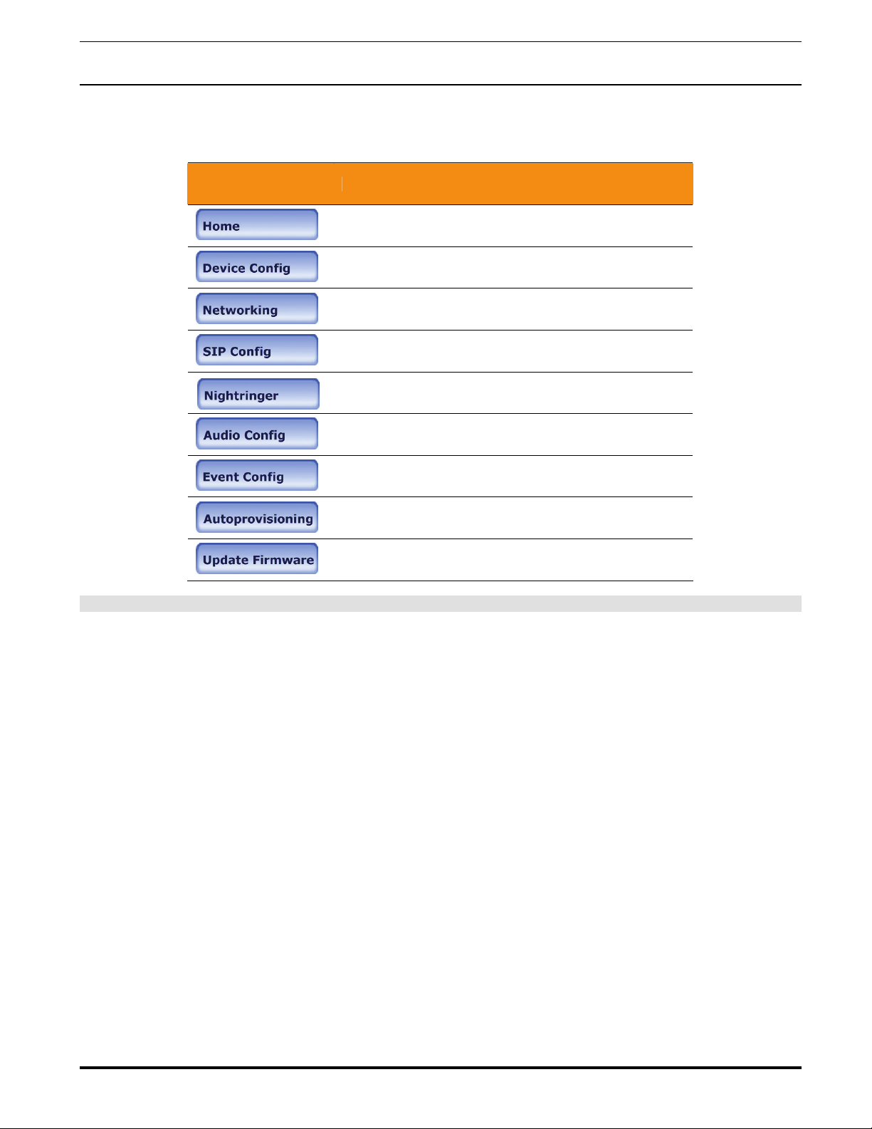
6.1. Telephone Web Page Navigation
Table 2 shows the navigation buttons that you will see on every Telephone web page.
Web Page Item Description
Link to the Home page.
Link to the Device Configuration page.
Link to the Networking page.
Link to the SIP Configuration page.
Link to the Nightringer Configuration page.
Link to the Audio Configuration page.
Link to the Event Configuration page.
Link to the Autoprovisioning Configuration page.
Link to the Update Firmware page.
Table 2 - Telephone Web Page Navigation
Page 9
Page 10
Guardian Telecom Inc. Setup & Configuration
VoIP Telephones
6.2. Log in to the Configuration Home Page
1. Open your browser to the Telephone’s IP address. If you do not know the IP address, you can use the “Discovery
Utility” to detect all VoIP devices on the network. When opened the Discovery Utility scans the network for VoIP devices,
specifically Guardian VoIP devices. Individually select the device and launch the browser. Another method to obtain the IP
address is to press the RESET switch for approximately one second. The phone will speak the address through the
handset earpiece. The physical location of a telephone can be determined by comparing either the MAC Address, IP
Address or Serial Number shown on the Discovery Utility screen with the information on the unit.
Note: If the network does not have access to a DHCP server, the device will default to an IP address of
10.10.10.10.
Note: Make sure that the PC is on the same IP network as the Telephone.
2. When prompted, use the following default Web Access Username and Web Access Password to access the Home
Page (Figure 3):
Web Access Username: admin
Web Access Password: admin (Iower case)
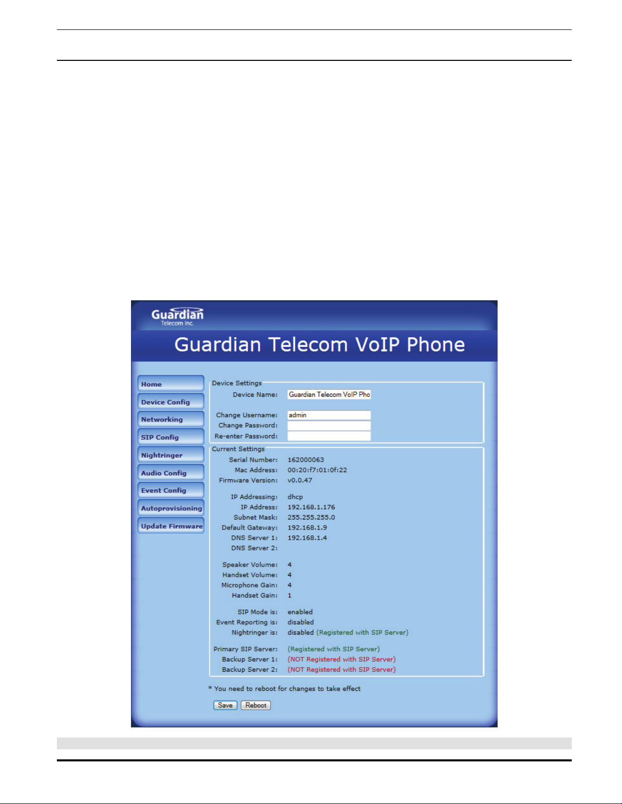
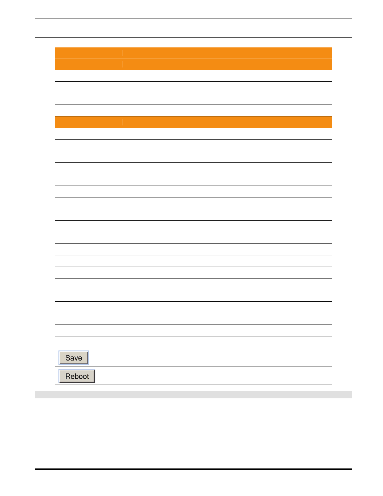
3. On the Home Page, review the setup details and navigation buttons described in Table 3.
Note: The Screen Captures shown are only examples; refer to the tables for definitions.
Figure 3 - Home Page
Page 10
Page 11
Guardian Telecom Inc. Setup & Configuration
VoIP Telephones
Web Page Item Description
Device Settings
Device Name: Shows the device name.
Change Username: Type in this field to change the username.
Change Password: Type in this field to change the password.
Re-enter Password: Type the password again in this field to confirm the new password.
Current Settings
Serial Number: Shows the device serial number.
Mac Address: Shows the device Mac address.
Firmware Version: Shows the current firmware version.
IP Addressing:
IP Address: Shows the current IP address.
Subnet Mask: Shows the current subnet mask address.
Default Gateway: Shows the current default gateway address.
DNS Server 1: Shows the current DNS Server 1 address.
DNS Server 2: Shows the current DNS Server 2 address.
Speaker Volume: Shows the current speaker volume level.
Handset Volume: Shows the current handset volume level.
Microphone Gain: Shows the current microphone gain level.
Handset Gain: Shows the current handset gain level.
SIP Mode is: Shows the current SIP Mode status.
Event Reporting is: Shows the current Event Reporting status.
Nightringer is: Ringtone broadcast when enabled and extension is called.
Primary SIP Server: Primary SIP Server
Backup Server 1: Redundant SIP Server “1”
Backup Server 2: Redundant SIP Server “2”
Shows the current IP addressing setting (DHCP or static).
Click the Save button to save your configuration settings.
Note: You need to reboot for changes to take effect.
Click on the Reboot button to reboot the system.
Table 3 - Home Page Overview
Page 11
Page 12
Guardian Telecom Inc. Setup & Configuration
VoIP Telephones
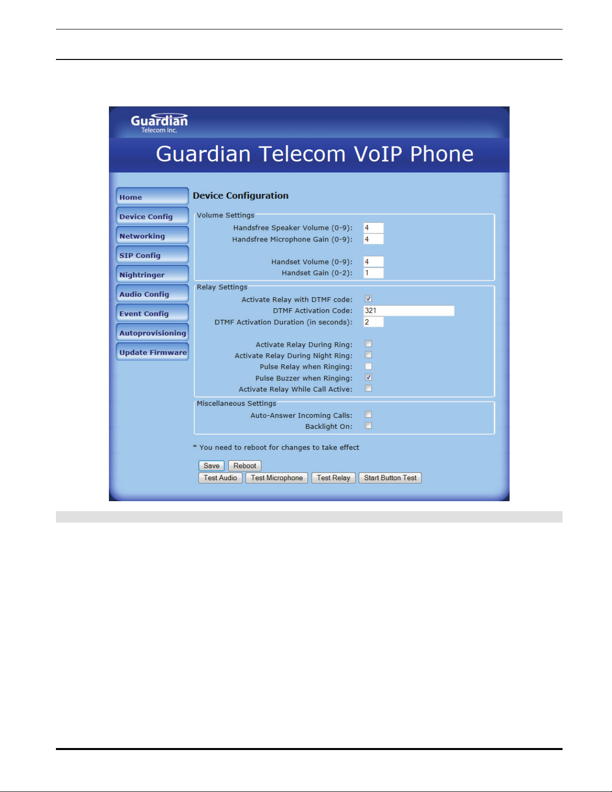
6.3. Configure the Device Parameters
1. Click the Device Configuration button to open the Device Configuration page. See Figure 4.
Figure 4 - Device Configuration Page
2. On the Device Configuration page, you may enter values for the parameters indicated in Table 4.
3. After changing the parameters, click the Save button.
Page 12
Page 13

Guardian Telecom Inc. Setup & Configuration
VoIP Telephones
Web Page Item Description
The volume settings describe the volume set on reboot. The user can change the
Volume Settings
Hands Free Speaker Volume:
Hands Free Microphone Gain:
Handset Volume:
Handset Gain:
Relay Settings
Activate Relay with DTMF Code:
DTMF Activation Code: This 25 character field can be used a set a DTMF code used to activate the relay.
DTMF Activation Duration (in
seconds):
Activate Relay During Ring:
Activate Relay During Night Ring:
Pulse Relay when Ringing:
Pulse Buzzer when Ringing:
Activate Relay While Call Active:
Miscellaneous Settings
Auto-Answer Incoming Calls:
Backlight On:
This button will activate the relay for the DTMF activation Duration (in seconds).
volume by using the up and down arrows, but this change is temporary and the
volume will be reset when the device is rebooted.
The speaker volume sets the initial volume of the device on boot. Valid values are 0-9.
Test the speaker volume using the ‘Test Audio’ button below. Saving changes to the
speaker volume will take effect immediately (it does not require a restart).
The microphone gain sets the initial input gain of the on board microphone. Valid
values are 0-9. Test the speaker volume using the ‘Test Microphone’ button below.
Saving changes to the speaker volume will take effect immediately (it doesn’t require a
restart).
The handset volume sets the initial volume of the handset on boot. Valid values are 0-
9. Saving changes to the handset volume will take effect immediately (it does not
require a restart).
The range of the handset gain is limited by the hardware and there are only three
volume levels available (low, medium, and high).
When this option is enabled, the device will activate the relay when it receives a DTMF
code (rfc2833).
When the relay is activated with a DTMF code, it will remain active for this duration in
seconds. Valid values are 1-9.
NOTE: A DTMF activation of 0 will toggle the relay indefinitely or until the activation
code is sent again.
When this option is enabled, the relay will activate when
the device has received a call and is playing a ringtone.
When this option is enabled, the relay will activate when
the device has received a call to the night ring extension.
When a “ring” is present the relay will pulse with a cadence of 2 seconds on, 3
seconds off.
When a “ring” is present the internal ringer will pulse with a cadence of 2 seconds on,
3 seconds off.
When this option is enabled, the relay will activate when a call is established with
another SIP device. It will remain active for the duration of the call.
When this option is enabled, the device will automatically answer incoming calls.
When the handset is on hook, the call will be established using the hands free speaker
and microphone.
This option sets the normal state of the backlight after the device has booted.
This button will play an audio test message and can be used to test the volume level.
When this button is pressed the device will record 3 seconds of audio, beep, and then
play back the recorded audio. This can be used to test the microphone gain level.
When this button is toggled, it will put the device into button test mode. In this mode,
the handset or hands free speaker will play an audio file when a button is pressed on
the device. For normal keypad input (keys 0-9) it will speak the associated file from the
audio configuration page. For the other keypad keys, (*, #, any other function keys) it
will play a DTMF tone while the button is depressed. The button press mode will time
out after 60 seconds.
Click the Save button to save your configuration settings.
Note: You need to reboot for changes to take effect.
Click on the Reboot button to reboot the system.
Table 4 - Device Configuration Parameters
Page 13
Page 14

Guardian Telecom Inc. Setup & Configuration
VoIP Telephones
6.4. Configure the Network Parameters
1. Click the Networking button to open the Network Configuration page (Figure 5).
Figure 5 - Network Configuration Page
2. On the Network Configuration page, enter values for the parameters indicated in Table 5.
3. After changing the parameters, click Save Settings. This updates the changed parameters and reboots the Telephone
if appropriate.
4. Connect the Telephone to the target network.
5. From a computer on the same network as the Telephone, open a browser with the new IP address of the Telephone.
Page 14
Page 15

Guardian Telecom Inc. Setup & Configuration
VoIP Telephones
Web Page Item Description
Stored Network Settings Shows the settings stored in non-volatile memory.
This setting is used to configure the device to use the static IP address
configured below or to fetch its address from a DHCP server on the network.
IP Addressing:
IP Address: The IPV4 static IP address in standard dotted decimal notation.
Subnet Mask: The IPV4 routing prefix in standard dotted decimal notation.
When the device is plugged into a network without a DHCP server, it will
request an address 12 times over the course of 60 seconds before it will fall
back on the last known good DHCP address, or if it has never had a DHCP
address, to the stored static IP address (by default 10.10.10.10).
Default Gateway:
DNS Server 1:
DNS Server 2:
Current Network Settings Shows the current network settings.
IP Address: Shows the current Static IP address.
Subnet Mask: Shows the current Subnet Mask address.
Default Gateway: Shows the current Default Gateway address.
DNS Server 1: Shows the current DNS Server 1 address.
DNS Server 2: Shows the current DNS Server 2 address.
This is the node to go to when an IP address doesn’t match any routes in the
routing table. This requires standard quad-dotted decimal notation.
The DNS server configuration is used to setup the primary and secondary name
servers for the network. These use standard dotted decimal notation.
Click the Save button to save your configuration settings.
Note: You need to reboot for changes to take effect.
Click on the Reboot button to reboot the system.
Table 5 - Network Configuration Parameters
Page 15
Page 16

Guardian Telecom Inc. Setup & Configuration
VoIP Telephones
6.5. Configure the SIP Parameters
1. Click SIP Config to open the SIP Configuration page (Figure 6).
Note: Guardian VoIP telephones are compatible with most SIP servers.
Figure 6 - SIP Configuration Page
2. On the SIP Configuration page, enter values for the parameters indicated in Table 6.
3. After changing the parameters, click Save Settings
Page 16
Page 17

Guardian Telecom Inc. Setup & Configuration
VoIP Telephones
Table 6 - SIP Configuration Parameters
Web Page Item Description
When this option is enabled, the device will initialize the SIP engine
Enable SIP Operation:
SIP Settings
SIP Server
Backup SIP Server 1:
Backup SIP Server 2:
Remote SIP Port:
Local SIP Port:
Outbound Proxy:
and try to register with a SIP server or listen for incoming SIP
connections.
The SIP server is used to set the address (in dotted decimal
notation or as a canonical name) of the SIP registrar. This field can
accept canonical names of up to 255 characters in length.
The SIP server is used to set the address (in dotted decimal
notation or as a canonical name) of the SIP registrar. This field can
accept canonical names of up to 255 characters in length.
The SIP server is used to set the address (in dotted decimal
notation or as a canonical name) of the SIP registrar. This field can
accept canonical names of up to 255 characters in length.
The Remote SIP Port is used to set the port number that the SIP
registrar uses for SIP traffic.
The Local SIP Port is used to set the port number this device will
use to listen for and transmit SIP traffic.
The Outbound Proxy Port is an optional field only filled in if a Proxy
server is used for SIP communications. It is used to set the port
number of the Proxy Server.
Outbound Proxy Port: Type the Outbound Proxy Port number (8 character limit).
SIP User ID:
Authenticate ID:
Authenticate Password:
Register with a SIP Server:
Re-registration Interval (in
seconds):
Unregister on Reboot:
The SIP User ID is the user part of a SIP address, generally this is
the extension number of the device.
The Authenticate Password is the password used for authentication
by the SIP server. If authentication is not configured on the SIP
server, this field should be blank.
The Authenticate Password is the password used for authentication
by the SIP server. If authentication is not configured on the SIP
server, this field should be blank.
When this option is enabled, the device will try to register with the
SIP server and credentials (given above) on boot. When the device
has successfully registered with a SIP server, it will show its status
at the top of the page. When this option is disabled, the device will
operate in point to point (P2P) mode. In this mode, the device can
connect to other SIP devices without using a SIP server as an
intermediary. This option only exists when using the speed dial
option on the button configuration page. Instead of putting an
extension in these fields, use a IP address.
Note: Some phones do not support placing or receiving calls to a
device rather than a SIP server.
The re-registration interval determines how often the device will
attempt to re-register with the SIP server. Valid values are 1003600 seconds. Some SIP servers may request a device register
more or less often than the value configured here.
If Unregister on Reboot is checked, this device will attempt to send
a remove all register request to the SIP server upon booting. Please
note that if the SIP server does not support this unregister request,
it may cause some problems.
Page 17
Page 18

Guardian Telecom Inc. Setup & Configuration
VoIP Telephones
Autodial Settings
Keypad AD
ID:
Ringdown Settings
Ringdown
ID:
Misc Settings
RTP Port (even) :
Play Button Tone:
Enter the speed dial extension that is to be used when the user
presses the Ml button.
Password for Keypad AD extension. If authentication is not
configured on the SIP server, this field should be blank.
If used the telephone will autodial that extension after handset has
been taken off-hook.
Password for Ringdown extension. If authentication is not
configured on the SIP server, this field should be blank.
The RTP Port field is used to set the port pair that this device will
use for listening for and transmitting RTP and RTCP traffic. This
field sets the RTP port. This field +1 sets the RTCP port. Per the
RFCS55O specification, the RTP port should be even, but an odd
port number is allowed.
When selected, you will hear a button tone when a keypad button is
pressed.
Click the Save button to save your configuration settings.
Note: You need to reboot for changes to take effect.
Click on the Reboot button to reboot the system.
Page 18
Page 19

Guardian Telecom Inc. Setup & Configuration
VoIP Telephones
THIS PAGE INTENTIONALLY LEFT BLANK
Page 19
Page 20

Guardian Telecom Inc. Setup & Configuration
VoIP Telephones
6.6. Configure the Nightringer Page
Click the Nightringer button to open the Nightringer Configuration page (Figure 7).
On the Nightringer Configuration page you may enter values for the parameters indicated in Table 7.
Figure 7 - Nightringer Configuration Page
Page 20
Page 21

Guardian Telecom Inc. Setup & Configuration
VoIP Telephones
Web Page Item Description
When the nightringer is enabled, the device will attempt to register a
Enable Nightringer:
Nightringer Settings
second extension with the SIP server. Any calls made to this extension
will play a ringtone.
SIP Server:
Remote SIP Port: Type the Remote SIP Port number (default 5060) (8 character limit).
Local SIP Port:
User ID:
Authenticate ID:
Authenticate Password:
Re-registration Interval (in
seconds):
Type the SIP server represented as either a numeric IP address in
dotted decimal notation.
Type the Local SIP Port number (default 5060)
(8 character limit).
Note: This value cannot be the same as the Local SIP Port
found on the SIP Configuration Page.
Type the User ID (up to 64 alphanumeric characters).
Type the Authenticate ID (up to 64 alphanumeric characters).
Type the Authenticate Password (up to 64 alphanumeric characters).
Type the SIP Registration lease time in minutes (default is 60 minutes)
(8 character limit). Re-registration Interval (in seconds).
Click the Save button to save your configuration settings.
Note: You need to reboot for changes to take effect.
Click on the Reboot button to reboot the system.
Table 7 - Nightringer Configuration Parameters
Page 21
Page 22

Guardian Telecom Inc. Setup & Configuration
VoIP Telephones
6.7. Configure the Audio Parameters
1. Click Audio Config to open the Audio Configuration page (Figure 8).
Figure 8 - Audio Configuration Page
Page 22
Page 23

Guardian Telecom Inc. Setup & Configuration
VoIP Telephones
The Audio Configuration page is used to add custom audio to the board. User uploaded audio will take precedence over the
audio files shipped with the Telephone.
2. On the Audio Configuration page, enter values for the parameters indicated in Table 8.
Note: Each entry on the Audio Configuration page replaces one of the stock audio files on the board. When the input box
displays the word default, the Telephone is using the stock audio file. If that file is replaced with a user file, it will display the
uploaded filename.
Web Page Item Description
Audio Files
The name of the audio configuration option is the same as the
spoken audio that plays on the board.
'0' corresponds to the spoken word “zero.”
'1' corresponds to the spoken word “one.”
'2' corresponds to the spoken word “two.”
0-9:
Dot: Corresponds to the spoken word “dot.” (24 character limit)
Audio test:
Page tone:
Your IP Address is:
Rebooting: Corresponds to the spoken word “Rebooting” (24 character limit).
Restoring default:
Ringback Tone:
Ring tone: Tone that plays when the device is ringing.
Night Ring:
'3' corresponds to the spoken word “three.”
'4' corresponds to the spoken word “four.”
'5' corresponds to the spoken word “five.”
'6' corresponds to the spoken word “six.”
'7' corresponds to the spoken word “seven.”
'8' corresponds to the spoken word “eight.”
'9' corresponds to the spoken word “nine.”
Corresponds to the message “This is the Guardian IP telephone
test message...” (200 character limit)
Corresponds to a simple tone that is unused by default (24
character limit).
Corresponds to the message “Your IP address is...” (24 character
limit).
Corresponds to the message “Restoring default” (24 character
limit).
This is the ringback tone that plays when calling a remote extension
(24 character limit).
When the nightringer is enabled, the device will attempt to register a
second extension with the SIP server. Any calls made to this
extension will play a ringtone.
Click the Browse button to search for files.
Click the Play button to hear the current message.
Click the Delete button to empty the box.
Click the Save button to save your settings.
Table 8 - Audio Configuration Parameters
Page 23
Page 24

Guardian Telecom Inc. Setup & Configuration
VoIP Telephones
6.7.1. User-created Audio Files
User created audio files should be saved in the following format:
RIFF (little-endian) data, WAVE audio, Microsoft PCM, 16 bit, mono, 8000 Hz
You can use the free utility Audacity to convert audio files into this format. See Figure 9 through Figure 11.
Figure 9 - Audacity 1
Figure 10 - Audacity 2
Page 24
Page 25

Guardian Telecom Inc. Setup & Configuration
VoIP Telephones
When you export an audio file with Audacity, save the output as:
• WAV (Microsoft) signed 16 bit PCM.
Figure 11 - WAV (Microsoft) signed 16 bit PCM
Page 25
Page 26

Guardian Telecom Inc. Setup & Configuration
VoIP Telephones
6.8. Configure the Event Parameters
Click the Event Config button to open the Event Configuration page (Figure 12).
The Event Configuration page specifies a remote server that can be used to receive HTTP POST events when actions
take place on the board.
Figure 12 - Event Configuration Page
Table 9 shows the web page items on the Event Configuration page.
Page 26
Page 27

Guardian Telecom Inc. Setup & Configuration
VoIP Telephones
Table 9 - Event Configuration
Web Page Item Description
Enable Event
Generation:
Remote Event
Server
Remote Event Server
IP:
Remote Event Server
Port:
Remote Event Server
URL:
Events Examples
Enable Button
Events:
When this option is selected the device will initialize the event generation engine. This mechanism
can be used to send xml formatted http POST packets to an external server in response to triggers
in the operation of the device.
This is the address of the remote TCP server for receiving POST events. This field can accept
addresses in dotted decimal notation or canonical names of up to 64 characters in length.
The Remote Event Server Port is used to set the port number that the remote server is listening on.
POST requests have to be sent to a target script at the given IP address. This field defaults to
‘xml_engine’ and can accept up to 127 characters.
When this option is enabled, an event will be sent to the remote server
every time a button is pressed.
POST xmlparse_engine HTTP/1 .1
Host: 10.0.3.79
User-Agent: Guardian 1.0.0
Content-Length: 196
Content-Type: application/x-www-form-urlencoded
<7xml version=” 1.0” encoding=”lSO-8859-1 “7>
<guardian NAME=GuardianVoIP Device MAC=’0020f70015b6’>
<event,.BUTTONdevent>
</guardian>
Enable Call Active
Events:
Enable Call
Terminated Events:
When this option is enabled, an event will be sent to the remote server
when a call becomes active.
POST xmlparse_engine HTTP/1 .1
Host: 10.0.3.79
User-Agent: Guardian 1.0.0
Content-Length: 201
Content-Type: application/x-www-form-urlencoded
<7xml version=’l .0,’ encoding=’lSO-8859-1 ‘7>
<guardian NAME=Guardian VoIP Device MAC=’0020f70015b6’>
<event>CALL_ACTlVEdeient>
</guardian>
When this option is enabled, an event will be sent to the remote server when a call is terminated.
POST xmlparse_engine HTTP/1 .1
Host: 10.0.3.79
User-Agent: Guardian 1.0.0
Content-Length: 205
Content-Type: application/x-www-form-urlencoded
<7xml version=”l .0,’ encoding=”ISO-8859-1 “7>
<guardian NAME=’Guardian VoIP Device MAC=’0020f70015b6’>
<event>CALL_TERMI NATEDdevent>
</guardian>
Page 27
Page 28

Guardian Telecom Inc. Setup & Configuration
VoIP Telephones
Enable Relay
Activated Events:
Enable Relay
Deactivated Events:
Enable Ring Events:
Enable Night Ring
Events:
Enable Power On
Events:
When this option is enabled, an event will be sent to the remote server
when the relay is activated.
POST xmlparse_engine HTTP/1 .1
Host: 10.0.3.79
User-Agent: Guardian 1.0.0
Content-Length: 234
Content-Type: application/x-www-form-urlencoded
<7xml version=”l .0” encoding=”ISO-8859-1 “7>
<guardian NAME=’Guardian VoIP Device’ MAC=’0020f70015b6’>
<event>RE LAY_ACTI VATEDdevent>
</guardian>
When this option is enabled, an event will be sent to the remote server
when the relay is deactivated.
POST xmlparse_engine HTTP/1 .1
Host: 10.0.3.79
User-Agent: GuardianDatall .0.0
Content-Length: 234
Content-Type: application/x-www-form-urlencoded
<7xml version=” 1.0” encoding=”lSO-8859-1 “7>
<guardian NAME=’Guardian VoIP Device’ MAC=’0020f70015b6’>
<event>RELAY_DEACTIVATED</event>
</guardian>
When this option is enabled, an event will be sent to the remote server
when the device starts playing a ringtone.
POST xmlparse_engine HTTP/1 .1
Host: 10.0.3.79
User-Agent: Guardian 1.0.0
Content-Length: 197
Content-Type: application/x-www-form-urlencoded
<7xml version=”l .0” encoding=”ISO-8859-1 “7>
<guardian NAME=’Guardian VoIP Device’ MAC=’0020f70015b6’>
<event>Rl NGI NG.</event>
</guardian>
When selected, there is a notification when the device receives a night ring.
POST xmlparse engine HTTP/1.1
Host: 10.0.3.79
User-Agent: GuardianData/1 .0.0
Content-Length: 234
Content-Type: application/x-www-form-urlencoded
<?xml version=°1.0° encoding=°ISO-8859-1°?>
<guardian NAME= ‘Guardian VOIP Device’
MAC=’ 002 0f70015b6 ‘>
tIGHTkILJGI tG /vnt>
/ guardian>
When this option is enabled, an event will be sent to the remote server
when the dice powers up.
POST xmlparse_engine HTTP/1 .1
Host: 10.0.3.79
User-Agent: Guardian 1.0.0
Content-Length: 197
Content-Type: application/x-www-form-urlencoded
<‘?xml version=”l .0,’ encoding=”ISO-8859-1 “7>
<guardian NAME=’Guardian VoIP Device’ MAC=’0020f70015b6’>
eve nt > P 0 WE RO N <eve nt>
</guardian>
Page 28
Page 29

Guardian Telecom Inc. Setup & Configuration
VoIP Telephones
Enable General
Purpose Input 1:
Enable General
Purpose Input 2:
Enable General
Purpose Input 3:
Enable General
Purpose Input 4:
Enable 60 Second
Heartbeat Events:
When this option is enabled, an event will be generated when a change is seen on the one of the
opto-isolated input lines
POST xmlparse_engine HTTP/1 .1
Host: 10.0.3.79
User-Agent: GuardianDatall .0.0
Content-Length: 197
Content-Type: application/x-www-form-urlencoded
<7xml version=” 1.0” encoding=”lSO-8859-1 “7>
<guardian NAME=’Guardian VoIP Device’ MAC=’0020f70015b6’>
<event>INPUT1</event>
</guardian>
When this option is enabled, an event will be generated when a change is seen on the one of the
opto-isolated input lines
POST xmlparse_engine HTTP/1 .1
Host: 10.0.3.79
User-Agent: Guardian 1.0.0
Content-Length: 197
Content-Type: application/x-www-form-urlencoded
<‘?xml version=”l .0” encoding=”ISO-8859-1 “7>
<guardian NAME=’Guardian VoIP Device’ MAC=’0020f70015b6’>
<event>l NPUT2.</event>
</guardian>
When this option is enabled, an event will be generated when a change is seen on the one of the
opto-isolated input lines.
POST xmlparse_engine HTTP/1 .1
Host: 10.0.3.79
User-Agent: Guardian 1.0.0
Content-Length: 197
Content-Type: application/x-www-form-urlencoded
<‘?xml version=”l .0,’ encoding=”ISO-8859-1 “7>
<guardian NAME=’Guardian VoIP Device MAC=’0020f70015b6’>
<event>l NPUT3.</event>
</guardian>
When this option is enabled, an event will be generated when a change is seen on the one of the
opto-isolated input lines
POST xmlparse_engine HTTP/1 .1
Host: 10.0.3.79
User-Agent: Guardian 1.0.0
Content-Length: 197
Content-Type: application/x-www-form-urlencoded
<‘?xml version=”l .0” encoding=”ISO-8859-1 “7>
<guardian NAME=’Guardian VoIP Device’ MAC=’0020f70015b6’> <event>l NPUT4</event>
</guardian>
When this option is enabled, an event will be sent to the remote server every 60 seconds.
POST xmlparse_engine HTTP/1 .1
Host: 10.0.3.79
User-Agent: GuardianDatall .0.0
Content-Length: 199
Content-Type: application/x-www-form-urlencoded
<7xml version=” 1.0” encoding=”lSO-8859-1 “7>
<guardian NAME=’Guardian VoIP Device’ MAC=’0020f70015b6’> <event>HEARTBEAT</event>
</guardian>
Click the Save button to save your configuration settings.
Note: You need to reboot for changes to take effect.
Click Test Event to test the event.
Click on the Reboot button to reboot the system.
Page 29
Page 30

Guardian Telecom Inc. Setup & Configuration
VoIP Telephones
6.9. Configure the Autoprovisioning Parameters
1. Click the Autoprovisioning button to open the Autoprovisioning Configuration page (Figure 13).
Figure 13 - Autoprovisioning Configuration Page
Page 30
Page 31

Guardian Telecom Inc. Setup & Configuration
VoIP Telephones
2. On the Autoprovisioning Configuration page, you may enter values for the parameters indicated in Table 10.
Web Page Item Description
Autoprovisioning
Enable Autoprovisioning:
Get Autoprovisioning from DHCP:
Autoprovisioning Server (IP Address):
Autoprovisioning Autoupdate (in
minutes):
When this option is enabled, the device will try to fetch an
autoprovisioning file from a remote server.
When this option is enabled, the device will fetch it’s
autoprovisioning file from the server specified from the DHCP
server.
If the option to get autoprovisioning from DHCP is not enabled,
the device will try to fetch its autoconfiguration file from this
configured address. The field accepts a standard ipv4 address in
dotted decimal notation.
This field accepts numbers from 0-999999. If this field is set to 0,
the autoprovisioning autoupdate is disabled. If this field contains
anything other than 0 it will re-download its autoprovisioning file
after the configured number of minutes and force the board to
reboot if the new autoprovisioning file differs from the current file.
Click the Save button to save your configuration settings.
Note: You need to reboot for changes to take effect.
Click on the Reboot button to reboot the system.
Table 10 - Autoprovisioning Configuration Parameters
Autoprovisioning Template is located on the CD - APTemplate.xml
Page 31
Page 32

Guardian Telecom Inc. Setup & Configuration
VoIP Telephones
Figure 14 - Upgrade Firmware Page
Web Page Item Description
File Upload
Firmware Version: Shows the current firmware version.
Browse… Select a firmware file on your system to load to the device.
Click on the Submit button to automatically upload the selected firmware,
the system will automatically reboot.
Table 11 - Firmware Upgrade Parameters
Page 32
Page 33

Guardian Telecom Inc. Setup & Configuration
VoIP Telephones
THIS PAGE INTENTIONALLY LEFT BLANK
Page 33
Page 34

Guardian Telecom Inc. Setup & Configuration
VoIP Telephones
6.10. Advanced Configuration (Debug) Page
In addition to the visible webpages (web based utility) there is a hidden page for advanced features and troubleshooting.
This page is reached by manually changing the URL.
For example, to view the firmware update page the URL could show:
http://10.0.3.78/cgi-bin/upgrade.cgi (example)
Change the word upgrade to debug:
http://10.0.3.78/cgi-bin/debug.cgi (example)
Figure 15 - Advanced Configuration
Page 34
Page 35

Guardian Telecom Inc. Setup & Configuration
VoIP Telephones
Web Page Item Description
Misc Config
Debug Level (0-9, 9 =
more verbose)
Disable Watchdog
Timer
:
CS6422 Config
Register (0 - 5):
Restore Defaults This button restores the echo cancellation parameters to their factory default values.
Upgrade LCD/Keypad
Select a file (and use
Save to upload)
Browse… Use the Browse button to navigate to the location of the file that you want to upload.
Upgrade This button will let the user upgrade the LCD.
:
:
This changes the verbosity of the logging application status as it runs. Boards ship at level 3,
though for troubleshooting problems tech support may ask you to set this at 9. A value of 0 will turn
off all logging.
When this option is enabled the internal watchdog timer responsible for resetting the board when
the main application becomes unresponsive is disabled.
This section contains the programmable registers of the on board echo cancellation circuit. Do not
touch these unless you know what you are doing.
Use these parameters to set up the six registers in the echo cancellation circuit.
Navigate to the location of the file that you want to upload.
Logfiles
Write logfile to RAM: By default the device will keep a circular logfile in RAM.
Write logfile to Flash:
Available Space = 14.95mb
Get Application Log
Button
Get Autoprovision File
Button
Remove Debug File
Button
Restore Factory
Defaults
Restore Factory
Defaults Button
Erase Audio files Button This button will restore all audio files to the factory default condition.
This option will allow you to write the logfile to serial flash for troubleshooting problems that reboot
the board.
This button will let the user download the current logfile.
This button will allow the user to download the autoprovisioning file downloaded by the device.
This button will erase the current logfile.
This button will restore the factory default configuration (same as if the user pressed the RESET
button on the PCB).
Click the Save button to save your configuration settings.
Note: You need to reboot for changes to take effect.
Click on the Reboot button to reboot the system.
Table 12 - Advanced Configuration
Page 35
Page 36

Guardian Telecom Inc. Setup & Configuration
VoIP Telephones
6.10.1. Reboot the Telephone
After a firmware download, the telephone will automatically initiate a reboot.
To manually reboot a Telephone, log in to the web page as instructed in Section 6.2, "Log in to the Configuration
Home Page". Click on reboot on any of the active pages which provide that function.
7. Setting up a TFTP Server
Autoprovisioning requires a TFTP server for hosting the configuration file.
7.1. In a LINUX Environment
To set up a TFTP server on LINUX:
1. Create a directory dedicated to the TFTP server, and move the files to be uploaded to that
directory.
2. Run the following command where /tftpboot/ is the path to the directory you created in
Step 1: the directory that contains the files to be uploaded. For example:
in.tftpd -l -s /tftpboot/your_directory_name
7.2. In a Windows Environment
You can find several options online for setting up a Windows TFTP server. This example explains how to use the
Solarwinds freeware TFTP server.
To set up a TFTP server on Windows:
1. Install and start the software.
2. Select File/Configure/Security tab/Transmit Only.
3. Make a note of the default directory name, and then move the firmware files to be uploaded to
that directory.
Page 36
Page 37

Guardian Telecom Inc. Setup & Configuration
VoIP Telephones
8. Discovery Process
Apart from the main application, the device runs a process in the background that listens to discovery requests and can make
changes to the network settings when requested by the client application.
8.1. Accessing webpage functionality without a browser
In addition to the web pages hosted by the internal web server, there is a headless HTML command interface. This
command.cgi interface is meant to be used via scripting and can do things like trigger the relay, reboot the board, or start
and stop calls.
The examples below use the free unix utility wget but any program that can send authenticated http POST commands
should work.
Device Action HTTP Post Command
To trigger the relay (for the
configured delay)
To cause the Device to place a
call to extension 130
To terminate an active call wget --user admin --password admin --post-data "terminate=yes"
To force the Device to reboot wget --user admin --password admin --post-data "reboot=yes" "http://
To play the test audio file wget --user admin --password admin --post-data "test_audio=yes"
To cause the Device to speak
it’s IP address
wget --user admin --password admin --post-data "test_relay=yes"
"http://10.0.3.78/cgi-bin/command.cgi" > /dev/null
wget --user admin --password admin --post-data "call=130" "http://
10.0.3.78/cgi-bin/command.cgi" > /dev/null
"http://10.0.3.78/cgi-bin/command.cgi" > /dev/null
10.0.3.78/cgi-bin/command.cgi" > /dev/null
"http://10.0.3.78/cgi-bin/command.cgi" > /dev/null
wget --user admin --password admin --post-data "speak_ip_address=yes"
"http://10.0.3.78/cgi-bin/command.cgi" > /dev/null
Table 13 - Command Interface Post Commands
Type and enter all of each http POST command on one line.
8.2. RESET Switch
a
• The RESET switch is used to get the IP address of the device or reset to factory defaults.
• Press and release the RESET switch within a 5 second window and it will speak the IP address through the on
board speaker.
• Press and hold the RESET switch for 5 seconds and it will indicate it’s restoring defaults and rebooting the
board.
8.3. Testing the hardware
The hardware can be tested using a utility started manually in the debug console. This is called the t test because it is
initiated by pressing the t button at the console.
The t test will show a menu that will change when the user presses buttons or activates inputs.
Page 37
Page 38

Guardian Telecom Inc. Installation and Operation
VoIP Telephone Setup & Configuration
Testing Device with Keypad
Check LEDs and Relay are toggling
RESET switch:
Isolated input 1:
Isolated input 2:
Isolated input 3:
Isolated input 4:
Keypad:
On Hook
Press SPACE to quit
An example when the user lifts the handset receiver:
Testing Device with Keypad
Check LED5 and Relay are toggling
RESET switch:
Isolated input 1:
Isolated input 2:
Isolated input 3:
Isolated input 4:
Keypad:
Off Hook
Press SPACE to quit
When the user presses key 2:
Testing Device with Keypad
Check LEDS and Relay are toggling
RESET switch:
Isolated input 1:
Isolated input 2:
Isolated input 3:
Isolated input 4:
Keypad: 2
On Hook
Press SPACE to quit
• Every time the input changes, the output lines will toggle. So when the user presses the RESET switch, in
addition to the change shown on the screen, the relay will trigger, the two optoisolated outputs will be driven, the
LCD will be activated, the LCD will display a change, and the ringer will activate.
• In addition to the general IO, when the t test is started, the audio input and output are looped together.
• When the audio is looped back it replays anything picked up by the microphone out the on board speaker after a
short delay.
Page 38
Page 39

Guardian Telecom Inc. Installation and Operation
VoIP Telephone Setup & Configuration
9. Frequently Asked Questions
1. How do I update my firmware?
Extract the firmware file from the supplied CD.
2. For additional support or answers to questions not covered on this page, who should I contact?
Contact Guardian Telecom VoIP Technical Support.
3. When dialing the three-digit DTMF tone on the IP phone, I can hear the DTMF-tones coming out of the
speaker of the VoIP device but there is no relay action. The relay works when using the relay test-button
on the configuration software. How do I fix this?
Since the relay test button is working, it seems like the problem results from interfacing with the IP phone
where the DTMF tone is generated. To resolve this problem verify that the DTMF tone on the phone is set to
out-of-band.
4. I was able to register your device with our SIP server, but when I tried to enter a DTMF tone there was
no function.
Make sure your SIP phone is set to 101 for the DTMF payload type (Out of Band RFC2833).
5. After a period of time, my device stops working or is unreachable.
This is a common problem when the re-registration time value is not set correctly.
On a Guardian VoIP device, you need to make sure that the re-registration time value (in minutes) is less
than that is set on the IP-PBX server.
6. On an Asterisk-based VoIP SIP PBX system, the Guardian SIP Device status is "Busy" or
"Unreachable". I have set up both the Guardian VoIP SIP device and the PBX extension information for
the device. I can see the device on the network, am able to PING it, and can bring up the device web page
with a browser. However, when I try to call it from a phone extension, I see the word "Busy" or
"Unreachable" in the Asterisk log.
In the PBX setup page for the extension of the Guardian device, find the Qualify= value and change it to NO.
If the Qualify= value requires a numeric value, then change it to 0.
Note that on some Asterisk systems (such as Intuitive Voice) this value is called the Heartbeat= value. Set
the Heartbeat= value to NO, and then save the settings.
Also, on the product's SIP Setup page, make sure that the Register Expiration (minutes) setting is set to
less than 6 minutes (5 minutes is good) because it needs to be a value less than the Asterisk default value of
6 minutes. Save the settings after changing the Register Expiration (minutes) setting.
7. What type of audio files can be uploaded into the device?
RIFF (little-endian) data, WAVE audio, Microsoft PCM, 16 bit, mono 8000 Hz
You can use the free utility 'Audacity' (http://audacity.sourceforge.net/) to convert audio files into a format the
device can recognize.
When you export an audio file with this program, you can save the output as "WAV (Microsoft) signed 16 bit
PCM."
8. On the V2 products, what happens during a firmware upload if the process gets corrupted?
To guard against failed firmware upgrades, units shipped from Guardian Telecom with V.0.0.29 feature a
built-in "fail safe" mechanism.
The Device will store the "TFTP Server IP" and "New Filename" entered on the "Update Firmware" web page.
If, during the boot process, the Device is unable to boot the firmware, it will attempt to download the stored
image from the stored TFTP server.
Page 39
Page 40

Guardian Telecom Inc. Installation and Operation
VoIP Telephone Setup & Configuration
9. I see in the electrical connection diagram in the users guide that there is a High PIV Ultra Fast
switching diode. Do I need it and if so do you have a source?
This High PIV Ultra Fast switching diode prevents CEMF kick back from an intermediary relay coil when
power is cut and the coil field collapses. You could use an On-Semi MUR105 diode or an IN4007, which is
readily available.
Specifications Datasheet
Digi-Key Part Ordering
Ordering
Page
10. We have the Cisco 3550 switch and it looks like the unit is not able to negotiate the power with the
switch. It keeps cycling over and over.
This happens because with default settings, the switch port is resetting power too quickly. Therefore, on the
3550 switch, on the switch port that the unit is attached to, please try adding the following CLI command:
power inline delay shutdown 20 initial 300
That should keep power supplied until the unit can boot up all the way.
11. The Guardian device connected to a Dell Powerconnect 3524P or 3548P port did not stay linked up.
The device comes up, and then it goes down, and then it comes up cycling.
If connected to a Linksys SRW208MP switch, the Guardian device stays up.
Pantel, Cisco, or Linksys PoE endpoints all work on the Dell Powerconnect 3524P.
A user tried hard coding the switch speed/duplex and tried four different Dell Powerconnect 3524P switches.
--- Check to make sure the Dell Powerconnect 3524P has flow control enabled on the port for the Guardian
device to power up properly.
According to Dell:
Flow Control Support (IEEE 802.3X): Flow control enables lower speed devices to communicate with higher
speed devices by requesting that the higher speed device refrains from sending packets. Transmissions are
temporarily halted to prevent buffer overflows. For information on configuring Flow Control for ports or LAGs,
see "Defining Port Configuration" or "Defining LAG Parameters" in the Dell™ PowerConnect™ 35xx
Systems User's Guide.
12. I am unable to connect with the unit when it is plugged into a Cisco SLM 224P switch.
The cables or switch ports that you are connecting to are set in switch or hub mode instead of endpoint
stations. The MDIX setting needs to be changed to MDI since Guardian VoIP products are end stations.
From the Cisco SLM 224P User Guide:
Change to MDI:
MDI / MDIX Displays the Media Dependent Interface (MDI) / Media Dependent Interface with Crossover
(MDIX) status on the port. Hubs and switches are deliberately wired the opposite of the way end stations are
wired, so that when a hub or switch is connected to an end station, a straight through Ethernet cable can be
used, and the pairs are matched up properly. When two hubs or switches are connected to each other, or two
end stations are connected to each other, a crossover cable is used to ensure that the correct pairs are
connected. The possible field values are: - MDIX Use for hubs and switches. - MDI Use for end stations.
Page 40
 Loading...