

Guardian MIZCS Installation Manual
Merge/Isolate Zone Control System
Model MIZCS
Installation Programming Operation
P006737 Rev. C 151116 11/16/2015 11:32 AM
Ph: 403.258.3100 \ email:info@guardiantelecom.com \ www.guardiantelecom.com

Guardian Telecom Inc. Installation Programming Operation
Merge/Isolate Zone Control System
Table of Contents
Package Contents.................................................................................2
Overview ...............................................................................................3
MICON Features ...................................................................................4
MICAB Features....................................................................................5
MICAB Back Panel Connector Tables.................................................10
Installation of MICABs and MICONs ...................................................13
Potentiometer Adjustments on the MICABs........................................14
Ten Zone Merge/Isolate System Description ......................................14
Installing Multiple Merge/Isolate Controllers (MICONs).......................15
Programming of MICABs and MICONs...............................................15
Operation.............................................................................................18
Setting and Cancelling Alarms ............................................................20
Lamp Test and Auxiliary device monitor switch report........................21
Connecting to the Telephone System .................................................21
Field Repairs & Adjustments...............................................................22
Product Specifications.........................................................................26
MICON Replacement Parts.................................................................27
Warranty..............................................................................................28
Disclaimer............................................................................................28
Warning...............................................................................................28
Service Telephone Number.................................................................28
Feedback.............................................................................................28
Guardian Product Return ....................................................................29
Page/Talk System Models and Options ..............................................30
Typical Page/Talk Installation..............................................................31
Table of Figures
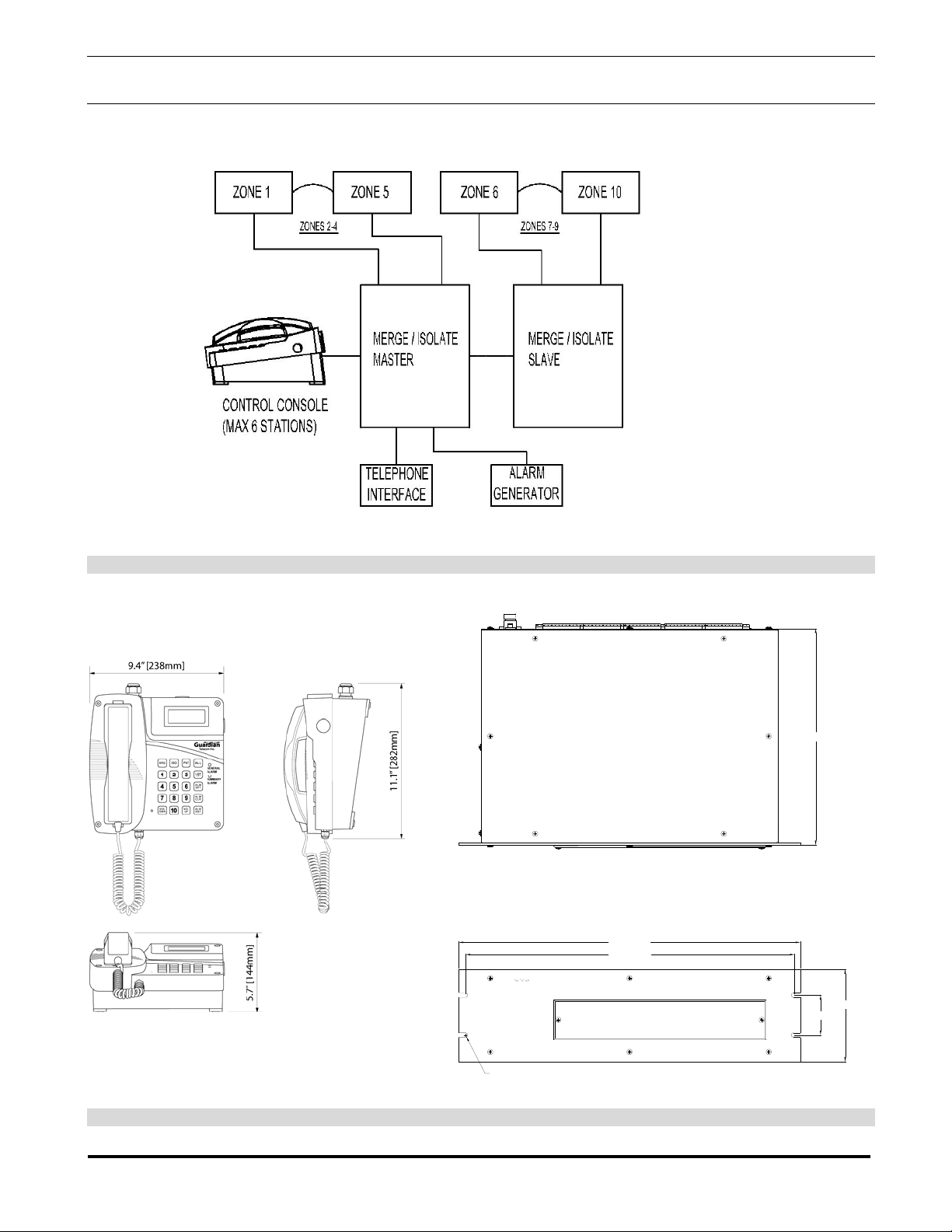
Figure 1 - System Block Diagram .........................................................6
Figure 2 - Dimensions MICON & MICAB ..............................................6
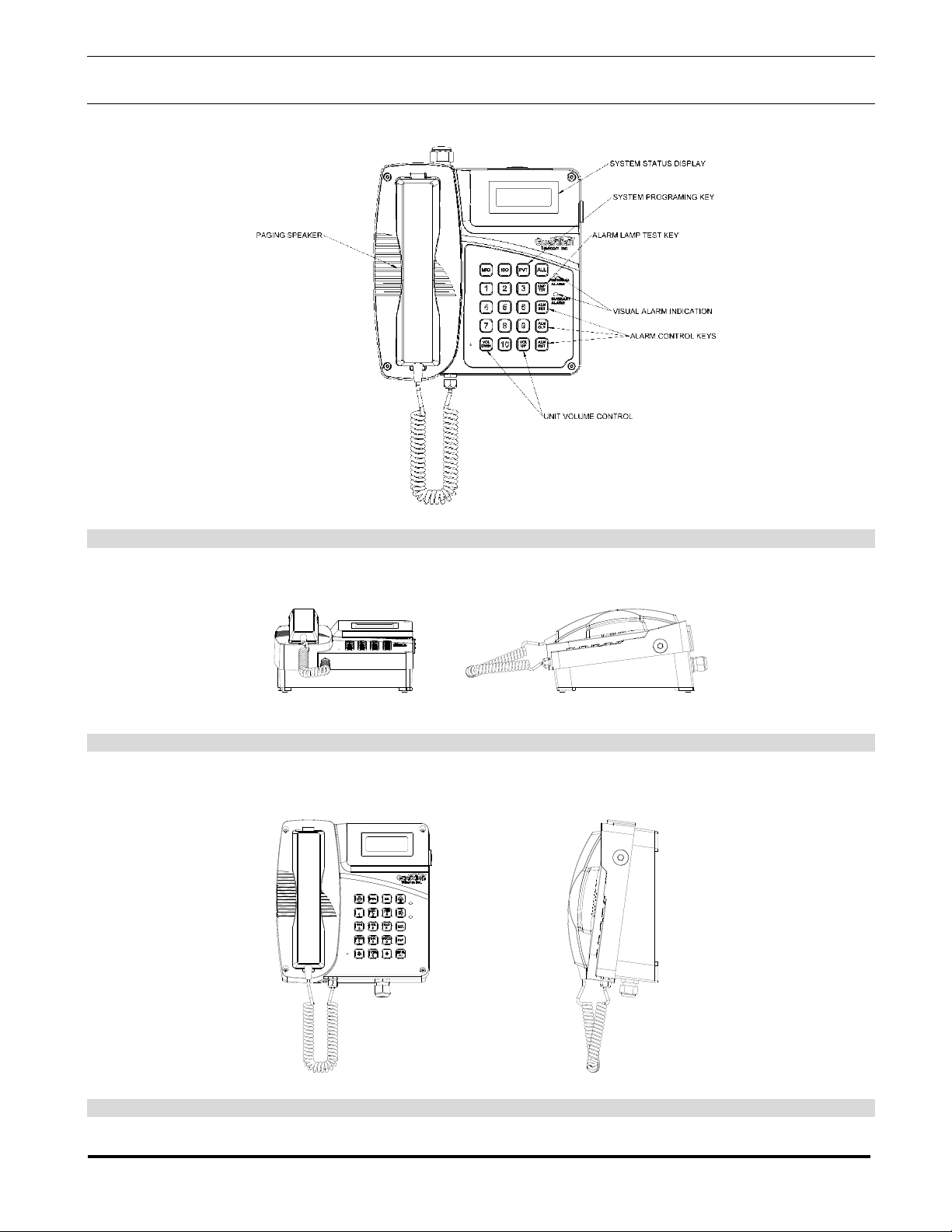
Figure 3 - MICON Features...................................................................7
Figure 4 - MICON Desk Top Mounting..................................................7
Figure 5 - MICON Wall Mounting..........................................................7
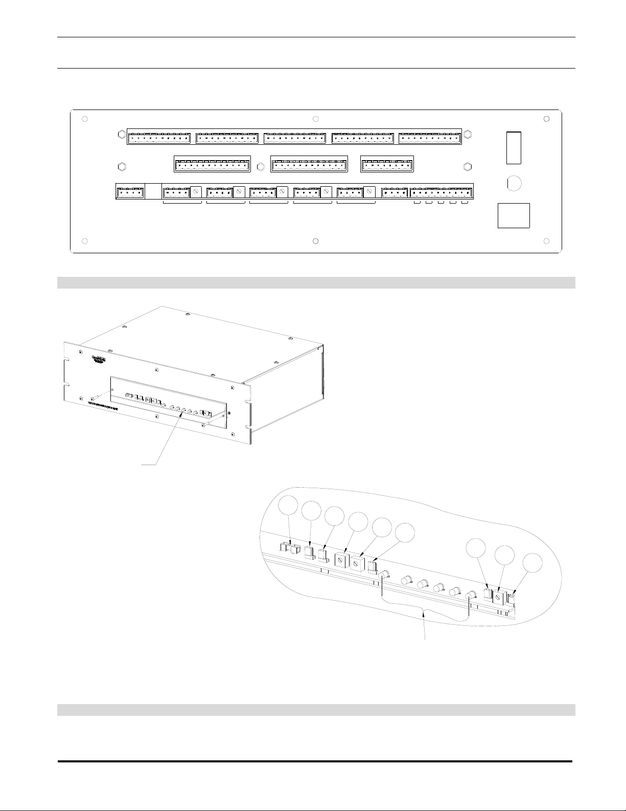
Figure 6 - Back Panel Wiring Connections ...........................................8
Figure 7 - Front Panel Adjustments ......................................................8
Figure 8 - MICON PCB Layout..............................................................9
Figure 9 - MICAB Jumper Settings .......................................................9
Figure 10 - Examples of Auxiliary Alarm Inputs ..................................11
Figure 11 - Page/Talk System Wiring (typical application)..................12
Figure 12 - Page/Talk Wiring Connections (Typical Application)........12
Package Contents
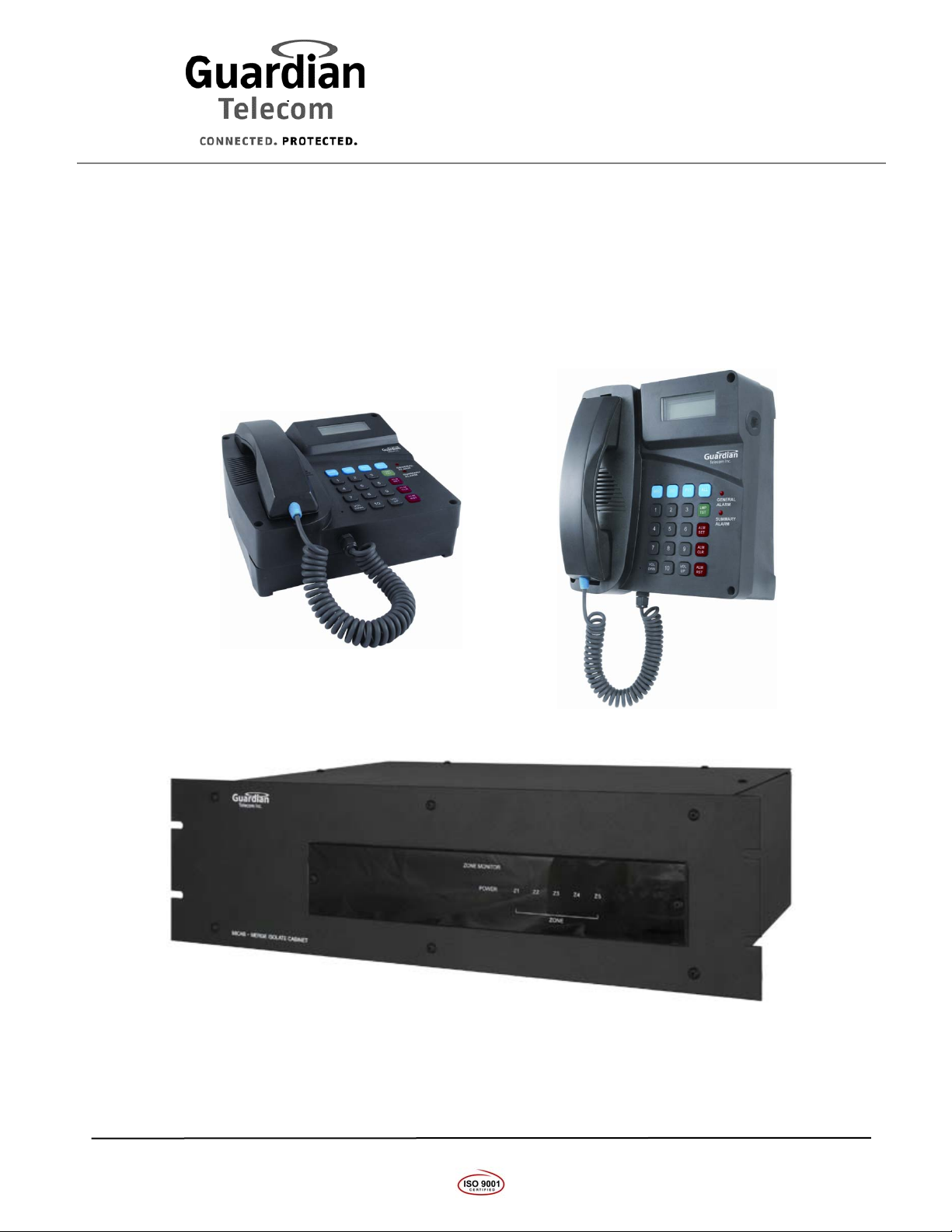
(1) P9000 Merge/Isolate Control System Master Switch Unit
(1 to 6) P9001 Merge/Isolate Control System Desk Sets
(1) Installation & Operation Manual
Page 2

Guardian Telecom Inc. Installation Programming Operation
Merge/Isolate Zone Control System
Overview
Merge/Isolate System
The function of the Merge /Isolate system is to merge and re-isolate up to five (or ten with
®
expansion unit) zones of Guardian Page/Talk or GAI-Tronics Page/Party
Amplifiers. The system is comprised of a Master Zone Control Unit (MICAB) and one to six
Control Console Stations (MICONs). Each MICAB has a five zone page line mixer, which
allows the master controller to simultaneously monitor merge requests through the page lines
of all zones. The system can merge 2, 3, 4 or all 5 zones and is also able to merge another
zone into a merged zone group later – for example zones 1 & 2 can be merged and zone 3 can
subsequently be added. The isolate function can be performed separately as well – for
example zone 2 can be re-isolated from zone 1 & 3 leaving them to converse alone. The
system has controls to merge and isolate all five zones in one step, which is very useful in
emergency situations. The system has the ability to be configured so that if an alarm occurs
and the operator needs to send a page, the alarm will be muted while the MICON is in paging
mode. When the Push To Page is released, the alarm tone returns to full volume.
system Stations and
The MICON has the ability to trigger and reset up to 10 alarm channels from an alarm
generator, such as Guardian’s AG17. It also displays two summary alarms in the form of LED
indicators. The inputs for these are located on the MICAB and are a simple dry contact format.
Some examples for use of the two alarms monitors are; the facility alarm activation, which
could show that an alarm has been activated somewhere in the facility, either from the MICON
or from an external switch. The other could be tied into a UPS or door switch or other sensor
as considered essential to provide a visual monitoring aid.
The MICAB has connections for a telephone interface which – with operator assistance –
allows telephone calls to be made and received.
The system has one set of Page & Talk merge bus lines – the common Page Line & one predetermined Talk Line. Separate merged zone groups is not achievable, only one group of
merged zones at one time can be performed.
The system can accommodate up to six MICONs working in parallel. It can also be expanded
with another Five Zone MICAB working in tandem for merging and isolating up to ten
Page/Talk zones. The MICAB can be configured by the factory for 120VAC, 230VAC or
24VDC operation.
The MICONS are phantom powered by the MICAB eliminating the need for a local power
supply for each MICON. The MICABs are rack mounted units with user access to zone
conductor terminations (one pair of page & one pair of talk wires per zone), Alarm Control, and
Telephone Interface terminations.
Each MICON can be programmed for a unique level of control which can range from a low
level monitor desk set with no control up to a full control unit. This offers the advantage of
limiting what alarms or zones a station can set, clear or merge.
Page 3

Guardian Telecom Inc. Installation Programming Operation
Merge/Isolate Zone Control System
MICON Features
Construction
Can be configured for Desktop or Wall mount
Magnetic reed hook-switch (> 1,000,000 operations)
Glass Filled Polyester Thermoset housing
Integrated paging speaker
Noise Canceling Microphone
Removable Handset Latches for on hook retention
Ergonomic handset with push to page button
Heavy-duty industrial handset cord
Heavy Duty Urethane Coated Water Tight Membrane Keypad
2 Line X 16 Character Back Lit LCD Display
Hearing aid compatible receiver
Extended length (up to 20ft) handset cord - Contact Guardian Sales for details
Cable Entrances
Includes 1 cable gland
Support for two additional glands for external peripherals
Mounting
Simple field installation - desktop or wall mount
Each MICON comes with 50M (164ft) of cable but will operate up to 500m
(1,640ft).
Options
Extended length handset cord 6m (20ft) - Contact Guardian Sales for details
Extended MICON cable – Contact Guardian Sales for details
Page 4

Guardian Telecom Inc. Installation Programming Operation
Merge/Isolate Zone Control System
MICAB Features
Construction
Heavy duty Steel – Corrosion protected and powder coated.
Standard 19” Rack Mount – 3U height
Connectors
Screw terminals accommodate up to 14 AWG cable
Indicators and Controls
Front Panel LED displays merged zones
Front and back panel access to system audio controls and configuration.
Support
Five Zones, can be expanded to ten zones
Up to 6 Master Control Stations
Alarm tone generator
Telephone interface module
Alarms
Remote Alarm Control and Monitor
System Summary Alarm
Support for Data Communications Monitoring
Support for door alarm, loop power monitoring (Optional)
Mounting
Rack mount
Options
Rack door alarm switches, and loop power monitoring sensors
Page 5
Guardian Telecom Inc. Installation Programming Operation
Merge/Isolate Zone Control System
Figure 1 - System Block Diagram
12.2" [310mm]
19.0" [483mm]
18.3" [465mm]
Guardian
Telecom Inc.
5.2" [132mm]
2.25" [57mm]
MICAB-MERGE ISOLATE CABINET
R0.125" [R3mm]
Figure 2 - Dimensions MICON & MICAB
Page 6
Guardian Telecom Inc. Installation Programming Operation
Merge/Isolate Zone Control System
Figure 3 - MICON Features
Figure 4 - MICON Desk Top Mounting
Figure 5 - MICON Wall Mounting
Page 7
Guardian Telecom Inc. Installation Programming Operation
Merge/Isolate Zone Control System
MICON 1 MICON 2 MICON 3 MICON 4 MICON 5
TALK
PAGE
PTTI ZONE 1
ALARM LOGIC INPUT ALARM LOGIC OUTPUT A ALARM LOGIC OUTPUT B
TALK
PAGE
TALK
LINE Z
ADJUST
PAGE
ZONE 2 ZONE 3 ZONE 4 ZONE 5
LINE Z
ADJUST
TALK
PAGE
LINE Z
ADJUST
TALK
PAGE
LINE Z
ADJUST
TALK
PAGE
LINE Z
ADJUST
+-+
12
AUX ALARM
INPUTS
-
TALK
DATA
PAGE
MASTER/SLAVE
PWR
MIX
POWER
FUSE 1.25A
120VAC
Figure 6 - Back Panel Wiring Connections
SEE DETAIL 1
R17 Data Threshold Pot
R154 Mixed Line Level Pot.
R60 Merged Page Line Level Pot.
Refer to Figure 9 for detailed jumper settings
Figure 7 - Front Panel Adjustments
F2
JP3
JP4
17
R
154
DETAIL 1
JP2
MERGED ZONE
INDICATOR LED
JP5
60
R
JP1
R
Page 8

Guardian Telecom Inc. Installation Programming Operation
Merge/Isolate Zone Control System
RX
VOLUME
SIDE TONE
CONTROL
TX
VOLUME
DATA
THRESHOLD
CONTROL
HANDSET
MIC + (BLACK)
MIC - (WHITE)
RX (YELLOW)
RX (YELLOW)
PTP (RED)
PTP (GREEN)
LCD DISPLAY
HOOK SWITCH
J7
J6
J5
Pin # Function
1 Merged Talk Line A
2 Merged Talk Line B
3 Merged Page Line A
1
J3
J4
J1
4 Merged Page Line B
5 Data Signal A
6 Data Signal B
7 24VDC
8 VDC Ground
10
9 Mixed Signal A
10 Mixed Signal B
Note: Cable has one spare pair of
conductors
MICON Connector
45
SPEAKER
J2
MICON CABLE
Figure 8 - MICON PCB Layout
JP1 – Merged Talk Line Impedance Control
Position Pins Description
1, 2 PTTI Not Installed
2, 3
PTTI Installed or Slave MICAB
Configuration
JP 2, 3, 4 – Master / Slave Control
Position
JP2 JP3 JP4
Pins Description
1, 2 Master MICAB Select
2, 3 Second MICAB Slave Select
JP5 – Merged Page Line Impedance Control
Position Pins Description
1, 2 Master MICAB Select
2, 3 Slave MICAB Select
Figure 9 - MICAB Jumper Settings
Page 9
Guardian Telecom Inc. Installation Programming Operation
Merge/Isolate Zone Control System
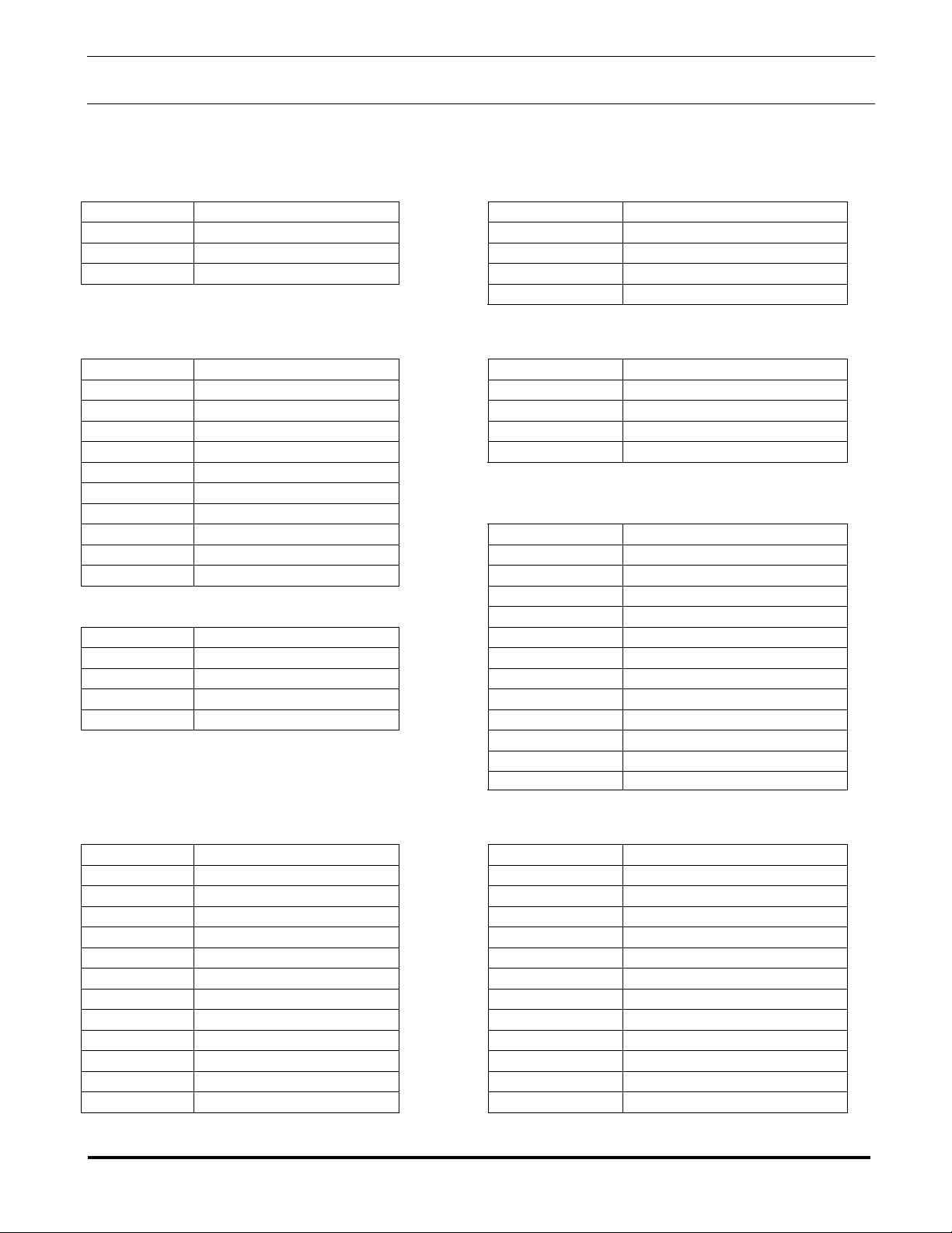
MICAB Back Panel Connector Tables
(pin numbering is from left to right)
Power Input Connector Aux. Alarm Input Connector
Pin # Function
1 Neutral 1 Warning 1 - Dry contact input
2 Ground 2 Ground
3 Hot 3 Warning 2 - Dry contact input
4 Ground
Master / Slave Connector
Pin # Function
1 Merged Talk Line A 1 Isolated Talk Line A
2 Merged Talk Line B 2 Isolated Talk Line B
3 Merged Page Line A 3 Isolate Page Line A
4 Merged Page Line B 4 Isolate Page Line A
5 Data Signal A
6 Data Signal B
7 N/C
8 VDC Ground
9 Mixed Signal A 1 Alarm I/P #1
10 Mixed Signal B 2 Alarm I/P #2
PTTI Connector
Pin # Function
1 Merged Talk Line A 6 Alarm I/P #6
2 Merged Talk Line B 7 Alarm I/P #7
3 Merged Page Line A 8 Alarm I/P #8
4 Merged Page Line B 9 Alarm I/P #9
10 Alarm I/P #10
11 Alarm I/P Common
Alarm Logic Output Connector A
(connected to AG17 Logic Inputs)
Pin # Function
1 Alarm O/P #1 1 Alarm O/P #9
2 Alarm O/P #2 2 Alarm O/P #10
3 Alarm O/P #3 3 Alarm RST 2
4 Alarm O/P #4 4 Alarm Mute
5 Alarm O/P #5 5 Alarm O/P Common
6 Alarm O/P #6 6 Alarm O/P Common
7 Alarm O/P #7 7 Alarm Tone Input+
8 Alarm O/P #8 8 Alarm Tone Input-
9 Alarm RST 1 9 Alarm RST 1
10 Alarm Mute 10 Alarm Mute
11 Alarm O/P Common 11 Alarm O/P Common
12 Alarm O/P Common 12 Alarm O/P Common
Pin # Function
Zone (1 - 5) Connectors
(Zone 6 -10 in Slave MICAB)
Pin # Function
Alarm Logic Input Connector
(connected to AG17 Logic Outputs)
Pin # Function
3 Alarm I/P #3
4 Alarm I/P #4
5 Alarm I/P #5
12 Alarm I/P Common
Alarm Logic Output Connector B
(connected to AG17 Logic Inputs)
Pin # Function
Page 10
 Loading...