

Page 1
4G, 8G Digital Direct Security
1 |
P a g e
Guardian Range
K-DVR-4G
K-DVR-8G
DVR
Instruction Manual
Page 2

4G, 8G Digital Direct Security
2 |
P a g e
CAUTION
TO REDUCE THE RISK OF ELECTRIC SHOCK, DO NOT REMOVE COVER.
NO USER SERVICEABLE PARTS INSIDE.
PLEASE REFER SERVICING TO QUALIFIED SERVICE PERSONNEL.
WARNING
TO PREVENT FIRE OR ELECTRIC SHOCK HAZARD, DO NOT EXPOSE THIS APPLIANCE
TO RAIN OR MOISTURE.
COMPLIANCE
This equipment has been tested and found to comply with the limits for a Class “A” digital device,
pursuant to Part 15 of the FCC Rules. These limits are designed to provide reasonable protection
against harmful interference when the equipment is operated in a commercial environment. This
equipment generates, uses and can radiate radio frequency energy and, if not installed and used
in accordance with the instruction manual, may cause harmful interference to radio
communications. Incorrect operation of this equipment in a residential area may cause harmful
interference in which case the users will be required to correct the interference at their own
expense.
FCC Caution: To assure continued compliance, use only shielded interface cables when
connecting to computer or peripheral devices. Any changes or modifications not expressly
approved by the party responsible for compliance could void the user’s authority to operate this
equipment.
This Class A digital apparatus meets all the requirements of the Canadian Interference Causing
Equipment Regulations.
These equipments comply with the European Council Directives:
Low Voltage Directive 2006/95/EC
EMC Directive 2004/108/EC.
Page 3

4G, 8G Digital Direct Security
3 |
P a g e
LIMITATION OF LIABILITY
● THIS PUBLICATION IS PROVIDED “AS IS” WITHOUT WARRANTY OF ANY KIND, EITHER
EXPRESS OR IMPLIED, INCLUDING BUT NOT LIMITED TO, THE IMPLIED WARRANTIES
OF MERCHANTABILITY, FITNESS FOR ANY PARTICULAR PURPOSE, OR NONINFRINGEMENT OF THE THIRD PARTY’S RIGHT.
● THIS PUBLICATION COULD INCLUDE TECHNICAL INACCURACIES OR TYPOGRAPHICAL
ERRORS. CHANGES ARE ADDED TO THE INFORMATION HEREIN, AT ANY TIME, FOR
THE IMPROVEMENTS OF THIS PUBLICATION AND/OR THE CORRESPONDING
PRODUCT(S).
DISCLAIMER OF WARRANTY
IN NO EVENT SHALL THE SUPPLIER BE LIABLE TO ANY PARTY OR ANY PERSON, EXCEPT
FOR REPLACEMENT OR REASONABLE MAINTENANCE OF THE PRODUCT, FOR THE CASES,
INCLUDING BUT NOT LIMITED TO THE FOLLOWINGS:
● ANY DAMAGE OR LOSS, INCLUDING BUT WITHOUT LIMITATION, DIRECT OR INDIRECT,
SPECIAL, CONSEQUENTIAL OR EXEMPLARY, ARISING OUT OF OR RELATING TO THE
PRODUCT;
● PERSONAL INJURY OR ANY DAMAGE CAUSED BY INAPPROPRIATE USE OR
NEGLIGENT OPERATION BY THE USER;
● UNAUTHORIZED DISASSEMBLE, REPAIR OR MODIFICATION OF THE PRODUCT BY THE
USER;
● ANY PROBLEM, CONSEQUENTIAL INCONVENIENCE, OR LOSS OR DAMAGE, ARISING
OUT OF THE SYSTEM COMBINED WITH THE DEVICES OF THE THIRD PARTY;
● ANY CLAIM OR ACTION FOR DAMAGES, BROUGHT BY ANY PERSON OR ORGANIZATION
BEING A PHOTOGENIC SUBJECT, DUE TO VIOLATION OF PRIVACY WITH THE RESULT
OF THAT SURVEILLANCE-CAMERA’S PICTURE, INCLUDING SAVED DATA, FOR SOME
REASON, BECOMES PUBLIC OR IS USED FOR THE PURPOSE OTHER THAN
SURVEILLANCE.
Page 4

4G, 8G Digital Direct Security
4 |
P a g e
PRECAUTIONS
●
Please refer all work related to the installation of this product to qualified service
personnel or system installers.
●
Do not operate the appliance beyond its specified temperature, humidity or power
source ratings.
●
Use the appliance at temperatures within 0oC ~ +45oC (32oF ~ 122oF) and humidity
below 85%.
●
The input power source for this appliance is +12 VDC. Use only the AC Mains to 12vDC
adapter as supplied with the DVR. Use of such other power adapter may cause damage
to the DVR not covered by the warranty.
●
Performance and lifetime of hard disk drives (HDD) are easily affected by heat (used at
high temperature). It is recommended to use this appliance at temperature within +20oC
~ +30oC (68oF ~ 86oF) to maximise HDD life.
●
It is possible to damage them if they are moved while their motors are still running. Do
not move the DVR just after turning the power on or off (for around 30 seconds).
●
Clean only with dry cloth.
●
Do not block any ventilation openings.
●
Do not use the appliance near any heat sources such as radiators, heat registers, stoves
or other apparatus that produce heat.
●
Protect the power cord from being stepped on or pinched particularly at plugs,
convenient receptacles and the points where they exit from the apparatus.
●
Do not drop metallic parts through slots. This could permanently damage the appliance.
Turn the power off immediately and contact qualified service personnel for service if this
occurs.
●
Handle the appliance with care. Do not strike or shake, as this may damage the
appliance.
●
Do not expose the appliance to water or moisture, nor try to operate it in wet areas. Do
take immediate action if the appliance becomes wet. Turn the power off and refer
servicing to qualified service personnel. Moisture may damage the appliance and also
cause electric shock.
●
Do not use strong or abrasive detergents when cleaning the appliance body.
●
Do not overload outlets/extension cords as it may result in a risk of fire or electric shock.
●
Please make a note of your settings and save them. This will help when you are
required to change the system configuration, or when unexpected failure or trouble
occurs.
●
Distributing, copying, disassembling, reverse compiling, reverse engineering, and
exporting in violation of export laws of the software provided with this product is
prohibited.
Page 5

4G, 8G Digital Direct Security
5 |
P a g e
Contents
Overviews
Overview & DVR features of the 4/8ch Guardian………………
Overview & DVR features of the 16ch Guardian………………
DVR and accessories
Remote Control……………………………………………………
Front and Back panel (Guardian 4ch without alarms)…………
Front and Back panel (Guardian 4ch) …………………………
Front and Back panel (Guardian 8ch) …………………………
Front and Back panel (Guardian 16ch) …………………………
GUI Operations
Main Screen…………………………………………………………
Logging In ………………………………………………………….
General Settings……………………………………………………
Record Settings……………………………………………………
Scheduling………………………………………………………….
Output……………………………………………………………….
Sequence……………………………………………………………
Alarm…………………………………………………………………
Motion………………………………………………………………..
External Sensor…………………………………………………….
Alarm Outputs………………………………………………………
COM Settings………………………………………………………
PTZ Settings………………………………………………………..
PTZ Control…………………………………………………………
Network Settings……………………………………………………
DDNS Settings……………………………………………………..
E-mail………………………………………………………………..
User Management/Account Settings……………………………
Playback……………………………………………………………
Backing up…………………………………………………………..
HDD………………………………………………………………….
Factory/Default Restore……………………………………………
System Info…………………………………………………………
Log Inquiry………………………………………………………….
Remote Access
Part 1 – LAN/Local Access……………………………………….
Part 2 – WAN/Outside Access……………………………………
Setting Up No-IP……………………………………………………
Netviewer……………………………………………………………
6
7
8
10
11
12
13
13
14
15
16
17
18
19
20
20
21
22
23
24
25
26
27
28
29
30
32
33
33
34
35
36
38
39
41
Page 6

4G, 8G Digital Direct Security
6 |
P a g e
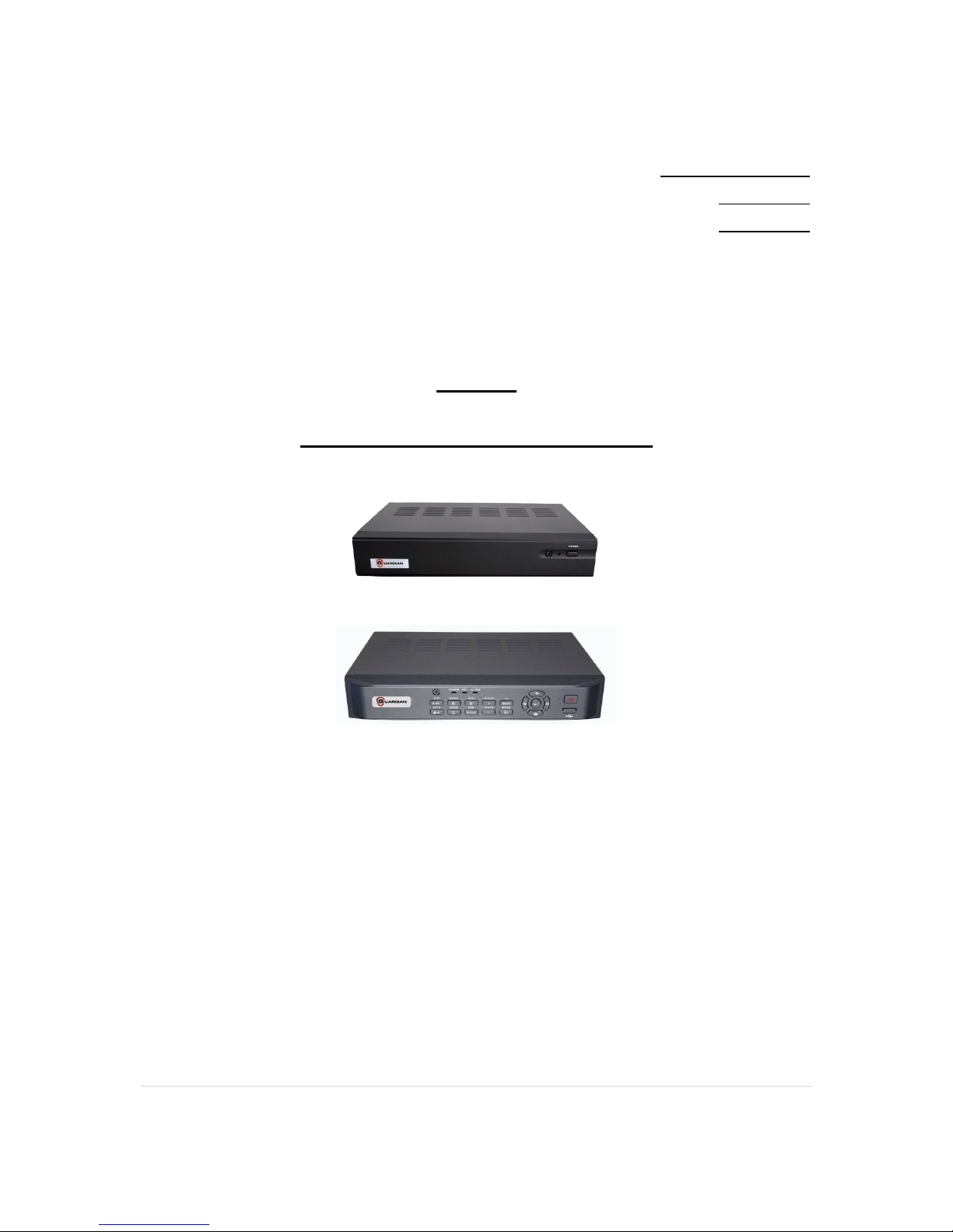
Overview & DVR features of the 4 Guardian Lite
The H.264 Guardian series digital video(&audio) recorders are designed for use within
an environment where surveillance, recording and monitoring are required. A DVR is
a combination of a Hard Disk Recorder, video multiplexer and web server. To achieve
the highest inter-connectivity and inter-operability this series of digital video/audio
recorders are based on industry-leading H264 compression standards.
DVR Features
Features (4 Channel Guardian Lite Models)
● Up to 4 cameras can be connected (BNC).
● H.264 baseline profile video compression/decompression
● Up to 2 audio inputs including PC microphone, G.711 audio
compression/decompression
● Real time operating system
● Supports up to 1 Hard disk drive (Up to 2TB)
● Record Capabilities -
1 channel Full D1: 25IPS
3 channels CIF: 75IPS
● Real time live display
● Playback search by time or logged event
● Optional display formats full screen, 4 way split or sequential.
● Versatile Digital Zoom
● Motion detection with programmable area and sensitivity
● Privacy mask
● Alarm Triggering with configurable conditions and reactions (on selected models)
● USB 2.0 Backup facility
● Support USB mouse
● Ethernet interface for remote access through web server or client software
*Dependent on model
Page 7

4G, 8G Digital Direct Security
7 |
P a g e
Overview & DVR features of the 4/8ch Guardian
The H.264 Guardian series digital video(&audio) recorders are designed for use within
an environment where surveillance, recording and monitoring are required. A DVR is
a combination of a Hard Disk Recorder, video multiplexer and web server. To achieve
the highest inter-connectivity and inter-operability this series of digital video/audio
recorders are based on industry-leading H264 compression standards.
DVR Features
Features (4/8 Channel Guardian Models)
● Up to 4/8 cameras can be connected (BNC).
● H.264 baseline profile video compression/decompression
● Up to 2 audio inputs including PC microphone, G.711 audio
compression/decompression
● Real time operating system
● Supports up to 1 Hard disk drive (Up to 2TB)
● Record Capabilities -
Full D1: 50IPS
CIF: 100IPS
● Real time live display
● Playback search by time or logged event
● Optional display formats full screen, 4/*9 way split or sequential.
● Versatile Digital Zoom
● Motion detection with programmable area and sensitivity
● Privacy mask
● Alarm Triggering with configurable conditions and reactions (on selected models)
● USB 2.0 Backup facility
● Support USB mouse
● IR Remote
● Ethernet interface for remote access through web server or client software
*Dependent on model
Page 8
4G, 8G Digital Direct Security
8 |
P a g e
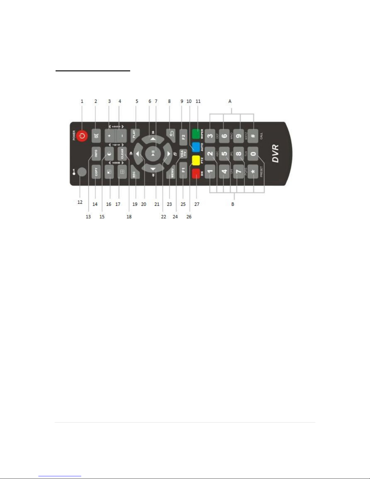
Remote Control
1. Power button - This button will start the shutdown procedure.
2. Mute button - This will mute the sound. (If in use.)
3. Focus + button - This will increase the focus. (When available.)
4. Focus - button - This will decrease the focus. (When available.)
5. Play button - This will play footage or take you to the playback menu.
6. Right Arrow button - This will select “right” and fast forward during playback.
7. Play/Pause button - This button will play/pause footage during playback and also can
be use as “Enter” in the menus.
8. Back button - This will let the user go back one stage in the menus.
9. F2 button - NO FUNCTION
10. Auto button -
11. Wiper button - This function can only be used with a PTZ camera that has a wiper.
12. Lock Button - This will lock the DVR so it requires logging in again.
13. Info button - This will take you to the “System Information” menu.
14. Copy button - This will take you to the “Backup” menu.
15. Contrast button - This will take you to the “Video settings” menu. (To change contrast,
brightness, etc.)
16. Camera Scroll button - Once full screen mode you will be able to scroll through each
camera.
17. Grid Screen button - This will allow you to change the grid screen from the full amount
(4, 8 and 16) to 4 way screen and to full 1 camera screen.
18. Clear button - This is the delete button.
Page 9

4G, 8G Digital Direct Security
9 |
P a g e
19. Rec button - This will activate manual record.
20. Up Arrow button - This button is use for navigating “Up” in the menus and also for
activating slow motion during playback.
21. Left Arrow button - This button is used for navigating “Left” in the menus and also for
rewinding during playback.
22. Down Arrow button - This button is for navigating “Down” in the menus and also for
skipping frame by frame during playback.
23. Menu button - This will access the menus.
24. VGA TV button - NO FUNCTION.
25. F1 button - NO FUNCTION.
26. PTZ button - This will bring up the PTZ controls. (Only functional with a PTZ camera
installed.)
27. DN button - NO FUNCTION.
A + B. These buttons are the numerical and alphabetical keys, they will be used whenever
the user is required to input numbers and/or letters. (Press the button multiple times to scroll
though the letters and number on that key.
Page 10
4G, 8G Digital Direct Security
10 |
P a g e
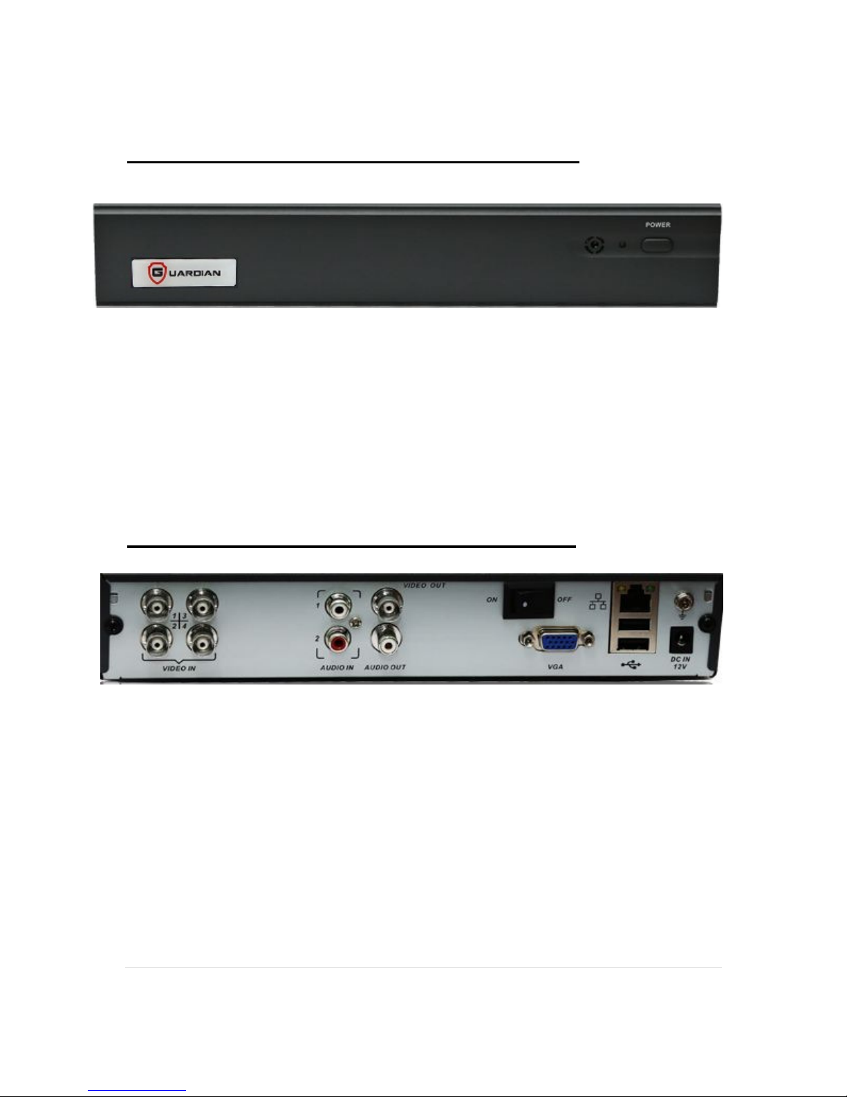
4 Channel Guardian: Front Panel Diagram
**Without alarm inputs**
1. Alarm Light - This light will flash when an alarm or motion is triggered.
2. Net Light - This light will flash when there is network activity.
3. REC Light - This light will flash when the DVR is recording.
4. Power Light - This light will be green when the unit is fully powered up and orange
when in standby mode.
5. Power/Standby Button - Once the switch on the back of the unit has been turned ON
the power light on the front will be orange, you will now have to press the power button
on the front to take the unit out of standby mode.
4 Channel Guardian: Back Panel Diagram
1. Video In - Video input connectors for cameras.
2. Audio In - Audio input connectors for devices such as microphones.
3. Video Out - Connection for a composite monitor/ TV.
4. Audio Out - Connection for speakers.
5. Mic In - Connection for a microphone.
6. VGA - Connection for a VGA monitor.
7. Ethernet - Connection for a network cable.
8. USB - Connection for a backup device or a mouse. (Mouse is suggested.)
9. DC IN - Connection for your AC Mains to DC 12V adapter to power the DVR.
10. ON/OFF - To switch the power on and off. (Only switch off AFTER shutdown procedure
has been completed.)
Page 11
4G, 8G Digital Direct Security
11 |
P a g e
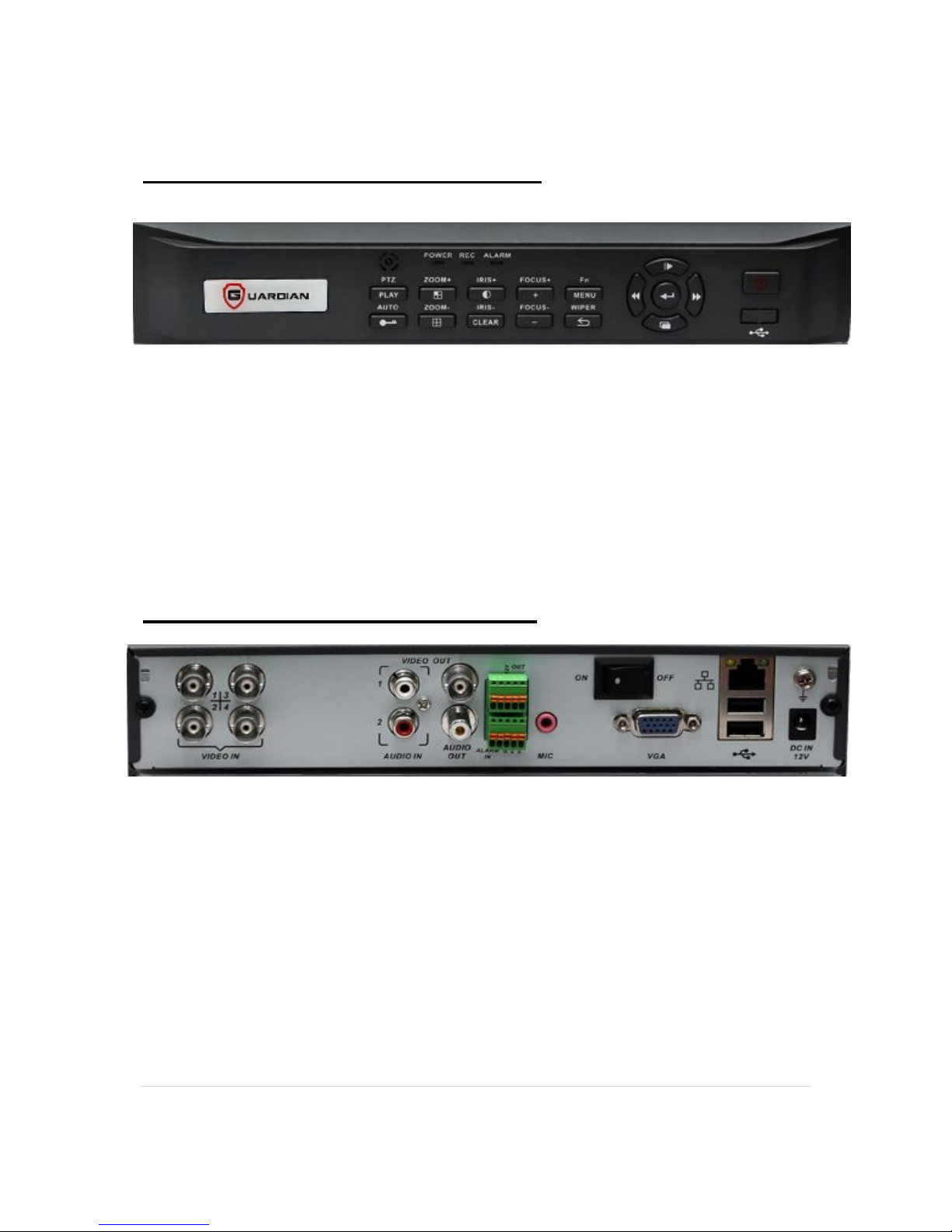
4 Channel Guardian: Front Panel
1. Alarm Light - This light will flash when an alarm or motion is triggered.
2. REC Light - This light will flash when the DVR is recording.
3. Power Light - This light will be green when the unit is fully powered up and orange
when in standby mode.
4. Power/Standby Button - Once the switch on the back of the unit has been turned ON
the power light on the front will be orange, you will now have to press the power button
on the front to take the unit out of standby mode.
Please refer to remote control guide for other button function(s).
4 Channel Guardian: Back Panel
1. Video In - Video input connectors for cameras.
2. Audio In - Audio input connectors for devices such as microphones.
3. Video Out - Connection for a composite monitor/ TV.
4. Audio Out - Connection for speakers.
5. Mic In - Connection for a microphone.
6. VGA - Connection for a VGA monitor.
7. Ethernet - Connection for a network cable.
8. USB - Connection for a backup device or a mouse. (Mouse is suggested.)
9. DC IN - Connection for your AC Mains to DC 12V adapter to power the DVR.
10. ON/OFF - To switch the power on and off. (Only switch off AFTER shutdown procedure
has been completed.)
11. Alarm In/Out - Connect these inputs to external devices such as PIR sensors or
door switches
.
Page 12
4G, 8G Digital Direct Security
12 |
P a g e
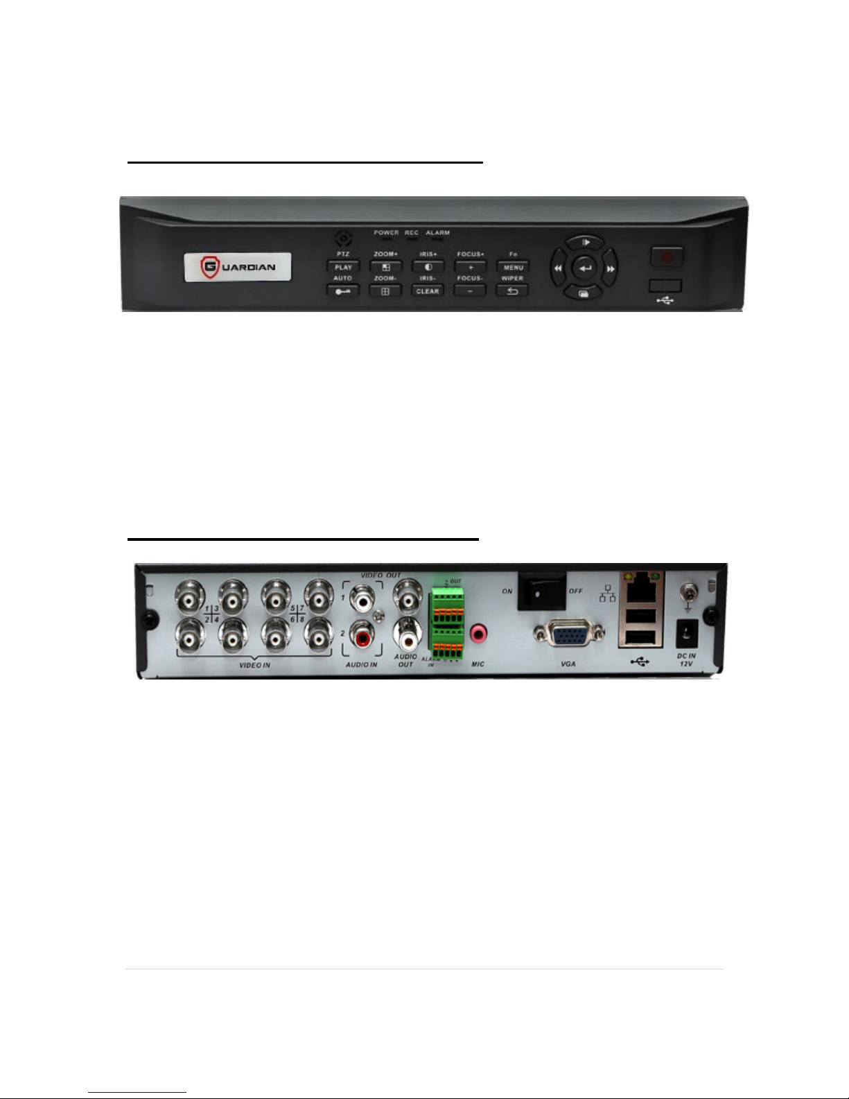
8 Channel Guardian: Front Panel
1. Alarm Light - This light will flash when an alarm or motion is triggered.
2. REC Light - This light will flash when the DVR is recording.
3. Power Light - This light will be green when the unit is fully powered up and orange
when in standby mode.
4. Power/Standby Button - Once the switch on the back of the unit has been turned ON
the power light on the front will be orange, you will now have to press the power button
on the front to take the unit out of standby mode.
Please refer to remote control guide for other button function(s).
8 Channel Guardian: Back Panel
1. Video In - Video input connectors for cameras.
2. Audio In - Audio input connectors for devices such as microphones.
3. Video Out - Connection for a composite monitor/ TV.
4. Audio Out - Connection for speakers.
5. Mic In - Connection for a microphone.
6. VGA - Connection for a VGA monitor.
7. Ethernet - Connection for a network cable.
8. USB - Connection for a backup device or a mouse. (Mouse is suggested.)
9. DC IN - Connection for your AC Mains to DC 12V adapter to power the DVR.
10. ON/OFF - To switch the power on and off. (Only switch off AFTER shutdown procedure
has been completed.)
11.
Alarm In/Out - Connect these inputs to external devices such as PIR sensors or
door switches
.
Page 13
4G, 8G Digital Direct Security
13 |
P a g e
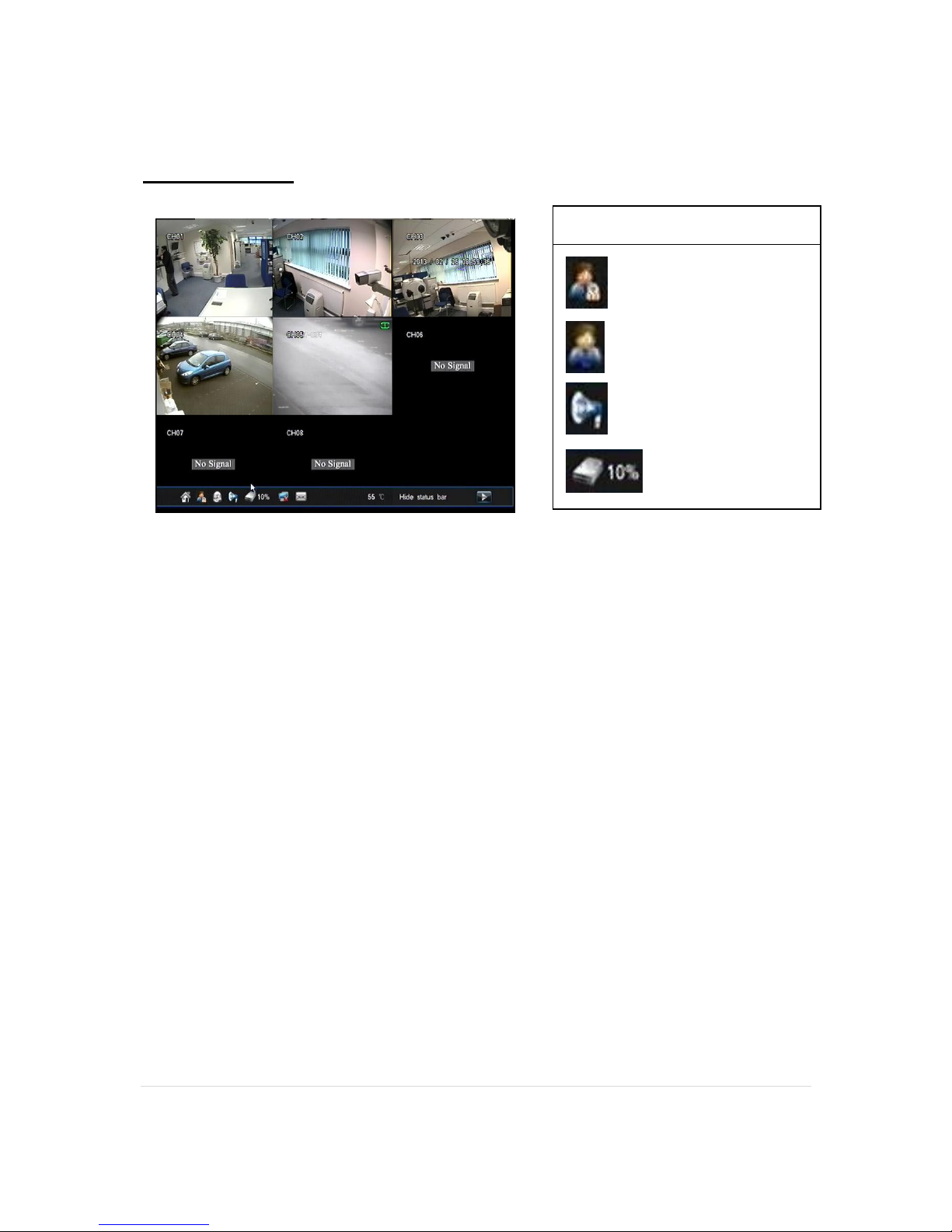
Main Screen
DVR is locked.
User is logged in.
Audio is ON
HDD percentage.
• If the DVR is “locked” then you can unlock it by right clicking on the mouse or pressing
the menu button on the remote/front panel.
• If the DVR is “unlocked” or logged in it means you can perform any operation that your
user level permits. See page 29 “User Management”
• If audio is on you can use the system in conjunction with microphones. Please note that
microphones are not recommended for external use/recording.
• The percentage sign at the bottom of the screen shows you how full your HDD is. Please
note that the HDD percentage sign becomes irrelevant once recycle record is activated.
The unit will record over the oldest data once the HDD is full. All DVRs leave DDS with
this feature activated.
Key Icons
Page 14
4G, 8G Digital Direct Security
14 |
P a g e
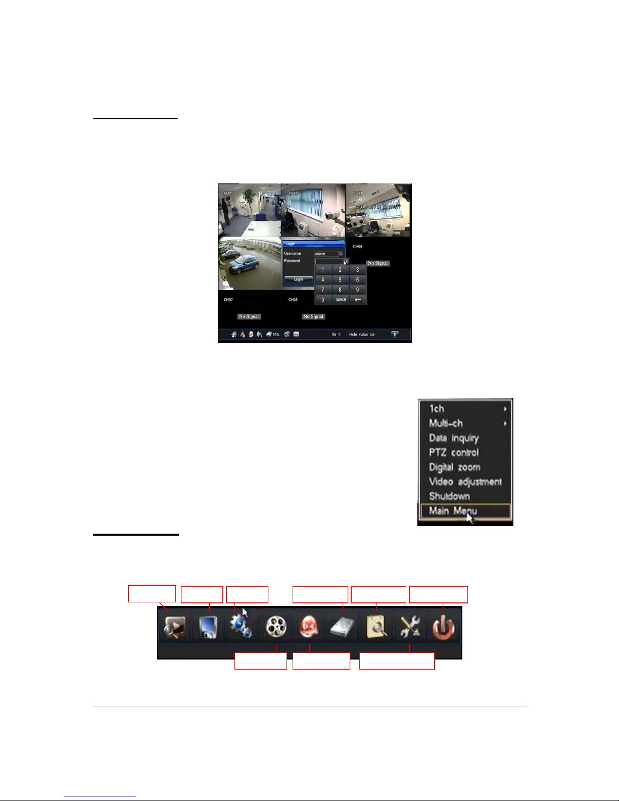
Logging In
Before you are able to use any of the DVR features you MUST log in. To start the log in
procedure you simply have to either RIGHT CLICK your mouse or PRESS MENU on your
remote and you will be presented with the screen shown below;
Once you have input your USERNAME and PASSWORD you will be able to RIGHT CLICK the
mouse or press the MENU BUTTON on your remote to access the menus. (shown below.)
●
Main Menu - Access the main menu.
●
Channel switch - Switch between number of channels.
●
Data inquiry - Access the playback function.
●
PTZ control - Displays the controls for a PTZ camera.
●
Video adjustment - Access settings for brightness, contrast,
etc.
●
Digital Zoom - Starts the zoom function.
●
Shutdown - Starts the shutdown procedure.
Main Menu
You can gain access to the Main Menu after you’ve logged in. You have a choice of the
following options.
**The default Username is "admin" and the default Password is "888888".**
Playback
Backup
Config.
Man. REC
Man. Alarm
Config
.
Page 15
4G, 8G Digital Direct Security
15 |
P a g e
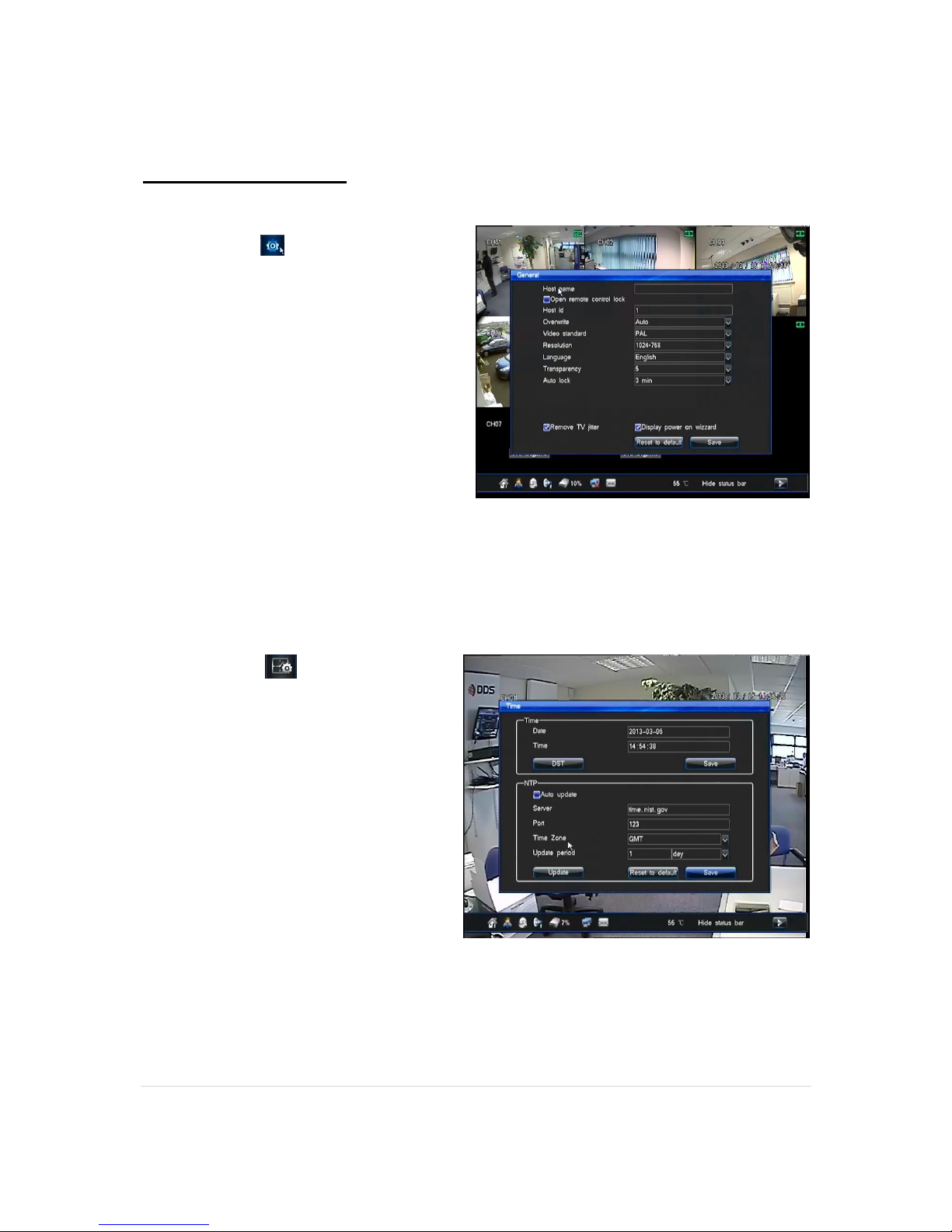
General Settings
The parameters that can be configured in the
“General” option (can be accessed from
the “Config” menu) are:
● Overwrite - Select if the HDD
overwrites when full.
● Language - Select Language.
● Video Format - PAL (UK/EUROPE)
or NTSC. (AMERICA(S))
● Resolution – Adjust video output
resolution.
● Transparency - This option allows
you to set whether you can see
cameras through the menu screen.
● Auto Lock - Time before the unit logs
out.
● Remove TV jitter - Tick this box to stabilise the image if jittery.
If you wish to restore these settings to Factory Default you can select the “Default” button or if
you wish to save any changes made you can select the “Save” button.
The Parameters that can be configured in
the “Time” option (can be accessed
from the “Config” menu) are:
● Date - Day / Month / Year
● Time - Hour : Minutes :Seconds
● Auto Update - Whether you want
your DVRs time to update
automatically with an NTP server.
● Server - Which time server you wish
your DVR to sync with. For GMT use
“time.nist.gov”.
● Port - What virtual port can the
server be reached on. For most
servers this can be left at default.
● Time Zone - Which time zone you
wish to sync with.
● Update Period - How often you wish to sync the time/date.
Page 16

4G, 8G Digital Direct Security
16 |
P a g e
Record Setup
Within the record menu (can be
accessed from the “Config” menu) you will
be able to adjust different record
parameters.
•
Channel No: Here you will be able to
choose which channel you wish to alter
the settings on.
•
Record Mode: This tab will allow you to
choose which mode the channel will
record in. The modes you can select are
"MANUAL, SCHEDULE, MOTION,
ALARM.". Each channel can be set
independently.
•
Definition: On the 4, 8 and 16 channel
Guardians you will be able to change the channels definition from D1 to CIF.
•
Bit Rate Type: CBR (Constant bit rate) keeps the set data rate to your setting over the
whole video clip. Use CBR only if your clip contains a similar motion level across the entire
duration.
VBR (Variable bit rate) adjusts the data rate down and to the upper limit you set, based on
the data required by the compressor. VBR takes longer to encode but produces the most
favourable results.
• Image Quality: 5 levels of quality to choose from are HIGHEST, HIGH, MIDDLE, LOW, and
LOWEST.
• Frame Rate: With this tab you will be able to select the rate at which the channel will record.
• Bit Rate: The term bit rate is a synonym for data transfer rate. Bps = Bytes per second, bps
= bits per second. The digital equivalent of bandwidth, bit rate is measured in bits per
second. It is used to express the rate at which the compressed bit stream is transmitted.
The higher the bit rate, the more information that can be carried.
• Pre-record: Here you can define how much footage in seconds (e.g. 20 seconds worth) will
be saved before any motion event starts.
• Post-record: Here you can define how much footage in seconds will be recorded after the
motion event has stopped.
Record Icons
Motion record : will display a YELLOW tape icon when recording.
Scheduled record : will display a BLUE tape icon when recording.
Manual record : will display a GREEN tape icon when recording.
Alarm record : will display a RED tape icon when recording.
Page 17

4G, 8G Digital Direct Security
17 |
P a g e
Scheduling
The Scheduling menu (can be accessed from the “Config” menu) will cover all aspects of
setting up a schedule. The two settings pages that are used for schedule creation are Record
Settings and Alarm Settings.
As an example this guide will show setting up a schedule for opened and closed periods of a
typical shop.
• First locate the Record Settings tab > then
select the Schedule tab. Within here you will
be setting when you wish the DVR to record
constantly.
• If you wish to have the same schedule for
every day tick ALL. However you are able
to create individual schedules for each day
by using the provided days.
• Once you have ticked ALL you will see the
entire row turn orange (orange means it will
record at these points.)
• Now you will be able to click and drag to
make a grey gap in the middle (or area of your choosing) of the orange bar. These grey
areas are where the DVR is NOT recording. (Note: Make note of the start time and end
time of the grey areas as this will be the start and end points for the motion
schedule.)
• Now that you have chosen the areas (in orange) where you wish the DVR to record
constantly you can now click SAVE. If you wish to apply this schedule to more than one
camera channel click COPY.
• Next you will need to set the motion schedule to cover the points in the day when the DVR
isn't recording constantly. You will need to locate the ALARM SETTINGS tab> MOTION tab.
• You will need to click and drag the orange bars from the start time and end time where the
DVR is not recording constantly, these orange areas are where the DVR is recording on
motion detection only.
• Click SAVE.
Page 18

4G, 8G Digital Direct Security
18 |
P a g e
Output
The Output menu (can be accessed from the
“Config” menu) is where you will be able to choose
how and what information will be displayed on
screen.
To enter the Display Settings tab you will need to
locate the OUTPUT SETTINGS tab.
Channel Settings
• Channel no. : The box will allow you to make
changes to individual cameras. Select each one using
the drop down box.
• Channel name : In this box you can name the
individual channels whatever you wish and it will
replace the default CH01, CH02, etc on the live view.
• Video adjustment : This button will take you to the settings where you can adjust the
brightness, contrast, etc for each channel.
• Channel name position : This button will allow you to re position where the channel name
will sit on the screen. By default it is the in top left hand corner.
OSD Settings (On screen display)
• Date Format : Drop down box gives you the option
of changing the date layout.
The next four tick boxes will allow you to turn off the
time, day of the week, the channel name and the
DVRs temperature from being visible on the status bar.
Page 19

4G, 8G Digital Direct Security
19 |
P a g e
Output Continued…
Sequence
The sequence tab will allow you to set your DVR's cameras to display in sequence. i.e. each
camera will take turns in displaying for a programmed amount of time at full screen or a set
number of channels (4 and 8 way division sequencing is only available on DVRs with more than
4 channels.)
Note: In order for the sequencing to be
activated the user must log out and the
DVR needs to be in "locked" status.
• Sequence cycle(s) : In this box you
will determine how many seconds the
cameras will stay full screen before
changing to the next one.
• Division mode : Set the number of
channels to be displayed per
sequence page to 1, 4, 8 channels. (4 and 8 channel division sequencing not available on
4GL or 4G.)
• Sequence channel no. : This drop down box will allow you to set how many channels are
involved in the sequencing.
• The final row of numbered drop down boxes will allow you to change the order in which the
sequence will display the channels.
Page 20

4G, 8G Digital Direct Security
20 |
P a g e
Alarm
The Alarm section (can be accessed from the “Config” menu) of the manual will cover
Motion Masking and Motion Sensitivity.
**If you wish to learn about using the motion schedule please refer to "Scheduling" on
page 17. **
Motion
• Channel no. : This drop down box will allow
you to set each channel individually.
• Sensitivity : This option will allow you to
adjust the sensitivity for each channel, 1
being the least sensitive and 5 being the
most. If the channel is set to a lower
sensitivity it will take bigger movements to
activate the DVR to record, whereas a
higher sensitivity will activate recording with
less motion.
Linkage setting
• Trigger Record – Links the corresponding
camera to trigger motion recording on any
selected camera.
• Alarm Output – Triggers the alarm output when
motion is triggered.
• Linkage E-mail – Triggers e-mail sending when
motion is triggered. Please see page 28 for e-
mail setup.
Page 21

4G, 8G Digital Direct Security
21 |
P a g e
Alarm Continued…
Motion Area
The Motion Area is a function you can use to "mask
out" certain areas of the cameras view so that the
DVR does not detect motion in these areas.
For example, if a tree was swaying a lot in the wind it
will trigger motion recording. If you were to mask out
the area of the tree it would not trigger motion.
• If you wish to mask out an area simply click and
drag to create GREY boxes over the area you no
longer wish to trigger motion.
• Yellow areas are motion areas. If it is completely grey it will not detect motion anywhere.
• Double click twice to cancel your changes.
Sensor
(excluding K-DVR-4G1 model)
This menu allows you to configure what input
sensors (that can be connected to the DVRs Alarm
inputs) trigger. Examples of input sensors:
Pressure pads, PIR sensors, IR beams, dry
contacts etc.
You can schedule when you want sensors to
activate recording on certain cameras and/or
activate external alarms. You can first select which
sensor input you wish to configure, you can give
the sensor a name, select which hours of which day(s) you wish the sensor to trigger and finally
the expected result from the sensor triggering (record, alarm output, PTZ preset point or Email).
Below is an example on how you could set up a sensor.
Page 22

4G, 8G Digital Direct Security
22 |
P a g e
Alarm outputs
You can schedule when you want your alarm outputs (connected to the DVR) to trigger. The
alarm outputs can be activated by different “events” such as;
• HDD Errors
• Video Loss
• Network Disconnect
• High temperature warning
• Motion detection
• Alarm Inputs (sensors) **Not available on
selected 4ch Guardians**
You can schedule when you want the alarm outputs to be active. You can first select whether
the sensor is normally on or normally off, the dwell time of the alarm (in seconds), how the DVR
displays to you that the alarm output is active (by audio, buzzer or full screen) and select which
hours of which day(s) you wish the alarm outputs to be active.
It is important that you schedule the alarm outputs if you wish to use them. If your alarm outputs
are not scheduled then any function that is configured to utilise them won’t be able to trigger.
Alarm linkage
Here you can configure other Alarm types to set off the alarm outputs.
Page 23

4G, 8G Digital Direct Security
23 |
P a g e
COM
(Guardian 4, 8 and 16 channel only)
Com (can be accessed from the “Config” menu) is where you can configure all of the presetup of a PTZ camera.
You can configure the following options:
• COM no. – Here you can select
which communications port you are
using. 1 is RS485 and 2 is RS232.
• Serial Device – Select here what
type of device you are connecting to.
You will probably most likely be
using the PTZ option.
• Baudrate – Here you can select the
corresponding Baudrate that your
PTZ camera is set to.
Usually if the protocol of the PTZ camera is set to either Pelco D or P then the Baudrate
is 2400, 4800 or 9600.
• Data bit – This is part of the PTZ protocol code, please consult your PTZs manual for
this information. (this option is usually set to 8).
• Stop bit – This is part of the PTZ protocol code, please consult your PTZs manual for
this information. (this option is usually set to 1).
• Parity bit – This is part of the PTZ protocol code, please consult your PTZs manual for
this information. (this option is usually set to N/A).
• Bit rate control – This is part of the PTZ protocol code, please consult your PTZs
manual for this information. (This option is usually set to N/A).
• Enable Remote control lock – Enables remote control lock when using the DVRs
remote to control your PTZ camera.
• Host control code – Use this option if you have a keyboard plugged into multiple DVRs.
This code identifies this DVR.
Page 24

4G, 8G Digital Direct Security
24 |
P a g e
PTZ (Settings)
(Guardian 4, 8 and 16 channel only)
PTZ is where you can configure your PTZ (Pan Tilt Zoom) options.
You can configure the following options:
• Channel no. – Here you can associate the camera channel with your PTZ. E.g. if your
PTZ was plugged into channel 3 you would choose the number 3.
• Protocol – What protocol is your PTZ camera(s) set to? There is wide selection, but the
most common protocols are PELCO D and PELCO P.
• Address code – This depicts the ID that the PTZ camera is set to. This can be set to a
numerical value. (0 to 255)
• Polling – Configure automated polling. You can set the interval time.
• Cruise interval(s) – These are the presets the PTZ cam will go to when polling.
Page 25

4G, 8G Digital Direct Security
25 |
P a g e
PTZ control
(Guardian 4, 8 and 16 channel only)
This section concerns PTZ (Pan Tilt Zoom) cameras.
Once you have configured your DVR to control your PTZ camera(s) you can
bring up the PTZ control interface by clicking on the desired camera (to make
the PTZ camera picture appear full screen), right click on the camera for the
menu and click on “PTZ control”.
Once the PTZ camera panel has appeared you should have full control over your PTZ camera.
You should be able to pan the camera in any direction you like by clicking on the directional
arrows on the panel. You can adjust the speed of which the PTZ
camera moves (adjusting the “Speed” option). Zoom, focus and
IRIS functions can also be adjusted with the + & - buttons. The
switch button will take you to a slightly different panel where you
can program and call presets. It is here that you can also
change the channel number of the camera. The cruise setting
option will send the PTZ on cruise of presets that have been
pre-defined.
**Tip: Avoid using the centre button (located in the middle of the directional keys) which
initialises pattern programming as this takes a very long time to setup and must be
completed once started **
Page 26

4G, 8G Digital Direct Security
26 |
P a g e
Network Settings
In Network settings (can be accessed from the “Config” menu) you can configure your
DVR so you can put it on a LAN (Local Area Network). Once your router has been configured
you will be able to access your camera system across the internet.
Network
Options within this menu
• DHCP – This option can be checked or
unchecked. When this option is enabled
the DVR will pick up all IP information
from your router or independent DHCP
server. If this option is disabled you can
edit all the criteria below.
The IP, Subnet Mask, Default Gateway,
Primary DNS and Backup DNS can only be
edited if the DHCP option is unchecked.
These boxes should be filled in by an IT
professional or with instruction from one.
Putting inconsistent or incorrect values in here could have a detrimental effect on your
network.
• IP – You can edit the IP address of the system in these four boxes.
• Subnet Mask – You can edit the Subnet mask in these four boxes.
• Default gateway – You can edit the Default Gateway in these four boxes.
• Primary DNS – You can edit the Primary DNS in these four boxes.
• Backup DNS – You can edit the Backup DNS in these four boxes.
• Command port – This port is used for data transmitting. Port range is between 8000-
9000. Default is 8101.
• HTTP port – The port is used for the web interface. Port range is between 80-65535.
Default is 81.
• Multicast – Can be used when utilising UDP stream.
Page 27

4G, 8G Digital Direct Security
27 |
P a g e
DDNS (Dynamic DNS) Settings
Dynamic DNS is a service that maps Internet domain names to IP addresses. This service will
need to be used if you are NOT on a static (public) IP address.
The service we use that is tried and tested is called No-IP. (www.no-ip.com).
**For instructions on how to set up a No-IP account and hostname please refer to
"Setting up a No-IP account." on page 37 + 38.**
**If possible we suggest applying the DDNS information to your router instead of the
DVR. If your router does not support this function this menu is where you will need to
enter the information.**
• Server : In this drop down box you will
find three options "orey.net" and
"dyndns.com" and "no-ip.com". You
need to select "no-ip.com".
• Username : Once your No-IP account
has been created you will need to
enter the username you chose in the
username box.
• Password : Once your No-IP account
has been created the password you
create for your account will be entered
here.
• Auto Login : This option will need to be "ticked".
• Domain : The domain name will be the hostname you created that will be linked with your
dynamic IP address. The domain hostname will be entered in this box.
• Click SAVE before exiting this menu.
Page 28

4G, 8G Digital Direct Security
28 |
P a g e
Email
In order to use the email function successfully we suggest you create an account on the free
webmail service gmx.com. (Other email services may vary in success rate.)
GMX.com will only be used as the email sender you may still use any email service to receive
emails from the DVR.
Server : This box needs to be filled in with your
sender emails mail server. For example, gmx
mail server is "smtp.gmx.com".
Mail username : This option needs to be filled in
with the sender emails username. (Sometimes
the entire email address is the username, this
differs between services.) For example: gmx
requires the whole email address as a username
so in here you would enter "email@gmx.com".
Mail Password : The email sender password is to be typed here.
Sender Email : This is the email address that will be sending the notifications from the DVR.
Receiver Email : This is the email address you wish to receive the notifications on.
Port Number : The port will also be defined by the mail server. For example, gmx mail server
uses port 465.
Cycle (minute): This option will set the minimum amount of time (minutes) after each motion
event before another email can be sent. This option is used to stop excessive amount of emails
being sent if motion events are short.
Upload Snapshot : Ticking this option a snapshot of the initial trigger will be sent in the email
along with the channel number and time and date.
SSL Encrypt : This usually needs to be TICKED.
StartTLS : This usually needs to be UNTICKED.
Email Test : Pressing this button will send a test email which will allow you to check all the
settings are correct.
Once you have completed these settings you will need to go into either MOTION, ALARM or
SENSOR tabs (depend on which you use) and activate EMAIL LINKAGE.
Page 29

4G, 8G Digital Direct Security
29 |
P a g e
User Management/Account Settings
The account creation option will be found in "Sys. Settings" and in here you will be able to
create personal login usernames and passwords whilst also defining what privileges and
functions are available for specific user accounts.
• Add : The Add button will take you to the
privileges selection screen. (see 2nd image
below)
• Delete : If you wish to delete one of the
user accounts, highlight the name and click
delete.
• Edit : If you wish to edit any of the
privileges of a certain user, highlight the
name and click "edit" to be taken to the
privileges screen.
The "privileges" screen will be where you define
what each user has access to from being only
allowed to view playback for certain cameras to
being able to shutdown the unit.
Simply tick which cameras and menu areas you
wish to allow the user access to then click save.
Page 30

4G, 8G Digital Direct Security
30 |
P a g e
Playback
Click on “Playback” within the Main menu to bring up the playback screen.
The first screen you are presented with is “Time Inquiry”, from here you will be able to do a
precise time and date search to find a piece of footage. (providing it has been recorded.)
● Date – Here you can select a specific date
to play back from.
● Time – You can select a time by dragging
the bar across the table at the botton
● Camera Selection – You can select which
camera(s) you wish to playback or “All” of
them.
● Inquiry - This button will then produce you
a list of footage files from the specified date
and channel.
Once you selected a time, date and camera press play to view the footage.
● Camera Selection – You can select which
camera(s) you wish to playback or “All” of
them.
● Mode - This drop down box will allow you to
choose which type of record mode you wish
to search. (Motion, alarm, etc.)
● Date – Here you can select a specific date to
play back from.
● Inquiry - This button will then produce you a
list of footage files from the specified date
and channel.
To play a file select the desired file and then press play.
Once you selected a time, date and camera press play to view the footage.
Page 31

4G, 8G Digital Direct Security
31 |
P a g e
Playback Continued…
Once in playback a control bar will appear. The control bar at the bottom of the screen will
display various video controls.
Playback screen
Slider bar: By clicking and dragging this you can seamlessly scroll through different time
frames of the footage you are playing back.
This is the info box and
will display what option
you are hovering over.
Slow forward plays
the footage back in
slow motion
Rewind the footage at 2, 4, 8
and 16 speed. Click on the
icon to increase the speed.
Pause
the
footage
Fast forward the footage at 2,
4, 8 and 16 speed. Click on the
icon to increase the speed.
Frame forward
plays the footage
back frame by
frame.
Exit
playback
menu
Displays the
channel
(camera) you
are playing back
Displays
whether you are
playing back or
fast forwarding
etc. and at what
speed.
Displays the
time and date
stamp of the
footage you are
playing back.
The control bar
Page 32

4G, 8G Digital Direct Security
32 |
P a g e
Backing Up (Backup)
First insert your USB storage device in the one of the USB slots provided, this will cause the
DVR to automatically connect your backup device. Once connected you will see a prompt as
shown below.
This icon will appear at the bottom of the screen
Now you need to enter Backup from the main menu.
1. You must now select the CHANNEL NUMBER you wish to back up from.
2. Now double click on the DATE to bring up a calendar and choose which day you would
like to backup footage from.
3. Input the relevant START TIME and END TIME of the segment of footage you wish to
backup.
4. Now click ADD to add the file to the ITEMS list. (You are able to add 25 files to the item
list for backing up.)
5. Once you have added all the files to the list click BACKUP
After you have started the backup process you will see "Backup in progress...." and a
percentage informing you of what stage the backup is at. Once the backup is finished you will
see a prompt confirming its completion.
Page 33

4G, 8G Digital Direct Security
33 |
P a g e
HDD (Hard disk drive)
In the HDD menu (located in main menu) you will be able to check the status of your hard
drive and how much space has been used.
You will also be able to see the status of a USB stick if you have one plugged in via one of the
USB ports.
If you wish to format the HDD (**WARNING: THIS WILL ERASE ALL FOOTAGE FROM THE
HARD DRIVE.**) simply tick the relevant box next to the HDD you wish to format then click the
"Format" button at the bottom of the screen.
A percentage bar will show you the progress of the format.
Default Restore
The default menu (located in the “other settings” menu) is where you are able to
reset all the settings to factory default. You can also select individual sections to reset using the
tick boxes.
We advise giving our support team a call if you ever reset the DVR to default as some aspects
are pre configured before shipping and may need to be re configured.
Page 34

4G, 8G Digital Direct Security
34 |
P a g e
System Info
The Sys. Info. menu and the other info options are primarily used for checking the status of
the various functions.
System Info
This option will provide useful information such as the
current user level, IP address and firmware versions.
You will also use this screen to update your DVRs
firmware via USB if you are provided with one from DDS.
Record Status
This option will show you the current settings for
each channel. It will indicate what record type,
quality, definition the DVR is set to and it will also
indicate with audio is set on each channel.
Alarm Status
This option will show you when events such as sensors, motion detection and video loss are
triggered, the triggers are indicated by coloured lights
Sensor = Red
Motion = Yellow
Video loss = Blue.
This tab will also display when there is an HDD error
and if the network cable becomes disconnected.
Page 35

4G, 8G Digital Direct Security
35 |
P a g e
Log Inquiry
The log inquiry will serve as a place where you can check the entire goings on with your
DVR. It will provide information such as when certain functions are used like PTZ to if the unit is
ever shutdown abnormally.
• Main type : In this drop down box you will be able to select from;
o Operate : This option covers functions activated by the user, such as Playback and
shutting down the unit.
o Alarm ; This option will cover when functions such as motion and sensors have
been triggered.
o Abnormal : This option will cover errors such as video loss and HDD failures.
• Sub type : In this drop down box you will be able to specify further on the option you choose
in the Main type box
• Date : This box will let you choose which date you wish to search.
• Inquiry : Once you have selected the Main type, Sub type and Date you can now click the
Inquiry button and providing there is data to be found a list will be populated in the Inquiry
result box.
Page 36

4G, 8G Digital Direct Security
36 |
P a g e
Remote Access Part I
LAN access/ Local access
To gain remote access to your DVR on your computer you will first have to plug your DVR into
your router using an Ethernet network cable.
1. Now you must go into the Main Menu on the DVR and select the Network Settings
menu.
2. Now in the Network Settings menu you will find a DHCP tick box in the top left hand
corner, make sure this is ticked then press Save.
3. You should now see the default IP address has changed.
4. Take note of the IP address and type it into an Internet browser address bar at the
top of the screen (make sure you add :81 to the end) on a computer that is
connected to the same router as the DVR.
5. You will be presented with the screen below. You will be prompted to download
WebControl.exe before you can go any further. After installation you will need to restart
your browser.
***Please note above snapshot is taken from Google Chrome and screen may look
slightly different in other browsers.***
Page 37

4G, 8G Digital Direct Security
37 |
P a g e
6. Now that the WebControl.exe has been install and you have restarted your browser
you will see the login screen as shown below.
7. Next simply log in using the same login details as you would on the DVR itself.
***For details on how to use the Netviewer please refer to the Netviewer section of
this manual.***
***Note: This method will only give you local Internet access to your DVR.***
Page 38

4G, 8G Digital Direct Security
38 |
P a g e
Remote Access Part II
WAN access/ Anywhere access
Remote access part two will guide you through setting up your router so you are able to
connect to your DVR from anywhere in the world were a reasonable broadband service
operates.
First thing you need to do is follow the steps from part one (If you haven’t done so already) so
you are able to connect to your DVR locally
1. Now you are able to connect locally you will next need access to your router. You can
access your router by typing its address into an Internet browser address bar. (The
address will be your networks default gateway and may be written somewhere on the
actual router )
2. Now you have accessed your router the first thing you may wish to do is reserve the
DVRs IP address to the routers IP reservation table* (Please consult with your router
vendor or manual if you are unsure on how to do this)
3. You will now need to find a section on your routers configuration page called either
“virtual server”, “port forwarding”, “game and application sharing” or “firewall
rules”. In here you need to make a TCP rule for ports 8101 and 81.
4. Once you have made a rule that forwards these ports you need to assign them both to
your DVRs internal IP address.
5. If you have a static IP you will now be able to access your DVR from anywhere using
the static IP. If however you have a floating dynamic address you will need to read the
section within this manual called “Setting up a No-IP account.”. This will guide you on
how to setup a dynamic DNS account so that you can access your unit using a No-IP
hostname/website.
* Router may not have this function
***Due to the wide range of routers available we unfortunately can’t produce specific
guides to each one within this manual, however please contact us if you need a guide for
your router and we will do our best to source one.***
***We understand this configuration setup can be quite difficult so please do not hesitate
in calling us for assistance. One of our support engineers can configure your router
remotely for you.***
Page 39

4G, 8G Digital Direct Security
39 |
P a g e
Setting up a No-IP account
To set up your No-IP account you will need to be using the same Internet connection you
used for the initial DVR network setup. (Same router)
1. First thing you will need to do is go to www.no-ip.com. Once the page has loaded click
on "Create Account". You will then be presented with the "Create your No-IP account"
page.
2. Fill in the relevant details and make sure you use an email address you can access
straight away for verification purposes. Once you have clicked "I Accept, Create my
Account" a verification email will be sent to the specified email address.
3. Open the email from "unmonitored-webmaster@no-ip.com" and click the "activate
your account" link (3rd link down). You will need to sign in to complete the verification
process.
4. Now you have signed in you will need to locate and click "Host/Redirects". Once on the
"Manage Hosts" page you will next need to click "Add a Host".
5. You should now see the "Hostname Information" form. In this section you will be able to
create a hostname which will act as a website address which you will use to access
your DVR.
6. In the "Hostname" box, type something that is relevant to you (this will make up the first
part of your web address) and make sure the drop down box next to it is set to "no-
ip.org"
7. Now you have completed the hostname creation page click "Create Host"
8. You should now see your new hostname listed on the "Manage Hosts" page.
Page 40

4G, 8G Digital Direct Security
40 |
P a g e
9. You will now need to access your router and locate the section called "Dynamic DNS" or
"DDNS".
10. You will need to input the hostname, your no-ip.com email and your no-ip.com
password. You must also make sure the service provider is set to www.no-ip.com.
(Note all routers will vary consult your routers manual if you are unsure.)
***In rare cases where a router does not support no-ip.com you will be able enter your
information into the actual DVR***
Page 41

4G, 8G Digital Direct Security
41 |
P a g e
Net Viewer Functions
First thing you need to do once you have logged in is RIGHT CLICK on any channel and then
press OPEN ALL, this will start the video stream for each of your cameras.
Preview tab will let you view your cameras.
Playback tab will display the Playback screen.
Download tab will let you Backup footage to your computer.
Device Log tab will give you a detailed log of DVR operations.
Config tab will take you to the settings menu.
Page 42

4G, 8G Digital Direct Security
42 |
P a g e
Playback (Netviewer)
This activity timeline will display where footage has been recorded. Depending on the type of
record mode (Manual, Schedule, Motion, Alarm) certain colours will indicate the exact time a
recording has occurred.
By default it will always display the current days footage. If you wish to view another date you
will find a calendar (see image below) on the right and side of the screen.
Once you have clicked which date you wish to search you
next need to press the Inquiry button.
When you want to play a piece of footage simply double
click the coloured part of the timeline you wish to view.
The Local Play button will let you play footage already saved on your PC.
Page 43

4G, 8G Digital Direct Security
43 |
P a g e
Download/Backup (Netviewer)
This menu will allow you to backup footage straight to your computer.
When searching for footage you will use the inquiry box. In here
you will define which channel you wish to search and the start
time/date and end time/date.
Once all the information has been entered you will need to press
Inquiry. This button will return a list of video events that have
occurred between the two points you previously defined.
Once the list has been populated you will be able to select which
files you wish to backup by ticking the tick boxes on the left.
If satisfied with your selections next you will need to select where
on your PC you wish to save these files. You
can select a destination by using the button.
The final step once the files and save destination
have been selected is to press the button. You
files will now begin to download.
Page 44

4G, 8G Digital Direct Security
44 |
P a g e
Device Log
The device log with provide you with information regarding the DVRs operations.
You are able to define the start date and end date which will allow you to narrow the number of
log pages returned. You can do this by using the Inquiry box.
If you wish to save the log information you can do so by using the Log Path option.
To save you will need to select a folder you wish to save it to using the browse button. Once
chosen click Save Log.
Page 45

4G, 8G Digital Direct Security
45 |
P a g e
Config
The Config section will let you configure every setting of the DVR.
Please refer to the main manual for a description of each setting and what it changes.
PTZ Control
Whilst on the Preview Tab you will have access to the PTZ control
panel. From here you will be able to pan, tilt and zoom your PTZ
camera as well as access the presets.
**Note : Your camera must have PTZ capabilities in order to use
this**
Page 46

4G, 8G Digital Direct Security
46 |
P a g e
Para (Parameters)
Whilst on the Preview Tab you can access the Para tab
which will allow you to individually alter the brightness,
contrast, saturation and hue of each channel.
This can be used to improve the picture which may also
improve motion detection.
If you wish to return the settings to their original state press
the default button.
Channel Options
Whilst on the Preview Tab you are able to bring up channel
options by right clicking will allow you too.
• Switch between the main stream and the sub stream
• Take a snapshot.
• Force manual record
• Open audio channels (requires a mic)
• Close individual channels.
Page 47

4G, 8G Digital Direct Security
47 |
P a g e
Interface Map
 Loading...