

Guardian G3900LF Series, G3950LF, G3900LF Installation, Operation And Maintenance Manual
Note: This is a control system which must be cleaned and maintained regularly (see Maintenance Guide and Record card included with valve shipment).
1
Guardian Equipment
1140 N North Branch St
Chicago, IL 60642
312 447 8100 telephone
312 447 8101 facsimile
gesafety.com
rev. 1215 / © 2015 Guardian Equipment
Installation, Operation and Maintenance Guide
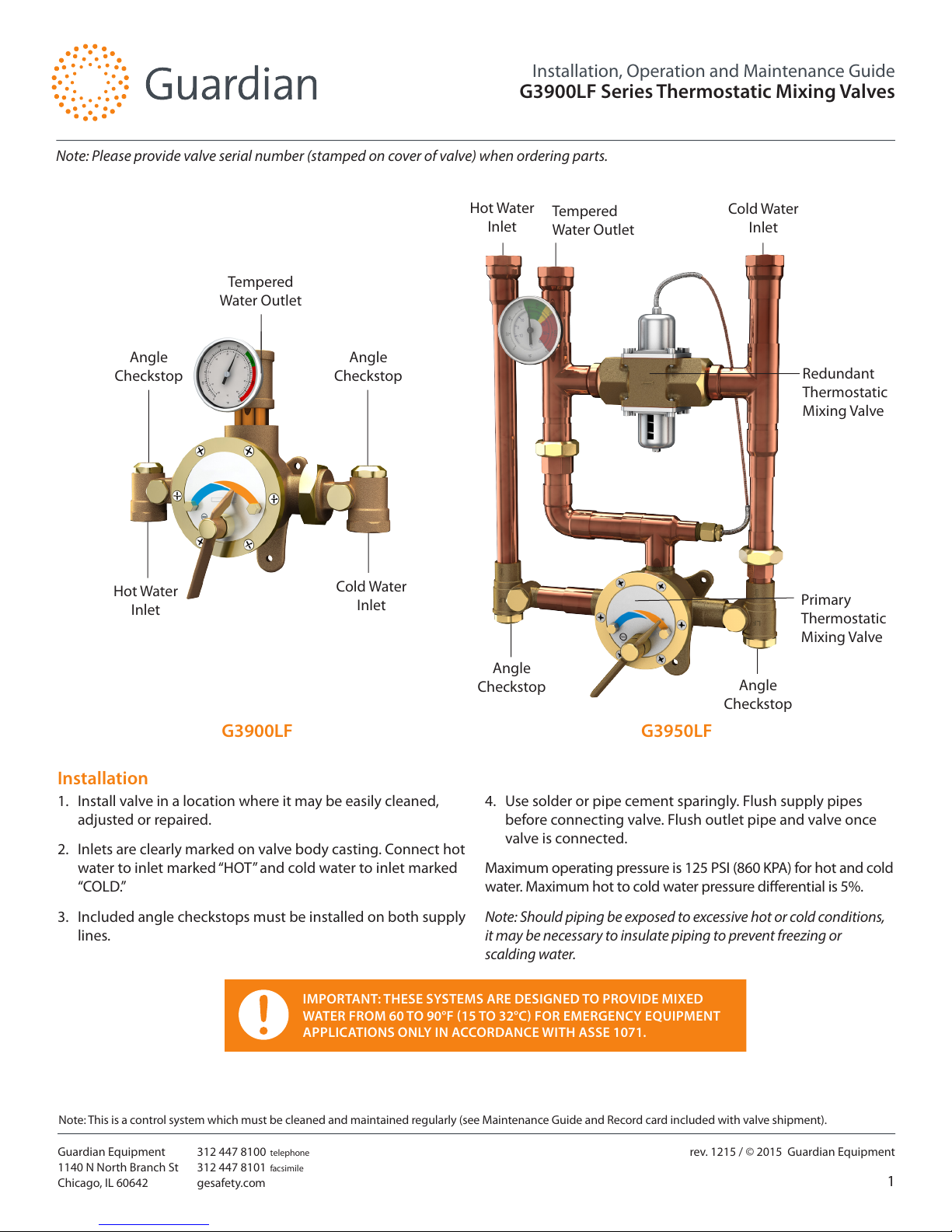
G3900LF Series Thermostatic Mixing Valves
Angle
Checkstop
Angle
Checkstop
Angle
Checkstop
Angle
Checkstop
IMPORTANT: THESE SYSTEMS ARE DESIGNED TO PROVIDE MIXED
WATER FROM 60 TO 90°F (15 TO 32°C) FOR EMERGENCY EQUIPMENT
APPLICATIONS ONLY IN ACCORDANCE WITH ASSE 1071.
Hot Water
Inlet
G3900LF
Installation
1. Install valve in a location where it may be easily cleaned,
adjusted or repaired.
2. Inlets are clearly marked on valve body casting. Connect hot
water to inlet marked “HOT” and cold water to inlet marked
“COLD.”
3. Included angle checkstops must be installed on both supply
lines.
4. Use solder or pipe cement sparingly. Flush supply pipes
before connecting valve. Flush outlet pipe and valve once
valve is connected.
Maximum operating pressure is 125 PSI (860 KPA) for hot and cold
water. Maximum hot to cold water pressure dierential is 5%.
Note: Should piping be exposed to excessive hot or cold conditions,
it may be necessary to insulate piping to prevent freezing or
scalding water.
Cold Water
Inlet
Tempered
Water Outlet
Cold Water
Inlet
Hot Water
Inlet
Tempered
Water Outlet
G3950LF
Note: Please provide valve serial number (stamped on cover of valve) when ordering parts.
Redundant
Thermostatic
Mixing Valve
Primary
Thermostatic
Mixing Valve
Note: This is a control system which must be cleaned and maintained regularly (see Maintenance Guide and Record card included with valve shipment).
2
Guardian Equipment
1140 N North Branch St
Chicago, IL 60642
312 447 8100 telephone
312 447 8101 facsimile
gesafety.com
rev. 1215 / © 2015 Guardian Equipment
Installation, Operation and Maintenance Guide
G3900LF Series Thermostatic Mixing Valves
Adjustment and Service
Guardian thermostatic mixing valves may be easily cleaned,
adjusted and repaired. Servicing may be possible without
disconnecting valve.
Note: Thermostatic water mixing valves are regulating mechanisms
which must be regularly maintained to provide best performance.
Local water quality and usage conditions dictate cleaning frequency.
(See Maintenance Guide and Record card included with valve
shipment and reference ANSI Z358.1)
WARNING: THIS THERMOSTATIC MIXING VALVE HAS
AN ADJUSTABLE HIGH TEMPERATURE LIMIT STOP
WHICH MUST BE CHECKED. IF TEMPERATURE IS
TOO HIGH, THE INSTALLER MUST RESET THIS STOP
IMMEDIATELY. ALWAYS CHECK THE TEMPERATURE
OF THE MIXED WATER WHEN THE LEVEL
HANDLE IS TURNED TO FULL HOT. THE WATER
TEMPERATURE OF EACH INDEPENDENT OUTPUT
MUST BE CHECKED IF USING A COMBINATION
UNIT. EXCESSIVE HOT WATER TEMPERATURE IS
DANGEROUS AND MAY CAUSE SCALDING.
THE HIGH TEMPERATURE LIMIT STOP IS FACTORY
SET AT APPROXIMATELY 90°F (32°C) WITH AN
INCOMING HOT WATER SUPPLY TEMPERATURE
OF 135°F (57°C). IF THE INCOMING HOT WATER
IS HIGHER THAN 135°F (57°C), THE VALVE
(WHEN TURNED TO FULL HOT) WILL DELIVER
WATER IN EXCESS OF 90°F (32°C) AND THE HIGH
TEMPERATURE LIMIT STOP MUST BE RESET.
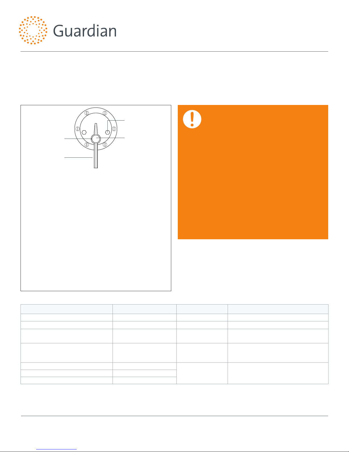
1. Loosen set screw. Remove snap cap, pointer screw,
washer, and pointer.
2. Activate emergency xture.
3. Temporarily place pointer on pointer rod and turn handle
to the left, allowing cold water to ow. Then, slowly
adjust handle to the right until the required maximum
temperature is reached. Note: Temperatures above 90°F
are not recommended. Consult a medical advisor for correct
temperature settings.
4. Once maximum temperature has been reached, remove
pointer and replace on pointer rod such that its right
edge rests against the stop screw located on the right
side of the cover.
5. Tighten set screw and replace washer, pointer screw, and
snap cap. Hold a thermometer under water ow to verify
maximum temperature has been set appropriately. Then
set desired operating temperature.
If installed on a circulated hot water system, verify the valve is piped according to Required Piping Method on page 3.
See page 5 for complete parts breakdown and parts kits.
Symptom Component Type Part No. Description
Leak at pointer rod. Packings and Gaskets
MU-5A
O-Ring
Leak between valve cover and body.
Packings and Gaskets
TM-21/125
Flange Packing
Valve outlet temperature will not mix
consistently.
Port Sleeve Assembly
TGM-1/125M or
R/125M
Port Sleeve Assembly or
Repair Kit
After cleaning or replacing port
sleeve assembly, valve will not hold
temperature.
Thermostat Group
TGM-2/125 or
R/125M
Thermostat Group or
Repair Kit
Hot water bypass into cold line. Checkstops
2/50M
Checkstop KitSupplies cannot be shut o completely. Checkstops
Leak at checkstop bonnet. Checkstops
To Reset Adjustable High Temperature Limit Stop:
Troubleshooting
Set Screw
Pointer
Snap Cap
Stop Screw
Distributed by:
Safety Emporium
PO Box 1003
Blackwood, NJ 08012
Ph: (866) 326-5412 toll-free
Fax: (856) 553-6154
esupport@safetyemporium.com
www. safetyemporium.com
 Loading...