

Page 1
Note: This is a control system which must be cleaned and maintained regularly (see Maintenance Guide and Record card included with valve shipment).
1
Guardian Equipment
1140 N North Branch St
Chicago, IL 60642
312 447 8100 telephone
312 447 8101 facsimile
gesafety.com
rev. 1215 / © 2015 Guardian Equipment
Installation, Operation and Maintenance Guide
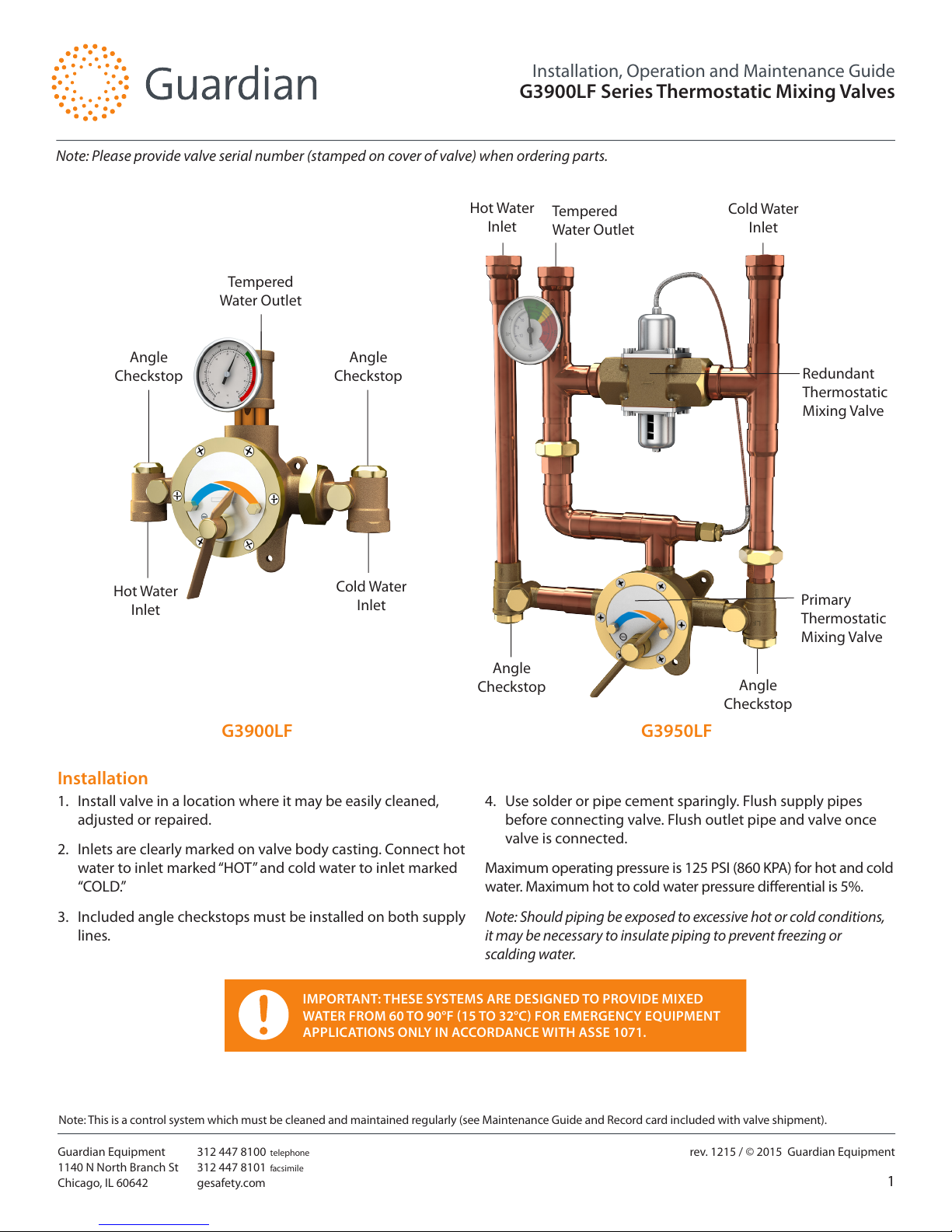
G3900LF Series Thermostatic Mixing Valves
Angle
Checkstop
Angle
Checkstop
Angle
Checkstop
Angle
Checkstop
IMPORTANT: THESE SYSTEMS ARE DESIGNED TO PROVIDE MIXED
WATER FROM 60 TO 90°F (15 TO 32°C) FOR EMERGENCY EQUIPMENT
APPLICATIONS ONLY IN ACCORDANCE WITH ASSE 1071.
Hot Water
Inlet
G3900LF
Installation
1. Install valve in a location where it may be easily cleaned,
adjusted or repaired.
2. Inlets are clearly marked on valve body casting. Connect hot
water to inlet marked “HOT” and cold water to inlet marked
“COLD.”
3. Included angle checkstops must be installed on both supply
lines.
4. Use solder or pipe cement sparingly. Flush supply pipes
before connecting valve. Flush outlet pipe and valve once
valve is connected.
Maximum operating pressure is 125 PSI (860 KPA) for hot and cold
water. Maximum hot to cold water pressure dierential is 5%.
Note: Should piping be exposed to excessive hot or cold conditions,
it may be necessary to insulate piping to prevent freezing or
scalding water.
Cold Water
Inlet
Tempered
Water Outlet
Cold Water
Inlet
Hot Water
Inlet
Tempered
Water Outlet
G3950LF
Note: Please provide valve serial number (stamped on cover of valve) when ordering parts.
Redundant
Thermostatic
Mixing Valve
Primary
Thermostatic
Mixing Valve
Page 2
Note: This is a control system which must be cleaned and maintained regularly (see Maintenance Guide and Record card included with valve shipment).
2
Guardian Equipment
1140 N North Branch St
Chicago, IL 60642
312 447 8100 telephone
312 447 8101 facsimile
gesafety.com
rev. 1215 / © 2015 Guardian Equipment
Installation, Operation and Maintenance Guide
G3900LF Series Thermostatic Mixing Valves
Adjustment and Service
Guardian thermostatic mixing valves may be easily cleaned,
adjusted and repaired. Servicing may be possible without
disconnecting valve.
Note: Thermostatic water mixing valves are regulating mechanisms
which must be regularly maintained to provide best performance.
Local water quality and usage conditions dictate cleaning frequency.
(See Maintenance Guide and Record card included with valve
shipment and reference ANSI Z358.1)
WARNING: THIS THERMOSTATIC MIXING VALVE HAS
AN ADJUSTABLE HIGH TEMPERATURE LIMIT STOP
WHICH MUST BE CHECKED. IF TEMPERATURE IS
TOO HIGH, THE INSTALLER MUST RESET THIS STOP
IMMEDIATELY. ALWAYS CHECK THE TEMPERATURE
OF THE MIXED WATER WHEN THE LEVEL
HANDLE IS TURNED TO FULL HOT. THE WATER
TEMPERATURE OF EACH INDEPENDENT OUTPUT
MUST BE CHECKED IF USING A COMBINATION
UNIT. EXCESSIVE HOT WATER TEMPERATURE IS
DANGEROUS AND MAY CAUSE SCALDING.
THE HIGH TEMPERATURE LIMIT STOP IS FACTORY
SET AT APPROXIMATELY 90°F (32°C) WITH AN
INCOMING HOT WATER SUPPLY TEMPERATURE
OF 135°F (57°C). IF THE INCOMING HOT WATER
IS HIGHER THAN 135°F (57°C), THE VALVE
(WHEN TURNED TO FULL HOT) WILL DELIVER
WATER IN EXCESS OF 90°F (32°C) AND THE HIGH
TEMPERATURE LIMIT STOP MUST BE RESET.
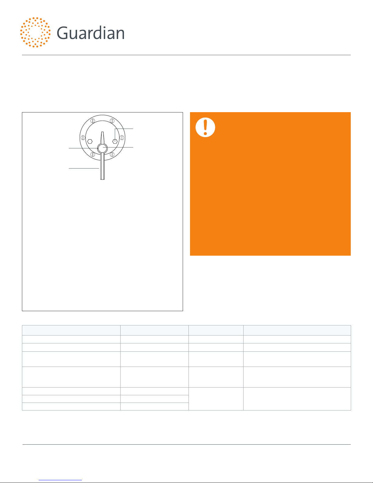
1. Loosen set screw. Remove snap cap, pointer screw,
washer, and pointer.
2. Activate emergency xture.
3. Temporarily place pointer on pointer rod and turn handle
to the left, allowing cold water to ow. Then, slowly
adjust handle to the right until the required maximum
temperature is reached. Note: Temperatures above 90°F
are not recommended. Consult a medical advisor for correct
temperature settings.
4. Once maximum temperature has been reached, remove
pointer and replace on pointer rod such that its right
edge rests against the stop screw located on the right
side of the cover.
5. Tighten set screw and replace washer, pointer screw, and
snap cap. Hold a thermometer under water ow to verify
maximum temperature has been set appropriately. Then
set desired operating temperature.
If installed on a circulated hot water system, verify the valve is piped according to Required Piping Method on page 3.
See page 5 for complete parts breakdown and parts kits.
Symptom Component Type Part No. Description
Leak at pointer rod. Packings and Gaskets
MU-5A
O-Ring
Leak between valve cover and body.
Packings and Gaskets
TM-21/125
Flange Packing
Valve outlet temperature will not mix
consistently.
Port Sleeve Assembly
TGM-1/125M or
R/125M
Port Sleeve Assembly or
Repair Kit
After cleaning or replacing port
sleeve assembly, valve will not hold
temperature.
Thermostat Group
TGM-2/125 or
R/125M
Thermostat Group or
Repair Kit
Hot water bypass into cold line. Checkstops
2/50M
Checkstop KitSupplies cannot be shut o completely. Checkstops
Leak at checkstop bonnet. Checkstops
To Reset Adjustable High Temperature Limit Stop:
Troubleshooting
Set Screw
Pointer
Snap Cap
Stop Screw
Distributed by:
Safety Emporium
PO Box 1003
Blackwood, NJ 08012
Ph: (866) 326-5412 toll-free
Fax: (856) 553-6154
esupport@safetyemporium.com
www. safetyemporium.com
Page 3

Note: This is a control system which must be cleaned and maintained regularly (see Maintenance Guide and Record card included with valve shipment).
3
Guardian Equipment
1140 N North Branch St
Chicago, IL 60642
312 447 8100 telephone
312 447 8101 facsimile
gesafety.com
rev. 1215 / © 2015 Guardian Equipment
Installation, Operation and Maintenance Guide
G3900LF Series Thermostatic Mixing Valves
Hot Supply
Cold Supply
To Hot Water Source
Hot Inlet
Cold Inlet
Hot Supply
Adjustment
Screw
Cold Supply
To Hot Water Source
Primary Thermostatic
Mixing Valve
Hot Inlet Cold Inlet
Required Piping Method
G3900LF G3950LF
This unit must be cycled each time the emergency equipment is inspected (See ANSI Z358.1, Maintenance and Training Section).
1. Set the thermostatic mixing valve to full hot. (primary
thermostatic mixing valve on the G3950LF)
2. Activate emergency equipment and allow temperature to
reach set point.
3. Turn (primary) thermostatic mixing valve to full cold and
wait ten seconds.
4. Turn (primary) thermostatic mixing valve to full hot and wait
ten seconds.
5. Verify outlet temperature does not exceed 90°F (32°C).
6. Turn (primary) thermostatic mixing valve to full cold and
wait ten seconds.
7. If necessary, adjust high temperature limit stop (see page
2). Then set (primary) mixing valve to desired operating
temperature and deactivate emergency equipment.
The G3950LF Redundant Thermostatic Mixing Valve has been factory set at 90°F (32°C). This set point can be adjusted with a 3/8” wrench
(see above). Twisting the adjustment screw clockwise will increase the temperature. Maximum set point is 100°F (38°C).
Required when hot water must be circulated to a thermostatic mixing valve that is a substantial distance from the hot water
source. Recommended hot water inlet temperature is 135°F (57°C).
Page 4

Note: This is a control system which must be cleaned and maintained regularly (see Maintenance Guide and Record card included with valve shipment).
4
Guardian Equipment
1140 N North Branch St
Chicago, IL 60642
312 447 8100 telephone
312 447 8101 facsimile
gesafety.com
rev. 1215 / © 2015 Guardian Equipment
Installation, Operation and Maintenance Guide
G3900LF Series Thermostatic Mixing Valves
To Dismantle Valve:
Shut o hot and cold water supplies to valve. Loosen set
screw. Remove snap cap, pointer screw, washer, pointer and
friction spring (see Figure 1). Remove cover screws and cover
(thermostat and gears are attached to cover).
When reassembling, insert ange packing into valve body and
replace cover and cover screws. Then replace friction spring,
pointer, washer, screw, and snap cap.
After replacing parts, pointer must be reset. Refer to page 2
instructions “To Reset Adjustable High Temperature Stop.”
To Clean Port Sleeve Assembly:
Screw (twist) the check nut away from valve body towards port
sleeve assembly. Then twist port sleeve nut away from port
sleeve assembly (towards valve body) to release port sleeve
and thimble (Figure 2).
Clean with non-corrosive agent and soft cloth. DO NOT
USE ABRASIVES. Wash parts thoroughly after cleaning and
reassemble.
Install port sleeve with elongated holes nearest the check
nut and tighten port sleeve nut against port sleeve assembly.
DO NOT OVERIGHTEN. Tighten check nut against valve body.
Driving ball on thermostat group should then be inserted into
ball socket for nal reassembly (Figure 1).
To Replace Pointer Rod With Gear:
Loosen set screw and remove snap cap, pointer screw, washer,
pointer and friction spring (Figure 1). Remove cover screws
and cover. Then remove coil sleeve stud and thermostat group.
Replace pointer rod with gear, and reassemble.
To Replace or Clean Thermostat Group:
See “To Replace Pointer Rod with Gear” (above) to disassemble
valve. Clean any collected deposits from thermostatic coil with
brush and non-corrosive cleaning solution.
Elongated Holes
(nearest the check nut)
Pointer Set
Screw
Coil Sleeve
Stud
Flange Packing
and Cover Screws
Pointer Rod
with Gear
Ball
Socket
Driving
Ball
Pointer
Friction
Spring
Cover
Elongated Holes
(nearest the check nut)
Pointer Set
Screw
Coil Sleeve
Stud
Flange Packing
and Cover Screws
Pointer Rod
with Gear
Ball
Socket
Driving
Ball
Pointer
Friction
Spring
Cover
Check Nut
Port Sleeve
Thimble
Port Sleeve
Nut
Figure 1
Figure 2
Page 5

Note: This is a control system which must be cleaned and maintained regularly (see Maintenance Guide and Record card included with valve shipment).
5
Guardian Equipment
1140 N North Branch St
Chicago, IL 60642
312 447 8100 telephone
312 447 8101 facsimile
gesafety.com
rev. 1215 / © 2015 Guardian Equipment
Installation, Operation and Maintenance Guide
G3900LF Series Thermostatic Mixing Valves
Thermostatic Mixing Valve Parts
Checkstop Parts
Repair Kits
Lockable Pointer (sux “LTR”)
Notes:
1. After installing new parts, the
adjustable high temperature limit
stop must be reset (see page 2).
2. All G3900LF and G3950LF valves
are furnished with lockable
pointers.
Repair kit Includes parts to repair both hot and cold checkstops
21 3 4 6 875 9 10 11 12 13 14
16
16
24 25
25
26
26
22
23
TM-36
Point er Se t Sc rew
171718
18
20
20
2119
15
Item Part No. Description
1 57-L Snap Cap
2 TM-29/29A Pointer Screw
3 TM-25C Pointer
4 30 Friction Spring
5 617 Dial Plate
6 TM-25D Stop Screw
7 TM-16 Cover Screws (6)
8 TM-15B/125 Cover
9 TM-21/125 Flange Packing
10 TGM-2/125 Thermostat Group
11 TGM-1/125M Port Sleeve Assembly
12 TM-3/125M Port Sleeve Nut Assembly
13 TM-8 Coil Sleeve Stud
14 TM-28A Pointer Rod
Item Part No. Description
15 MU-5A O-Ring
16 03 Lower Stem & Packing
17
011 Spring (Hot Side)
015 Spring (Cold Side)
18 MU-5A O-Ring
19 MU-4A Upper Stem
20 05 Packing
21 02 Bonnet
22 04/125 Swivel
23 09/125 Swivel Nut
24 06 Strainer Cap
25 014 Cap Packing
26 013 Screen
R/125M
Repair Kit
2/50M
Checkstop Kit
Page 6

Note: This is a control system which must be cleaned and maintained regularly (see Maintenance Guide and Record card included with valve shipment).
6
Guardian Equipment
1140 N North Branch St
Chicago, IL 60642
312 447 8100 telephone
312 447 8101 facsimile
gesafety.com
rev. 1215 / © 2015 Guardian Equipment
Installation, Operation and Maintenance Guide
G3900LF Series Thermostatic Mixing Valves
Flow Capacities
System Pressure Drop (PSI)
0
12.5
25
37.5
50
Flow Rate (GPM)
5060708090
100
110
120
130
CAUTION: ALL THERMOSTATIC MIXING VALVES HAVE
LIMITATIONS. THEY WILL NOT PROVIDE THE DESIRED
ACCURACY OUTSIDE OF THEIR FLOW CAPACITY
RANGE. CONSULT THE CAPACITY CHART AND DO NOT
OVERSIZE. MINIMUM FLOW MUST BE NO LESS THAN
SHOWN ABOVE.
IMPORTANT: THESE SYSTEMS ARE DESIGNED TO
PROVIDE MIXED WATER FROM 60 TO 90°F (15 TO
32°C) FOR EMERGENCY EQUIPMENT APPLICATIONS
ONLY IN ACCORDANCE WITH ASSE 1071.
G3900LF/G3950LF
MODEL IN OUT
MINIMUM
FLOW
(GPM)
INTERNAL
COLD WATER
BYPASS
MINIMUM
SYSTEM PRESSURE DROP
5 10 15 20 25 30 35 40 45 PSI
L/MIN .3 .7 1.0 1.4 1.7 2.1 2.4 2.8 3.1 BAR
G3900LF
G3950LF
1-1/4" 1-1/2"
3 40 53 64 72 81 90 99 108 117 126 GPM
11 151 201 242 273 307 341 374 409 443 477 L/MIN
MAXIMUM FLOW CAPACITY
Limited Warranty
Guardian Equipment warrants the original purchaser that its products will be free from defects in materials and workmanship under normal usage conditions,
and when properly installed and maintained according to manufacturer's instructions for a period of two years from date of shipment. During the warranty
period, Guardian Equipment will (at its discretion) repair or replace any product or part thereof, which shall be returned, freight prepaid to Guardian's factory
and determined by the manufacturer to be defective in materials or workmanship. There are no warranties, expressed or implied, which extend beyond verbiage
contained herein. There are no implied warranties of merchantability or tness for a particular purpose. Guardian Equipment will not be held liable for labor,
incidental or consequential damages. Any alteration or improper installation or improper use of the product will void this limited warranty.
 Loading...