

Page 1
Installation, Operation and Maintenance Guide
G3600 Series Thermostatic Mixing Valves
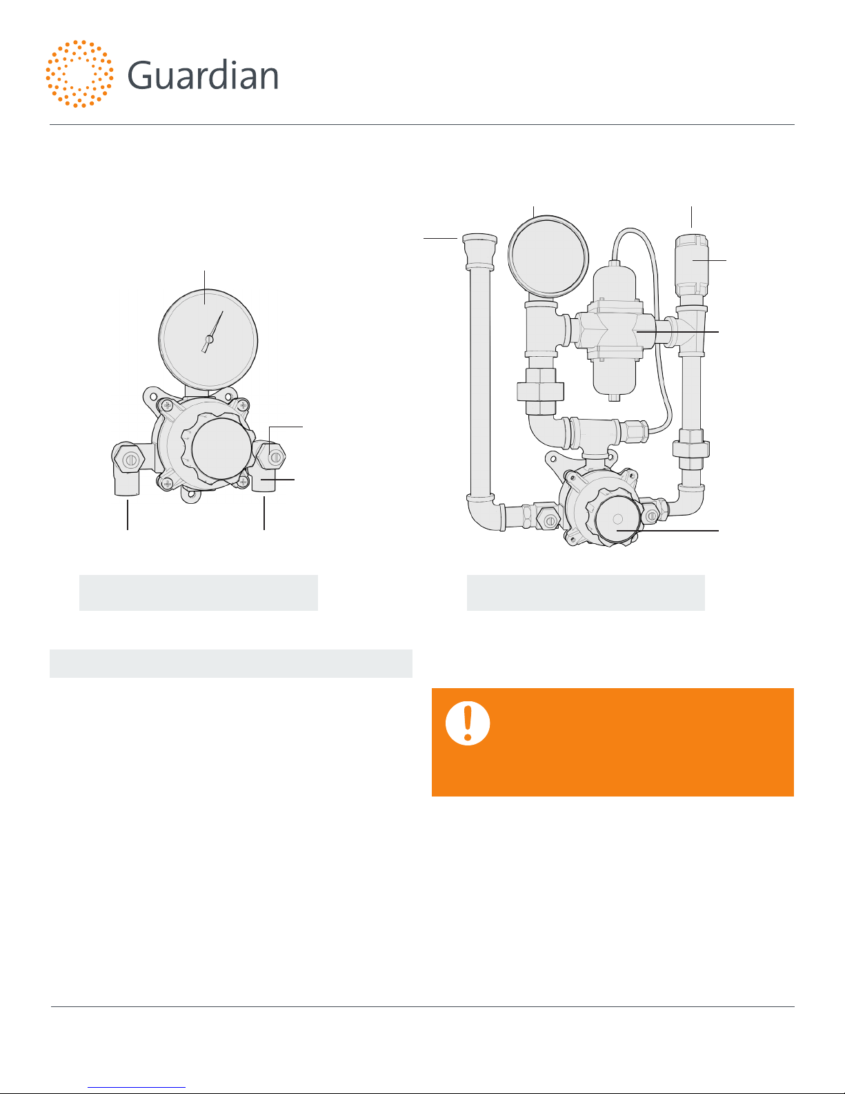
Note: Please provide valve serial number (stamped on cover of valve) when ordering parts.
Hot Water
Inlet
Thermometer
Cold Water
Inlet
Angle
Checkstops
1/2" Copper
Tube Inlets
Hot Water
Inlet
Tempered Water
Outlet
Cold Water
Inlet
Inline
Check
Redundant
Thermostatic
Mixing Valve
Primary
Thermostatic
Mixing Valve
G3600 G3650
Installation
1. Valve should be installed at a location where it can easily be
cleaned, adjusted or repaired.
2. The inlets are clearly marked on the valve body casting.
Connect the hot water into the inlet marked “HOT” and cold
water into the inlet marked “COLD.”
3. The checkstops furnished must be installed on both supply
lines as shown above.
4. Use solder or pipe cement sparingly. Supply pipes should
be flushed before the valve is connected. Flush outlet pipe
and valve as soon as it is connected.
Maximum Operating Pressure 125PSI (860 KPA) for Hot and Cold
Water. Maximum hot to cold water pressure differential is 5%.
Note: It may be necessary to recirculate the tempered water to the
face/eyewash should the piping be exposed to excessive hot or cold
conditions. Consult factory for proper piping.
Note: this is a control system which must be cleaned and maintained on a regular basis (see maintenance guide and record MGRG-1000).
IMPORTANT: THESE SYSTEMS ARE DESIGNED TO
PROVIDE MIXED WATER FROM 60 TO 90°F (15 TO
32°C) FOR EMERGENCY SHOWER APPLICATIONS
ONLY. CALL GUARDIAN EQUIPMENT FOR SYSTEMS
DESIGNED TO OPERATE AT TEMPERATURES
OUTSIDE OF THIS RANGE.
Guardian Equipment
1440 N North Branch
Chicago, IL 60642
312 447 8100 telephone
312 447 8101 facsimile
gesafety.com
rev. 0114 / © 2014 Guardian Equipment
1
Page 2
Adjustment And Service
Installation, Operation and Maintenance Guide
G3600 Series Thermostatic Mixing Valves
Guardian Equipment Thermostatic Water Mixing Valves are
simple in design and may be easily cleaned, adjusted and
repaired. If the installation is accessible, servicing may be
completed without disconnecting the valve.
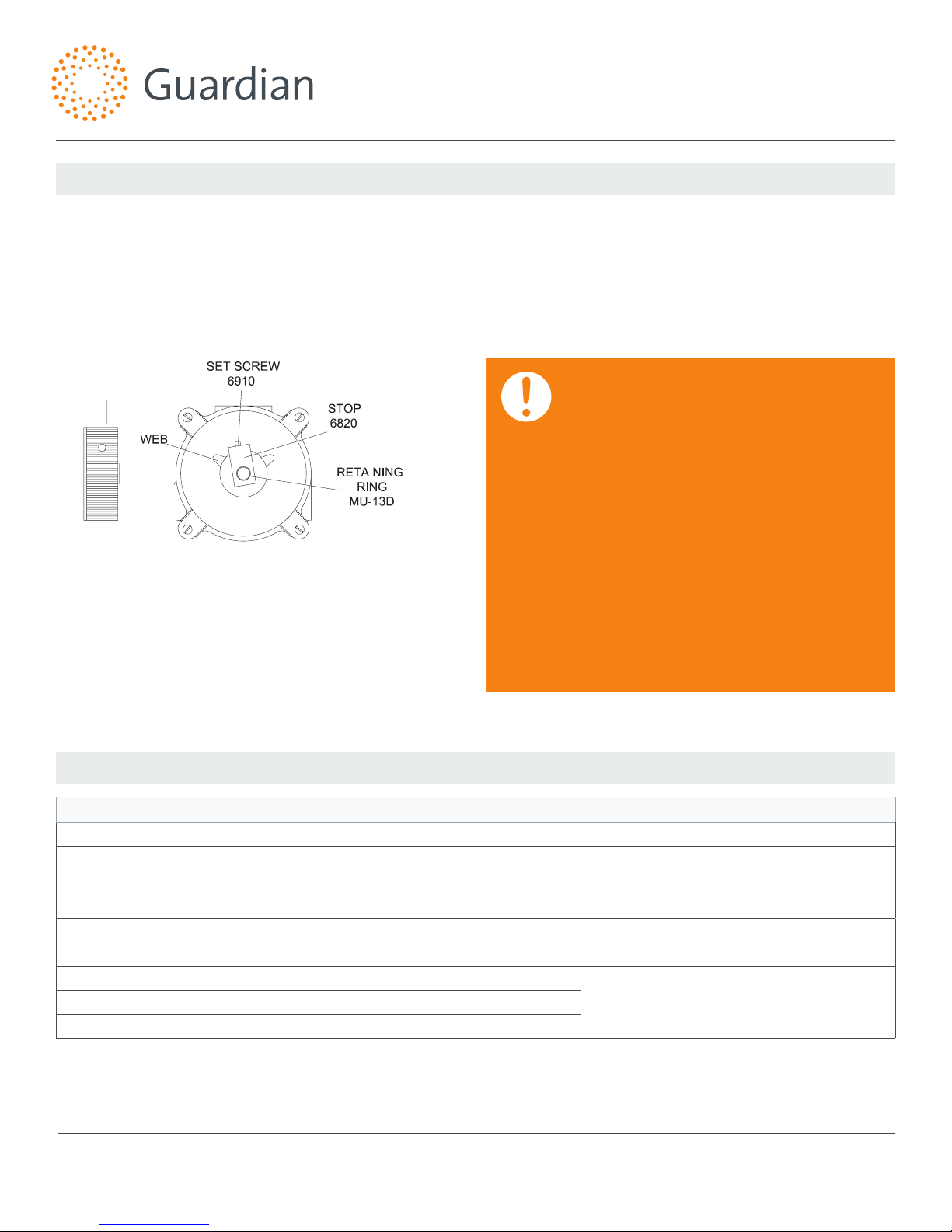
To reset adjustable high temperature limit stop:
HANDLE
68240
1. Remove 68240 handle, MU-13D retaining ring and loosen
6910 set screw, and remove 6820 stop.
2. Turn emergency fixture on.
3. Replace handle on stem and turn stem until desired
maximum temperature is reached.
4. Replace stop so it rests against the web on the LEFT side
of the cover.
5. Set operating temperature, tighten 6910 set screw and
reassemble.
Note: Thermostatic Water Mixing Valves are REGULATING mechanisms,
which must be regularly maintained to provide best performance.
Frequency of cleaning depends on quality of local water conditions
and usage. (See Maintenance Guide and Record MGRG-1000 and ANSI
Z358.1).
WARNING: THIS THERMOSTATIC MIXING VALVE
HAS AN ADJUSTABLE HIGH TEMPERATURE LIMIT
STOP WHICH MUST BE CHECKED. IF TEMPERATURE
IS TOO HIGH, THE INSTALLER MUST RESET
THIS STOP IMMEDIATELY. ALWAYS CHECK THE
TEMPERATURE OF THE MIXED WATER WHEN
THE LEVER HANDLE IS TURNED TO FULL HOT.
EXCESSIVELY HOT WATER IS DANGEROUS AND
MAY CAUSE SCALDING!
THE HIGH TEMPERATURE LIMIT STOP IS FACTORY
SET AT APPROXIMATELY 90°F (32°C) WITH AN
INCOMING HOT WATER SUPPLY TEMPERATURE
OF 140°F (60°C). IF THE INCOMING HOT WATER
ON THE JOB IS HIGHER THAN 140°F, THE VALVE
WHEN TURNED TO FULL HOT WILL DELIVER
WATER IN EXCESS OF 90°F (32°C) AND THE HIGH
TEMPERATURE LIMIT STOP MUST BE RESET BY THE
INSTALLER.
Troubleshooting
Symptom Component Type Part No. Description
Leak between valve cover and base. Packings and Gaskets 6806 Cover Gasket
Leak at pointer rod. Packings and Gaskets MU-5A O-Ring
Valve outlet temperature cannot be adjusted or
will not mix consistently.
After cleaning or replacing port sleeve assembly,
valve will not hold temperature.
Hot water bypass into cold line. Check Stops
Supplies cannot be shut off completely. Check Stops
Leak at checkstop bonnet. Check Stops
SEE PAGE 5 FOR COMPLETE PARTS BREAKDOWN AND PARTS KITS. If installed on a circulated hot water system, make certain the
valve is piped according to Guardian Equipment Required Methods of Piping (see page 3).
Note: this is a control system which must be cleaned and maintained on a regular basis (see maintenance guide and record MGRG-1000).
Guardian Equipment
1440 N North Branch
Chicago, IL 60642
312 447 8100 telephone
312 447 8101 facsimile
gesafety.com
Port Sleeve Assembly TAG-1M or
RK3600A
Thermostat Group 6810 or
RK3600A
RK3600B
RK3650B
Port Sleeve Assembly
Rebuild Kit
Thermostat Group or
Rebuild Kit
for G3600
for G3650
rev. 0114 / © 2014 Guardian Equipment
2
Page 3

Installation, Operation and Maintenance Guide
G3600 Series Thermostatic Mixing Valves
Required Method of Piping G3600 & G3650 Valves
METHOD #1: Required when hot water is to be circulated to a thermostatic mixing valve which is a substantial distance from the
hot water source.
G3600 G3650
Note: The G3650 Redundant Thermostatic Mixing Valve has been
factory set at 85°F (29°C). This set point can be field adjusted with
a 3/8” wrench (see diagram). “Clockwise” direction will increase
temperature. Maximum set point is 90°F (32°C).
Adjustment Screw
This unit must be cycled each time the emergency equipment is checked. See ANSI Z358.1, Maintenance and Training section:
• Cycle redundant thermostat valve by, limit stop (see page
2) and setting the primary thermostatic mixing valve to full
hot. (G3600 only)
• Open eye wash and check to be sure outlet temperature
does not climb above 90°F (32°C).
• Turn primary thermostatic valve to full cold and wait ten
seconds.
• Check to be sure outlet temperature does not climb above
90°F (32°C).
• Turn primary thermostatic mixing valve to full cold and wait
ten seconds.
• Set primary thermostatic mixing valve to the desired
temperature, adjust limit stop (see page 2) and close eye/face
wash.
• Turn primary thermostatic valve to full hot and wait ten
seconds.
Note: this is a control system which must be cleaned and maintained on a regular basis (see maintenance guide and record MGRG-1000).
Guardian Equipment
1440 N North Branch
Chicago, IL 60642
312 447 8100 telephone
312 447 8101 facsimile
gesafety.com
rev. 0114 / © 2014 Guardian Equipment
3
Page 4

Instructions for Dismantling Valve
Turn o hot and cold supplies to this valve. Remove four cover
screws MU-2C, lift o cover and thermostat group 6810 (g. 1).
After installing new parts, it will be necessary to reset Pointer to
obtain correct temperature range from Cold to Hot. See page 2
instructions “TO RESET ADJUSTABLE HIGH TEMPERATURE LIMIT
STOP.”
To Clean Port Sleeve Assembly:
To clean port sleeve assembly TAG-1M (g. 2.): Remove base
stud TA-5. Back o port sleeve nut 3402 as far as it will go into
base. Slide TAG-1M port sleeve assembly toward port sleeve
nut and lift out of valve base. Clean part TAG-1M with a soft
cloth; DO NOT use abrasives such as emery cloth or sandpaper.
After cleaning, wash parts in clean water and reassemble in
valve base. When reassembling port sleeve assembly BE SURE
TO INSTALL WITH SHORT SLOT END IN BASE AND LONG SLOT
END AT PORT SLEEVE NUT. Locate one set of port slots facing
directly toward front of the valve. Tighten port sleeve nut 3402
just enough to hold port sleeve in place, (do not cramp or distort port sleeve by exerting excess size pressure when tightening port sleeve nut).
Installation, Operation and Maintenance Guide
G3600 Series Thermostatic Mixing Valves
HANDLE
68240
STOP
6820
PORT SLEEVE ASSY.
TAG-1M
To Clean Thermostat Group:
To clean thermostat group 6810 (DWG 1.), remove handle
68240 by loosening lock screw and pull o. Remove stop retaining ring MU-13D and stop 6820. Remove thermostat group
by pushing rod through cover. BE CAREFUL NOT TO PULL COILS
OUT OF SHAPE. If deposit has collected on thermostat coil,
clean it o with a brush in cleaning solution and wash well
before reassembly. Cleaning solution should be non-corrosive
and grit free. To reassemble: be sure, port sleeve assembly is
in place and is working freely from side to side. Reinstall base
stud TA-5, then place thermostat group 6810 on base stud and
BE SURE DRIVING BALL ON PORT SLEEVE ASSEMBLY TAG-1M IS
INSERTED IN HOLE ON LOWER COIL BRACKET (DWG 3.) Move
thermostat back and forth to be sure all parts are free. Replace
cover on valve base, install the four cover screws, and turn on
hot and cold water supplies. See instructions below “To Reset
High Temperature Limit Stop” to properly reset limit stop.
After installation, adjustment, and cleaning, always check the
temperature of the valve when turned to full HOT per the
warning on the front page, using a thermometer. Also check
and if necessary adjust the temperature of the hot water
source. EXCESSIVELY HOT WATER (OVER 90ºF) IS DANGEROUS
AND MAY CAUSE SCALDING!!
Note: this is a control system which must be cleaned and maintained on a regular basis (see maintenance guide and record MGRG-1000).
Guardian Equipment
1440 N North Branch
Chicago, IL 60642
312 447 8100 telephone
312 447 8101 facsimile
gesafety.com
rev. 0114 / © 2014 Guardian Equipment
4
Page 5

Installation, Operation and Maintenance Guide
G3600 Series Thermostatic Mixing Valves
Valve Parts
COVER
O-RING
3009
STEM
O-RING
NU-5A
Checkstop Parts Repair Kit
STOP
6820
HANDLE
68240
B21202
LOWER STEM
AND PACKING
G3650
LVC-8A
CHECK
BONNET*
G3600
* Inlcudes parts to repair both hot and cold checkstops
Lock-Type Pointer
B05153
SPRING
RK3650B
MU-6A
LOWER
STEM w/PKG*
B21204
UPPER
STEM
MU-9A
CHECK
SPRING*
RK3600B*
Note: after installing new parts it will be
necessary to reset the adjustable high
temperature limit stop, (see page 2).
B21205
WASHER
MU-4A
UPPER
CHECK STEM
MU-5A O-RING*
B21206
PACKING
B21207
BONNET
NUT
LVC-7A
CHECK
BONNET
STEM 0-RING
MU-5A (2)
RK3600A
COVER O-RING
3009
Note: G3600 & G3650
Valves are furnished
with lockable pointers.
Note: this is a control system which must be cleaned and maintained on a regular basis (see maintenance guide and record MGRG-1000).
Guardian Equipment
1440 N North Branch
Chicago, IL 60642
312 447 8100 telephone
312 447 8101 facsimile
gesafety.com
rev. 0114 / © 2014 Guardian Equipment
5
Page 6

Flow Capacities
Maximum ow capacity gallons per minute
Pressure drop PSIG
Installation, Operation and Maintenance Guide
G3600 Series Thermostatic Mixing Valves
G3600
G3650
CAUTION: ALL THERMOSTATIC WATER MIXING
VALVES HAVE LIMITATIONS. THEY WILL NOT PROVIDE
THE DESIRED ACCURACY OUTSIDE OF THEIR FLOW
CAPACITY RANGE. CONSULT THE CAPACITY CHART
AND DO NOT OVERSIZE. MINIMUM FLOW MUST BE
NO LESS THAN SHOWN BELOW.
MODEL IN** OUT**
G3600 1/2" 1/2"
MINIMUM
FLOW
(GPM)
L/MIN .3 .7 1.0 1.4 1.7 2.1 2.4 2.8 3.1 BAR
INTERNAL
COLD WATER
BYPASS
MINIMUM
5 10 15 20 25 30 35 40 45 PSI
2 4 2.5 4 5 6 7 8 8.5 9.5 10 GPM
7.6 15 9.5 15 19 23 27 30 32 36 38 L/MIN
IMPORTANT: THESE SYSTEMS ARE DESIGNED TO
PROVIDE MIXED WATER FROM 60 TO 90°F (15 TO
32°C) FOR FACE/EYEWASH APPLICATIONS ONLY. CALL
GUARDIAN EQUIPMENT FOR SYSTEMS DESIGNED
TO OPERATE AT TEMPERATURES OUTSIDE OF THIS
RANGE.
SYSTEM PRESSURE DROP
MAXIMUM FLOW CAPACITY
**G3600 HAS 1/2" NOMINAL SWEAT CONNECTIONS.
G3650 HAS 3/4" NPT THREADED CONNECTIONS.
Limited Warranty
Guardian Equipment warrants the original purchaser that products manufactured by them, (not by others), will be free from defects in materials and
workmanship under normal conditions of use. When properly installed and maintained in accordance with Guardian Equipment’s instructions, for a period of one
year from date of shipment. During this period the Guardian Equipment will at its option repair or replace any product, or part thereof, which shall be returned,
freight prepaid, to the Guardian Equipment factory and determined by Guardian Equipment to be defective in materials or workmanship. There are no warranties,
express or implied, which extend beyond the description contained herein. There are no implied warranties of merchantability or of fitness for a particular
purpose. In no event will Guardian Equipment be liable for labor or incidental or consequential damages. Any alteration or improper installation or use of the
product will void this limited warranty.
Note: this is a control system which must be cleaned and maintained on a regular basis (see maintenance guide and record MGRG-1000).
Guardian Equipment
1440 N North Branch
Chicago, IL 60642
312 447 8100 telephone
312 447 8101 facsimile
gesafety.com
rev. 0114 / © 2014 Guardian Equipment
6
 Loading...