

Page 1
AIR-COOLED
MODELS:
5240, 5280 (7 kW NG, 6 kW LP)
5241, 5281 (9 kW NG, 10 kW LP)
5242, 5282 (13 kW NG, 13 kW LP)
5243, 5283 (15 kW NG, 16 kW LP)
5244, 5284 (15 kW NG, 16 kW LP)
DIAGNOSTIC
DIAGNOSTIC
REPAIR MANUAL
REPAIR MANUAL
AUTOMATIC STANDBY GENERATORS
www.guardiangenerators.com
Page 2
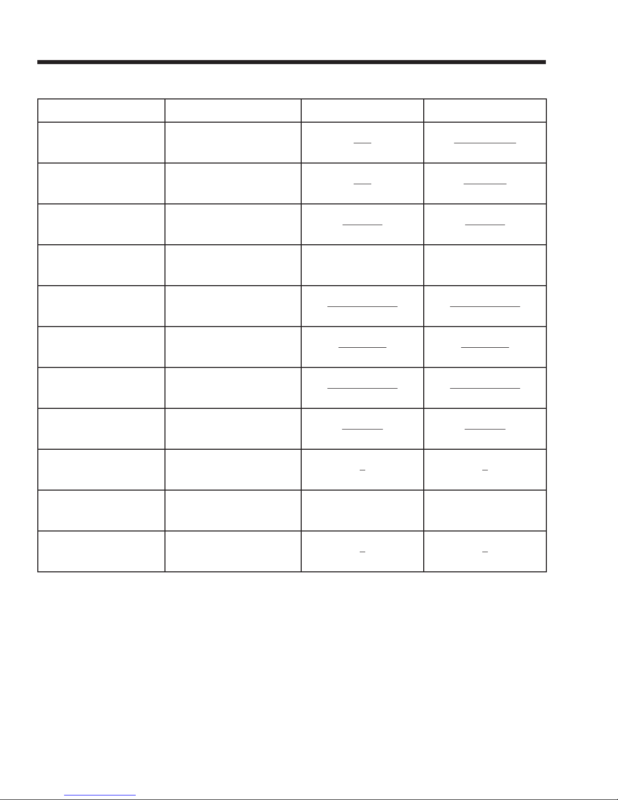
ELECTRICAL FORMULAS
TO FIND KNOWN VALUES 1-PHASE 3-PHASE
KILOWATTS (kW)
KVA
AMPERES
WATTS
NO. OF ROTOR POLES
FREQUENCY
RPM
kW (required for Motor)
Volts, Current, Power Factor
Volts, Current
kW, Volts, Power Factor
Volts, Amps, Power Factor Volts x Amps E x I x 1.73 x PF
Frequency, RPM
RPM, No. of Rotor Poles
Frequency, No. of Rotor Poles
Motor Horsepower, Efficiency
E x I
1000
E x I
1000
kW x 1000
E
2 x 60 x Frequency
RPM
RPM x Poles
2 x 60
2 x 60 x Frequency
Rotor Poles
HP x 0.746
Efficiency
E x I x 1.73 x PF
1000
E x I x 1.73
1000
kW x 1000
E x 1.73 x PF
2 x 60 x Frequency
RPM
RPM x Poles
2 x 60
2 x 60 x Frequency
Rotor Poles
HP x 0.746
Efficiency
RESISTANCE
VOLTS
AMPERES
E = VOLTS I = AMPERES R = RESISTANCE (OHMS) PF = POWER FACTOR
Volts, Amperes
Ohm, Amperes I x R I x R
Ohms, Volts
E
I
E
R
E
I
E
R
Page 3

Contents
SPECIFICATIONS..................................................... 4
Generator ................................................................ 4
Stator Winding Resistance Values/
Rotor Resistance ..................................................... 4
Engine ..................................................................... 5
Fuel Consumption ................................................... 5
Mounting Dimensions ........................................... 6-7
Major Features ........................................................ 8
PART 1 - GENERAL INFORMATION ....................... 9
1.1 Generator Identification ................................... 10
1.2 Prepackaged Installation Basics ..................... 11
Introduction ......................................................11
Selecting A Location ........................................11
Grounding The Generator ................................11
The Fuel Supply ...............................................11
The Transfer Switch / Load Center ...................11
Power Source And Load Lines .........................13
System Control Interconnections .....................13
1.3 Preparation Before Use ................................... 14
General ............................................................14
Fuel Requirements...........................................14
Fuel Consumption ............................................14
Reconfiguring The Fuel System .......................14
Engine Oil Recommendations .........................16
1.4 Testing, Cleaning and Drying........................... 16
Meters ............................................................17
The VOM ..........................................................17
Measuring AC Voltage .....................................17
Measuring DC Voltage .....................................17
Measuring AC Frequency ................................17
Measuring Current ...........................................18
Measuring Resistance .....................................18
Electrical Units .................................................19
Ohm's Law .......................................................19
Visual Inspection ..............................................20
Insulation Resistance .......................................20
The Megohmmeter...........................................20
Stator Insulation Resistance Test .....................21
Rotor Insulation Resistance Test ......................22
Cleaning The Generator...................................22
Drying The Generator ......................................22
1.5 Engine-Generator Protective Devices ............. 23
General ............................................................23
Low Battery ......................................................23
Low Oil Pressure Shutdown .............................23
High Temperature Switch .................................23
Overspeed Shutdown ......................................23
RPM Sensor Failure .........................................23
Overcrank Shutdown .......................................24
1.6 Operating Instructions ..................................... 25
Control Panel ...................................................25
To Select Automatic Operation ........................26
Manual Transfer To “Standby” And
Manual Startup ....................................26
Manual Shutdown And Retransfer
Back To “Utility” ....................................27
1.7 Automatic Operating Parameters .................... 28
Introduction ......................................................28
Automatic Operating Sequences .....................28
PART 2 - AC GENERATORS.................................. 29
2.1 Description and Components .......................... 30
Introduction ......................................................30
Engine-generator Drive System .......................30
The AC Generator ............................................30
Rotor Assembly ................................................30
Stator Assembly ...............................................31
Brush Holder And Brushes ..............................31
Other AC Generator Components ...................31
2.2 Operational Analysis ....................................... 33
Rotor Residual Magnetism...............................33
Field Boost .......................................................33
Operation .........................................................34
2.3 Troubleshooting Flowcharts ............................. 35
Problem 1 - Generator Produces Zero
Voltage or Residual Voltage .......... 35-36
Problem 2 - Generator Produces
Low Voltage at No-Load ......................37
Problem 3 - Generator Produces
High Voltage at No-Load .....................37
Problem 4 - Voltage and Frequency Drop
Excessively When Loads are Applied .38
2.3 Diagnostic Tests .............................................. 39
Introduction ......................................................39
Safety ............................................................39
Test 1 - Check Main Circuit Breaker.................39
Test 2 - Check AC Output Voltage ....................39
Test 4 - Fixed Excitation Test/Rotor
Amp Draw Test ....................................40
Test 5 - Wire Continuity ....................................41
Test 6 - Check Field Boost ...............................42
Test 7 - Testing The Stator With a VOM ...........42
Test 8 - Resistance Check of Rotor Circuit ......44
Test 9 - Check Brushes and Slip Rings ............44
Test 10 - Test Rotor Assembly .........................45
Test 11 - Check AC Output Frequency.............45
Page 1
Page 4

Test 12 - Check And Adjust Engine Governor
(Single Cylinder Units) .........................46
Test 12A - Check Stepper Motor Control
(V-twin Engine Units) ...........................46
Test 13 - Check And Adjust
Voltage Regulator ................................48
Test 14 - Check Voltage And
Frequency Under Load ........................48
Test 15 - Check For Overload Condition ..........48
Test 16 - Check Engine Condition ....................48
PART 3 - "V-TYPE PREPACKAGED
TRANSFER SWITCHES.......................... 49
3.1 Description and Components .......................... 50
General ............................................................50
Enclosure .........................................................50
Transfer Mechanism .........................................51
Transfer Relay .................................................51
Neutral Lug ......................................................52
Manual Transfer Handle ..................................52
Terminal Block .................................................52
Fuse Holder .....................................................53
3.2 Operational Analysis ....................................... 54
Utility Source Voltage Available .......................56
Utility Source Voltage Failure ..........................57
Transfer To Standby ........................................58
Transfer To Standby ........................................59
Utility Restored.................................................60
Utility Restored, Transfer Switch
De-energized .......................................61
Utility Restored,
Retransfer Back To Utility ....................62
Transfer Switch In Utility ...................................63
3.3 Troubleshooting Flow Charts ........................... 64
Introduction To Troubleshooting .......................64
Problem5-InAutomatic Mode,
No Transfer to Standby ........................64
Problem6-InAutomatic Mode, Generator
Starts When Loss of Utility Occurs,
Generator Shuts Down When Utility
Returns But There Is
No Retransfer To Utility Power .............65
Problem 7 - Blown F1 or F2 Fuse ....................65
3.4 Diagnostic Tests .............................................. 66
General ............................................................66
Test 21 - Check Voltage at
Terminal Lugs E1, E2 ..........................66
Test 22 - Check Voltage at
Standby Closing Coil C2 .....................67
Test 23 - Test Transfer Relay TR ......................67
Test 24 - Check Manual Transfer
Switch Operation .................................68
Test 25 - Test Limit Switch XB1 ........................69
Test 26 - Check 23 And 194
Wiring/Connections .............................69
Test 27- Check Voltage At
Terminal Lugs N1, N2 ..........................70
Test 28 - Check Voltage At Utility 1
And Utility 2 Ter minals .........................70
Test 29 - Check Voltage At
Utility Closing Coil C1 ..........................71
Test 30 - Check Fuses F1 And F2 ...................71
Test 31 - Test Limit Switch Xa1 ........................72
Test 32 - Continuity Test Of Wiring (C1) ...........72
Test 33 - Continuity Test Of Wiring (C2) ...........72
Test 34 - Check N1 And N2 Wiring ..................73
Test 35 - Check Transformer (Tx) .....................73
PART 4 - DC CONTROL ......................................... 75
4.1 Description and Components .......................... 76
General ............................................................76
Terminal Strip / Interconnection Ter minal .........76
Transformer (TX) ..............................................76
Circuit Board ....................................................76
AUTO-OFF-MANUAL Switch ...........................80
15 Amp Fuse....................................................80
4.2 Operational Analysis ....................................... 82
Introduction ......................................................82
Utility Source Voltage Available ........................82
Initial Dropout Of Utility Source Voltage ...........84
Utility Voltage Dropout And
Engine Cranking ..................................86
Engine Startup And Running ...........................88
Initial Transfer To The “Standby” Source ...........90
Utility Voltage Restored /
Re-transfer To Utility ............................92
Engine Shutdown ........................................... 94
4.3 Troubleshooting Flow Charts ........................... 96
Problem 8 - Engine Will Not Crank
When Utility Power Source Fails .........96
Problem 9 - Engine Will Not Crank
When AUTO-OFF-MANUAL Switch
is Set to "MANUAL" .............................96
Problem 10 - Engine Cranks
but Won't Start .....................................97
Problem 11 - Engine Starts Hard and
Runs Rough / Lacks Power .................98
Problem 12 - Engine Starts and Runs,
Then Shuts Down ................................99
Problem 13 - No Battery Charge ...................100
Problem 14 - Unit Starts and Transfer Occurs
When Utility Power is Available ........101
Page 2
Page 5

Problem 15 - Generator Starts
Immediately in Auto - No Transfer to
Standby. Utility Voltage is Present .....101
Problem 16 - 15 Amp Fuse (F1) Blown ..........102
Problem 17 - Generator Will Not Exercise .....102
Problem 18 - No Low Speed Exercise ...........102
4.4 Diagnostic Tests ............................................ 103
Introduction .................................................. 103
Test 41 - Check Position Of
AUTO-OFF-MANUAL Switch ........... 103
Test 42 - Try A Manual Start ......................... 103
Test 43 - Test AUTO-OFF-MANUAL Switch . 103
Test 44 - Check Wire 15/15A/15B/239/0
Voltage ..............................................104
Test 45 - Check 15 Amp Fuse ........................105
Test 46 - Check Battery .................................105
Test 47 - Check Wire 56 Voltage ...................106
Test 48 - Test Starter Contactor Relay
(V-twin Only) ......................................106
Test 49 - Test Starter Contactor .....................106
Test 50 - Test Starter Motor ............................107
Test 51 - Check Fuel Supply
And Pressure.....................................109
Test 52 - Check Circuit Board
Wire 14 Output ..................................110
Test 53 - Check Fuel Solenoid .......................111
Test 54 - Check Choke Solenoid
(V-twins Units Only) ...........................112
Test 55 - Check For Ignition Spark .................113
Test 56 - Check Spark Plugs ..........................114
Test 57 - Check Engine / Cylinder Leak Down
Test / Compression Test114
Test 58 - Check Shutdown Wire .....................115
Test 59 - Check And Adjust
Ignition Magnetos ..............................116
Test 60 - Check Oil Pressure Switch
And Wire 86 .......................................117
Test 61 - Check High Oil
Temperature Switch ...........................118
Test 62 - Check And Adjust Valves ................119
Test 63 - Check Fuel Regulator
(7 Kw Natural Gas Units Only) ..........117
Test 64 - Check Battery Charge Output .........120
Test 65 - Check Transformer (TX)
Voltage Output ...................................118
Test 66 - Check AC Voltage At
Battery Charger .................................121
Test 67 - Check Battery Charge
Relay (BCR) ......................................122
Test 68 - Check Battery Charge
Winding Harness ...............................122
Test 69 - Check Battery Charger Wiring .......123
Test 70 - Check Wire 18 Continuity ................123
Test 71 - Check N1 And N2 Voltage ...............123
Test 72 - Check Utility Sensing Voltage
At The Circuit Board ..........................124
Test 73 - Test Set Exercise Switch .................124
Test 75 - Check Battery Voltage Circuit ..........124
Test 76 - Check Cranking And
Running Circuits ................................124
Test 77 - Test Exercise Function ....................126
Test 78 - Check Dip Switch Settings ..............126
Test 79 - Check Idle Control Transformer
(V-twin Units Only) .............................126
Test 80 - Check LC1 & LC2 Wiring ................126
Test 81 - Check Idle Control Transformer
Primary Wiring ...................................127
PART 5 - OPERATIONAL TESTS......................... 129
5.1 System Functional Tests ................................ 130
Introduction ....................................................130
Manual Transfer Switch Operation .................130
Electrical Checks ...........................................130
Generator Tests Under Load ..........................131
Checking Automatic Operation ......................132
Setting The Exercise Timer ............................132
PART 6 - DISASSEMBLY ..................................... 133
6.1 Major Disassembly ........................................ 134
Major Disassembly .........................................134
Front Engine Access. .....................................136
Torque Requirements
(Unless Otherwise Specified) ............136
PART 7 - ELECTRICAL DATA .............................. 137
Drawing 0F7820 Wiring Diagram,
7kWHSB
Models 005240 & 005280 ................................... 138
Drawing 0F7821 Wiring Schematic,
7kWHSB
Models 005240 & 005280 ................................... 140
Drawing 0F7822 Wiring Diagram,
10, 13 & 16 kW HSB
Models 005241 & 005281
Models 005242 & 005282
Models 005243 & 005283
Models 005244 & 005284 ................................... 142
Drawing 0F7823 Schematic,
10, 13 & 16 kW HSB
Models 005241 & 005281
Models 005242 & 005282
Models 005243 & 005283
Models 005244 & 005284 ................................... 144
Drawing 0F9070 Wiring Diagram,
Transfer Switch
8 Circuit/16 Circuit ............................................... 146
Drawing 0F9775 Wiring Diagram,
Schematic
8 Circuit/16 Circuit ............................................... 147
Page 3
Page 6
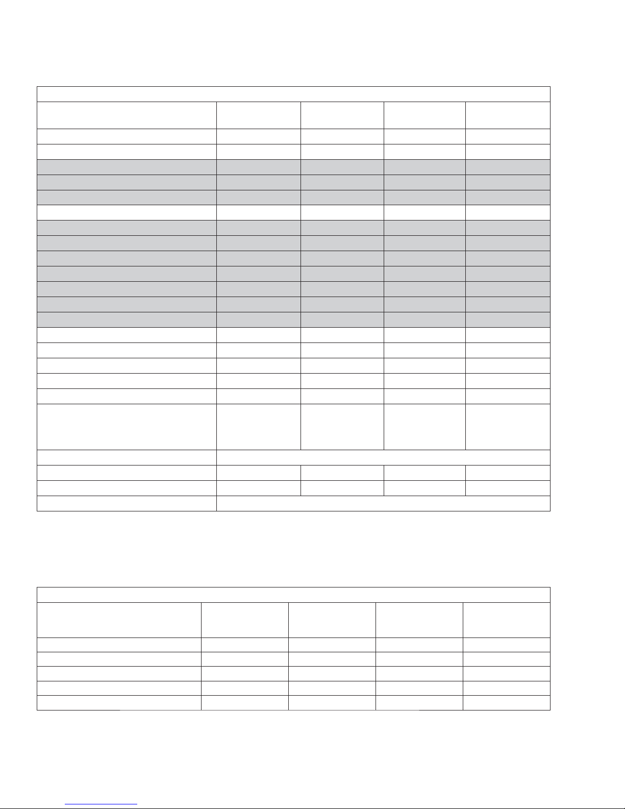
SPECIFICATIONS
GENERATOR
Model
005240 & 005280 005241 & 005281 005242 & 005282
Rated Max. Continuous Power Capacity (Watts*) 6,000 NG/7,000 LP 9,000 NG/10,000 LP 13,000 NG/13,000 LP 15,000 NG/16,000 LP
Rated Voltage 120/240 120/240 120/240 120/240
Rated Max. Continuous Load Current (Amps)
120 Volts** 50.0 NG/58.3 LP 75.0 NG/83.3 LP 108.3 NG/108.3 LP 125 NG/133.3 LP
240 Volts 25.0 NG/29.2 LP 37.5 NG/41.7 LP 54.1 NG/54.1 LP 52.5 NG/66.6 LP
Main Line Circuit Breaker 30 Amp 45 Amp 55 Amp 65 Amp
Circuits***
50A, 240V - - - 1
40A, 240V - - 1 1
30A, 240V 1 1 1 -
20A, 240V - 1 - 1
20A, 120V 1 3 3 5
15A, 120V 5 3 5 5
Phase 1 1 1 1
Number of Rotor Poles 2 2 2 2
Rated AC Frequency 60 Hz 60 Hz 60 Hz 60 Hz
Power Factor 1 1 1 1
Recommended Air Filter Part # 0C8127 Part # 0E9581 Part # 0C8127 Part # 0C8127
Battery Requirement Group 26
12 Volts and
350 Cold-cranking
Amperes Minimum
Group 26
12 Volts and
525 Cold-cranking
Amperes Minimum
Group 26
12 Volts and
525 Cold-cranking
Amperes Minimum
Battery Warming Blanket 0F6148DSRV
Weight (Unit Only) 336 Pounds 375 Pounds 425.5 Pounds 445 & 414 Pounds
Enclosure Steel/Aluminum
Normal Operating Range -20°F (-28.8°C) to 104°F (40°C)
005243 & 005283
005244 & 005284
Group 26
12 Volts and
525 Cold-cranking
Amperes Minimum
* Maximum wattage and current are subject to and limited by such factors as fuel Btu content, ambient temperature, altitude, engine power and condition, etc.Maximum power
decreases about 3.5 percent for each 1,000 feet above sea level; and also will decrease about 1 percent for each 6° C (10° F) above 16° C (60° F) ambient temperature.
** Load current values shown for 120 volts are maximum TOTAL values for two separate circuits.The maximum current in each circuit must not exceed the value stated for 240 volts.
*** Circuits to be moved from main panel to transfer switch load center must be protected by same size breaker. For example, a 15 amp circuit in main panel must be a 15 amp circuit in
transfer switch.
STATOR WINDING RESISTANCE VALUES / ROTOR RESISTANCE
Power Winding: Across 11 & 22 0.223-0.259 ohms 0.144 ohms 0.115 ohms 0.080 ohms
Power Winding: Across 33 & 44 0.223-0.259 ohms 0.144 ohms 0.115 ohms 0.080 ohms
Excitation Winding: Across2&6 1.528-1.769 ohms 1.238 ohms 1.256 ohms 1.092 ohms
Battery Charge Winding: Across 66 & 77 0.146-0.169 ohms 0.158 ohms 0.164 ohms 0.130 ohms
Rotor Resistance 11.88-13.76 ohms 11.8 ohms 12.6 ohms 22.0 ohms
Page 4
005240, 005280
(6/7 kW)
005241, 005281
(9/10 kW)
005242, 005282
(13/13 kW)
005243, 005283
005244, 005284
(15/16 kW)
Page 7
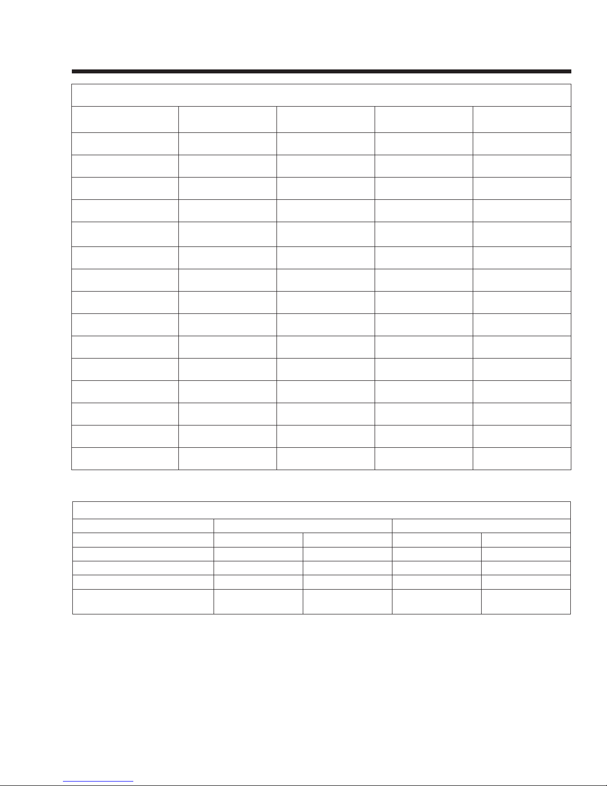
ENGINE
SPECIFICATIONS
Model 005240 & 005280 005241 & 005281 005242 & 005282
005243 & 005283
005244 & 005284
Type of Engine GH-410 GT-530 GT-990 GT-990
Number of Cylinders 1 2 2 2
Rated Horsepower 14.5 @ 3,600 rpm 18 @ 3,600 rpm 30 @ 3,600 rpm 30 @ 3,600 rpm
Displacement 410cc 530cc 992cc 992cc
Cylinder Block
Aluminum w/Cast Iron
Sleeve
Aluminum w/Cast Iron
Sleeve
Aluminum w/Cast Iron
Sleeve
Aluminum w/Cast Iron
Sleeve
Valve Arrangement Overhead Valves Overhead Valves Overhead Valves Overhead Valves
Ignition System Solid-state w/Magneto Solid-state w/Magneto Solid-state w/Magneto Solid-state w/Magneto
Recommended Spark Plug RC14YC BPR6HS RC12YC RC12YC
Spark Plug Gap 0.76 mm (0.030 inch) 0.76 mm (0.030 inch) 1.02 mm (0.040 inch) 1.02 mm (0.040 inch)
Compression Ratio 8.6:1 9.5:1 9.5:1 9.5:1
Starter 12 VDC 12 VDC 12 VDC 12 VDC
Oil Capacity Including Filter Approx. 1.5 Qts Approx. 1.7 Qts Approx. 1.7 Qts Approx. 1.7 Qts
Recommended Oil Filter Part # 070185B Par t # 070185B Part # 070185B Part # 070185B
Recommended Air Filter Part # 0C8127 Part # 0E9581 Part # 0C8127 Part # 0C8127
Operating RPM 3,600 3,600 3,600 3,600
FUEL CONSUMPTION
Model # Natural Gas* LP Vapor**
1/2 Load Full Load 1/2 Load Full Load
005240, 005280 (6/7 kW) 66 119 0.82/30 1.47/54
005241, 005281 (9/10 kW) 102 156 1.25/46 1.93/70
005242, 005282 (13/13 kW) 156 220 1.55/57 2.18/80
005243, 005283 (15/16 kW)
005244, 005284 (15/16 kW)
* Natural gas is in cubic feet per hour.
**LP is in gallons per hour/cubic feet per hour.
Values given are approximate.
173 245 1.59/59 2.51/92
Page 5
Page 8
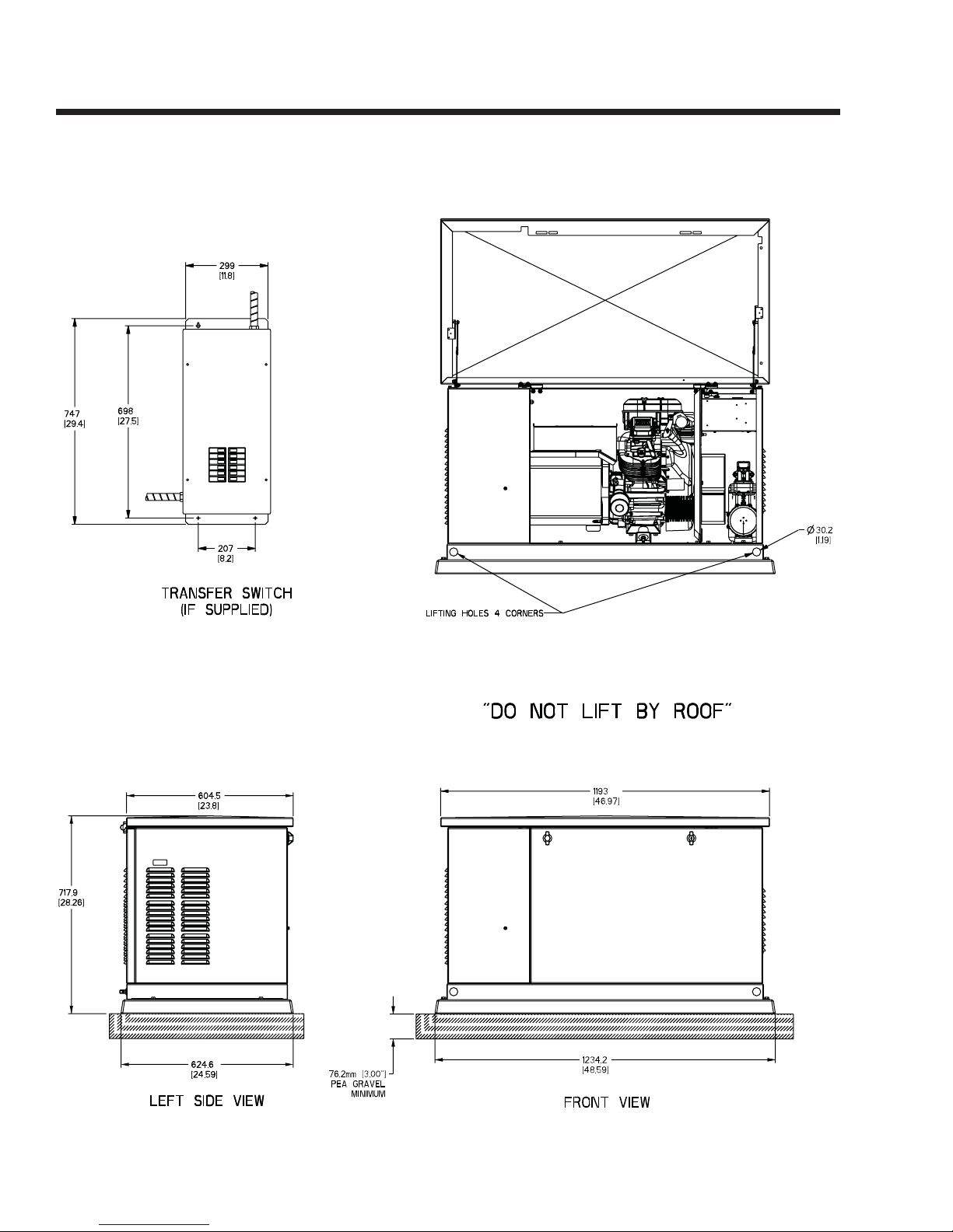
SPECIFICATIONS
MOUNTING DIMENSIONS
Page 6
Page 9
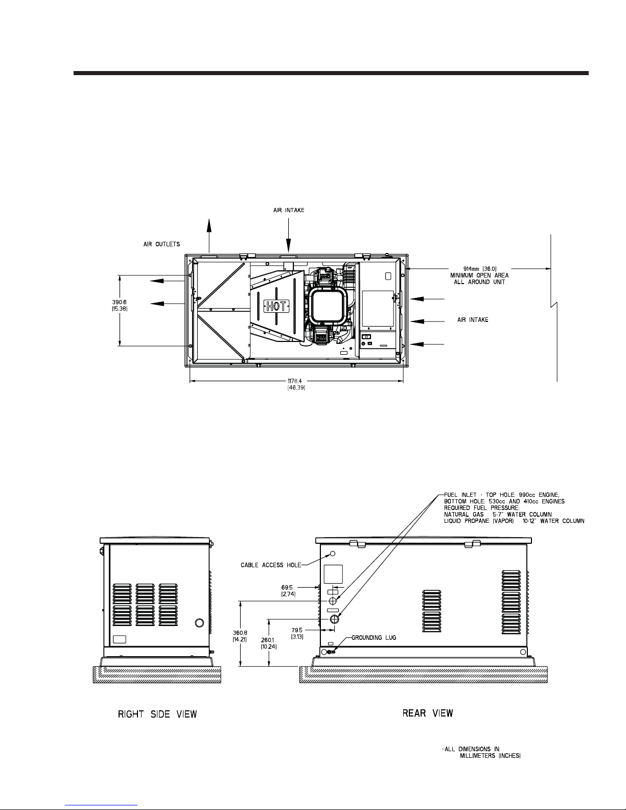
MOUNTING DIMENSIONS
SPECIFICATIONS
Page 7
Page 10
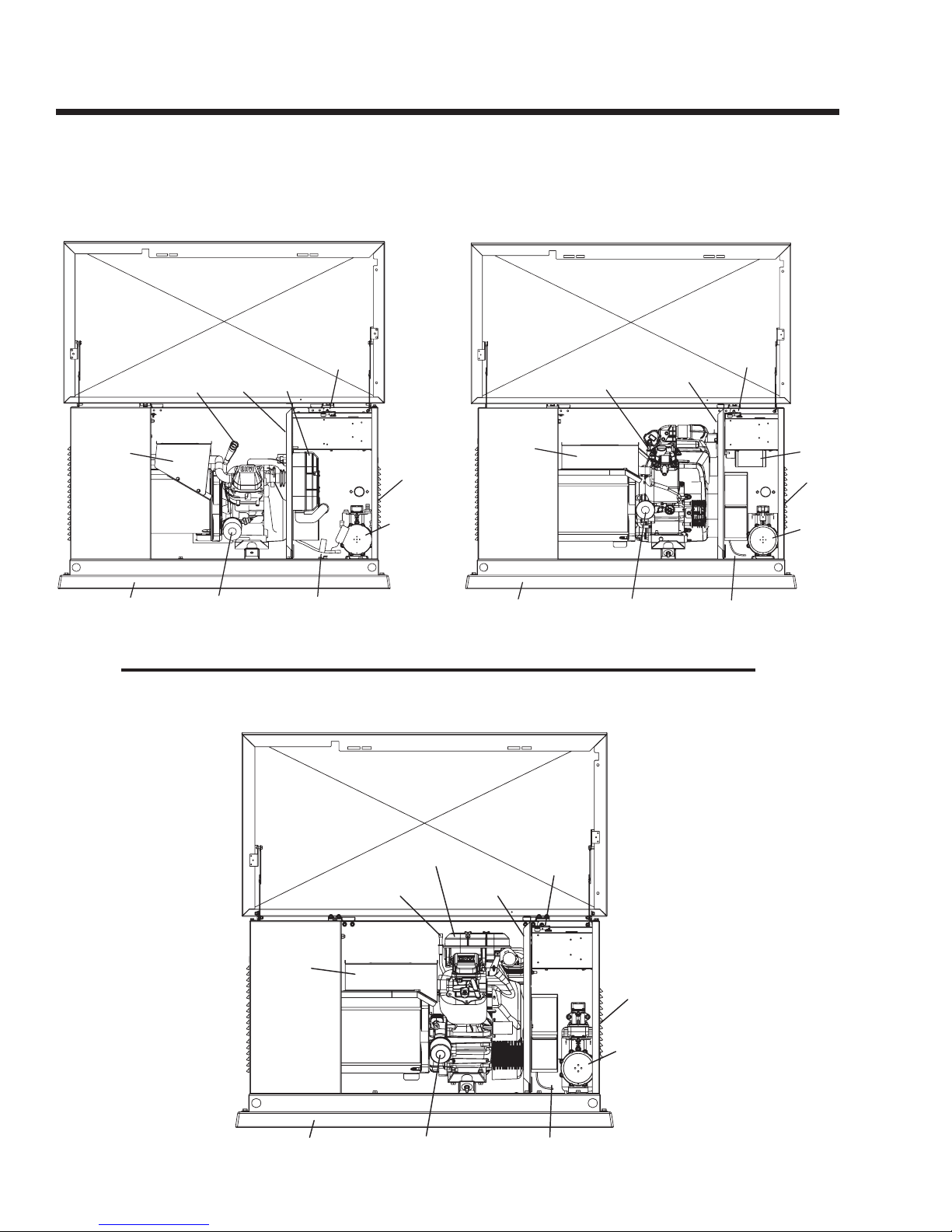
SPECIFICATIONS
MAJOR FEATURES
7 kW, Single Cylinder GH-410 Engine
Exhaust
Enclosure
Composite Base
Oil
Dipstick
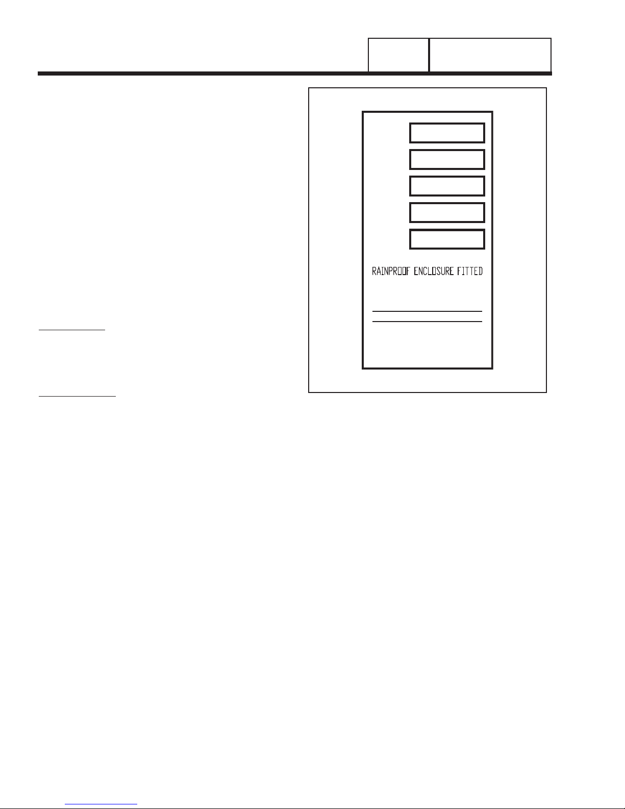
Data
Decal
Air Filter
Cover
Battery CompartmentOil Filter
Control
Panel
Fuel
Inlet
(Back)
Fuel
Regulator
Exhaust
Enclosure
Composite Base
10 kW, V-twin GT-530 Engine
Control
Oil
Dipstick
Data
Decal
Battery CompartmentOil Filter
Panel
Air Filter
Fuel
Inlet
(Back)
Fuel
Regulator
13 kW and 16 kW, V-twin GT-990 Engine
Air Filter
Cover
Oil
Dipstick
Exhaust
Enclosure
Composite Base
Data
Decal
Control
Panel
Fuel
Inlet
(Back)
Fuel
Regulator
Battery CompartmentOil Filter
Page 8
Page 11

PART 1
GENERAL
INFORMATION
Air-cooled, Prepackaged
Automatic Standby Generators
TABLE OF CONTENTS
PART TITLE PAGE
1.1 Generator Identification 10
1.2 Prepackaged Installation
Basics
1.3 Preparation Before Use 14
1.4 Testing, Cleaning and Drying 16
1.5 Engine-Generator Protective
Devices
1.6 Operating Instructions 25
1.7 Automatic Operating
Parameters
11
23
28
1.1 Generator Identification
1.2 Prepackaged Installation Basics ..................... 11
Introduction ......................................................11
Selecting A Location ........................................11
Grounding The Generator ................................11
The Fuel Supply ...............................................11
The Transfer Switch / Load Center ...................11
Power Source And Load Lines .........................13
System Control Interconnections .....................13
1.3 Preparation Before Use ................................... 14
General ............................................................14
Fuel Requirements...........................................14
Fuel Consumption ............................................14
Reconfiguring The Fuel System .......................14
Engine Oil Recommendations .........................16
1.4 Testing, Cleaning and Drying........................... 16
Meters ............................................................17
The VOM ..........................................................17
Measuring AC Voltage .....................................17
Measuring DC Voltage .....................................17
Measuring AC Frequency ................................17
Measuring Current ...........................................18
Measuring Resistance .....................................18
Electrical Units .................................................19
Ohm's Law .......................................................19
................................... 10
Visual Inspection ..............................................20
Insulation Resistance .......................................20
The Megohmmeter...........................................20
Stator Insulation Resistance Test .....................21
Rotor Insulation Resistance Test ......................22
Cleaning The Generator...................................22
Drying The Generator ......................................22
1.5 Engine-Generator Protective Devices ............. 23
General ............................................................23
Low Battery ......................................................23
Low Oil Pressure Shutdown .............................23
High Temperature Switch .................................23
Overspeed Shutdown ......................................23
RPM Sensor Failure .........................................23
Overcrank Shutdown .......................................24
1.6 Operating Instructions ..................................... 25
Control Panel ...................................................25
To Select Automatic Operation ........................26
Manual Transfer To “Standby” And
Manual Startup ....................................26
Manual Shutdown And Retransfer
Back To “Utility” ....................................27
1.7 Automatic Operating Parameters .................... 28
Introduction ......................................................28
Automatic Operating Sequences .....................28
Page 9
Page 12
SECTION 1.1
GENERATOR IDENTIFICATION
INTRODUCTION
This Diagnostic Repair Manual has been prepared
especially for the purpose of familiarizing service personnel with the testing, troubleshooting and repair of
air-cooled, prepackaged automatic standby generators. Every effort has been expended to ensure that
information and instructions in the manual are both
accurate and current. However, Generac reserves the
right to change, alter or otherwise improve the product
at any time without prior notification.
The manual has been divided into seven PARTS.
Each PART has been divided into SECTIONS. Each
SECTION consists of two or more SUBSECTIONS.
It is not our intent to provide detailed disassembly and
reassemble instructions in this manual. It is our intent
to (a) provide the service technician with an under
standing of how the various assemblies and systems
work, (b) assist the technician in finding the cause of
malfunctions, and (c) effect the expeditious repair of
the equipment.
ITEM NUMBER:
Many home standby generators are manufactured
to the unique specifications of the buyer. The Model
Number identifies the specific generator set and its
unique design specifications.
PART 1
Item #
Serial
Volts
Amps
Watts
-
1 PH, 60 HZ, RPM 3600
MAX OPERATING AMBIENT
FOR STANDBY SERVICE
0055555
1234567
120/240 AC
108.3/108.3
13000
CLASS F INSULATION
TEMP - 120F/49C
GENERAL INFORMATION
NEUTRAL FLOATING
MAX LOAD UNBALANCED - 50%
GENERAC POWER SYSTEMS
WAUKESHA, WI
MADE IN U.S.A.
SERIAL NUMBER:
Used for warranty tracking purposes.
Figure 1. A Typical Data Plate
Page 10
Page 13
GENERAL INFORMATION
PART 1
SECTION 1.2
PREPACKAGED INSTALLATION BASICS
INTRODUCTION
Information in this section is provided so that the service technician will have a basic knowledge of installation requirements for prepackaged home standby
systems. Problems that arise are often related to poor
or unauthorized installation practices.
A typical prepackaged home standby electric system
is shown in Figure 1 (next page). Installation of such a
system includes the following:
• Selecting a Location
• Grounding the generator.
• Providing a fuel supply.
• Mounting the load center.
• Connecting power source and load lines.
• Connecting system control wiring.
• Post installation tests and adjustments.
SELECTING A LOCATION
Install the generator set as close as possible to the
electrical load distribution panel(s) that will be powered by the unit, ensuring that there is proper ventilation for cooling air and exhaust gases. This will reduce
wiring and conduit lengths. Wiring and conduit not
only add to the cost of the installation, but excessively
long wiring runs can result in a voltage drop.
Control system interconnections non-prepackaged
generator consist of N1 and N2, and leads 23 and
194. Control system interconnection leads must be
run in a conduit that is separate from the AC power
leads. Recommended wire gauge size depends on
the length of the wire:
Max. Cable Length Recommended Wire Size
460 feet (140m) No. 18 AWG.
461 to 730 feet (223m) No. 16 AWG.
731 to 1,160 feet (354m) No. 14 AWG.
1,161 to 1850 feet (565m) No. 12 AWG.
GROUNDING THE GENERATOR
The National Electric Code requires that the frame
and external electrically conductive parts of the generator be property connected to an approved earth
ground. Local electrical codes may also require proper grounding of the unit. For that purpose, a grounding lug is attached to the unit. Grounding may be
accomplished by attaching a stranded copper wire of
the proper size to the generator grounding lug and to
an earth-driven copper or brass grounding-rod (electrode). Consult with a local electrician for grounding
requirements in your area.
THE FUEL SUPPLY
Prepackaged units with air-cooled engines were operated, tested and adjusted at the factory using natural
gas as a fuel. These air-cooled engine units can be
converted to use LP (propane) gas by making a few
adjustments for best operation and power.
LP (propane) gas is usually supplied as a liquid in
pressure tanks. Both the air-cooled and the liquid
cooled units require a “vapor withdrawal” type of fuel
supply system when LP (propane) gas is used. The
vapor withdrawal system utilizes the gaseous fuel
vapors that form at the top of the supply tank.
The pressure at which LP gas is delivered to the
generator fuel solenoid valve may vary considerably,
depending on ambient temperatures. In cold weather,
supply pressures may drop to “zero”. In warm weath
er, extremely high gas pressures may be encountered.
A primary regulator is required to maintain correct gas
supply pressures.
Current recommended gaseous fuel pressure at the inlet
side of the generator fuel solenoid valve is as follows:
LP NG
Minimum water column 10 inches 5 inches
Maximum water column 12 inches 7 inches
A primary regulator is required to ensure that proper
fuel supply pressures are maintained.
DANGER: LP AND NATURAL GAS ARE BOTH
Use of a flexible length of hose between the generator fuel line connection and rigid fuel lines is required.
This will help prevent line breakage that might be
caused by vibration or if the generator shifts or settles.
The flexible fuel line must be approved for use with
gaseous fuels.
Flexible fuel line should be kept as straight as possi
ble between connections. The bend radius for flexible
fuel line is nine (9) inches. Exceeding the bend radius
can cause the fittings to crack.
HIGHLY EXPLOSIVE. GASEOUS FUEL LINES
MUST BE PROPERLY PURGED AND TESTED
FOR LEAKS BEFORE THIS EQUIPMENT IS
PLACED INTO SERVICE AND PERIODICALLY
THEREAFTER. PROCEDURES USED IN
GASEOUS FUEL LEAKAGETESTS MUST
COMPLY STRICTLY WITH APPLICABLE FUEL
GAS CODES. DO NOT USE FLAME OR ANY
SOURCE OF HEAT TO TEST FOR GAS LEAKS.
NO GAS LEAKAGE IS PERMITTED. LP GAS IS
HEAVIER THAN AIR AND TENDS TO SETTLE IN
LOW AREAS. NATURAL GAS IS LIGHTER THAN
AIR AND TENDS TO SETTLE IN HIGH PLACES.
EVEN THE SLIGHTEST SPARK CAN IGNITE
THESE FUELS AND CAUSE AN EXPLOSION.
THE TRANSFER SWITCH / LOAD CENTER
A transfer switch is required by electrical code, to prevent electrical feedback between the utility and standby power sources, and to transfer electrical loads from
one power supply to another safely.
PREPACKAGED TRANSFER SWITCHES:
Instructions and information on prepackaged transfer
switches may be found in Part 3 of this manual.
Page 11
-
-
Page 14
SECTION 1.2
PREPACKAGED INSTALLATION BASICS
BAR
NEUTRAL
100A OR 200A
HOUSE MAIN
SERVICE
GROUND
PANEL BOARD
TRANSFER SWITCH)
GENERAC UL LISTED
(8, 10, 12 OR 16 CIRCUIT
PART 1
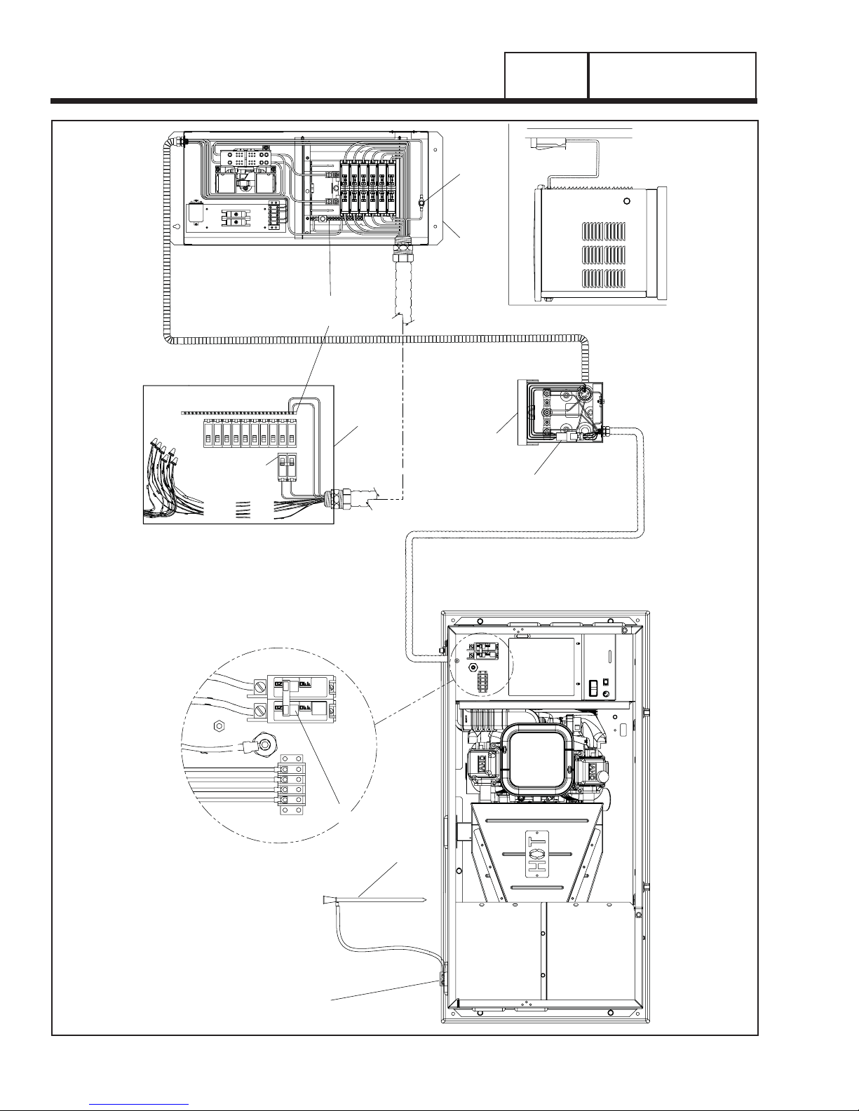
CONNECTION OF GENERATOR
TO EXTERNAL CONNECTION PANEL
GENERAL INFORMATION
TO HOUSE BRANCH
CIRCUITS SPLICED
USING WIRE NUTS
GROUND
CIRCUITS
EMERGENCY
STUD
NEUTRAL
40A OR 70A 2-POLE
CIRCUIT BREAKER
194N1 N2 23
2 POLE
EARTH
GENERATOR OUTPUT CIRCUIT BREAKER
SPIKE
CONNECTION BOX
4 PIN
EXTERNAL CUSTOMER
CONNECTOR
Page 12
Figure 1. Typical Prepackaged Installation
GENERATOR GROUND
(LOCATED ON THE REAR OF UNIT)
Page 15
GENERAL INFORMATION
PART 1
SECTION 1.2
PREPACKAGED INSTALLATION BASICS
POWER SOURCE AND LOAD LINES
The utility power supply lines, the standby (generator) supply lines, and electrical load lines must all be
connected to the proper terminal lugs in the transfer
switch. The following rules apply: In 1-phase systems
with a 2-pole transfer switch, connect the two utility
source hot lines to Transfer Switch Terminal Lugs N1
and N2. Connect the standby source hot lines (E1,
E2) to Transfer Switch Terminal Lugs E1 and E2.
Connect the load lines from Transfer Switch Terminal
Lugs T1 and T2 to the electrical load circuit. Connect
UTILITY, STANDBY and LOAD neutral lines to the
neutral block in the transfer switch.
SYSTEM CONTROL INTERCONNECTIONS
Prepackaged home standby generators are equipped
with a terminal board identified with the following terminals: (a) UTILITY 1, (b) UTILITY 2, (c) 23, and (d)
194. Prepackaged load centers house an identically
marked terminal board. When these four terminals
are properly interconnected, dropout of utility source
voltage below a preset value will result in automatic
generator startup and transfer of electrical loads to
the “Standby” source. On restoration of utility source
voltage above a preset value will result in retransfer
back to that source and generator shutdown.
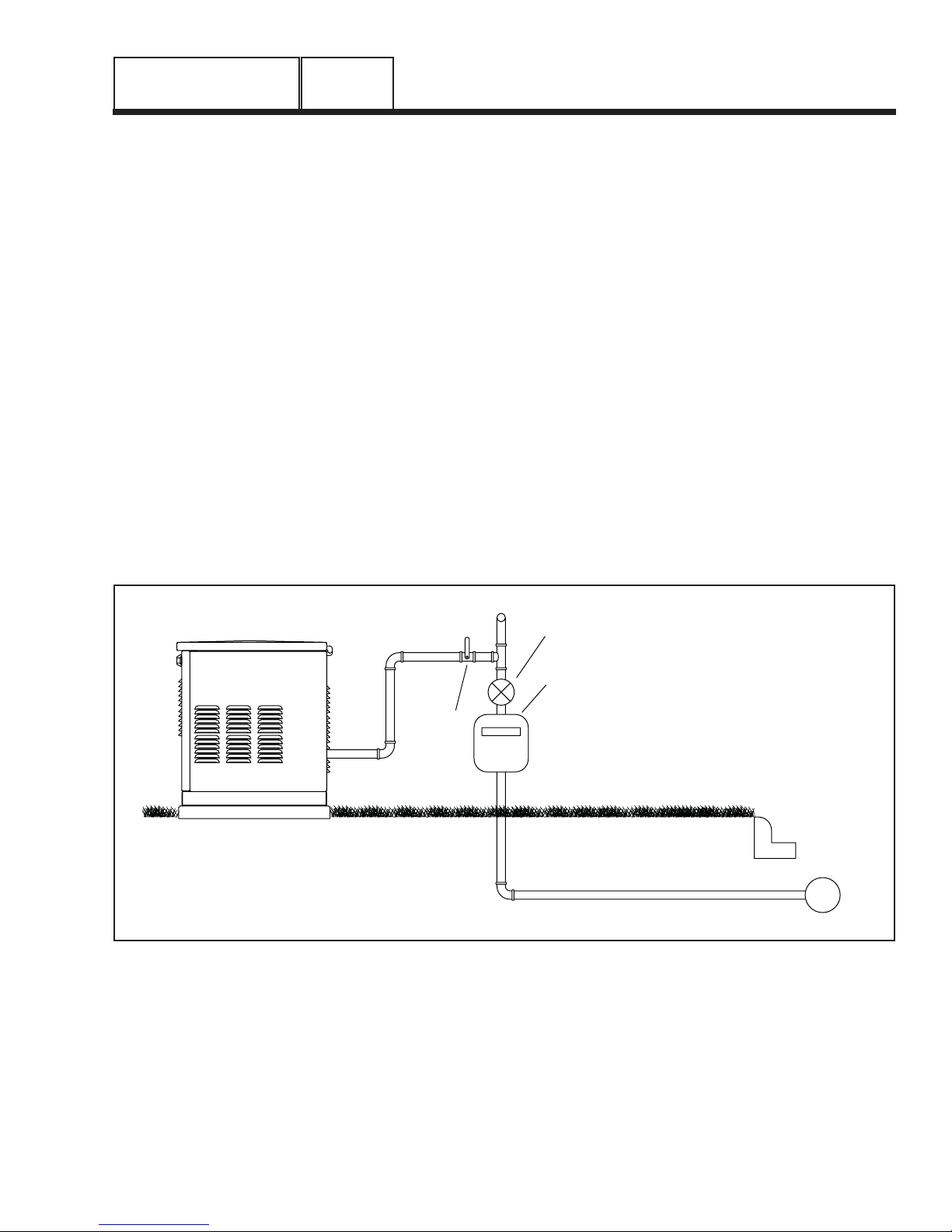
5-7" WC REGULATOR
TO HOUSEHOLD
GAS METER CAPABLE
OF PROVIDING FUEL
SAFETY
SHUT OFF
VALV E
0000001
Figure 2. Proper Fuel Installation
FLOW OF:
119,000 (6/7KW)
156,000 (9/10KW)
220,000 (13kW)
245,000 (15/16KW)
+HOUSEHOLD APPLIANCES
(BASED ON 1000 BTU/CU FT)
BTU/HOUR
}
GAS MAIN
2-5 PSI
Page 13
Page 16
SECTION 1.3
PREPARATION BEFORE USE
PART 1
GENERAL INFORMATION
GENERAL
The installer must ensure that the home standby generator has been properly installed. The system must
be inspected carefully following installation. All applicable codes, standards and regulations pertaining to
such installations must be strictly complied with. In
addition, regulations established by the Occupational
Safety and Health Administration (OSHA) must be
complied with.
Prior to initial startup of the unit, the installer must
ensure that the engine-generator has been properly
prepared for use. This includes the following:
• An adequate supply of the correct fuel must be
available for generator operation.
• The engine must be properly serviced with the rec
ommended oil.
FUEL REQUIREMENTS
With LP gas, use only the vapor withdrawal system.
This type of system uses the vapors formed above
the liquid fuel in the storage tank.
The engine has been fitted with a fuel carburetion
system that meets the specifications of the 1997
California Air Resources Board for tamper-proof dual
fuel systems. The unit will run on natural gas or LP
gas, but it has been factory set to run on natural gas.
Should the primary fuel need to be changed to LP
gas, the fuel system needs to be reconfigured. See
the Reconfiguring the Fuel System section for instruc
tions on reconfiguration of the fuel system.
Recommended fuels should have a Btu content of
at least 1,000 Btus per cubic foot for natural gas; or
at least 2,520 Btus per cubic foot for LP gas. Ask the
fuel supplier for the Btu content of the fuel.
Required fuel pressure for natural gas is 5 inches to
7 inches water column (0.18 to 0.25 psi); and for liq
uid propane, 10 inches to 12 inches of water column
(0.36 to 0.43 psi).
NOTE: All pipe sizing, construction and layout
must comply with NFPA 54 for natural gas applica
tions and NFPA 58 for liquid propane applications.
Once the generator is installed, verify that the
fuel pressure NEVER drops below four (4) inches
water column for natural gas or 10 inches water
column for liquid propane.
Prior to installation of the generator, the installer
should consult local fuel suppliers or the fire marshal
to check codes and regulations for proper installation.
Local codes will mandate correct routing of gaseous
fuel line piping around gardens, shrubs and other
landscaping to prevent any damage.
Special considerations should be given when install
ing the unit where local conditions include flooding, tornados, hurricanes, earthquakes and unstable
ground for the flexibility and strength of piping and
their connections.
Use an approved pipe sealant or joint compound on
all threaded fitting.
All installed gaseous fuel piping must be purged and
leak tested prior to initial start-up in accordance with
local codes, standards and regulations.
FUEL CONSUMPTION
The fuel consumption rates are listed in the
SPECIFICATIONS section at the front of this manual.
BTU FLOW REQUIREMENTS - NATURAL GAS:
BTU flow required for each unit based on 1000 BTU
per cubic foot.
6/7 kW — 119,000 BTU/Hour
9/10 kW — 156,000 BTU/Hour
-
13 kW — 220,000 BTU/Hour
15/16 kW — 245,000 BTU/Hour
DANGER
Gaseous fuels such as natural gas and liquid
propane (LP) gas are highly explosive. Even
the slightest spark can ignite such fuels and
cause an explosion. No leakage of fuel is permitted. Natural gas, which is lighter than air,
tends to collect in high areas. LP gas is heavi-
-
-
-
-
er than air and tends to settle in low areas.
NOTE: A minimum of one approved manual shutoff valve must be installed in the gaseous fuel
supply line. The valve must be easily accessible.
Local codes determine the proper location.
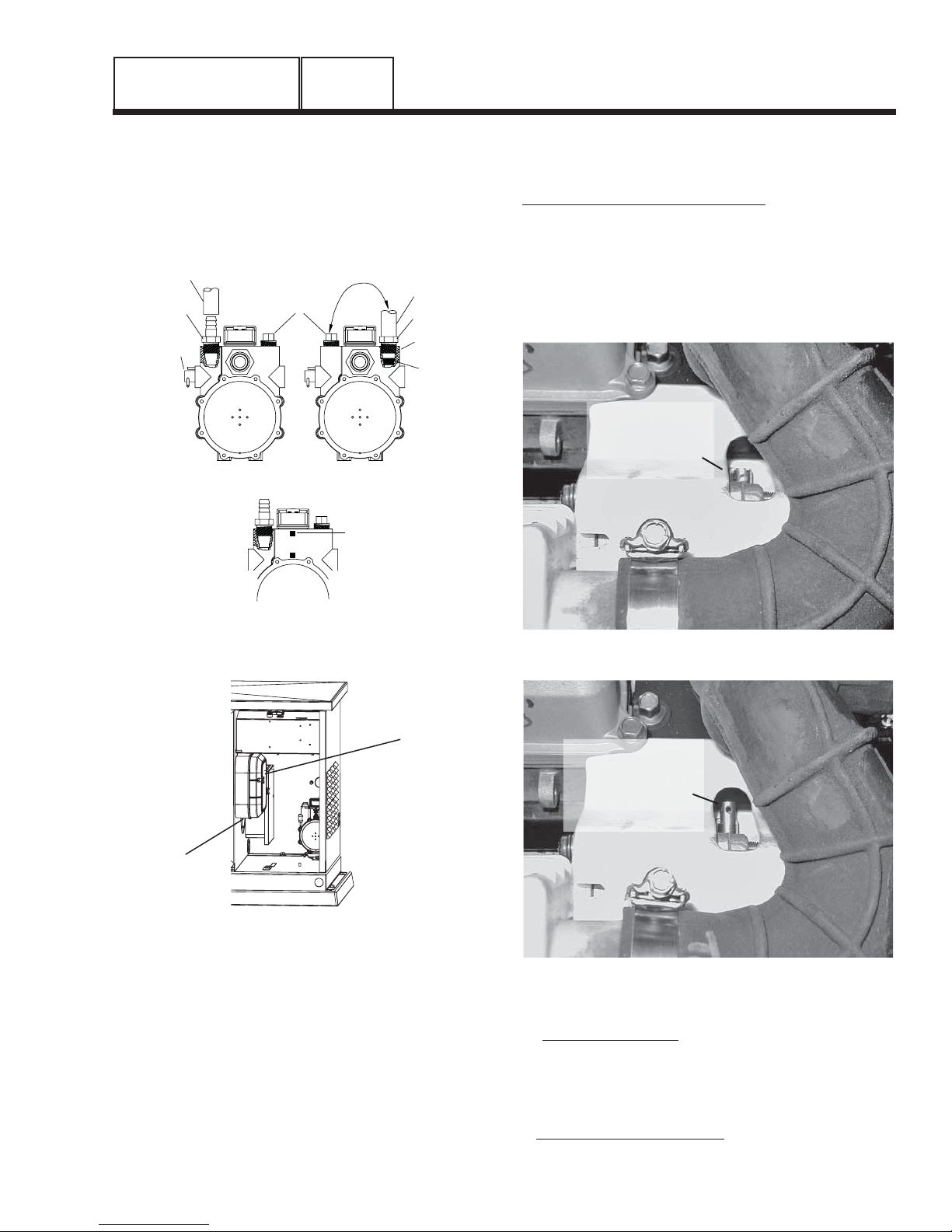
RECONFIGURING THE FUEL SYSTEM
7 KW, 410CC ENGINE:
To reconfigure the fuel system from NG to LP, follow
these steps (Figure 1):
NOTE: The primary regulator for the propane sup
ply is NOT INCLUDED with the generator. A fuel
pressure of 10 to 12 inches of water column (0.36
to 0.43 psi) to the fuel inlet of the generator must
be supplied.
1. Turn off the main gas supply (if connected).
2. Open the roof and remove the door.
3. Remove the battery (if installed).
4. Disconnect Wire 0 and Wire 14 from the gas solenoid on
top of the demand regulator.
5. Remove the carburetor fuel hose from the outlet port of
the demand regulator.
6. Remove the demand regulator by removing the fastener
that retains the regulator mounting bracket.
-
Page 14
Page 17
GENERAL INFORMATION
FUEL SELECTION
LEVER -
“IN” POSITION FOR
NATURAL GAS
FUEL SELECTION
LEVER -
“OUT” POSITION FOR
LIQUID PROPANE
(VAPOR) FUEL
PART 1
SECTION 1.3
PREPARATION BEFORE USE
7. Remove the square headed steel pipe plug from outlet port #1 and the brass hose barb fitting from outlet
port #2.
8. Refit the brass hose barb fitting to outlet port #1 and the
square headed steel pipe plug to outlet port #2.
PIPE
HOSE & PLUG
SWITCHED SIDES
LP FUEL SYSTEM
PRESSURE
TAP
FUEL HOSE
BRASS HOSE
FITTING
OUTLET
PORT
FUEL JET
FUEL HOSE
BRASS HOSE
FITTING
ADJUSTMENT
SCREW
PLUG
NG FUEL SYSTEM
12.Check for gas leakage at the pipe plug, hose connection
and fittings.
10, 13 AND 16 KW, V-TWIN ENGINES:
To reconfigure the fuel system from NG to LP, follow
these steps:
NOTE: The primary regulator for the propane sup
ply is NOT INCLUDED with the generator. A fuel
pressure of 10 to 12 inches of water column (0.36
to 0.43 psi) to the fuel inlet of the generator must
be supplied.
-
3/4” HOLE
NOTE: Use an approved pipe sealant or joint com
pound on all threaded fittings to reduce the possibility of leakage.
9. Reverse procedure Steps 1-6 to reinstall demand
regulator.
10.Take the plastic plug supplied in the poly-bag with the
generator and press it into the 3/4” hole on the bottom
of the air cleaner base (Figure 2).
11.Reverse the procedure to convert back to natural gas.
Figure 1. Demand Regulator
Figure 2. Demand Regulator
AIR
CLEANER
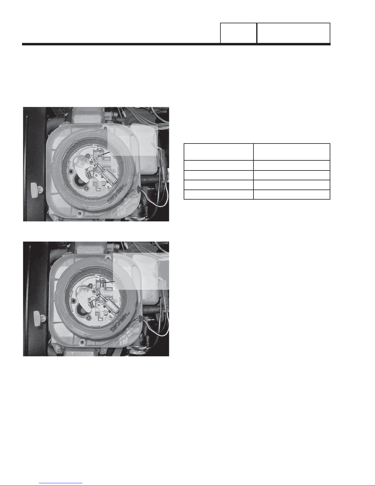
Figure 3. 10 kW, GT-530 (Inlet Hose Slid Back)
-
Figure 4. 10 kW, GT-530 (Inlet Hose Slid Back)
1. Open the roof.
2. For 10 kW units: Loosen clamp and slide back the
air inlet hose.
• Slide fuel selector on carburetor out towards the
back of the enclosure (Figures 3 and 4).
• Return the inlet hose and tighten clamp securely.
For 13 and 16 kW units: remove the air cleaner
cover.
Page 15
Page 18
SECTION 1.3
PREPARATION BEFORE USE
PART 1
GENERAL INFORMATION
• Slide the selector lever out towards the back of the
enclosure (Figures 5 and 6).
• Return the air cleaner cover and tighten the two
thumb screws.
3. Close the roof.
4. Reverse the procedure to convert back to natural gas.
FUEL SELECTION
LEVER -
“IN” POSITION FOR
NATURAL GAS
Figure 5. 13/16 kW, GT-990 (Airbox Cover Removed)
ENGINE OIL RECOMMENDATIONS
The primary recommended oil for units with aircooled, single cylinder or V-Twin engines is synthetic
oil. Synthetic oil provides easier starts in cold weather
and maximum engine protection in hot weather. Use
high quality detergent oil that meets or exceeds API
(American Petroleum Institute) Service class SG, SH,
or SJ requirements for gasoline engines. The following chart lists recommended viscosity ranges for the
lowest anticipated ambient temperatures.
Engine crankcase oil capacities for the engines cov
ered in this manual can be found in the specifications
section at the beginning of the book.
Lowest Anticipated
Ambient Temperature
Above 60° F (16° C) Use SAE 30 oil
20° to 59° F (-7° to 15° C) Use SAE 10W-30 oil
Below 20° F (-7° C) SAE 5W-20/5W-30
For all seasons Use SAE 5W-30 Synthetic oil
Oil Grade (Recommended)
-
FUEL SELECTION
LEVER -
“OUT” POSITION FOR
LIQUID PROPANE
(VAPOR) FUEL
Figure 6. 13/16 kW, GT-990 (Airbox Cover Removed)
Page 16
Page 19
GENERAL INFORMATION
PART 1
SECTION 1.4
TESTING, CLEANING AND DRYING
METERS
Devices used to measure electrical properties are
called meters. Meters are available that allow one
to measure (a) AC voltage, (b) DC voltage, (c) AC
frequency, and (d) resistance In ohms. The following
apply:
• To measure AC voltage, use an AC voltmeter.
• To measure DC voltage, use a DC voltmeter.
• Use a frequency meter to measure AC frequency In
“Hertz” or “cycles per second”.
• Use an ohmmeter to read circuit resistance, in
“ohms”.
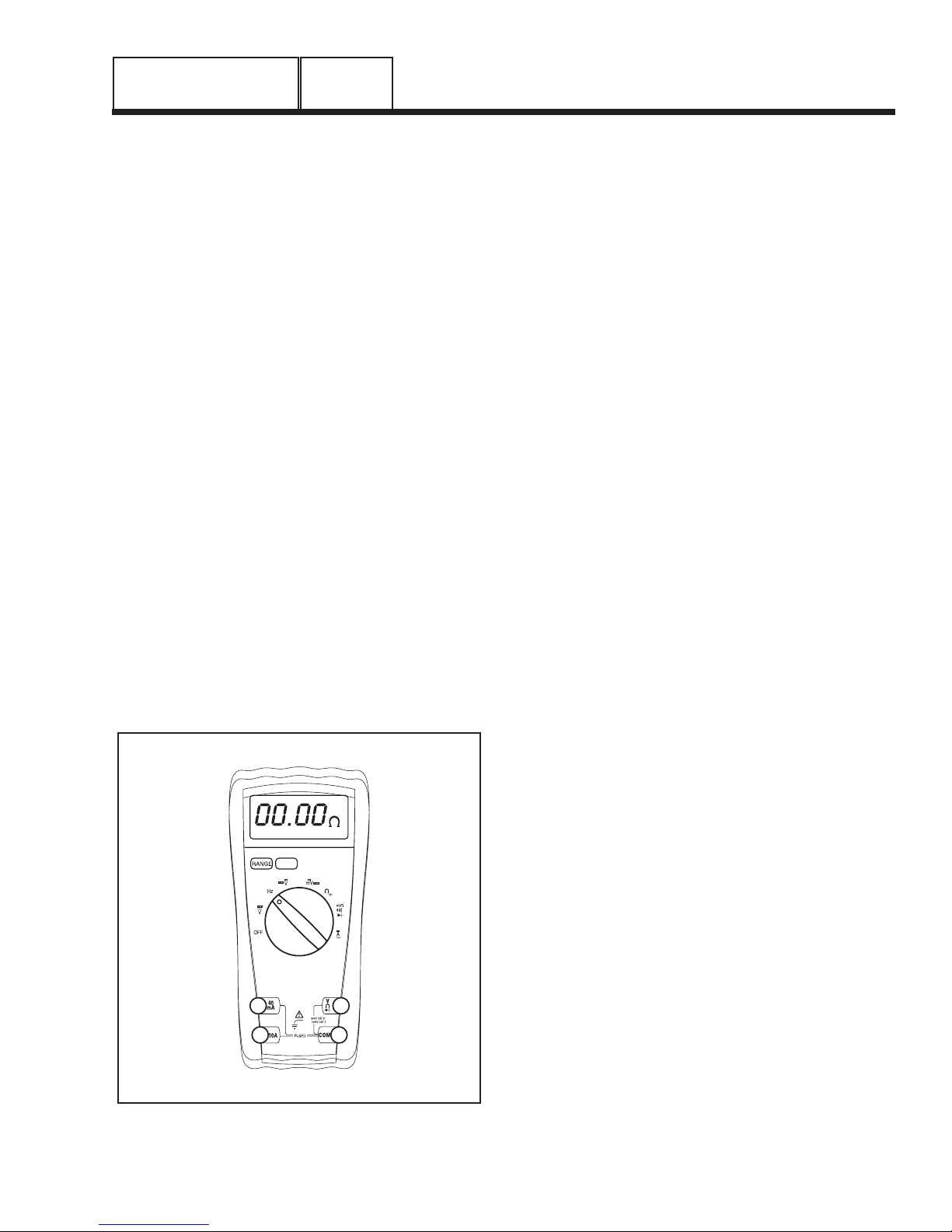
THE VOM
A meter that will permit both voltage and resistance to
be read is the “volt-ohm-milliammeter” or “VOM”.
Some VOMs are of the “analog” type (not shown).
These meters display the value being measured by
physically deflecting a needle across a graduated
scale. The scale used must be Interpreted by the user.
“Digital” VOM's (Figure 1) are also available and are
generally very accurate. Digital meters display the
measured values directly by converting the values to
numbers.
NOTE: Standard AC voltmeters react to the
AVERAGE value of alternating current. When
working with AC, the effective value is used. For
that reason a different scale is used on an AC
voltmeter. The scale is marked with the effective
or “rms” value even though the meter actually
reacts to the average value. That is why the AC
voltmeter will give an Incorrect reading if used to
measure direct current (DC).
MEASURING AC VOLTAGE
An accurate AC voltmeter or a VOM may be used to
read the generator's AC output voltage. The following
apply:
1. Always read the generator's AC output voltage only at
the unit's rated operating speed and AC frequency.
2. The generator's Voltage Regulator can be adjusted for
correct output voltage only while the unit is operating at
its correct rated speed and frequency.
3. Only an AC voltmeter may be used to measure AC
voltage. DO NOT USE A DC VOLTMETER FOR THIS
PURPOSE.
DANGER!: GENERATORS PRODUCE HIGH
AND DANGEROUS VOLTAGES. CONTACT
WITH HIGH VOLTAGE TERMINALS WILL
RESULT IN DANGEROUS AND POSSIBLY
LETHAL ELECTRICAL SHOCK.
MEASURING DC VOLTAGE
A DC voltmeter or a VOM may be used to measure
DC voltages. Always observe the following rules:
1. Always observe correct DC polarity.
a. Some VOM's may be equipped with a polar-
ity switch.
b. On meters that do not have a polarity switch,
DC polarity must be reversed by reversing
the test leads.
2. Before reading a DC voltage, always set the meter to a
higher voltage scale than the anticipated reading. If in
doubt, start at the highest scale and adjust the scale
downward until correct readings are obtained.
Figure 1. Digital VOM
3. The design of some meters is based on the “current
flow” theory while others are based on the “electron
flow” theory.
a. The “current flow” theory assumes that
direct current flows from the positive (+) to
the negative (-).
b. The “electron flow” theory assumes that cur-
rent flows from negative (-) to positive (+).
NOTE: When testing generators, the “current flow”
theory is applied. That is, current is assumed to
flow from positive (+) to negative (-).
MEASURING AC FREQUENCY
The generator's AC output frequency is proportional
to Rotor speed. Generators equipped with a 2-pole
Rotor must operate at 3600 rpm to supply a frequency
of 60 Hertz. Units with 4-pole Rotor must run at 1800
rpm to deliver 60 Hertz.
Page 17
Page 20
SECTION 1.4
TESTING, CLEANING AND DRYING
PART 1
GENERAL INFORMATION
Correct engine and Rotor speed is maintained by an
engine speed governor. For models rated 60 Hertz,
the governor is generally set to maintain a no-load frequency of about 62 Hertz with a corresponding output
voltage of about 124 volts AC line-to-neutral. Engine
speed and frequency at no-load are set slightly high
to prevent excessive rpm and frequency droop under
heavy electrical loading.
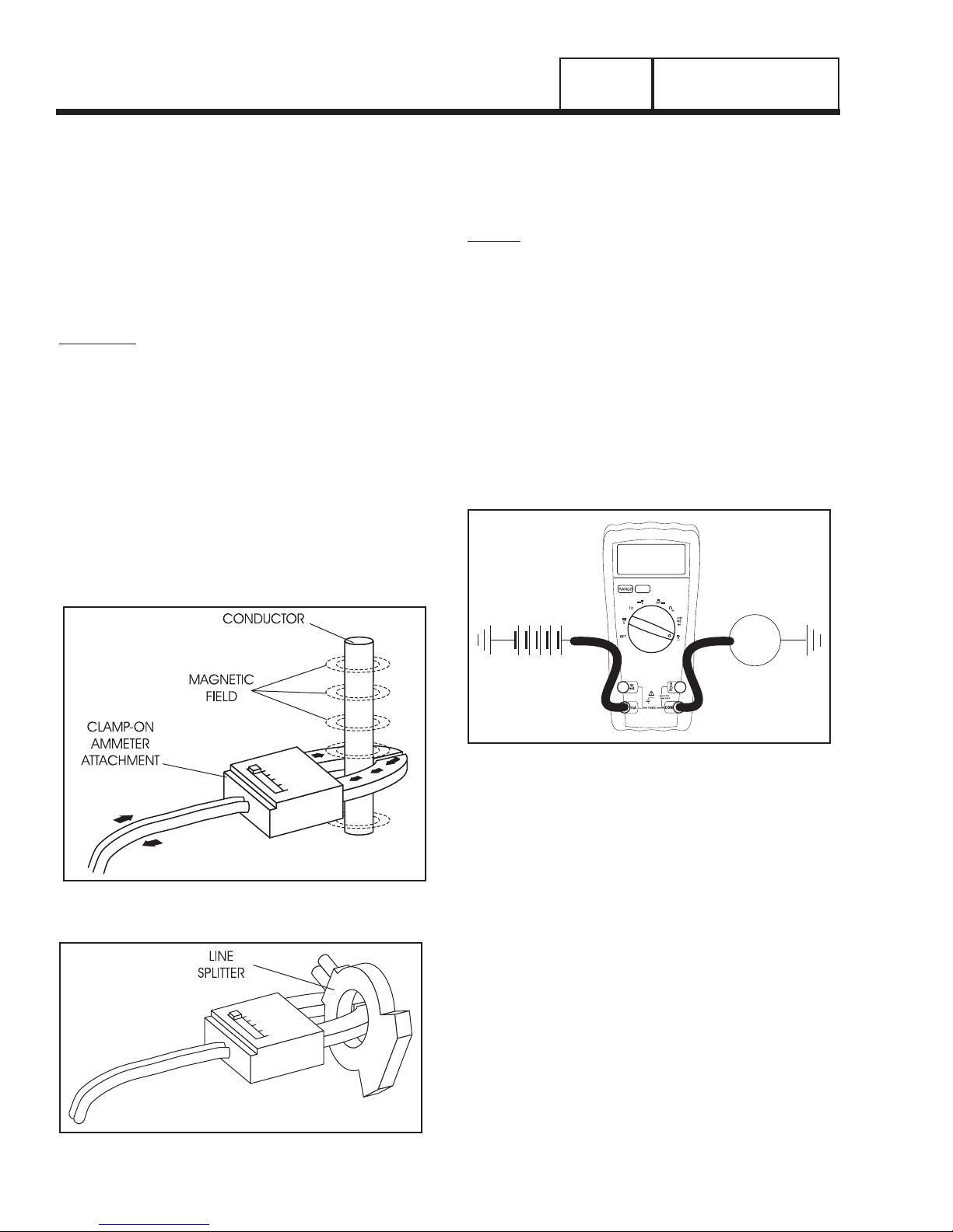
MEASURING CURRENT
CLAMP-ON:
To read the current flow, in AMPERES, a clamp-on
ammeter may be used. This type of meter indicates
current flow through a conductor by measuring the
strength of the magnetic field around that conductor.
The meter consists essentially of a current transformer with a split core and a rectifier type instrument
connected to the secondary. The primary of the current transformer is the conductor through which the
current to be measured flows. The split core allows
the Instrument to be clamped around the conductor
without disconnecting it.
Current flowing through a conductor may be mea
sured safely and easily. A line-splitter can be used
to measure current in a cord without separating the
conductors.
NOTE: If the physical size of the conductor or
ammeter capacity does not permit all lines to be
measured simultaneously, measure current flow
in each individual line. Then, add the Individual
readings.
IN-LINE:
Alternatively, to read the current flow in AMPERES,
an in-line ammeter may be used. Most Digital Volt
Ohm Meters (VOM) will have the capability to measure amperes.
This usually requires the positive meter test lead to be
connected to the correct amperes plug, and the meter
to be set to the amperes position. Once the meter is
properly set up to measure amperes the circuit being
measured must be physically broken. The meter will
be in-line or in series with the component being mea
sured.
In Figure 4 the control wire to a relay has been
removed. The meter is used to connect and supply
voltage to the relay to energize it and measure the
amperes going to it.
-
1.00 A
-
Figure 2. Clamp-On Ammeter
BATTERY
+-
Figure 4. A VOM as an In-line meter
RELAY
MEASURING RESISTANCE
The volt-ohm-milliammeter may be used to measure
the resistance in a circuit. Resistance values can be
very valuable when testing coils or windings, such as
the Stator and Rotor windings.
When testing Stator windings, keep in mind that the
resistance of these windings is very low. Some meters
are not capable of reading such a low resistance and
will simply read CONTINUITY.
If proper procedures are used, the following condi
tions can be detected using a VOM:
• A “short-to-ground” condition in any Stator or Rotor
winding.
• Shorting together of any two parallel Stator wind
ings.
• Shorting together of any two isolated Stator wind
ings.
• An open condition in any Stator or Rotor winding.
-
-
-
Figure 3. A Line-Splitter
Page 18
Page 21
GENERAL INFORMATION
PART 1
SECTION 1.4
TESTING, CLEANING AND DRYING
Component testing may require a specific resistance value or a test for INFINITY or CONTINUITY.
Infinity is an OPEN condition between two electrical
points, which would read as no resistance on a VOM.
Continuity is a closed condition between two electrical
points, which would be indicated as very low resistance or “ZERO” on a VOM.
ELECTRICAL UNITS
AMPERE:
The rate of electron flow in a circuit is represented
by the AMPERE. The ampere is the number of electrons flowing past a given point at a given time. One
AMPERE is equal to just slightly more than six thousand million billion electrons per second.
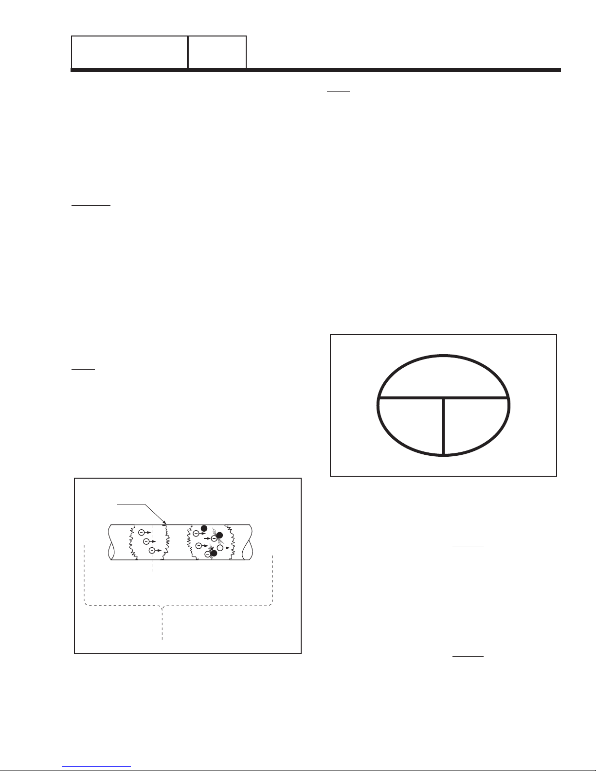
With alternating current (AC), the electrons flow first
in one direction, then reverse and move in the oppo
site direction. They will repeat this cycle at regular
intervals. A wave diagram, called a “sine wave” shows
that current goes from zero to maximum positive
value, then reverses and goes from zero to maximum
negative value. Two reversals of current flow is called
a cycle. The number of cycles per second is called
frequency and is usually stated in “Hertz”.
VOLT:
The VOLT is the unit used to measure electrical
PRESSURE, or the difference in electrical potential
that causes electrons to flow. Very few electrons will
flow when voltage is weak. More electrons will flow as
voltage becomes stronger. VOLTAGE may be considered to be a state of unbalance and current flow as
an attempt to regain balance. One volt is the amount
of EMF that will cause a current of 1 ampere to flow
through 1 ohm of resistance.
OHM:
The OHM is the unit of RESISTANCE. In every circuit
there is a natural resistance or opposition to the flow
of electrons. When an EMF is applied to a complete
circuit, the electrons are forced to flow in a single
direction rather than their free or orbiting pattern. The
resistance of a conductor depends on (a) its physical
makeup, (b) its cross-sectional area, (c) its length,
and (d) its temperature. As the conductor's temperature increases, its resistance increases in direct proportion. One (1) ohm of resistance will permit one (1)
ampere of current to flow when one (1) volt of electromotive force (EMF) is applied.
OHM'S LAW
A definite and exact relationship exists between
VOLTS, OHMS and AMPERES. The value of one can
be calculated when the value of the other two are
-
known. Ohm's Law states that in any circuit the current
will increase when voltage increases but resistance
remains the same, and current will decrease when
resistance Increases and voltage remains the same.
VOLTS
(E)
AMPS
(I)
OHMS
(R)
Conductor of a
Circuit
OHM - Unit measuring resistance
-
AMPERE - Unit measuring rate of
Figure 5. Electrical Units
current flow (number of electrons
past a given point)
VOLT - Unit measuring force or
difference in potential
causing current flow
or opposition to flow
+
Figure 6. Ohm's Law
If AMPERES is unknown while VOLTS and OHMS are
known, use the following formula:
=
AMPERES
VOLTS
OHMS
VOLTS
Page 19
AMPERES =
If VOLTS is unknown while AMPERES and OHMS are
known, use the following formula:
VOLTS = AMPERES x OHMS
If OHMS is unknown but VOLTS and AMPERES are
known, use the following:
OHMS
Page 22
SECTION 1.4
TESTING, CLEANING AND DRYING
PART 1
GENERAL INFORMATION
VISUAL INSPECTION
When it becomes necessary to test or troubleshoot a
generator, it is a good practice to complete a thorough
visual inspection. Remove the access covers and look
closely for any obvious problems. Look for the following:
• Burned or broken wires, broken wire connectors,
MINIMUM INSULATION
RESISTANCE =
(in “Megohms”)
damaged mounting brackets, etc.
• Loose or frayed wiring insulation, loose or dirty con
nections.
• Check that all wiring is well clear of rotating parts.
• Verify that the Generator properly connected for the
correct rated voltage. This is especially important on
new installations. See Section 1.2, “AC Connection
Systems”.
• Look for foreign objects, loose nuts, bolts and other
fasteners.
• Clean the area around the Generator. Clear away
paper, leaves, snow, and other objects that might
blow against the generator and obstruct its air
openings.
GENERATOR RATED VOLTS
__________________________
1000
+1
INSULATION RESISTANCE
Use a megger power setting of 500 volts. Connect
one megger test lead to the junction of all stator
leads, the other test lead to frame ground on the stator can. Read the number of megohms on the meter.
The MINIMUM acceptable megger reading for stators
may be calculated using the following formula:
EXAMPLE: Generator is rated at 120 volts AC.
Divide “120” by “1000” to obtain “0.12”. Then add
“1” to obtain “1.12” megohms. Minimum Insulation
resistance for a 120 VAC stator is 1.12 megohms.
If the stator insulation resistance is less than the cal
culated minimum resistance, clean and dry the stator.
Then, repeat the test. If resistance is still low, replace
the stator.
Use the Megger to test for shorts between isolated
windings as outlined “Stator Insulation Tests”.
Also test between parallel windings. See “Test
Between Windings” on next page.
TESTING ROTOR INSULATION:
Apply a voltage of 500 volts across the rotor posi-
tive (+) slip ring (nearest the rotor bearing), and
a clean frame ground (i.e. the rotor shaft). DO
NOT EXCEED 500 VOLTS AND DO NOT APPLY
VOLTAGE LONGER THAN 1 SECOND. FOLLOW
THE MEGGER MANUFACTURER’S INSTRUCTIONS
CAREFULLY.
ROTOR MINIMUM INSULATION RESISTANCE:
1.5 megohms
-
The insulation resistance of stator and rotor windings
is a measurement of the integrity of the insulating
materials that separate the electrical windings from
the generator steel core. This resistance can degrade
over time or due to such contaminants as dust, dirt,
oil, grease and especially moisture. In most cases,
failures of stator and rotor windings is due to a breakdown in the insulation. And, in many cases, a low insulation resistance is caused by moisture that collects
while the generator is shut down. When problems are
caused by moisture buildup on the windings, they can
usually be corrected by drying the windings. Cleaning
and drying the windings can usually eliminate dirt and
moisture built up in the generator windings.
THE MEGOHMMETER
GENERAL:
A megohmmeter, often called a “megger”, consists of
a meter calibrated in megohms and a power supply.
Use a power supply of 500 volts when testing stators
or rotors. DO NOT APPLY VOLTAGE LONGER THAN
ONE (1) SECOND.
TESTING STATOR INSULATION:
All parts that might be damaged by the high meg-
ger voltages must be disconnected before testing.
Isolate all stator leads (Figure 8) and connect all of
the stator leads together. FOLLOW THE MEGGER
MANUFACTURER’S INSTRUCTIONS CAREFULLY.
Page 20
CAUTION: Before attempting to measure
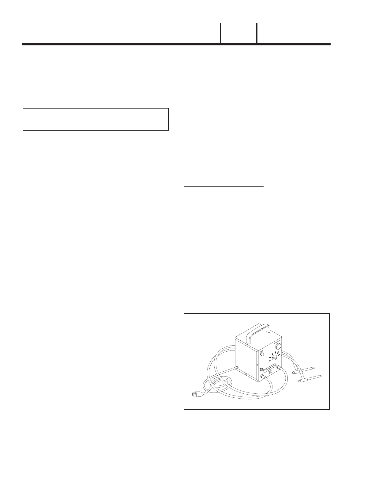
HI-POT TESTER:
A “Hi-Pot” tester is shown in Figure 7. The model
shown is only one of many that are commercially
available. The tester shown is equipped with a voltage
Insulation resistance, first disconnect and
Isolate all leads of the winding to be tested.
Electronic components, diodes, surge protectors, relays, voltage regulators, etc., can be
destroyed if subjected to high megger voltages.
Figure 7. One Type of Hi-Pot Tester
Page 23
GENERAL INFORMATION
PART 1
SECTION 1.4
TESTING, CLEANING AND DRYING
selector switch that permits the power supply voltage
to be selected. It also mounts a breakdown lamp that
will illuminate to indicate an insulation breakdown during the test.
STATOR INSULATION RESISTANCE TEST
GENERAL:
Units with air-cooled engines are equipped with (a)
dual stator AC power windings, (b) an excitation
or DPE winding, and (c) a battery charge winding.
Insulation tests of the stator consist of (a) testing all
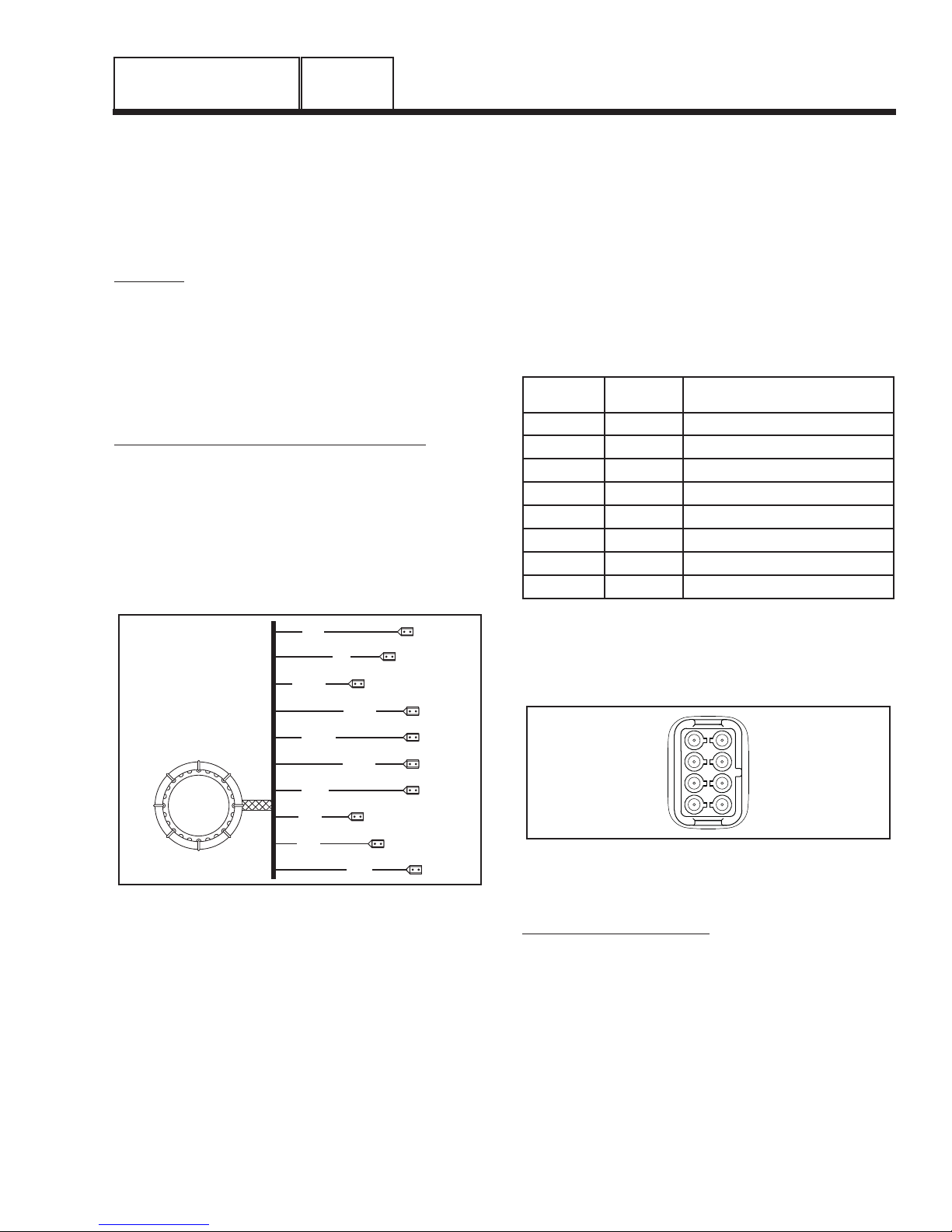
windings to ground, (b) testing between isolated windings, and (c) testing between parallel windings. Figure
8 is a pictorial representation of the various stator
leads on units with air-cooled engine.
TESTING ALL STATOR WINDINGS TO GROUND:
1. Disconnect stator output leads 11 and 44 from the generator main line circuit breaker.
2. Remove stator output leads 22 and 33 from the neutral
connection and separate the two leads.
3. Disconnect C2 Connector from the side of the control
panel. The C2 Connector is the closest to the back
panel (see Figure 9, Section 6.1).
c.Turn the tester switch ON and observe the
breakdown lamp on tester. DO NOT APPLY
VOLTAGE LONGER THAN 1 SECOND. After
one (1) second, turn the tester switch OFF.
If the breakdown lamp comes on during the one-sec
ond test, the stator should be cleaned and dried. After
cleaning and drying, repeat the insulation test. If, after
cleaning and drying, the stator fails the second test,
the stator assembly should be replaced.
6. Now proceed to the C2 Connector. Each winding will be
individually tested for a short to ground. Insert a large
paper clip (or similar item) into the C2 Connector at the
following pin locations:
Pin
Location
1 77 Battery Charge
2 66 Battery Charge
3 22 Sense Lead Power
4 11 Sense Lead Power
5 6 Excitation
6 2 Excitation
7 0 Ground
8 4 Positive to Brush
Wire
Number
Winding
-
2
6
11P
11S
22P
22S
33
44
66
77
Figure 8. Stator Winding Leads
4. Connect the terminal ends of Wires 11, 22, 33 and 44
together. Make sure the wire ends are not touching any
part of the generator frame or any terminal.
5. Connect the red test probe of the Hi-Pot tester to the
joined terminal ends of stator leads 11, 22, 33 and 44.
Connect the black tester lead to a clean frame ground
on the stator can. With tester leads connected in this
manner, proceed as follows:
a.Turn the Hi-Pot tester switch OFF.
b.Plug the tester cord into a 120 volt AC wall
socket and set its voltage selector switch to
“1500 volts”.
Next refer to Steps 5a through 5c of the Hi-Pot procedure.
Example: Insert paper clip into Pin 1, Hi-Pot from
Pin 1 (Wire 77) to ground. Proceed to Pin 2, Pin 3,
etc. through Pin 8.
5
6
7
8
Figure 9. C2 Connector Pin Location Numbers
(Female Side)
TEST BETWEEN WINDINGS:
1
2
3
4
1. Insert a large paper clip into Pin Location 1 (Wire 77).
Connect the red tester probe to the paper clip. Connect
the black tester probe to Stator Lead 11. Refer to Steps
5a through 5c of “TESTING ALL STATOR WINDINGS
TO GROUND” on previous page.
2. Repeat Step 1 at Pin Location 5 (Wire 6) and Stator
Lead 11.
3. Connect the red test probe to Stator Lead 33. Connect
the black test probe to Stator Lead 11. Refer to Steps 5a
through 5c of “TESTING ALL STATOR WINDINGS TO
GROUND” on previous page.
Page 21
Page 24
SECTION 1.4
TESTING, CLEANING AND DRYING
4. Insert a large paper clip into Pin Location No. 1 (Wire
77). Connect the red tester probe to the paper clip.
Connect the black tester probe to Stator Lead 33. Refer
to Steps 5a through 5c of “TESTING ALL STATOR
WINDINGS TO GROUND” on the previous page.
5. Repeat Step 4 at Pin Location 3 (Wire 6) and Stator
Lead 33.
For the following Step (7) an additional large paper
clip (or similar item) will be needed:
7. Insert a large paper clip into Pin Location 1 (Wire 77).
Connect the red tester probe to the paper clip. Insert the
additional large paper clip into Pin Location 5 (Wire 6).
Connect the black tester probe to this paper clip. Refer
to Steps 5a through 5c of “TESTING ALL STATOR
WINDINGS TO GROUND” on the previous page.
PART 1
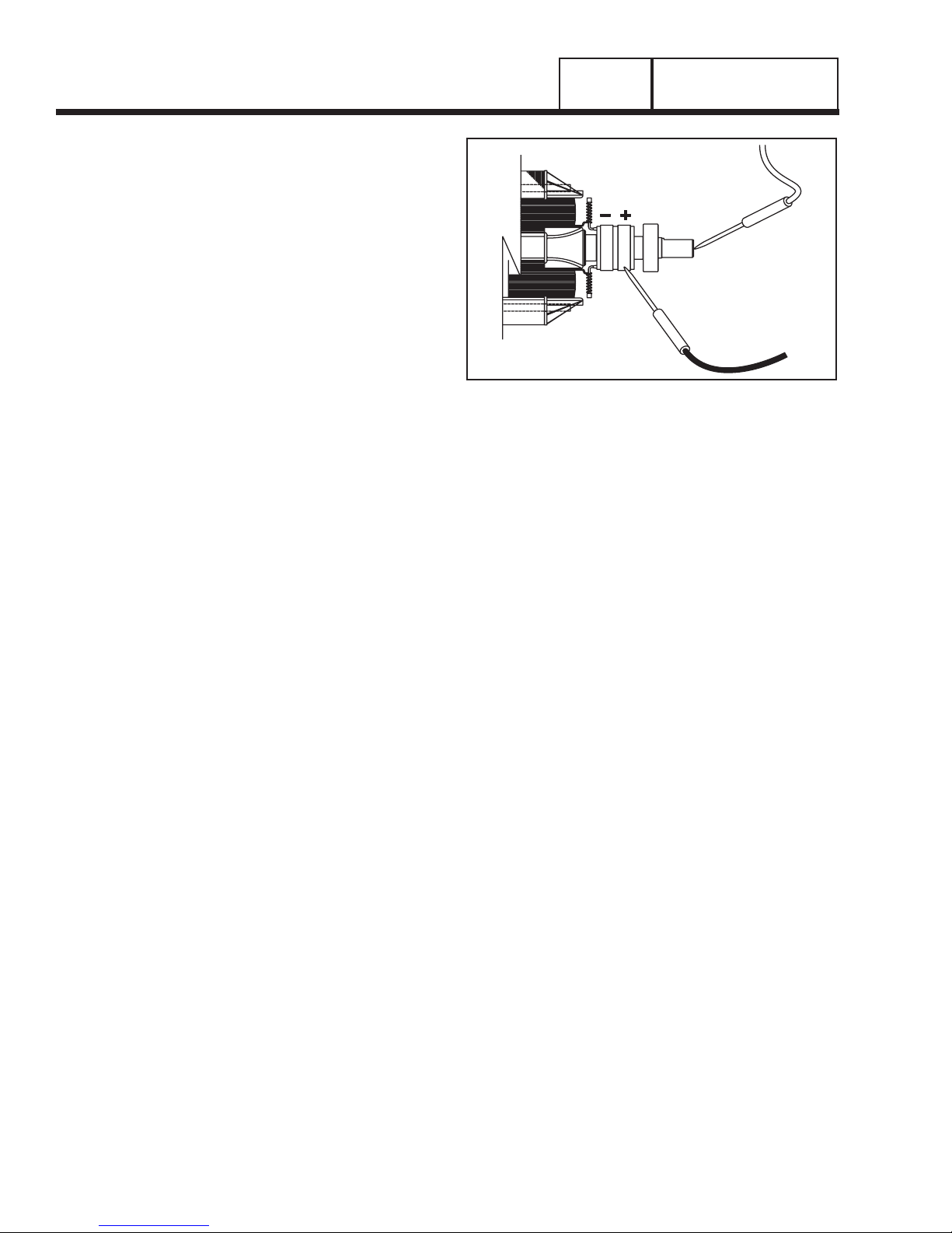
POSITIVE (+)
TEST LEAD
Figure 10. Testing Rotor Insulation
GENERAL INFORMATION
ROTOR INSULATION RESISTANCE TEST
Before attempting to test rotor insulation, the brush
holder must be completely removed. The rotor must
be completely isolated from other components before
starting the test. Attach all leads of all stator windings
to ground.
1. Connect the red tester lead to the positive (+) slip ring
(nearest the rotor bearing).
2. Connect the black tester probe to a clean frame ground,
such as a clean metal part of the rotor shaft.
3. Turn the tester switch OFF.
4. Plug the tester into a 120 volts AC wall socket and set
the voltage switch to “1500 volts”.
5. Turn the tester switch “On” and make sure the pilot light
has turned on.
6. Observe the breakdown lamp, then turn the tester switch
OFF. DO NOT APPLY VOLTAGE LONGER THAN ONE
(1) SECOND.
If the breakdown lamp came on during the one (1)
second test, cleaning and drying of the rotor may be
necessary. After cleaning and drying, repeat the insulation breakdown test. If breakdown lamp comes on
during the second test, replace the rotor assembly.
CLEANING THE GENERATOR
Caked or greasy dirt may be loosened with a soft
brush or a damp cloth. A vacuum system may be
used to clean up loosened dirt. Dust and dirt may
also be removed using dry, low-pressure air (25 psi
maximum).
CAUTION: Do not use sprayed water to clean
the generator. Some of the water will be
retained on generator windings and terminals,
and may cause very serious problems.
DRYING THE GENERATOR
To dry a generator, proceed as follows:
1. Open the generator main circuit breaker. NO
ELECTRICAL LOADS MUST BE APPLIED TO THE
GENERATOR WHILE DRYING.
2. Disconnect all Wires 4 from the voltage regulator.
3. Provide an external source to blow warm, dry air through
the generator interior (around the rotor and stator windings. DO NOT EXCEED 185° F. (85° C.).
4. Start the generator and let it run for 2 or 3 hours.
5. Shut the generator down and repeat the stator and rotor
insulation resistance tests.
Page 22
Page 25
GENERAL INFORMATION
LOW OIL SWITCH HIGH TEMP SWITCH
PART 1
SECTION 1.5
ENGINE-GENERATOR PROTECTIVE DEVICES
GENERAL
Standby electric power generators will often run
unattended for long periods of time. Such operating
parameters as (a) battery voltage, (b) engine oil pressure, (c) engine temperature, (d) engine operating
speed, and (e) engine cranking and startup are not
monitored by an operator during automatic operation.
Because engine operation will not be monitored, the
use of engine protective safety devices is required to
prevent engine damage in the event of a problem.
Prepackaged generator engines mount several engine
protective devices. These devices work in conjunction
with a circuit board, to protect the engine against
such operating faults as (a) low battery, (b) low engine
oil pressure, (c) high temperature, (d) overspeed, and
(e) overcrank. On occurrence of any one or more of
those operating faults, circuit board action will effect
an engine shutdown.
LOW BATTERY
The microprocessor will continually monitor the battery voltage and turn on the Low Battery LED if the
battery voltage falls below 11.0 volts for one (1) minute. No other action is taken on a low battery condition. Low battery voltage is a non-latching alarm
which will automatically clear if the battery voltage
rises above 11.0 volts. Battery voltage is NOT monitored during the crank cycle.
OVERSPEED SHUTDOWN
During engine cranking and operation, the circuit
board receives AC voltage and frequency signals from
the ignition magneto, via Wire 18. Should the speed
exceed approximately 72 Hz (4320 rpm), circuit board
action will de-energize a “run relay” (mounted on the
circuit board). The relay’s contacts will open, to terminate engine ignition and close a fuel shutoff solenoid.
The engine will then shut down. This feature protects
the engine-generator against damaging overspeeds.
NOTE: The circuit board also uses rpm sensing to
terminate engine cranking.
RPM SENSOR FAILURE
During cranking, if the board does not see a valid
RPM signal within three (3) seconds, it will shut down
and latch out on RPM sensor loss.
During running, if the RPM signal is lost for one full
second the board will shut down the engine, wait 15
seconds, then re-crank the engine.
• If an RPM signal is not detected within the first three
(3) seconds of cranking, the control board will shut
the engine down and latch out on RPM sensor loss.
• If the RPM signal is detected the engine will start
and run normally. If the RPM signal is subsequently
lost again, the control board will try one more recrank attempt before latching out and flashing the
overspeed LED.
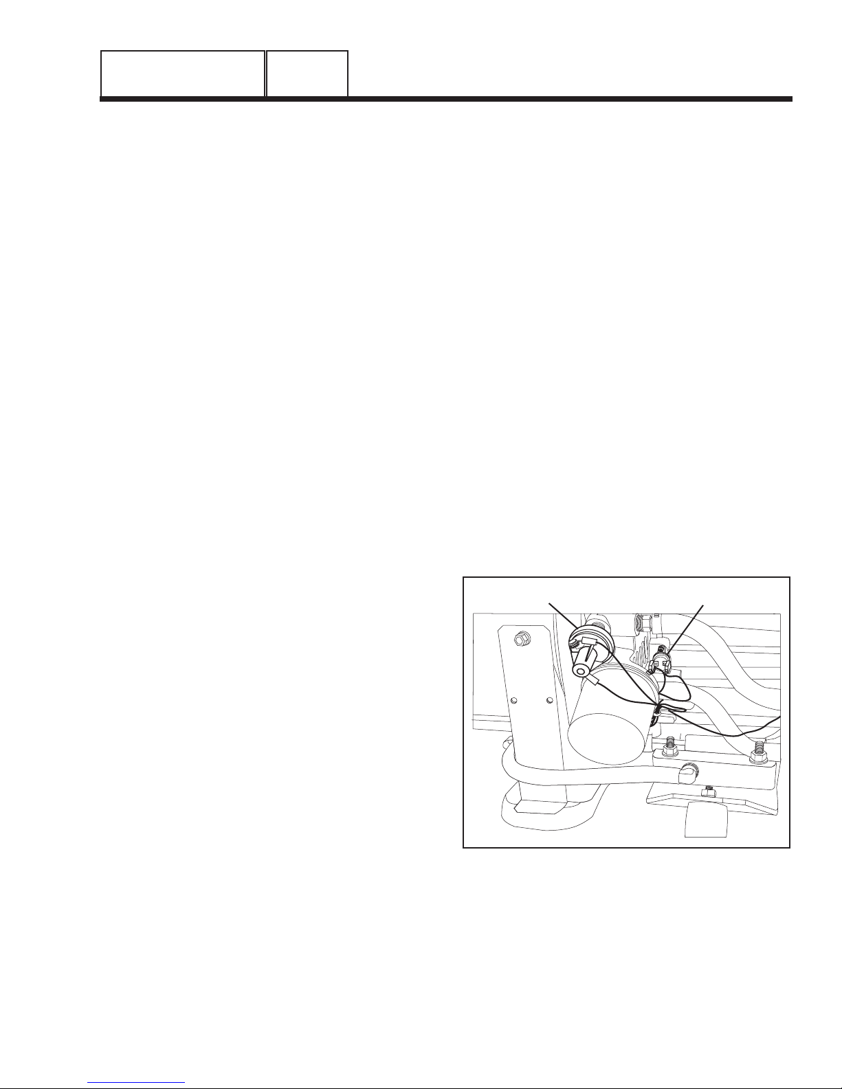
LOW OIL PRESSURE SHUTDOWN
See Figure 1. An oil pressure switch is mounted on
the engine oil filter adapter. This switch has normally
closed contacts that are held open by engine oil pressure during cranking and startup. Should oil pressure
drop below approximately 8 psi, the switch contacts
will close. On closure of the switch contacts, a Wire
86 circuit from the circuit board will be connected to
ground. Circuit board action will then de-energize a
“run relay” (on the circuit board). The run relay’s normally open contacts will then open and a 12 volts DC
power supply to a Wire 14 circuit will then be terminated. This will result in closure of a fuel shutoff solenoid
and loss of engine ignition.
HIGH TEMPERATURE SWITCH
This switch’s contacts (Figure 1) close if the temperature should exceed approximately 140° C (284° F),
initiating an engine shutdown. The generator will automatically restart and the LED on the generator control
panel will reset once the temperature has returned to
a safe operating level.
Figure 1. Engine Protective Switches on an
Air-Cooled Engine
Page 23
Page 26

SECTION 1.5
ENGINE-GENERATOR PROTECTIVE DEVICES
OVERCRANK SHUTDOWN
This feature prevents the generator from damaging
itself when it continually attempts to start and another
problem, such as no fuel supply, prevents it from starting. The unit will crank and rest for a preset time limit.
Then, it will stop cranking, and the LED on the generator control panel will light indicating an overcrank
failure. The AUTO/OFF/MANUAL switch will need to
be set to OFF and then back to AUTO to reset the
generator control board.
NOTE: If the fault is not repaired, the overcrank
feature will continue to activate.
APPROXIMATE CRANK CYCLE TIMES:
7 KW UNITS:
15 seconds ON
7 seconds OFF
7 seconds ON
7 seconds OFF
7 seconds ON
7 seconds OFF
7 seconds ON
7 seconds OFF
7 seconds ON
7 seconds OFF
7 seconds ON
If the unit fails to start, the overcrank alarm LED will
be illuminated.
PART 1
GENERAL INFORMATION
10 KW, 13 KW AND 16 KW UNITS:
16 seconds ON
7 seconds OFF
16 seconds ON
7 seconds OFF
7 seconds ON
7 seconds OFF
7 seconds ON
7 seconds OFF
7 seconds ON
7 seconds OFF
If the unit fails to start, the overcrank alarm LED will
be illuminated.
Page 24
Page 27
GENERAL INFORMATION
PART 1
SECTION 1.6
OPERATING INSTRUCTIONS
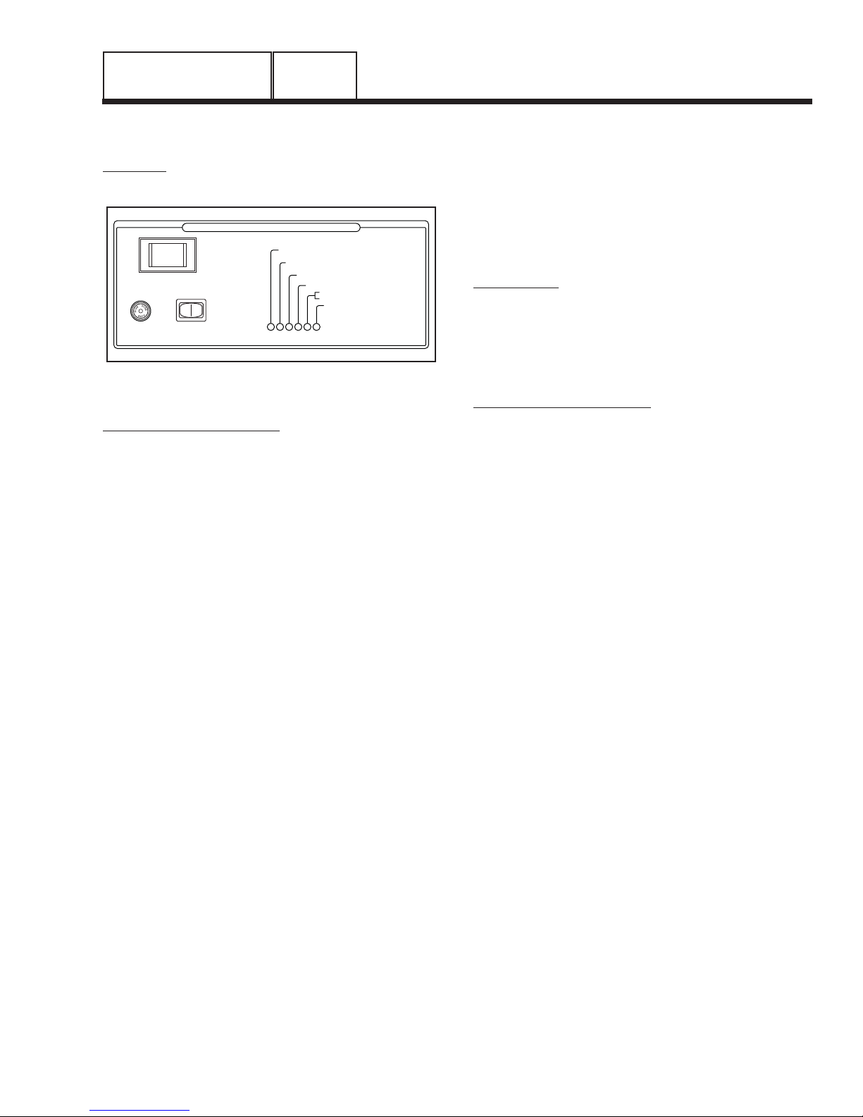
CONTROL PANEL
GENERAL:
See Figure 1 for control panel configurations.
CONTROL AND INFORMATION CENTER
SYSTEM SET
LOW BATTERY
OFF
AUTO. MAN.
SYSTEM FUSE
15A
ASSY: 0F8418/0F8419
SET
EXERCISE
TIME
Figure 1. Control Panel
AUTO-OFF-MANUAL SWITCH:
Use this switch to (a) select fully automatic operation,
(b) to crank and start the engine manually, and (c) to
shut the unit down or to prevent automatic startup.
1. AUTO position:
a.Select AUTO for fully automatic operation.
b.When AUTO is selected, circuit board will moni-
tor utility power source voltage.
c. Should utility voltage drop below a preset level
and remain at such a low level for a preset time,
circuit board action will initiate engine cranking
and startup.
d.Following engine startup, circuit board action
will initiate transfer of electrical loads to the
“Standby” source side.
e.On restoration of utility source voltage above
a preset level, circuit board action will initiate
retransfer back to the “Utility Source” side.
f. Following retransfer, circuit board will shut the
engine down and will then continue to monitor
utility source voltage.
2. OFF Position:
a.Set the switch to OFF to stop an operating
engine.
b.To prevent an automatic startup from occurring,
set the switch to OFF.
3. MANUAL Position:
a.Set switch to MANUAL to crank and start unit
manually.
b.Engine will crank cyclically and start (same as
automatic startup, but without transfer). The unit
will transfer if utility voltage is not available.
DANGER: WHEN THE GENERATOR IS
INSTALLED IN CONJUNCTION WITH AN
AUTOMATIC TRANSFER SWITCH, ENGINE
CRANKING AND STARTUP CAN OCCUR AT
LOW OIL
HIGH TEMP
OVER SPEED
NO RPM SENSE IF FLASHING
OVER CRANK
FLASHING GREEN LED=
NO UTILITY SENSE
5 FLASHING RED LEDS=
EXERCISER NOT SET
ANY TIME WITHOUT WARNING (PROVIDING
THE AUTO-OFF-MANUAL SWITCH IS SET TO
AUTO). TO PREVENT AUTOMATIC STARTUP
AND POSSIBLE INJURY THAT MIGHT BE
CAUSED BY SUCH STARTUP, ALWAYS SET
THE AUTO-OFF-MANUAL SWITCH TO ITS
OFF POSITION BEFORE WORKING ON OR
AROUND THIS EQUIPMENT.
15 AMP FUSE:
This fuse protects the DC control circuit (including the
circuit board) against overload. If the fuse element
has melted open due to an overload, engine cranking
or running will not be possible. Should fuse replacement become necessary, use only an identical 15
amp replacement fuse.
THE SET EXERCISE SWITCH:
This generator is equipped with an exercise timer.
Once it is set, the generator will start and exercise
once every seven days, on the day of the week and at
the time of day the following sequence is completed.
During this exercise period, the unit runs for approximately 12 minutes and then shuts down. Transfer of
loads to the generator output does not occur during
the exercise cycle unless utility power is lost.
A switch on the control panel (see Figure 1) per
mits selection of the day and time for the system to
exercise. At the chosen time, perform the following
sequence to select the desired day and time of day
the system will exercise. Remember seasonal time
changes affect the exercise time settings.
1. Verify that the AUTO/OFF/MANUAL switch is set to
AUTO.
2. Press and hold the "Set Exercise Time" switch for sev-
eral seconds, then release. All the red LED's will flash
for approximately 10 seconds and then stop.
3. Once the red LED's stop flashing, the generator will start
and run for approximately 12 minutes and then shut
down. The exerciser is now set to run at this time of day
each week.
Example: If the "Set Exercise Time" switch is pressed
on Saturday afternoon at 2:00 p.m., the generator will
start and exercise for approximately 12 minutes every
Saturday at 2:00 p.m..
NOTE: The exerciser will only work in the AUTO
mode and will not work unless this procedure
is performed. The exerciser will need to be reset
every time the 12 volt battery is disconnected
and then reconnected, and when the 15A fuse is
removed.
The 16 kW unit has a low speed exercise option. Dip
switch 1 on the control board is factory set to OFF.
This allows the engine to run at a slower speed during
weekly exercise periods for quieter operation. If this
Dip switch is set to ON, the generator will exercise at
it's normal speed.
-
Page 25
Page 28

SECTION 1.6
OPERATING INSTRUCTIONS
PART 1
GENERAL INFORMATION
This DIP switch position is only read at board power
up. If the DIP switch position is changed, power to the
board must be cycled for the micro controller to recognize the new DIP switch position.
Low speed exercise will be handled as follows:
1. The standard start sequence will be initiated.
2. The unit will run at 2,400 RPM.
3. If utility is lost during exercise, the controller will do the
following:
• Wait 10 seconds for utility to return.
• If utility returns within 10 seconds, continue to exer
cise at 2,400 RPM.
• If utility is still lost after 10 seconds, run the engine
up to 3600 RPM and transfer the load. At this time
the controller will exit the exercise routine and
assume full automatic operation.
PROTECTION SYSTEMS:
Unlike an automobile engine, the generator may have
to run for long periods of time with no operator present to monitor engine conditions. For that reason, the
engine is equipped with the following systems that
protect it against potentially damaging conditions:
• Low Battery
• Low Oil Pressure Sensor
• High Temperature Sensor
• Overcrank
• Overspeed
• No RPM Sense
There are LED readouts on the control panel to notify
you that one of these faults has occurred. There is
also a “System Set” LED that is lit when all of the fol
lowing conditions are true:
1. The AUTO-OFF-MANUAL switch is set to the AUTO position.
2. The NOT IN AUTO dip switch is set to the OFF position
on the control board.
3. No alarms are present.
To select automatic operation when a prepackaged
transfer switch is installed along with a prepackaged
home standby generator, proceed as follows:
1. Check that the prepackaged transfer switch main contacts are at their UTILITY position, i.e., the load is
connected to the power supply. If necessary, manually actuate the switch main contacts to their UTILITY
source side. See Part 5 of this manual, as appropriate,
for instructions.
2. Check that utility source voltage is available to transfer
-
switch terminal lugs N1 and N2 (2-pole, 1-phase transfer switches).
3. Set the generator AUTO-OFF-MANUAL switch to its
AUTO position.
4. Actuate the generator main line circuit breaker to its “On”
or “Closed” position. With the preceding Steps 1 through
4 completed, a dropout in utility supply voltage below a
preset level will result in automatic generator cranking
and start-up. Following startup, the prepackaged transfer
switch will be actuated to its “Standby” source side, i.e.,
loads powered by the standby generator.
MANUAL TRANSFER TO “STANDBY” AND
MANUAL STARTUP
To transfer electrical loads to the “Standby” (generator) source and start the generator manually, proceed
as follows:
1. On the generator panel, set the AUTO-OFF-MANUAL
-
switch to OFF.
2. On the generator, set the main line circuit breaker to it’s
OFF or “Open” position.
3. Turn OFF the power supply to the transfer switch, using
whatever means provided (such as a utility source line
circuit breaker).
TO SELECT AUTOMATIC OPERATION
The following procedure applies only to those installations in which the air-cooled, prepackaged automatic
standby generator is installed in conjunction with a
prepackaged transfer switch. Prepackaged transfer
switches do not have an intelligence circuit of their
own. Automatic operation on prepackaged transfer
switch and generator combinations is controlled by
circuit board action.
Page 26
4. Manually actuate the transfer switch main contacts to
their “Standby” position, i.e., loads connected to the
“Standby” power source side.
NOTE: For instructions on manual operation of
prepackaged transfer switches, see Part 5.
5. On the generator panel, set the AUTO-OFF-MANUAL
switch to MANUAL. The engine should crank and start.
6. Let the engine warm up and stabilize for a minute or two
at no-load.
7. Set the generator main line circuit breaker to its “On” or
“Closed” position. The generator now powers the electrical loads.
Page 29

GENERAL INFORMATION
PART 1
MANUAL SHUTDOWN AND RETRANSFER
BACK TO “UTILITY”
To shut the generator down and retransfer electrical
loads back to the UTILITY position, proceed as follows:
1. Set the generator main line circuit breaker to its OFF or
“Open” position.
2. Let the generator run at no-load for a few minutes, to cool.
3. Set the generator AUTO-OFF-MANUAL switch to OFF.
Wait for the engine to come to a complete stop.
4. Turn off the utility power supply to the transfer switch
using whatever means provided (such as a utility source
main line circuit breaker)
5. Manually actuate the prepackaged transfer switch to its
UTILITY source side, i.e., load connected to the utility
source.
6. Turn on the utility power supply to the transfer switch,
using whatever means provided.
SECTION 1.6
OPERATING INSTRUCTIONS
7. Set the generator AUTO-OFF-MANUAL switch to AUTO.
Page 27
Page 30

SECTION 1.7
AUTOMATIC OPERATING PARAMETERS
PART 1
GENERAL INFORMATION
INTRODUCTION
When the prepackaged generator is installed in
conjunction with a prepackaged transfer switch,
either manual or automatic operation is possible.
Manual transfer and engine startup, as well as
manual shutdown and retransfer are covered in
Section 1.6. Selection of fully automatic operation
is also discussed in that section. This section will
provide a step-by-step description of the sequence
of events that will occur during automatic operation
of the system.
AUTOMATIC OPERATING SEQUENCES
The generator’s control panel houses a control logic
circuit board. This board constantly monitors utility power source voltage. Should that voltage drop
below a preset level, circuit board action will signal
the engine to crank and start. After the engine starts,
the circuit board signals the transfer switch to activate
and connect load circuits to the standby power supply
(load terminal lugs T1/T2 connect to terminal lugs E1/
E2). Refer to the Electrical Data section.
The generator must run at 50 Hz or greater for the
transfer output to be activated. Once activated, it will
remain active even if the frequency dips below 50 Hz.
Upon restoration of utility source voltage above a
preset level, generator circuit board action signals the
transfer switch to transfer loads back to that power
supply. After retransfer, the engine is signalled to shut
down.
The actual sequence of operation is controlled by
sensors and timers on a control logic circuit board, as
follows:
A. Utility Voltage Dropout Sensor
• This sensor monitors utility source voltage.
• If utility source voltage drops below about 65 percent
of the nominal supply voltage, the sensor energizes a
10 second timer.
• Once the timer has expired, the engine will crank and
start if utility is still low.
B. Engine Warm-up Time Delay
• This mechanism lets the engine warm up for about
five (5) seconds before the load is transferred to the
standby source.
C. Standby Voltage Sensor
• This sensor monitors generator AC output voltage.
When the voltage has reached 50 percent of the
nominal rated voltage, transfer to standby can occur.
D. Utility Voltage Pickup Sensor
• This sensor monitors utility power supply voltage.
When that voltage is restored above 75 percent of the
nominal source voltage, a retransfer time delay starts
timing.
E. Retransfer Time Delay
• This timer runs for about 15 seconds.
• At end of a 15-second delay, circuit board action deenergizes transfer relay in the transfer switch if utility
is still present.
• Retransfer to utility power source then occurs.
F. Engine Cool-down Timer
Page 28
• When the load is transferred back to utility power
source, the engine cool-down timer starts timing.
• The timer will run for about one minute, and the gen
erator will then shut down.
-
Page 31

PART 2
AC GENERATORS
Air-cooled, Prepackaged
Automatic Standby
Generators
TABLE OF CONTENTS
PART TITLE PAGE#
2.1. Description and Components 30
2.2 Operational Analysis 33
2.3 Troubleshooting Flow Charts 35
2.4 Diagnostic Tests 39
2.1 Description and Components
Introduction ......................................................30
Engine-generator Drive System .......................30
The AC Generator ............................................30
Rotor Assembly ................................................30
Stator Assembly ...............................................31
Brush Holder And Brushes ..............................31
Other AC Generator Components ...................31
2.2 Operational Analysis ....................................... 33
Rotor Residual Magnetism...............................33
Field Boost .......................................................33
Operation .........................................................34
2.3 Troubleshooting Flowcharts ............................. 35
Problem 1 - Generator Produces Zero
Voltage or Residual Voltage .......... 35-36
Problem 2 - Generator Produces
Low Voltage at No-Load ......................37
Problem 3 - Generator Produces
High Voltage at No-Load .....................37
Problem 4 - Voltage and Frequency Drop
Excessively When Loads are Applied .38
2.3 Diagnostic Tests .............................................. 39
Introduction ......................................................39
Safety ............................................................39
.......................... 30
Test 1 - Check Main Circuit Breaker.................39
Test 2 - Check AC Output Voltage ....................39
Test 4 - Fixed Excitation Test/Rotor
Amp Draw Test ....................................40
Test 5 - Wire Continuity ....................................41
Test 6 - Check Field Boost ...............................42
Test 7 - Testing The Stator With a VOM ...........42
Test 8 - Resistance Check of Rotor Circuit ......44
Test 9 - Check Brushes and Slip Rings ............44
Test 10 - Test Rotor Assembly .........................45
Test 11 - Check AC Output Frequency.............45
Test 12 - Check And Adjust Engine Governor
(Single Cylinder Units) .........................46
Test 12A - Check Stepper Motor Control
(V-twin Engine Units) ...........................46
Test 13 - Check And Adjust
Voltage Regulator ................................48
Test 14 - Check Voltage And
Frequency Under Load ........................48
Test 15 - Check For Overload Condition ..........48
Test 16 - Check Engine Condition ....................48
Page 29
Page 32

SECTION 2.1
DESCRIPTION & COMPONENTS
PART 2
AC GENERATORS
INTRODUCTION
The air-cooled, pre-packaged automatic standby system is an easy to install, fully enclosed and self-sufficient electric power system. It is designed especially
for homeowners, but may be used in other applications as well. On occurrence of a utility power failure,
this high performance system will (a) crank and start
automatically, and (b) automatically transfer electrical
loads to generator AC output.
The generator revolving field (rotor) is driven by an
air-cooled engine at about 3600 rpm.
The generator may be used to supply electrical power
for the operation of 120 and/or 240 volts, 1-phase, 60
Hz, AC loads.
A 2-pole, “V-Type”, prepackaged transfer switch is
shipped with the unit (see Part 3). Prepackaged trans
fer switches do not include an “intelligence circuit” of
their own. Instead, automatic startup, transfer, running, retransfer and shutdown operations are controlled by a solid state circuit board in the generator
control panel.
ENGINE-GENERATOR DRIVE SYSTEM
The generator revolving field is driven by an aircooled, horizontal crankshaft engine. The generator is
directly coupled to the engine crankshaft (see Figure
1), and mounted in an enclosure. Both the engine and
generator rotor are driven at approximately 3600 rpm,
to provide a 60 Hz AC output.
THE AC GENERATOR
Figure 1 shows the major components of the AC generator.
ROTOR ASSEMBLY
The 2-pole rotor must be operated at 3600 rpm to
supply a 60 Hertz AC frequency. The term “2-pole”
means the rotor has a single north magnetic pole and
a single south magnetic pole. As the rotor rotates, its
lines of magnetic flux cut across the stator assem-
bly windings and a voltage is induced into the stator
windings. The rotor shaft mounts a positive (+) and
a negative (-) slip ring, with the positive (+) slip ring
nearest the rear bearing carrier. The rotor bearing is
pressed onto the end of the rotor shaft. The tapered
rotor shaft is mounted to a tapered crankshaft and is
held in place with a single through bolt.
BRUSH HOLDER
ASSEMBLY
ROTOR
S TATO R
ENGINE
ENGINE
ADAPTOR
REAR BEARING
CARRIER
Figure 1. AC Generator Exploded View
Page 30
Page 33

AC GENERATORS
PART 2
SECTION 2.1
DESCRIPTION & COMPONENTS
Wire 4 connects to the positive (+) brush and Wire 0
to the negative (-) brush. Wire 0 connects to frame
ground. Rectified and regulated excitation current, as
well as current from a field boost circuit, are delivered
to the rotor windings via Wire 4, and the positive (+)
brush and slip ring. The excitation and field boost current passes through the windings and to frame ground
via the negative (-) slip ring and brush, and Wire 0.
This current flow creates a magnetic field around the
rotor having a flux concentration that is proportional to
the amount of current flow.
Figure 2. The 2-Pole Rotor Assembly
STATOR ASSEMBLY
The stator can houses and retains (a) dual AC power
windings, (b) excitation winding, and (c) battery
charge winding. A total of ten (10) stator leads are
brought out of the stator can as shown in Figure 3.
The stator can is sandwiched between an engine
adapter and a rear bearing carrier. It is retained in that
position by four stator studs.
2
6
11P
11S
22P
22S
33
44
66
77
Figure 3 Stator Assembly Leads
BRUSH HOLDER AND BRUSHES
The brush holder is retained to the rear bearing carrier by means of two #10-32 x 9/16 Taptite screws. A
positive (+) and a negative (-) brush are retained in
the brush holder, with the positive (+) brush riding on
the slip ring nearest the rotor bearing.
0
-
+
Figure 4. Brush Holder and Brushes
4
OTHER AC GENERATOR COMPONENTS
Some AC generator components are housed in the
generator control panel enclosure, and are not shown
in Figure 1. These are (a) a voltage regulator, and (b)
a main line circuit breaker.
VOLTAGE REGULATOR:
A typical voltage regulator is shown in Figure 5.
Unregulated AC output from the stator excitation
winding is delivered to the regulator’s DPE terminals,
via Wire 2 and Wire 6. The voltage regulator rectifies
that current and, based on stator AC power winding
sensing, regulates it. The rectified and regulated excitation current is then delivered to the rotor windings
from the positive (+) and negative (-) regulator terminals, via Wire 4 and Wire 0. Stator AC power winding
“sensing” is delivered to the regulator “SEN” terminals
via Wires 11 and 22.
The regulator provides “over-voltage” protection, but
does not protect against “under-voltage”. On occur
rence of an “over-voltage” condition, the regulator will
“shut down” and complete loss Of excitation current
to the rotor will occur. Without excitation current, the
generator AC output voltage will drop to approximately
one-half (or lower) of the unit’s rated voltage.
-
Page 31
Page 34

SECTION 2.1
DESCRIPTION & COMPONENTS
Figure 5. Typical Voltage Regulator
PART 2
AC GENERATORS
A single red lamp (LED) glows during normal opera
tion. The lamp will become dim if excitation winding
AC output diminishes. It will go out on occurrence of
an open condition in the sensing AC output circuit.
An adjustment potentiometer permits the stator AC
power winding voltage to be adjusted. Perform this
adjustment with the generator running at no-load, and
with a frequency of:
• 57.5-59.5 Hz (V-Twins units)
• 62-63 Hz (Single Cylinder units)
At the stated no-load frequency, adjust to obtain a
line-to-line AC voltage of:
• 250-252 volts (V-Twins units)
• 247-252 volts (Single Cylinder units)
MAIN LINE CIRCUIT BREAKER:
The main line circuit breaker protects the generator
against electrical overload. See “Specifications” in
front of manual for amp ratings.
-
Page 32
Page 35

AC GENERATORS
PART 2
SECTION 2.2
OPERATIONAL ANALYSIS
ROTOR RESIDUAL MAGNETISM
The generator revolving field (rotor) may be considered to be a permanent magnet. Some “residual”
magnetism is always present in the rotor. This residual magnetism is sufficient to induce a voltage into the
stator AC power windings that is approximately 2-12
volts AC.
FIELD BOOST
FIELD BOOST CIRCUIT:
When the engine is cranking, direct current flow is
delivered from a circuit board to the generator rotor
windings, via Wire 4.
The field boost system is shown schematically in
Figure 2. Manual and automatic engine cranking
is initiated by circuit board action, when that circuit
board energizes a crank relay. Battery voltage is then
delivered to field boost Wire 4 (and to the rotor), via
a field boost resistor and diode. The crank relay, field
boost resistor and diode are all located on the circuit
board.
Notice that field boost current is available only while
the crank relay is energized, i.e., while the engine is
cranking.
Field boost voltage is reduced from that of battery
voltage by the resistor action and, when read with a
DC voltmeter, will be approximately 9 or 10 volts DC.
+12 VDC
13
56
4
FIELD
BOOST
TO
ROTOR
TO
STARTER
STARTER
CONTACTOR
DIODE
BASE
TRANSISTOR
RESISTOR
CRANK
RELAY K1
CIRCUIT BOARD
FIELD
BOOST
DIODE
FIELD
BOOST
PIN 5
PIN 1
Figure 2. Field Boost Circuit Schematic
Figure 1. Operating Diagram of AC Generator
Page 33
Page 36

SECTION 2.2
OPERATIONAL ANALYSIS
PART 2
AC GENERATORS
OPERATION
STARTUP:
When the engine is started, residual plus field boost
magnetism from the rotor induces a voltage into (a)
the stator AC power windings, (b) the stator excitation or DPE windings, and (c) the stator battery
charge winding. In an “on-speed” condition, residual
plus field boost magnetism are capable of creating
approximately one-half the unit’s rated voltage.
ON-SPEED OPERATION:
As the engine accelerates, the voltage that is induced
into the stator windings increases rapidly, due to the
increasing speed at which the rotor operates.
FIELD EXCITATION:
An AC voltage is induced into the stator excitation
(DPE) windings. The DPE winding circuit is completed to the voltage regulator, via Wire 2 and Wire
6. Unregulated alternating current can flow from the
winding to the regulator.
The voltage regulator “senses” AC power winding out
put voltage and frequency via stator Wires 11 and 22.
The regulator changes the AC from the excitation
winding to DC. In addition, based on the Wires 11 and
22 sensing signals, it regulates the flow of direct current to the rotor.
The rectified and regulated current flow from the regu
lator is delivered to the rotor windings, via Wire 4, and
the positive brush and slip ring. This excitation current
flows through the rotor windings and is directed to
ground through the negative (-) slip ring and brush,
and Wire 0.
The greater the current flow through the rotor windings, the more concentrated the lines of flux around
the rotor become.
The more concentrated the lines of flux around the
rotor that cut across the stationary stator windings,
the greater the voltage that is induced into the stator
windings.
Initially, the AC power winding voltage sensed by the
regulator is low. The regulator reacts by increasing
the flow of excitation current to the rotor until volt
age increases to a desired level. The regulator then
maintains the desired voltage. For example, if voltage
exceeds the desired level, the regulator will decrease
the flow of excitation current. Conversely, if voltage
drops below the desired level, the regulator responds
by increasing the flow of excitation current.
AC POWER WINDING OUTPUT:
A regulated voltage is induced into the stator AC
power windings. When electrical loads are connected
across the AC power windings to complete the circuit, current can flow in the circuit. The regulated AC
power winding output voltage will be in direct proportion to the AC frequency. For example, on units rated
120/240 volts at 60 Hz, the regulator will try to main-
tain 240 volts (line-to-line) at 60 Hz. This type of regulation system provides greatly improved motor starting
capability over other types of systems.
BATTERY CHARGE WINDING OUTPUT:
A voltage is induced into the battery charge windings.
Output from these windings is delivered to a battery
charger, via Wires 66 and 77. The resulting direct current from the battery charger is delivered to the unit
battery, via Wire 13. This output is used to maintain
battery state of charge during operation.
-
Page 34
Page 37

AC GENERATORS
PART 2
GENERAL
Use the “Flow Charts” in conjunction with the detailed
instructions in Section 2.4. Test numbers used in
the flow charts correspond to the numbered tests in
Section 2.4.
Problem 1 - Generator Produces Zero Voltage or Residual Voltage
TEST 1 - CHECK
MAIN CIRCUIT
BREAKER
RESET TO
“ON”
OR REPLACE
IF BAD
TEST 4 - PERFORM
FIXED EXCITATION /
A
ROTOR AMP DRAW
D
B
C
SECTION 2.3
TROUBLESHOOTING FLOWCHARTS
The first step in using the flow charts is to correctly
identify the problem. Once that has been done, locate
the problem on the following pages. For best results,
perform all tests in the exact sequence shown in the
flow charts.
RE-TEST
G
REPAIR
OR REPLACE
FUSES
CHECK
FUSES
VOM
TEST 5 - WIRE
CONTINUITY
GOOD
TEST 6 -
FIELD BOOST
BAD
GOOD
REPLACE
VO LTAG E
REGULATOR
BAD
REPAIR
OR
REPLACE
THEN
RETEST
TEST 7 - TEST
S TATO R
BAD
REPAIR
OR
REPLACE
GOOD
PERFORM STATOR
INSULATION
RESISTANCE TEST
-
SECTION 1.4
BAD
TEST 8 -
CIRCUIT
REPAIR
OR
REPLACE
CHECK
ROTOR
BAD
BAD
BAD
GOOD
BAD
TEST 9 -
CHECK
BRUSHES &
SLIP RINGS
GOOD
TEST 10 -
TEST ROTOR
ASSEMBLY
GOOD
PERFORM ROTOR
INSULATION
RESISTANCE TEST
-
SECTION 1.4
Page 35
Page 38

SECTION 2.3
TROUBLESHOOTING FLOWCHARTS
Problem 1 - Generator Produces Zero Voltage or Residual Voltage
(Continued)
PART 2
AC GENERATORS
TEST 10 -
TEST ROTOR
ASSEMBLY
GOOD
PERFORM ROTOR
INSULATION
RESISTANCE TEST -
SECTION 1.4
GOOD
TEST 7 - TEST
S TATO R
TEST 4 - PERFORM
FIXED EXCITATION /
E
ROTOR AMP DRAW
BAD
BAD
BAD
H
REPAIR
OR
REPLACE
F
TEST 7 - TEST
S TATO R
GOOD
PERFORM STATOR
INSULATION
RESISTANCE TEST -
SECTION 1.4
GOOD
TEST 10 -
TEST ROTOR
ASSEMBLY
GOOD
BAD
BAD
REPAIR
OR
REPLACE
BAD
GOOD
PERFORM STATOR
INSULATION
RESISTANCE TEST -
SECTION 1.4
GOOD
RE-TEST
TEST 4
BAD
PERFORM ROTOR
INSULATION
RESISTANCE TEST -
SECTION 1.4
GOOD
RE-TEST
TEST 4
BAD
Page 36
Page 39

AC GENERATORS
PART 2
TROUBLESHOOTING FLOWCHARTS
Problem 2 - Generator Produces Low Voltage at No-Load
SECTION 2.3
TEST 2 - CHECK
AC OUTPUT
VOLTAGE
TEST 13- ADJUST
VO LTAG E
REGULATOR
FREQUENCY O.K.,
BUT VOLTAGE IS
STILL LOW
LOW
TEST 11 - CHECK
AC OUTPUT
FREQUENCY
FREQUENCY O.K.,
BUT VOLTAGE LOW
VOLTAGE AND FREQUENCY O.K.
GO TO “PROBLEM 1”
FLOW CHART - START
AT “TEST 4 - F/E”
LOW -
SINGLE CYLINDER
UNITS
LOW -
V-TWIN UNITS
TEST 12 - ADJUST
ENGINE GOVERNOR
TEST 12A - CHECK
STEPPER MOTOR
CONTROL
Problem 3 - Generator Produces High Voltage at No-Load
FREQUENCY AND
VOLTAGE O.K.
STOP
TESTS
TEST 2 - CHECK
AC OUTPUT
VOLTAGE
TEST 13- ADJUST
VO LTAG E
REGULATOR
FREQUENCY O.K.,
BUT VOLTAGE IS
STILL HIGH
HIGH
TEST 11 - CHECK
AC OUTPUT
FREQUENCY
FREQUENCY O.K.,
BUT VOLTAGE HIGH
VOLTAGE AND FREQUENCY O.K.
REPLACE DEFECTIVE
VOLTAGE REGULATOR
HIGH -
SINGLE CYLINDER
UNITS
HIGH -
V-TWIN UNITS
TEST 12 - ADJUST
ENGINE GOVERNOR
TEST 12A - CHECK
STEPPER MOTOR
CONTROL
FREQUENCY AND
VOLTAGE O.K.
STOP
TESTS
Page 37
Page 40

SECTION 2.3
PART 2
TROUBLESHOOTING FLOWCHARTS
Problem 4 - Voltage and Frequency Drop Excessively When Loads Are Applied
AC GENERATORS
TEST 14 - CHECK
VOLTAGE AND
FREQUENCY
UNDER LOAD
GOOD
DISCONTINUE
TESTING
TEST 80 - CHECK
LC1 & LC2 WIRING
REPAIR OR REPLACE
DEFECTIVE WIRING
BOTH
LOW
TEST 15 - CHECK
FOR OVERLAOD
CONDITION
OVERLOADED
REDUCE LOADS TO UNIT’S
RATED CAPACITY
TEST 81 - CHECK
IDLE CONTROL
TRANSFORMER
PRIMARY WIRING
BAD BADBAD
REPAIR OR REPLACE
DEFECTIVE WIRING
NOT
OVERLOADED
GOODGOOD
IF RECONFIGURED TO LP GAS,
VERIFY THAT PROPER
PROCEDURE WAS FOLLOWED
(REFER TO SECTION 1.3)
UNITS WITH
V-TWIN
ENGINES
TEST 79 - CHECK
IDLE CONTROL
TRANSFORMER
REPAIR OR REPLACE
THE IDLE CONTROL
TRANSFORMER
UNITS WITH
SINGLE
CYLINDER
ENGINES
LOOK FOR A SHORTED
CONDITION IN A
CONNECTED LOAD OR
IN ONE OF THE LOAD
CIRCUITS
REPAIR OR REPLACE
GOOD
GOOD
TEST 12A - CHECK
REPAIR OR REPLACE
TEST 7 - CHECK
S TATO R A C
POWER WINDINGS
BAD
STEPPER MOTOR
CONTROL
BAD
ENGINE
CONDITION
GOOD
GOOD
TEST 12 - CHECK AND
ADJUST ENGINE
GOVERNOR
GOOD
GO TO “PROBLEM 11 - ENGINE
STARTS HARD AND RUNS
ROUGH/LACKS POWER”
SECTION 4.3
Page 38
Page 41

AC GENERATORS
OFF
WIRE 11
TERMINAL
E1 TERMINAL
E2 TERMINAL
WIRE 44
TERMINAL
PART 2
SECTION 2.4
DIAGNOSTIC TESTS
INTRODUCTION
This section is provided to familiarize the service
technician with acceptable procedures for the testing and evaluation of various problems that could be
encountered on prepackaged standby generators with
air-cooled engine. Use this section of the manual in
conjunction with Section 2.3, “Troubleshooting Flow
Charts”. The numbered tests in this section correspond with those of Section 2.3.
Test procedures in this section do not require the use
of specialized test equipment, meters or tools. Most
tests can be performed with an inexpensive voltohm-milliammeter (VOM). An AC frequency meter is
required, where frequency readings must be taken. A
clamp-on ammeter may be used to measure AC loads
on the generator.
Testing and troubleshooting methods covered in this
section are not exhaustive. We have not attempted
to discuss, evaluate and advise the home stand
by service trade of all conceivable ways in which
service and trouble diagnosis might be performed.
We have not undertaken any such broad evaluation.
Accordingly, anyone who uses a test method not recommended herein must first satisfy himself that the
procedure or method he has selected will jeopardize
neither his nor the product’s safety.
1. Set a volt-ohm-milliammeter (VOM) to its “R x 1” scale
and zero the meter.
2. With the generator shut down, disconnect all wires from
the main circuit breaker terminals, to prevent interaction.
3. With the generator shut down, connect one VOM test
probe to the Wire 11 terminal of the breaker and the
other test probe to the Wire E1 terminal.
4. Set the breaker to its “On” or “Closed” position. The VOM
should read CONTINUITY.
5. Set the breaker to its OFF or “Open” position and the
VOMshould indicate
INFINITY.
6. Repeat Steps 4 and 5 with the VOM test probes connected across the breaker’s Wire 44 terminal and the E2
terminal.
RESULTS:
1. If the circuit breaker tests good, go on to Test 2.
2. If the breaker tests bad, it should be replaced.
SAFETY
Service personnel who work on this equipment must
be made aware of the dangers of such equipment.
Extremely high and dangerous voltages are present
that can kill or cause serious injury. Gaseous fuels are
highly explosive and can be ignited by the slightest
spark. Engine exhaust gases contain deadly carbon
monoxide gas that can cause unconsciousness or
even death. Contact with moving parts can cause serious injury. The list of hazards is seemingly endless.
When working on this equipment, use common
sense and remain alert at all times. Never work on
this equipment while you are physically or mentally
fatigued. If you don’t understand a component, device
or system, do not work on it.
TEST 1- CHECK MAIN CIRCUIT BREAKER
DISCUSSION:
Often the most obvious cause of a problem is over-
looked. If the generator main line circuit breaker is set
to OFF or “Open”, no electrical power will be supplied
to electrical loads. If loads are not receiving power,
perhaps the main circuit breaker is open or has failed.
PROCEDURE:
The generator main circuit breaker is located on the
control panel. If loads are not receiving power, make
sure the breaker is set to “On” or “Closed”.
If you suspect the breaker may have failed, it can be
tested as follows (see Figure 1):
Figure 1. Generator Main Circuit Breaker Test Points
TEST 2- CHECK AC OUTPUT VOLTAGE
DISCUSSION:
A volt-ohm-milliammeter (VOM) may be used to check
the generator output voltage. Output voltage may be
checked at the unit’s main circuit breaker terminals.
Refer to the unit’s DATA PLATE for rated line-to-line
and line-to-neutral voltages.
Page 39
Page 42

SECTION 2.4
DIAGNOSTIC TESTS
PART 2
AC GENERATORS
DANGER: USE EXTREME CAUTION
PROCEDURE:
DURING THIS TEST. THE GENERATOR WILL
BE RUNNING. HIGH AND DANGEROUS
VOLTAGES WILL BE PRESENT AT THE
TEST TERMINALS. CONNECT METER TEST
CLAMPS TO THE HIGH VOLTAGE TERMINALS
WHILE THE GENERATOR IS SHUT DOWN.
STAY CLEAR OF POWER TERMINALS
DURING THE TEST. MAKE SURE METER
CLAMPS ARE SECURELY ATTACHED AND
WILL NOT SHAKE LOOSE.
1. With the engine shut down, connect the AC voltmeter
test leads across the Wires 11 and 44 terminals of the
generator main circuit breaker (see Figure 1). These
connections will permit line-to-line voltages to be read.
2. Set the generator main circuit breaker to its OFF or
“Open” position. This test will be conducted with the
generator running at no-load.
3. Start the generator, let it stabilize and warm up for a
minute or two.
ning, this should create a proportional voltage output
from the stator windings.
PROCEDURE:
1. Disconnect Wire 4 from the voltage regulator, 3rd terminal from the top. See Figure 2.
2. Connect a jumper wire to the disconnected Wire 4 and
to the 12 volt fused battery supply Wire 15 (located at
15A fuse).
3. Set VOM to AC volts.
4
0
6
2
4
22
11
4. Take the meter reading. On unit’s having a rated line-toline voltage of 240 volts, the no-load voltage should be
about 242-252 volts AC.
5. Shut the engine down and remove the meter test leads.
RESULTS:
1. If zero volts or residual voltage is indicated, go on to
Test 4.
2. If the voltage reading is higher than residual, but is lower
than the stated limits, go to Test 11.
3. If a high voltage is indicated, go on to Test 11.
NOTE: “Residual” voltage may be defined as the
voltage that is produced by rotor residual magnetism alone. The amount of voltage induced into
the stator AC power windings by residual voltage alone will be approximately 2 to 16 volts AC,
depending on the characteristics of the specific
generator. If a unit is supplying residual voltage
only, either excitation current is not reaching the
rotor or the rotor windings are open and the excitation current cannot pass. On current units with
air-cooled engine, “field boost” current flow is
available to the rotor only during engine cranking.
TEST 4- FIXED EXCITATION TEST
/ROTOR AMP DRAW TEST
Figure 2. Voltage Regulator
4. Disconnect Wire 2 from the voltage regulator and connect one meter test lead to that wire. Disconnect Wire
6 from the voltage regulator and connect the other
meter test lead to that wire. Wires 2 and 6 are located
at the bottom two terminals of the voltage regulator (see
Figure 2).
5. Set the AUTO-OFF-MANUAL switch to MANUAL. Once
the engine starts, record the AC voltage.
6. Set the AUTO-OFF-MANUAL switch to OFF. Reconnect
Wire 2 and Wire 6.
7. Disconnect Wire 11 from the voltage regulator and connect one meter test lead to that wire. Disconnect Wire
22 from the voltage regulator and connect the other
meter test lead to that wire (both wires are located at the
top two terminals of the voltage regulator, see Figure 2).
8. Set the AUTO-OFF-MANUAL switch to MANUAL. Once
the engine starts, record the AC voltage.
9. Set the AUTO-OFF-MANUAL switch to OFF. Reconnect
Wire 11 and Wire 22.
10.Set VOM to DC amperage.
DISCUSSION:
Supplying a fixed DC current to the rotor will induce
a magnetic field in the rotor. With the generator run-
Page 40
11.Remove jumper lead connected to Wire 4 and Wire 15.
12.Connect one meter test lead to battery positive twelvevolt supply Wire 15, located at the 15A fuse. Connect
Page 43

AC GENERATORS
PART 2
the other meter test lead to Wire 4 (still disconnected
from previous tests). Measure and record static rotor
amp draw.
13.Set the AUTO-OFF-MANUAL switch to the MANUAL
position. Once the engine starts, repeat Step 12.
Measure and record running rotor amp draw with the
engine running.
14.Set the AUTO-OFF-MANUAL switch to OFF. Reconnect
Wire 4 to the voltage regulator.
RESULTS:
Refer to the chart on this page: “Results - Fixed
Excitation Test/Rotor Amp Draw Test”.
SECTION 2.4
DIAGNOSTIC TESTS
0.91-1.06A
0.91-1.06A
0.91-1.06A
0.91-1.06A
Above 1.5A
Zero
Draw
Current
Zero
Current
Draw
Î
EXAMPLE:
MODEL 5240
WIRE2&6VOLTAGE 87VAC
WIRE 11 & 22 VOLTAGE 31 VAC
STATIC ROTOR AMP DRAW 1.0 AMP
RUNNING ROTOR AMP DRAW 1.0 AMP
These results match Column B in the chart. Refer
back to Problem 1 Flow Chart and follow Letter B.
TEST 5: WIRE CONTINUITY
DISCUSSION:
The voltage regulator receives unregulated alternating
current from the stator excitation winding, via Wires 2
and 6. It also receives voltage sensing from the stator AC power windings, via Wires 11 and 22. The
regulator rectifies the AC from the excitation winding
and based on the sensing signals, regulates the DC
current flow to the rotor. The rectified and regulated
current flow is delivered to the rotor brushes via Wires
4 (positive) and 0 (negative). This test will verify the
integrity of Wire 0.
Below 60 VAC Below 60 VAC Above 60 VAC Below 60 VAC
Volts
Zero or Residual
Below 60 VAC Below 60 VAC Above 60 VAC Below 60 VAC
Volts
Zero or Residual
0.91-1.06A
0.91-1.06A
Above 1.5A
Above 1.5A
Zero
Current
0.91-1.06A
0.91-1.06A
0.91-1.06A
0.91-1.06A
0.91-1.06A
0.91-1.06A
Above 1.5A
Above 1.1A
Draw
0.91-1.06A
0.91-1.06A
0.91-1.06A
0.91-1.06A
Above 1.5A 0.91-1.06A
Zero
Draw
Current
PROCEDURE:
1. Set VOM to its “R x 1” scale.
2. Remove Wire 0 from the voltage regulator, 4th terminal
from the top. Also voltage regulator is labeled (-) next to
terminal.
3. Connect one test lead to Wire 0, connect the other test
lead to a clean frame ground. The meter should read
CONTINUITY.
RESULTS:
If CONTINUITY was not measured, repair or replace
the wire as needed.
TEST 4 RESULTS - FIXED EXCITATION TEST/ROTOR AMP DRAWTEST
ALL Above 60 VAC Above 60 VAC Below 60 VAC
Results: (Model #) ABCDEFGH
Voltage Results
Wire2&6
ALL Above 60 VAC Below 60 VAC Above 60 VAC
Voltage Results
Wire 11 & 22
1.06A
0.91-1.06A
005240, 005280
005241, 005282
005242, 005282
Static Rotor
Amp Draw
1.0A
0.57A
005243, 005283
005244, 005284
ALL 0.91-1.06A 0.91-1.06A 0.91-1.06A
Running Rotor
Amp Draw
Page 41
MATCH RESULTS WITH LETTER AND REFER TO FLOW CHART IN SECTION 2.3 “Problem 1”
Í
Page 44

SECTION 2.4
DIAGNOSTIC TESTS
PART 2
AC GENERATORS
TEST 6 - CHECK FIELD BOOST
DISCUSSION:
See “Field Boost Circuit” in Section 2.2. Field boost
current (from the circuit board) is available to the rotor
only while the engine is cranking. Loss of field boost
output to the rotor may or may not affect power winding AC output voltage. The following facts apply:
• A small amount of voltage must be induced into the
DPE winding to turn the voltage regulator on.
• If rotor residual magnetism is sufficient to induce
a voltage into the DPE winding that is high
enough to turn the voltage regulator on, regulator excitation current will be supplied even if field
boost has failed. Normal AC output voltage will
then be supplied.
• If rotor residual magnetism has been lost or is not
sufficient to turn the regulator on, and field boost
has also been lost, excitation current will not be
supplied to the rotor. Generator AC output voltage
will then drop to zero or nearly zero.
PROCEDURE:
1. Disconnect Wire 4 from the voltage regulator, third termi-
nal from the top (see Figure 4).
2. Set a VOM to read DC volts.
RESULTS:
1. If normal field boost voltage is indicated in Step 6,
replace the voltage regulator.
2. If normal field boost voltage is NOT indicated in Step 6,
check Wire 4 (between regulator and circuit board) for
open or shorted condition. If wire is good, replace the
circuit board.
3. Disconnect C2 Connector from the control panel (see
Figure 3).
4. Connect the positive (+) VOM test probe to the terminal
end of disconnected Wire 4.
5. Connect the common (-) VOM test probe to the
grounding lug.
6. Crank the engine while observing the VOM reading.
While the engine is cranking, the VOM should read
approximately 9-10 volts DC. When engine is not cranking, VOM should indicate “zero” volts (see Figure 4).
7. Reconnect the C2 Connector and Wire 4.
BACK PANEL
C1 CONNECTOR
C2 CONNECTOR
C3 CONNECTOR
Figure 4. Field Boost Test Points
TEST 7 - TESTING THE STATOR WITH A VOM
DISCUSSION:
A Volt-OHM-Milliammmeter (VOM) can be used to test
the stator windings for the following faults:
• An open circuit condition
• A “short-to-ground” condition
• A short circuit between windings
Note: The resistance of stator windings is very
low. Some meters will not read such a low resistance, and will simply indicate CONTINUITY.
Recommended is a high quality, digital type meter
capable of reading very low resistances.
PROCEDURE:
1. Disconnect stator leads 11 and 44 from the main circuit
breaker.
2. Disconnect stator leads 22 and 33 from the neutral connection separate the leads.
Figure 3. C2 Connector Location
Page 42
3. Disconnect C2 Connector from the side of the control
panel (see Figure 3).
4. Make sure all of the disconnected leads are isolated
Page 45

AC GENERATORS
PART 2
SECTION 2.4
DIAGNOSTIC TESTS
from each other and are not touching the frame during
the test.
5. Set a VOM to measure resistance.
6. Refer to Figure 5 for pin locations of C2 Connector. Use
a large paper clip or similar metallic object to access
pins in C2 Connector (Female Side).
8
4
3
2
1
Figure 5. C2 Connector Pin Locations
Pin
Location
1 77 Battery Charge
2 66 Battery Charge
3 22 Sense Lead Power
4 11 Sense Lead Power
5 6 Excitation
6 2 Excitation
7 0 Ground
8 4 Positive to Brush
Wire
Number
8
7
7
6
6
5
5
FEMALE SIDEMALE SIDE
Winding
4
3
2
1
7. Connect one test lead to stator lead Wire 11. Connect
the other test lead to stator lead Wire 22 (power winding). Note the resistance reading and compare to the
specifications in the front of this manual.
8. Connect one test lead to stator lead Wire 33. Connect
the other test lead to stator lead Wire 44 (power winding). Note the resistance reading and compare to the
specifications in the front of this manual.
9. Connect one test lead to Pin 1. Connect the other test
lead to Pin 2 (battery charge winding). Note the resistance reading, compare to specifications in the front of
this manual.
10.Connect one test lead to Pin 3. Connect the other test
lead to Pin 4 (power winding-sense leads). Note the
resistance reading, compare to specification in the front
of this manual.
11.Connect on test lead to Pin 5. Connect the other test
lead to Pin 6 (excitation winding). Note the resistance
reading, compare to specifications in the front of this
manual.
TEST WINDINGS FOR A SHORT TO GROUND:
12. Make sure all leads are isolated from each other and
are not touching the frame.
13. Connect one test lead to a clean frame ground. Connect
the other test lead to stator lead Wire 11.
a.The meter should read INFINITY.
b.Any reading other than INFINITY indicates a
“short-to-ground” condition.
14. Repeat Step 13 using stator lead Wire 33.
15. Repeat Step 13 using Pin 1.
16. Repeat Step 13 using Pin 3.
17. Repeat Step 13 using Pin 5.
TEST FOR A SHORT CIRCUIT BETWEEN WINDINGS:
18. Connect one test lead to stator lead Wire 11. Connect
the other test lead to stator lead Wire 33.
a.The meter should read INFINITY.
b.Any reading other than INFINITY indicates a
short circuit between windings.
19.Repeat Step 18 using stator lead Wire 11; Pin 1.
20.Repeat Step 18 using stator lead Wire 11; Pin 5.
21.Repeat Step 18 using stator lead Wire 33; Pin 1.
22.Repeat Step 18 using stator lead Wire 33; Pin 5.
23.Repeat Step 18 using Pin 1; Pin 3.
24.Repeat Step 18 using Pin 1; Pin 5.
25.Repeat Step 18 using Pin 3; Pin 5.
TEST CONTROL PANEL WIRES FOR CONTINUITY:
26.Disconnect the C2 Connector from the control panel.
Refer to Figure 5 for the pin locations (Male Side).
27.Connect one meter test lead to Pin 3 of the C2 Connector
(Male Side), connect the other test lead to Wire 22 at the
voltage regulator. CONTINUITY should be measured.
28.Connect one meter test lead to Pin 4 of the C2 Connector
(Male Side), connect the other test lead to Wire 11 at the
voltage regulator. CONTINUITY should be measured.
29.Connect one meter test lead to Pin 5 of the C2 Connector
(Male Side), connect the other test lead to Wire 6 at the
voltage regulator. CONTINUITY should be measured.
30. Connect one meter test lead to Pin 6 of the C2 Connector
(Male Side), connect the other test lead to Wire 2.
CONTINUITY should be measured at the voltage regulator.
Page 43
Page 46

SECTION 2.4
DIAGNOSTIC TESTS
PART 2
AC GENERATORS
RESULTS:
1. Stator winding resistance values is a test of winding
continuity and resistance. If a very high resistance or
INFINITY is indicated, the winding is open or partially
open.
2. Testing for a “grounded” condition: Any resistance reading indicates the winding is grounded.
3. Testing for a “shorted” condition: Any
indicates the winding is shorted.
ing
resistance read-
4. If the stator tests good and wire continuity tests good ,
perform “Insulation Resistance Test” in Section 1.4.
5. If any test of wire continuity failed in the control panel,
repair or replace the wire, terminal or pin connectors for
that associated wire as needed.
NOTE: Read Section 1.4, “Testing, Cleaning and
Drying” carefully. If the winding tests good, perform an insulation resistance test. If the winding
fails the insulation resistance test, clean and dry
the stator as outlined in Section 1.4. Then, repeat
the insulation resistance test. If the winding fails
the second resistance test (after cleaning and drying), replace the stator assembly.
out or fail. However, slip rings can develop a tarnish or
film that can inhibit or offer a resistance to the flow of
electricity. Such a non-conducting film usually develops during non-operating periods. Broken or disconnected wiring can also cause loss of excitation current
to the rotor.
PROCEDURE:
1. Disconnect C2 Connector. Refer to Figure 3 on Page 40.
2. Set a VOM to measure resistance.
TEST 8 - RESISTANCE CHECK OF
ROTOR CIRCUIT
DISCUSSION:
To verify the zero current draw reading and measure
the rotor circuit.
PROCEDURE:
1. Disconnect Wire 4 from the voltage regulator. It is located 3rd terminal from the top of the volt regulator.
2. Set VOM to measure resistance.
3. Connect one test lead to Wire 4. Connect the other test
lead to a clean frame ground. Note the resistance reading.
Compare to specifications in the front of this manual.
RESULTS:
1. If the resistance reading is correct, check your VOM
meters fuse and repeat Test 4.
2. If INFINITY is measured on your VOM meter, go to
Test 9.
TEST 9 - CHECK BRUSHES AND SLIP RINGS
DISCUSSION:
The function of the brushes and slip rings is to pro-
vide for passage of excitation current from stationary
components to the rotating rotor. Brushes are made
of a special long lasting material and seldom wear
Page 44
Figure 6. Checking Brushes and Slip Rings
3. Connect one meter test lead to Pin 7 (Wire 0) of the
C2 Connector (female side). Connect the other meter
test lead to Pin 8 (Wire 4) of the C2 Connector (female
side). Rotor resistance should be measured (see
Specifications in front of book). If rotor resistance is not
measured proceed to Step 4. If rotor resistance is measured proceed to Step 12. Refer to Figure 5.
4. See Figure 6. Carefully inspect brush wires; make sure
they are properly and securely connected.
5. Wire 0 from the negative (-) brush terminal connects to
Pin 7 of the C2 Connector.
Test this wire for an open condition. Remove Wire 0
from the brush assembly. Connect one meter test lead
to Wire 0. Connect the other test lead to Pin 7 (Wire
0) of the C2 Connector ( female side). CONTINUITY
should be measured. If INFINITY is measured repair or
replace Wire 0 between the brush assembly and the C2
Connector.
6. Wire 4 from the positive (+) brush terminal connects
to Pin 8 of the C2 Connector. Test this wire for an
open condition. Remove Wire 4 from the brush assembly. Connect one meter test lead to Wire 4. Connect
the other meter test lead to Pin 8 (Wire 0) of the C2
Connector (female side). CONTINUITY should be measured. If INFINITY is measured repair or replace Wire 4
between the brush assembly and the C2 Connector.
Page 47

AC GENERATORS
PART 2
SECTION 2.4
DIAGNOSTIC TESTS
7. Connect one meter test lead to Wire 4 Connect the
other meter test lead to frame ground. INFINITY should
be measured. If CONTINUITY is measured a short
to ground exists on Wire 4 repair or replace Wire 4
between the brush assembly and the C2 Connector.
8. If CONTINUITY was measured in Steps 5 and 6 proceed
to Step 9.
9. Disconnect Wire 0 and Wire 4 from the brush assembly.
Remove the brush assembly from the bearing carrier.
Inspect the brushes for excessive wear, or damage.
10.Inspect the rotor slip rings. If they appear dull or tarnished, they may be polished with a fine sandpaper. DO
NOT USE METALLIC GRIT TO POLISH SLIP RINGS.
11.If brush assembly and slip rings look good proceed to
Test 10 ( Test Rotor Assembly)
12.Wire 0 connects from the C2 Connector to the control
panel ground lug. Connect one meter test lead to Pin
7 (Wire 0) of the C2 Connector (male side). Connect
the other meter test lead to the ground terminal in the
control panel. CONTINUITY should be measured. If
INFINITY is measured repair or replace Wire 0 between
the C2 Connector and the ground terminal.
tive (+) rotor slip ring (nearest the rotor bearing); and
the common (-) test lead to the negative (-) slip ring.
The meter should read rotor resistance. Compare to
“Specifications,” in the front of this manual.
4. Connect the positive (+) VOM test lead to the positive (+)
slip ring and the common (-) test lead to a clean frame
ground. The meter should indicate INFINITY.
RESULTS:
1. Replace rotor assembly if it is open or shorted.
2. If rotor tests good, perform “Insulation Resistance Test”
in Section 1.4.
NOTE: Be sure to read Section 1.4, “Testing, Cleaning
and Drying”, carefully. If the rotor tests good, try performing an insulation resistance test. Clean and dry the
rotor if it fails that test. Then, repeat the test. If the rotor
fails the second insulation resistance test, it should be
replaced.
13.Remove Wire 4 from the voltage regulator.
14.Connect one meter test lead to Pin 8 (Wire 4) of the
C2 Connector (male side). Connect the other meter
test lead to Wire 4 removed from the Voltage regulator. CONTINUITY should be measured. If INFINITY
is measured repair or replace Wire 4 between the C2
Connector and the voltage regulator.
RESULTS:
1. Repair, replace or reconnect wires as necessary.
2. Replace any damaged slip rings or brush holder.
3. Clean and polish slip rings as required.
TEST 10 - TEST ROTOR ASSEMBLY
DISCUSSION:
A rotor having completely open windings will cause
loss of excitation current flow and, as a result, generator AC output voltage will drop to “residual” voltage. A
“shorted” rotor winding can result in a low voltage
condition.
PROCEDURE:
I. Disconnect the brush wires or remove the brush holder,
to prevent interaction.
2. Set a VOM to measure resistance.
3. Connect the positive (+) VOM test lead to the posi-
Figure 7. The Rotor Assembly
TEST 11 - CHECK AC OUTPUT FREQUENCY
DISCUSSION:
The generator AC frequency is proportional to the
operating speed of the rotor. The 2-pole rotor will supply a 60 Hertz AC frequency at 3600 rpm. The unit’s
AC output voltage is proportional to the AC frequency.
For example, a unit rated 240 volts (line-to-line) will
supply that rated voltage (plus or minus 2 percent)
at a frequency of 60 Hertz. If, for any reason, the
frequency should drop to 30 Hertz, the line-to-line
voltage will drop to a matching voltage of 120 volts
AC. Thus, if the AC voltage output is high or low and
the AC frequency is correspondingly high or low, the
engine speed governor may require adjustment.
PROCEDURE:
1. Connect an accurate AC frequency meter across the
Wires 11 and 44 terminals of the generator main line
circuit breaker (see Figure 1, Section 2.4).
Page 45
Page 48

SECTION 2.4
DIAGNOSTIC TESTS
PART 2
AC GENERATORS
2. Start the engine, let it stabilize and warm up at no-load.
3. When engine has stabilized, read the frequency meter.
The no-load frequency for single cylinder units should
be about 62-63 Hertz. For V-Twin units, the no-load frequency should be about 57.5-59.5 Hertz.
RESULTS:
1. If the AC frequency is high or low, go on to Test 12 for
single cylinder units, or Test 12A for V-Twin units.
2. If frequency is good, but voltage is high or low, go to Test
13.
3. If frequency and voltage are both good, tests may be
discontinued.
TEST 12 - CHECK AND ADJUST ENGINE
GOVERNOR (SINGLE CYLINDER UNITS)
DISCUSSION:
The generator AC frequency output is directly pro-
portional to the speed of the rotor. A two-pole rotor
(having a single north and a single south magnetic
pole) will produce an AC frequency of 60 hertz at
3600 RPM.
The generator is equipped with a “voltage over frequency” type AC voltage regulator. The units AC
output voltage is generally proportional to AC frequency. A low or high governor speed will result in a
correspondingly low or high AC frequency and voltage
output. The governed speed must be adjusted before
any attempt to adjust the voltage regulator is made.
SECONDARY
ADJUST SCREW
GOVERNOR
SHAFT
GOVERNOR
CLAMP
BOLT
PRIMARY
ADJUST
SCREW
PROCEDURE
(7 KW UNITS WITH DUAL GOVERNOR SPRINGS):
1. Loosen the governor clamp bolt (Figure 8).
2. Hold the governor lever at its wide open throttle position,
and rotate the governor shaft clockwise as far as it will
go. Then, tighten the governor lever clamp bolt to 70
inch-pounds (8 N-m).
3. Start the generator; let it stabilize and warm up at noload.
4. Connect a frequency meter across the generators AC
output leads.
5. Turn the primary adjust screw to obtain a frequency
reading of 61.5 Hz. Turn the secondary adjust screw to
obtain a frequency reading of 62.5 Hz.
6. When frequency is correct at no load, check the AC voltage reading. If voltage is incorrect, the voltage regulator
may require adjustment.
RESULTS:
1. If, after adjusting the engine governor, frequency and
voltage are good, tests may be discontinued.
2. If frequency is now good, but voltage is high or low, go to
Test 13.
3. If engine was overspeeding, check linkage and throttle
for binding. If no governor response is indicated refer to
engine service manual.
4. If engine appears to run rough and results in low frequency, proceed to Problem 11, Section 4.3.
TEST 12A - CHECK STEPPER MOTOR
CONTROL (V-TWIN ENGINE UNITS)
PROCEDURE:
1. Remove air cleaner cover to access stepper motor.
2. Physically grab the throttle and verify the stepper motor,
linkage and throttle do not bind in any way, if any binding is felt repair or replace components as needed.
Some resistance should be felt as the stepper motor
moves through it's travel.
(7KW UNITS WITH DUAL GOVERNOR SPRINGS)
Figure 8. Engine Governor Adjustment Single
Cylinder Engines
Page 46
3. Physically move the throttle to the closed position by
pulling the stepper motor arm towards the idle stop.
See Figures 9 and 10 (for 10 kW units) or Figure 11 (for
13/16 kW Units).
a.Place the AUTO-OFF-MANUAL switch (SW1)
to MANUAL and watch for stepper motor movement. It should move to the wide open position
during cranking. Once the unit starts the stepper
motor should move the throttle to a position to
maintain 57.5-59.5 Hertz.
Page 49

AC GENERATORS
STEPPER MOTOR
STEPPER MOTOR ARM
PULL ARM THIS
DIRECTION TO
CLOSE THROTTLE
RED
EMPTY
ORANGE
BROWN
YELLOW
BLACK
PART 2
SECTION 2.4
DIAGNOSTIC TESTS
4. If no movement is seen in Step 3 remove the control
panel cover. Verify the six pin connector on the printed
circuit board is seated properly, remove the connector
and then replace it and test again. Verify the switches
are correctly set.
5. If problem continues remove six pin connector from
printed circuit board. Set Volt meter to measure ohms.
Carefully measure from the end of the six pin harness
as follows:
NOTE: Press down with the meter leads on the
connectors exposed terminals, do not probe into
the connector.
a.Connect one meter lead to Red, connect the
remaining test lead to Orange, approximately 10
ohms should be measured.
b.Connect one meter lead to Red, connect the
remaining test lead to Yellow, approximately 10
ohms should be measured.
STEPPER MOTOR
c. Connect one meter lead to Red, connect the
remaining test lead to Brown, approximately 10
ohms should be measured.
d.Connect one meter lead to Red, connect the
remaining test lead to Black, approximately 10
ohms should be measured.
e.
Connect one meter lead to Red, connect the
remaining test to the stepper motor case. No
resistance should be measured INFINITY or
Open”
PULL ARM THIS
DIRECTION TO
CLOSE THROTTLE
Figure 9. Throttle Positions 10 kW Units
STEPPER MOTOR
PULL ARM THIS
DIRECTION TO
CLOSE THROTTLE
Figure 10. Throttle Positions 10 kW Units
STEPPER MOTOR ARM
Figure 11. Throttle Positions 13/16 kW Units
Figure 12. Six Pin Connector Wire Colors
RESULTS:
1. If the stepper motor fails any part of Step 5 replace the
stepper motor.
2. If the stepper motor passes all steps replace the Printed
Circuit Board.
Page 47
Page 50

SECTION 2.4
DIAGNOSTIC TESTS
PART 2
AC GENERATORS
TEST 13 - CHECK AND ADJUST VOLTAGE
REGULATOR
DISCUSSION:
For additional information, refer to description and
components Section 2.1.
PROCEDURE (SINGLE CYLINDER UNITS):
With the frequency between 62-63 Hertz, slowly turn
the slotted potentiometer (Figure 13) until line voltage
reads 247-252 volts.
PROCEDURE (V-TWIN ENGINE UNITS):
With the frequency between 58-59 Hertz, slowly turn
the slotted potentiometer (Figure 13) until line voltage
reads 250-252 volts.
NOTE: You must remove the access panel on top of
the control panel to adjust the voltage regulator.
NOTE: The voltage regulator is housed above the
generator control panel. The regulator maintains
a voltage in direct proportion to frequency at a 2to-1 ratio. For example, at 62 Hertz, line-to-neutral
voltage will be 124 volts.
PROCEDURE:
1. Connect an accurate AC frequency meter and an AC
voltmeter across the stator AC power winding leads.
2. Start the engine, let it stabilize and warm-up.
3. Apply electrical loads to the generator equal to the rated
capacity of the unit.
4. Check the AC frequency and voltage.
a.Single Cylinder Units: Frequency should not
drop below approximately 58 Hertz. Voltage
should not drop below about 230 volts.
b.V-Twin Engine Units: Frequency should not drop
below approximately 60 Hertz. Voltage should
not drop below about 240 volts.
RESULTS:
1. If frequency and voltage drop excessively under load, go
to Test 15.
2. If frequency and voltage under load are good, discontinue tests.
TEST 15 - CHECK FOR OVERLOAD CONDITION
Figure 13. Voltage Adjustment Potentiometer
RESULTS:
1. If the frequency and voltage are now good, discontinue
tests.
2. If frequency is now good but voltage is high or low, go to
Problem 1, Test 4.
TEST 14 - CHECK VOLTAGE AND FREQUENCY
UNDER LOAD
DISCUSSION:
It is possible for the generator AC output frequency
and voltage to be good at no-load, but they may drop
excessively when electrical loads are applied. This
condition, in which voltage and frequency drop excessively when loads are applied, can be caused by (a)
overloading the generator, (b) loss of engine power,
or (c) a shorted condition in the stator windings or in
one or more connected loads.
Page 48
DISCUSSION:
An “overload” condition is one in which the generator
rated wattage/amperage capacity has been exceeded. To test for an overload condition on an installed
unit, the best method is to use an ammeter. See
“Measuring Current” in Section 1.4.
PROCEDURE:
Use a clamp-on ammeter to measure load current draw, with
the generator running and all normal electrical loads turned on.
RESULTS:
1. If the unit is overloaded, reduce loads to the unit’s rated
capacity.
2. If unit is not overloaded, but rpm and frequency drop
excessively when loads are applied, go to Test 16.
TEST 16 - CHECK ENGINE CONDITION
DISCUSSION:
If engine speed and frequency drop excessively under
load, the engine may be under-powered. An underpowered engine can be the result of a dirty air cleaner, loss of engine compression, faulty fuel settings,
incorrect ignition timing, etc.
PROCEDURE:
For engine testing, troubleshooting and repair pro-
cedures refer to Problem 11 in Section 4.3. For further engine repair information refer to the appropriate engine service manuals
.
Page 51

PART 3
“V-TYPE”
TABLE OF CONTENTS
PART TITLE PG#
3.1. Description and Components 50
3.2 Operational Analysis 54
3.3 Troubleshooting Flow Charts 64
PREPACKAGED
TRANSFER
SWITCHES
Air-cooled, Prepackaged
Automatic Standby Generators
3.1 Description and Components .......................... 50
General ............................................................50
Enclosure .........................................................50
Transfer Mechanism .........................................51
Transfer Relay .................................................51
Neutral Lug ......................................................52
Manual Transfer Handle ..................................52
Terminal Block .................................................52
Fuse Holder .....................................................53
3.2 Operational Analysis ....................................... 54
Utility Source Voltage Available .......................56
Utility Source Voltage Failure ..........................57
Transfer To Standby ........................................58
Transfer To Standby ........................................59
Utility Restored.................................................60
Utility Restored, Transfer Switch
De-energized .......................................61
Utility Restored,
Retransfer Back To Utility ....................62
Transfer Switch In Utility ...................................63
3.3 Troubleshooting Flow Charts ........................... 64
Introduction To Troubleshooting .......................64
Problem5-InAutomatic Mode,
No Transfer to Standby ........................64
Problem6-InAutomatic Mode, Generator
Starts When Loss of Utility Occurs,
Generator Shuts Down When Utility
Returns But There Is
No Retransfer To Utility Power .............65
Problem 7 - Blown F1 or F2 Fuse ....................65
3.4 Diagnostic Tests 66
3.4 Diagnostic Tests .............................................. 66
General ............................................................66
Test 21 - Check Voltage at
Terminal Lugs E1, E2 ..........................66
Test 22 - Check Voltage at
Standby Closing Coil C2 .....................67
Test 23 - Test Transfer Relay TR ......................67
Test 24 - Check Manual Transfer
Switch Operation .................................68
Test 25 - Test Limit Switch XB1 ........................69
Test 26 - Check 23 And 194
Wiring/Connections .............................69
Test 27- Check Voltage At
Terminal Lugs N1, N2 ..........................70
Test 28 - Check Voltage At Utility 1
And Utility 2 Ter minals .........................70
Test 29 - Check Voltage At
Utility Closing Coil C1 ..........................71
Test 30 - Check Fuses F1 And F2 ...................71
Test 31 - Test Limit Switch Xa1 ........................72
Test 32 - Continuity Test Of Wiring (C1) ...........72
Test 33 - Continuity Test Of Wiring (C2) ...........72
Test 34 - Check N1 And N2 Wiring ..................73
Test 35 - Check Transformer (Tx) .....................73
Page 49
Page 52

30
9
9
3
31
8
5
3
39
36
9
5
5
6
38
33
3
34
3435
3
8
3
3B
3A
SECTION 3.1
DESCRIPTION & COMPONENTS
PART 3
“V-TYPE” PREPACKAGED
TRANSFER SWITCHES
GENERAL
The prepackaged, “V-Type” transfer switch is rated
100 amps at 250 volts maximum. It is available in 2pole configuration only and, for that reason, is usable
with 1-phase systems only.
Prepackaged transfer switches do not have an intel
ligence system of their own. Instead, automatic operation of these transfer switches is controlled by a circuit
board housed in the generator control panel.
ITEM DESCRIPTION
1 BOX GTS LOAD CENTER
2 COVER, 12 POSITION GTS LOAD CENTER
3 TRANSFER SWITCH HOME STANDBY 100A2P250V
4 SCREW TAPTITE M5-0.8 X 10 BP
5 SCREW TAPTITE 1/4-20 X 5/8 BP
6 LOCK WASHER, SPECIAL-1/4"
7 RELAY PANEL 12VDC DPDT 10A@240VA
8 BASE, MOUNTING 12 CIRCUIT 125A/240V
9 SCREW TAPTITE M4-0.7X10 BP
10 RIVET POP .156 X .160-.164/#20
11 WASHER FLAT 1/4 ZINC
12 PLUG
13 HARNESS ADAPTER PLATE
14 PANEL-SUB BREAKER BASE
15 TRIM VINYL BLACK 1/8GP
16 WASHER LOCK #10
17 NUT WING M6-1.0
18 HANDLE, TRANSFER SWITCH HOME STANDBY
19 HOLDER CABLE TIE
21 LUG DIS QK NI-S 10X45 DEG BR/T
22 SCREW PPHM #10-32 X 1/4
23 LUG SLDLSS 1/0-#14X9/16 AL/CU
24 BLOCK TERMINAL 20A 5 X 6 X 1100V
25 TIE WRAP 3.9" X .10" NAT’L UL
26 WASHER FLAT #8 ZINC
27 COVER, RELAY & TERM BLOCK
28 WIRE HARNESS,GTS LOAD CENTER (NOT SHOWN FOR CLARITY)
29 FUSE HOLDER
30 ASSEMBLY FUSE 5A X BUSS HLDR73591
31 PCB SUPPORT SNAP-IN 1-3/8"
32 CIRCT BRK 20 X 1 HOM120
33 CIRCT BRK 20 X 2 HOM220
34 CIRCT BRK 15 X 1 HOM115
35 CIRCT BRK 30 X 2 HOM230
36 COVER - HARNESS ENTRY
37 HARNESS, GTS TO EXT CONN BOX
38 WASHER LOCK M4
39 SCREW SW 1/4-20X5/8 N WA JS500
40 SCREW SWAGE 1/4-20 X 1/2 ZINC
41 SCREW PPHM M4-0.7 X 10
42 HARNESS,GTS TO MAIN PANEL
1
ENCLOSURE
The standard prepackaged, “V-Type” transfer switch
enclosure is a NEMA 1 type (“NEMA” stands for
“National Electrical Manufacturer’s Association”).
Based on NEMA Standard 250, the NEMA 1 enclosure may be defined as one that is intended for indoor
use primarily to provide a degree of protection against
contact with the enclosed equipment and where
unusual service conditions do not exist.
2
1
1
2
1
2
2
2
Figure 1. Exploded View of V-Type Prepackaged Transfer Switch
Page 50
Page 53

“V-TYPE” PREPACKAGED
U
TILIT
Y
CLOSING
COIL(C1
)
S
TANDB
Y
CLOSING
COIL(C2
)
BRID
GE
RECTIFIE
R
BRID
GE
RECTIFIE
R
MANUA
L
TRANSFE
R
S
WITCH
(
XA1
)
S
WITCH
(
XB1
)
N2A A
A
B
126
2
05
B
E2
TRANSFER SWITCHES
PART 3
SECTION 3.1
DESCRIPTION & COMPONENTS
TRANSFER MECHANISM
The 2-pole transfer mechanism consists of a pair
of moveable LOAD contacts, a pair of stationary
UTILITY contacts, and a pair of stationary STANDBY
contacts. The load contacts can be connected to the
utility contacts by a utility closing coil; or to the standby contacts by a standby closing coil. In addition, the
load contacts can be actuated to either the UTILITY
or STANDBY side by means of a manual transfer
handle. See Figures 2 and 3.
STANDBY
LOAD
Figure 2. Load Connected to Utility Power Source
UTILITY
source side. Energizing the coil moves the load contacts to an overcenter position; limit switch action then
opens the circuit and spring force will complete the
transfer action to “Standby”. This coil’s bridge rectifier
is also sealed in the coil wrappings. Replace the coil
and bridge rectifier as a unit.
LIMIT SWITCHES XA1 AND XB1:
Switches are mechanically actuated by load contacts
movement. When the load contacts are connected to
the utility contacts, limit switch XA1 opens the utility
circuit to utility closing coil C1 and limit switch XB1
closes the standby circuit to standby closing coil C2.
The limit switches “arm” the system for retransfer back
to UTILITY when the load contacts are connected to
the STANDBY side. Conversely, when the load contacts are connected to the UTILITY side, the switches
“arm” the system for transfer to STANDBY. An open
condition in limit switch XA1 will prevent retransfer to
“Utility”. An open switch XB1 will prevent transfer to
STANDBY.
STANDBY
LOAD
Figure 3. Load Connected to Standby Power Source
UTILITY CLOSING COIL C1:
See Figure 4. This coil is energized by rectified util-
ity source power, to actuate the load contacts to the
UTILITY power source side. When energized, the coil
will move the main contacts to an “overcenter” position. A limit switch will then be actuated to open the
circuit and spring force will complete the retransfer to
STANDBY. A bridge rectifier, which changes the utility
source alternating current (AC) to direct current (DC),
is sealed in the coil wrappings. If coil or bridge recti-
fier replacement becomes necessary, the entire coil
and bridge assembly should be replaced.
STANDBY CLOSING COIL C2:
Coil C2 is energized by rectified standby source
power, to actuate the load contacts to their “Standby”
UTILITY
Figure 4. The “V-Type” Transfer Mechanism
TRANSFER RELAY
Transfer relay operation is controlled by a circuit
board. That circuit board is a part of a control panel
assembly, mounted on the standby generator set.
Figure 5 shows the transfer relay pictorially and sche
matically. Relay operation may be briefly described as
follows:
1. Generator battery voltage (12 volts DC) is available to
the transfer relay coil from the generator circuit board,
via Wire 194 and Relay Terminal A.
a.The 12 volts DC circuit is completed through the
transfer relay coil and back to the generator circuit board, via Wire 23.
b.Circuit board action normally holds the Wire
23 circuit open to ground and the relay is deenergized.
Page 51
-
Page 54

SECTION 3.1
DESCRIPTION & COMPONENTS
PART 3
“V-TYPE” PREPACKAGED
TRANSFER SWITCHES
c. When de-energized, the relay’s normally open
contacts are open and its normally-closed contacts are closed.
d.The normally-closed relay contacts will deliver
utility source power to the utility closing circuit of
the transfer mechanism.
e.The normally open relay contacts will deliver
standby source power to the transfer mecha
nism’s standby closing circuit.
194
23
126
205
7
1
69
A
B
N1A
E1
NEUTRAL LUG
The standby generator is equipped with an
UNGROUNDED neutral. The neutral lug in the transfer switch is isolated from the switch enclosure.
MANUAL TRANSFER HANDLE
The manual transfer handle is retained in the transfer
switch enclosure by means of a wing stud. Use the
handle to manually actuate the transfer mechanism
load contacts to either the UTILITY or STANDBY
source side.
Instructions on use of the manual transfer handle
may be found in Part 5, “Operational Tests and
Adjustments”.
TERMINAL BLOCK
During system installation, this 5-point terminal block
must be properly interconnected with an identically
labeled terminal block in the generator control panel
assembly.
N1 N2 23 194
Figure 5. Transfer Relay Schematic
2. During automatic system operation, when the generator circuit board “senses” that utility source voltage has
dropped out, the circuit board will initiate engine cranking and startup.
3. When the circuit board “senses” that the engine has
started, an “engine warm-up timer” on the circuit board
starts timing.
4. When the “engine warm-up timer” has timed out,
circuit
board action completes the Wire 23 circuit to ground.
a.The transfer relay then energizes.
b.The relay’s normally-closed contacts open and
its normally open contacts close.
c. When the normally open contacts close, standby
source power is delivered to the standby closing
coil and transfer to “Standby” occurs.
5. When the generator circuit board “senses” that utility
source voltage has been restored above a preset level,
the board will open the Wire 23 circuit to ground.
a.The transfer relay will de-energize, its normally-
closed contacts will close and its normally open
contacts will open.
b.When the normally-closed relay contacts close,
utility source voltage is delivered to the utility
closing coil to energize that coil.
c. Retransfer back to UTILITY occurs.
23
194
UTILITY 1
UTILITY 2
Figure 6. Transfer Switch Terminal Block
Terminals used on the terminal block are identified as
Utility N1 and N2; 23 and 194.
UTILITY N1 AND N2:
Interconnect with identically labeled terminals in the
generator control panel assembly. This is the utility
voltage signal to the circuit board. The signal is delivered to a step-down transformer in the control module
assembly and the resultant reduced voltage is then
delivered to the circuit board. Utility 1 and 2 power is
used by the circuit board as follows:
• If utility source voltage should drop below a pre
set level, circuit board action will initiate automatic
cranking and startup, followed by automatic transfer
to the standby source.
• Utility source voltage is used to operate a battery
trickle charge circuit which helps to maintain battery
state of charge during non-operating periods.
-
Page 52
Page 55

“V-TYPE” PREPACKAGED
N1A N2A
N1
N2
F1
F2
TRANSFER SWITCHES
PART 3
TERMINALS 23 AND 194:
These terminals connect the transfer relay to the
generator circuit board. See “Transfer Relay” in
Section 3.1.
FUSE HOLDER
The fuse holder holds two (2) fuses, designated as
fuses F1 and F2. Each fuse is rated 5 amperes.
FUSES F1, F2:
These two fuses protect the terminal board UTILITY 1
and 2 circuit against overload.
SECTION 3.1
DESCRIPTION & COMPONENTS
Figure 7. The Fuse Holder
Page 53
Page 56

SECTION 3.2
OPERATIONAL ANALYSIS
OPERATIONAL ANALYSIS
Figure 1 is a schematic for a typical “V-Type” transfer switch.
PART 3
“V-TYPE” PREPACKAGED
TRANSFER SWITCHES
E1
N1A
E1
N1A
B
B
N2A
A
79
174
126
126
NO
XA
COM
VR1
9
36
205
B
NC NC
C1
205
COM
194
TR
23
A
B
N1A
N1A
N2A
NO
XB
VR2
C2
AT S
N2A
N2A
T1 T2
194
23
F2
E2
E2
F1
NEUTRAL
CONNECTION
INSIDE SWITCH
N1AN1A
E1
E1
E1
E2
194
23
OPEN
N2
N1
E1
E2
CIRCUIT 14
CIRCUIT 13
CIRCUIT 10
CIRCUIT 9
CIRCUIT 6
194
12Vdc TRANSER
COIL
23
N2
240VAC
OUTPUT
N1
BLACK
RED
NEUTRAL (WHITE)
NEUTRAL (WHITE)
RED (MAIN 2)
BLACK (MAIN 1)
TS TO
GENERATOR
CONTROL PANEL
TO GENERATOR
OUTPUT
CIRCUIT BREAKER
240VAC TO
MAIN DISTRIBUTION
PANEL
N2A
B
E2
B
LEGEND
ATS-AUTOMATIC TRANSFER SWITCH
C1-UTILITY COIL & RECTIFIER
C2-GENERATOR COIL & RECTIFIER
F1,F2-5A, 600V FUSE
LC-CIRCUIT BREAKER (LOADS)
TR-TRANSFER RELAY
TS-TERMINAL STRIP
XA,XB-LIMIT SWITCHES
Page 54
CIRCUIT 5
CIRCUIT 2
T1
T2
E2
CIRCUIT 1
CIRCUIT 3
CIRCUIT 4
CIRCUIT 7
CIRCUIT 8
CIRCUIT 11
CIRCUIT 12
CIRCUIT 15
CIRCUIT 16
8 CIRCUIT LOAD CENTER
10 CIRCUIT LOAD CENTER
16 CIRCUIT LOAD CENTER
12 CIRCUIT LOAD CENTER
LC
Figure 1. Schematic
Page 57

“V-TYPE” PREPACKAGED
TRANSFER SWITCHES
PART 3
Figure 2 is a wiring diagram for a typical “V-Type” transfer switch.
SECTION 3.2
OPERATIONAL ANALYSIS
Figure 2. Wiring Diagram
Page 55
Page 58

SECTION 3.2
OPERATIONAL ANALYSIS
PART 3
“V-TYPE” PREPACKAGED
TRANSFER SWITCHES
UTILITY SOURCE VOLTAGE AVAILABLE
Figure 3 is a schematic representation of the transfer switch with utility source power available. The circuit condition may be briefly described as follows:
• Utility source voltage is available to terminal lugs N1 and N2 of the transfer mechanism, transfer switch is in the
UTILITY position and source voltage is available to T1, T2 and customer load.
• Utility source voltage is available to limit switch (XA1) via the normally-closed transfer relay contacts (1 and 7)
and Wire 126. However, XA1 is open and the Circuit to the utility closing coil is open.
• Utility voltage “sensing” signals are delivered to a circuit board on the generator, via Wire N1A, a 5 amp fuse
(F1), transfer switch Terminal N1, generator Terminal N1 and a sensing transformer. The second line of the util
ity voltage “sensing” circuit is via Wire N2A, a 5 amp Fuse (F2), transfer switch Terminal N2, generator Terminal
N2, and the sensing transformer.
-
E1
N1A
E1
N1A
B
N2A
79
174
126
B
126
NO
XA
COM
A
9
36
205
B
NC NC
VR1
C1
205
COM
194
TR
23
N2A
XB
A
B
N1A
N1A
NO
VR2
C2
AT S
N2A
N2A
T1 T2
194
23
F2
N1AN1A
E1
E1
E2
F1
E1
E2
NEUTRAL
CONNECTION
INSIDE SWITCH
E2
194
23
OPEN
N2
N1
E1
E2
CIRCUIT 14
CIRCUIT 13
CIRCUIT 10
CIRCUIT 9
CIRCUIT 6
194
12VDC TRANSER
COIL
23
N2
240VAC
OUTPUT
N1
BLACK
RED
NEUTRAL (WHITE)
NEUTRAL (WHITE)
RED (MAIN 2)
BLACK (MAIN 1)
TS TO
GENERATOR
CONTROL PANEL
TO GENERATOR
OUTPUT
CIRCUIT BREAKER
240VAC TO
MAIN DISTRIBUTION
PANEL
N2A
B
E2
B
LEGEND
ATS-AUTOMATIC TRANSFER SWITCH
C1-UTILITY COIL & RECTIFIER
C2-GENERATOR COIL & RECTIFIER
F1,F2-5A, 600V FUSE
LC-CIRCUIT BREAKER (LOADS)
TR-TRANSFER RELAY
TS-TERMINAL STRIP
XA,XB-LIMIT SWITCHES
Figure 3. Utility Source Power Available
Page 56
E2
T1
T2
UTILITY
DC
GROUND
GENERATOR
LC
CIRCUIT 5
CIRCUIT 2
CIRCUIT 1
CIRCUIT 3
CIRCUIT 4
CIRCUIT 7
CIRCUIT 8
CIRCUIT 11
CIRCUIT 12
CIRCUIT 15
CIRCUIT 16
8 CIRCUIT LOAD CENTER
10 CIRCUIT LOAD CENTER
16 CIRCUIT LOAD CENTER
12 CIRCUIT LOAD CENTER
Page 59

“V-TYPE” PREPACKAGED
TRANSFER SWITCHES
PART 3
OPERATIONAL ANALYSIS
SECTION 3.2
UTILITY SOURCE VOLTAGE FAILURE
If utility source voltage should drop below a preset value, the generator circuit board will sense the dropout. That
circuit board will then initiate generator cranking and startup after a time delay circuit times out.
Figure 4 is a schematic representation of the transfer switch with generator power available, waiting to transfer.
• Generator voltage available E1, E2.
• Circuit board action holding Wire 23 open to ground.
• Power available to standby coil C2, upon closure of TR, normally open contacts (9 & 6) will close and initiate a
transfer.
E1
N1A
E1
N1A
B
N2A
79
174
126
B
126
NO
XA
COM
A
9
36
205
B
NC NC
VR1
C1
205
COM
194
TR
23
A
B
N1A
N1A
N2A
NO
XB
VR2
C2
AT S
N2A
N2A
T1 T2
194
194
23
F2
N1AN1A
E1
E1
E2
F1
E1
E2
NEUTRAL
CONNECTION
INSIDE SWITCH
E2
23
OPEN
N2
N1
E1
E2
CIRCUIT 14
CIRCUIT 13
CIRCUIT 10
CIRCUIT 9
CIRCUIT 6
194
12VDC TRANSER
COIL
23
N2
240VAC
OUTPUT
N1
BLACK
RED
NEUTRAL (WHITE)
NEUTRAL (WHITE)
RED (MAIN 2)
BLACK (MAIN 1)
TS TO
GENERATOR
CONTROL PANEL
TO GENERATOR
OUTPUT
CIRCUIT BREAKER
240VAC TO
MAIN DISTRIBUTION
PANEL
N2A
B
E2
B
LEGEND
ATS-AUTOMATIC TRANSFER SWITCH
C1-UTILITY COIL & RECTIFIER
C2-GENERATOR COIL & RECTIFIER
F1,F2-5A, 600V FUSE
LC-CIRCUIT BREAKER (LOADS)
TR-TRANSFER RELAY
TS-TERMINAL STRIP
XA,XB-LIMIT SWITCHES
Figure 4. Generator Power Available, Waiting to Transfer.
E2
T1
T2
UTILITY
DC
GROUND
GENERATOR
LC
CIRCUIT 5
CIRCUIT 2
CIRCUIT 1
CIRCUIT 3
CIRCUIT 4
CIRCUIT 7
CIRCUIT 8
CIRCUIT 11
CIRCUIT 12
CIRCUIT 15
CIRCUIT 16
8 CIRCUIT LOAD CENTER
10 CIRCUIT LOAD CENTER
16 CIRCUIT LOAD CENTER
12 CIRCUIT LOAD CENTER
Page 57
Page 60

SECTION 3.2
OPERATIONAL ANALYSIS
PART 3
“V-TYPE” PREPACKAGED
TRANSFER SWITCHES
TRANSFER TO STANDBY
The generator circuit board delivers 12 volts DC to the transfer relay, via Terminal 194 and back to the circuit
board via Terminal 23. However, circuit board action holds the Wire 23 circuit open and the transfer relay remains
de-energized. On generator startup, an “engine warm-up timer” on the generator circuit board starts timing. When
that timer has timed out, circuit board action completes the Wire 23 circuit to ground. The transfer relay then energizes, its normally open contacts close, and standby source voltage is delivered to the standby closing coil via
Wires E1 and E2, the transfer relay (TR) contacts, limit switch (XB1), Wire “B”, and a bridge rectifier. The standby
closing coil energizes and the main contacts actuate to their “Standby” side.
E1
N1A
E1
N1A
B
N2A
79
174
126
B
126
NO
XA
COM
A
9
36
205
B
NC NC
VR1
C1
205
COM
194
TR
23
N2A
A
B
N1A
N1A
NO
XB
VR2
C2
AT S
N2A
N2A
T1 T2
194
23
194
23
OPEN
F2
N1AN1A
E1
E1
E2
F1
E1
E2
NEUTRAL
CONNECTION
INSIDE SWITCH
E2
N2
E2
CIRCUIT 14
CIRCUIT 13
CIRCUIT 10
CIRCUIT 9
CIRCUIT 6
N1
E1
194
12VDC TRANSER
COIL
23
N2
240VAC
OUTPUT
N1
BLACK
RED
NEUTRAL (WHITE)
NEUTRAL (WHITE)
RED (MAIN 2)
BLACK (MAIN 1)
TS TO
GENERATOR
CONTROL PANEL
TO GENERATOR
OUTPUT
CIRCUIT BREAKER
240VAC TO
MAIN DISTRIBUTION
PANEL
N2A
B
E2
B
LEGEND
ATS-AUTOMATIC TRANSFER SWITCH
C1-UTILITY COIL & RECTIFIER
C2-GENERATOR COIL & RECTIFIER
F1,F2-5A, 600V FUSE
LC-CIRCUIT BREAKER (LOADS)
TR-TRANSFER RELAY
TS-TERMINAL STRIP
XA,XB-LIMIT SWITCHES
Figure 5. Transfer Action to Standby Position
Page 58
E2
T1
T2
UTILITY
DC
GROUND
GENERATOR
LC
CIRCUIT 5
CIRCUIT 2
CIRCUIT 1
CIRCUIT 3
CIRCUIT 4
CIRCUIT 7
CIRCUIT 8
CIRCUIT 11
CIRCUIT 12
CIRCUIT 15
CIRCUIT 16
8 CIRCUIT LOAD CENTER
10 CIRCUIT LOAD CENTER
16 CIRCUIT LOAD CENTER
12 CIRCUIT LOAD CENTER
Page 61

“V-TYPE” PREPACKAGED
TRANSFER SWITCHES
PART 3
OPERATIONAL ANALYSIS
SECTION 3.2
TRANSFER TO STANDBY
When the standby coil is energized it pulls the transfer switch mechanism to a overcenter position towards the
standby power source side, the transfer switch mechanically snaps to the standby position. On closure of the
main contacts to the standby power source side, limit switches XA1 and XB1 are mechanically actuated to “arm”
the circuit for re- transfer to utility power source side.
Generator power from E1 and E2 is now connected to the customer load through T1 and T2.
E1
N1A
E1
N1A
B
N2A
79
174
126
B
126
NO
XA
COM
A
9
36
205
B
NC NC
VR1
C1
205
COM
194
TR
23
N2A
XB
A
B
N1A
N1A
NO
VR2
C2
AT S
N2A
N2A
T1 T2
194
194
23
F2
N1AN1A
E1
E1
E2
F1
E1
E2
NEUTRAL
CONNECTION
INSIDE SWITCH
E2
23
OPEN
N2
E2
CIRCUIT 14
CIRCUIT 13
CIRCUIT 10
CIRCUIT 9
CIRCUIT 6
N1
E1
194
12VDC TRANSER
COIL
23
N2
240VAC
OUTPUT
N1
BLACK
RED
NEUTRAL (WHITE)
NEUTRAL (WHITE)
RED (MAIN 2)
BLACK (MAIN 1)
TS TO
GENERATOR
CONTROL PANEL
TO GENERATOR
OUTPUT
CIRCUIT BREAKER
240VAC TO
MAIN DISTRIBUTION
PANEL
N2A
B
B
E2
LEGEND
ATS-AUTOMATIC TRANSFER SWITCH
C1-UTILITY COIL & RECTIFIER
C2-GENERATOR COIL & RECTIFIER
F1,F2-5A, 600V FUSE
LC-CIRCUIT BREAKER (LOADS)
TR-TRANSFER RELAY
TS-TERMINAL STRIP
XA,XB-LIMIT SWITCHES
CIRCUIT 5
CIRCUIT 2
T1
T2
E2
UTILITY
DC
GROUND
GENERATOR
CIRCUIT 1
CIRCUIT 3
CIRCUIT 4
CIRCUIT 7
CIRCUIT 8
CIRCUIT 11
CIRCUIT 12
CIRCUIT 15
CIRCUIT 16
LC
Figure 6. Generator Powering Load.
8 CIRCUIT LOAD CENTER
10 CIRCUIT LOAD CENTER
16 CIRCUIT LOAD CENTER
12 CIRCUIT LOAD CENTER
Page 59
Page 62

SECTION 3.2
OPERATIONAL ANALYSIS
PART 3
“V-TYPE” PREPACKAGED
TRANSFER SWITCHES
UTILITY RESTORED
Utility voltage is restored and is available to Terminals N1 and N2. The utility voltage is sensed by the generators
circuit board. If it is above a preset value for a preset time interval a transfer back to utility power will occur.
E1
N1A
E1
N1A
B
N2A
79
174
126
B
126
NO
XA
COM
A
9
36
205
B
NC NC
VR1
C1
205
COM
194
TR
23
N2A
XB
A
B
N1A
N1A
NO
VR2
C2
AT S
N2A
N2A
T1 T2
194
23
194
23
OPEN
F2
N1AN1A
E1
E1
E2
F1
E1
E2
NEUTRAL
CONNECTION
INSIDE SWITCH
E2
N2
N1
E1
E2
CIRCUIT 14
CIRCUIT 13
CIRCUIT 10
CIRCUIT 9
CIRCUIT 6
194
12VDC TRANSER
COIL
23
N2
240VAC
OUTPUT
N1
BLACK
RED
NEUTRAL (WHITE)
NEUTRAL (WHITE)
RED (MAIN 2)
BLACK (MAIN 1)
TS TO
GENERATOR
CONTROL PANEL
TO GENERATOR
OUTPUT
CIRCUIT BREAKER
240VAC TO
MAIN DISTRIBUTION
PANEL
N2A
B
E2
B
LEGEND
ATS-AUTOMATIC TRANSFER SWITCH
C1-UTILITY COIL & RECTIFIER
C2-GENERATOR COIL & RECTIFIER
F1,F2-5A, 600V FUSE
LC-CIRCUIT BREAKER (LOADS)
TR-TRANSFER RELAY
TS-TERMINAL STRIP
XA,XB-LIMIT SWITCHES
Figure 7. Utility Restored, Generator Still Providing Output to Load.
Page 60
E2
T1
T2
UTILITY
DC
GROUND
GENERATOR
LC
CIRCUIT 5
CIRCUIT 2
CIRCUIT 1
CIRCUIT 3
CIRCUIT 4
CIRCUIT 7
CIRCUIT 8
CIRCUIT 11
CIRCUIT 12
CIRCUIT 15
CIRCUIT 16
8 CIRCUIT LOAD CENTER
10 CIRCUIT LOAD CENTER
16 CIRCUIT LOAD CENTER
12 CIRCUIT LOAD CENTER
Page 63

“V-TYPE” PREPACKAGED
TRANSFER SWITCHES
PART 3
OPERATIONAL ANALYSIS
SECTION 3.2
UTILITY RESTORED, TRANSFER SWITCH DE-ENERGIZED
After the preset time interval expires the circuit board will open the Wire 23 circuit to ground. The transfer relay deenergizes, it’s normally closed contacts close, and utility source voltage is delivered to the utility closing coil (C1),
via Wires N1A and N2A, closed Transfer Relay Contacts 1 and 7, and Limit Switch XA1.
E1
N1A
E1
N1A
B
N2A
79
174
126
B
126
NO
XA
COM
A
9
36
205
B
NC NC
VR1
C1
205
COM
194
TR
23
A
B
N1A
N1A
N2A
NO
XB
VR2
C2
AT S
N2A
N2A
T1 T2
194
194
23
F2
N1AN1A
E1
E1
E2
F1
E1
E2
NEUTRAL
CONNECTION
INSIDE SWITCH
E2
23
OPEN
N2
E2
CIRCUIT 14
CIRCUIT 13
CIRCUIT 10
CIRCUIT 9
CIRCUIT 6
N1
E1
194
12VDC TRANSER
COIL
23
N2
240VAC
OUTPUT
N1
BLACK
RED
NEUTRAL (WHITE)
NEUTRAL (WHITE)
RED (MAIN 2)
BLACK (MAIN 1)
TS TO
GENERATOR
CONTROL PANEL
TO GENERATOR
OUTPUT
CIRCUIT BREAKER
240VAC TO
MAIN DISTRIBUTION
PANEL
N2A
B
E2
B
LEGEND
ATS-AUTOMATIC TRANSFER SWITCH
C1-UTILITY COIL & RECTIFIER
C2-GENERATOR COIL & RECTIFIER
F1,F2-5A, 600V FUSE
LC-CIRCUIT BREAKER (LOADS)
TR-TRANSFER RELAY
TS-TERMINAL STRIP
XA,XB-LIMIT SWITCHES
Figure 8. Utility Restored, Transfer Relay De-energized.
E2
T1
T2
UTILITY
DC
GROUND
GENERATOR
LC
CIRCUIT 5
CIRCUIT 2
CIRCUIT 1
CIRCUIT 3
CIRCUIT 4
CIRCUIT 7
CIRCUIT 8
CIRCUIT 11
CIRCUIT 12
CIRCUIT 15
CIRCUIT 16
8 CIRCUIT LOAD CENTER
10 CIRCUIT LOAD CENTER
16 CIRCUIT LOAD CENTER
12 CIRCUIT LOAD CENTER
Page 61
Page 64

SECTION 3.2
OPERATIONAL ANALYSIS
PART 3
“V-TYPE” PREPACKAGED
TRANSFER SWITCHES
UTILITY RESTORED, RETRANSFER BACK TO UTILITY
As the utility coil pulls the transfer switch to an OVER CENTER position, the switch mechanically snaps to Utility.
On closure of the main contacts to the utility power source side, Limit Switches XA1 and XB1 are mechanically
actuated to “arm” the circuit for transfer to standby.
E1
N1A
E1
N1A
B
N2A
79
174
126
B
126
NO
XA
COM
A
9
36
205
B
NC NC
VR1
C1
205
COM
194
TR
23
N2A
A
B
N1A
N1A
NO
XB
VR2
C2
AT S
N2A
N2A
T1 T2
194
23
194
23
OPEN
F2
N1AN1A
E1
E1
E2
F1
E1
E2
NEUTRAL
CONNECTION
INSIDE SWITCH
E2
N2
N1
E1
E2
CIRCUIT 14
CIRCUIT 13
CIRCUIT 10
CIRCUIT 9
CIRCUIT 6
194
12VDC TRANSER
COIL
23
N2
240VAC
OUTPUT
N1
BLACK
RED
NEUTRAL (WHITE)
NEUTRAL (WHITE)
RED (MAIN 2)
BLACK (MAIN 1)
TS TO
GENERATOR
CONTROL PANEL
TO GENERATOR
OUTPUT
CIRCUIT BREAKER
240VAC TO
MAIN DISTRIBUTION
PANEL
N2A
B
E2
B
LEGEND
ATS-AUTOMATIC TRANSFER SWITCH
C1-UTILITY COIL & RECTIFIER
C2-GENERATOR COIL & RECTIFIER
F1,F2-5A, 600V FUSE
LC-CIRCUIT BREAKER (LOADS)
TR-TRANSFER RELAY
TS-TERMINAL STRIP
XA,XB-LIMIT SWITCHES
Figure 9. Utility Restored, Retransfer Back to Utility.
Page 62
E2
T1
T2
UTILITY
DC
GROUND
GENERATOR
LC
CIRCUIT 5
CIRCUIT 2
CIRCUIT 1
CIRCUIT 3
CIRCUIT 4
CIRCUIT 7
CIRCUIT 8
CIRCUIT 11
CIRCUIT 12
CIRCUIT 15
CIRCUIT 16
8 CIRCUIT LOAD CENTER
10 CIRCUIT LOAD CENTER
16 CIRCUIT LOAD CENTER
12 CIRCUIT LOAD CENTER
Page 65

“V-TYPE” PREPACKAGED
NEUTRAL
CONNECTION
INSIDE SWITCH
XB
NO
C1
COM
XA
VR1
NC NC
COM
C2
VR2
NO
TR
194
23
174
79
36
9
F2
CIRCUIT 10
BLACK (MAIN 1)
12VDC TRANSER
COIL
RED (MAIN 2)
NEUTRAL (WHITE)
NEUTRAL (WHITE)
23
OPEN
F1
N2
N1
194
23
BLACK
RED
N2
N1
194
240VAC TO
TO GENERATOR
OUTPUT
PANEL
MAIN DISTRIBUTION
LC-CIRCUIT BREAKER (LOADS)
F1,F2-5A, 600V FUSE
XA,XB-LIMIT SWITCHES
TS-TERMINAL STRIP
TR-TRANSFER RELAY
C2-GENERATOR COIL & RECTIFIER
LEGEND
C1-UTILITY COIL & RECTIFIER
T1
T2
T1 T2
E2
E2
E2
E2
E1
E1
N1A
N1A
N2A
N2A
B
B
B
B
B
E1
E1
E1
N1AN1A
N1A
194
23
E1
E2
205
205
126
126
E2
N1A
N2A
N2A
A
N2A
240VAC
OUTPUT
GENERATOR
TS TO
CONTROL PANEL
CIRCUIT BREAKER
A
B
AT S
ATS-AUTOMATIC TRANSFER SWITCH
LC
CIRCUIT 9
CIRCUIT 6
CIRCUIT 5
CIRCUIT 2
CIRCUIT 1
CIRCUIT 3
CIRCUIT 4
CIRCUIT 7
CIRCUIT 8
CIRCUIT 11
CIRCUIT 12
CIRCUIT 13
CIRCUIT 14
CIRCUIT 16
CIRCUIT 15
16 CIRCUIT LOAD CENTER
12 CIRCUIT LOAD CENTER
10 CIRCUIT LOAD CENTER
8 CIRCUIT LOAD CENTER
UTILITY
GENERATOR
GROUND
DC
TRANSFER SWITCHES
PART 3
OPERATIONAL ANALYSIS
SECTION 3.2
TRANSFER SWITCH IN UTILITY
When the transfer switch returns to the utility side, generator shutdown occurs after approximately one (1) minute.
Figure 10. Transfer Switch in UTILITY.
Page 63
Page 66

SECTION 3.3
TROUBLESHOOTING FLOW CHARTS
PART 3
“V-TYPE” PREPACKAGED
TRANSFER SWITCHES
INTRODUCTION TO TROUBLESHOOTING
The first step in troubleshooting is to correctly identify the problem. Once that is done, the cause of the problem
can be found by performing the tests in the appropriate flow chart.
Test numbers assigned in the flow charts are identical to test numbers in Section 3.4, “Diagnostic Tests.” Section
3.4 provides detailed instructions for performance of each test.
Problem 5 - In Automatic Mode, No Transfer to Standby
TEST 21 - CHECK
VO LTAG E AT
TERMINAL LUGS
E1 & E2
GOOD
TEST 22 - CHECK VOLTAGE
AT STANDBY CLOSING COIL
C2 AND LIMIT SWITCH XB1
C2 COIL VOLTAGE
BAD / LIMIT SWITCH
XB1 VOLTAGE BAD
BAD
C2 COIL VOLTAGE
GOOD BUT NO
TRANSFER
C2 COIL VOLTAGE
BAD / LIMIT SWITCH
XB1 VOLTAGE GOOD
FIND CAUSE OF NO AC
OUTPUT TO TRANSFER
SWITCH FROM
GENERATOR
TEST 24 - CHECK
MANUAL TRANSFER
SWITCH OPERATION
TEST 25 - TEST
LIMIT SWITCH
XB1
BAD
GOOD
BAD
GOOD
REPAIR OR
REPLACE
REPLACE
STANDBY
COIL C2
REPLACE
LIMIT
SWITCH
REPAIR
WIRE #B
TEST 23 - TEST
TRANSFER
RELAY
BAD
REPLACE
GOOD
Page 64
TEST 33 -
CONTINUITY TEST
OF WIRING (C2)
GOOD
BAD
TEST 26 - CHECK #23
AND #194 WIRING
CONNECTIONS
REPAIR OR
REPLACE
Page 67

“V-TYPE” PREPACKAGED
TRANSFER SWITCHES
PART 3
TROUBLESHOOTING FLOW CHARTS
SECTION 3.3
Problem 6 - In Automatic Mode, Generator Starts When Loss of Utility Occurs, Generator Shuts
Down When Utility Returns But There Is No Retransfer To Utility Power
TEST 29 - CHECK
VOLTAGE ATUTILITY
CLOSING COIL C1 AND
LIMIT SWITCH XA1
C1 COIL VOLTAGE
BAD / LIMIT
SWITCH XA1
VOLTAGE BAD
TEST 23 - TEST
TRANSFER
RELAY
GOOD
C1 COIL VOLTAGE
GOOD BUT NO
TRANSFER
C1 COIL VOLTAGE
BAD / LIMIT
SWITCH XA1
VOLTAGE GOOD
GOOD
BAD
CONTINUITY TEST
OF WIRING (C1)
REPLACE
TEST 24 - CHECK
MANUAL TRANSFER
SWITCH OPERATION
TEST 31 -
TEST LIMIT
SWITCH XA1
TEST 32 -
TEST 26 - CHECK
#23 AND #194
WIRING
CONNECTIONS
BAD
BAD
GOOD
GOOD
REPLACE
UTILITY
COIL C1
REPAIR
WIRE #A
REPLACE
LIMIT
SWITCH
REPAIR OR
REPLACE
TEST 30 - CHECK
FUSE F1 & F2
GOOD
FINISH
BAD
Problem 7 - Blown F1 or F2 Fuse
TEST 34 - CHECK
N1 & N2 WIRING
BAD
REPAIR OR REPLACE
GOOD GOOD
TEST 35 - CHECK
TRANSFORMER TX
BAD
REPLACE
FINISH
Page 65
Page 68

SECTION 3.4
DIAGNOSTIC TESTS
PART 3
“V-TYPE” PREPACKAGED
TRANSFER SWITCHES
GENERAL
Test numbers in this section correspond to the numbered tests in Section 3.3, “Troubleshooting Flow
Charts”. When troubleshooting, first identify the
problem. Then, perform the diagnostic tests in the
sequence given in the flow charts.
TEST 21 - CHECK VOLTAGE AT TERMINAL
LUGS E1, E2
DISCUSSION:
In automatic mode, the standby closing coil (C2) must
be energized by standby generator output if transfer to
the “Standby” source is to occur. Transfer to “Standby”
cannot occur unless that power supply is available to
the transfer switch.
DANGER: BE CAREFUL! HIGH AND
DANGEROUS VOLTAGES ARE PRESENT
AT TERMINAL LUGS E1 AND E2 WHEN
THE GENERATOR IS RUNNING. AVOID
CONTACT WITH HIGH VOLTAGE TERMINALS
OR DANGEROUS AND POSSIBLY LETHAL
ELECTRICAL SHOCK MAY RESULT. DO
NOT PERFORM THIS VOLTAGE TEST WHILE
STANDING ON WET OR DAMP GROUND,
WHILE BAREFOOT, OR WHILE HANDS OR
FEET ARE WET.
PROCEDURE:
1. If the generator engine has started automatically (due to
a utility power source outage) and is running, check the
position of the generator main circuit breaker. The circuit
breaker must be set to its “On” or “Closed” position. When
you are sure the generator main circuit breaker is set to
ON (or closed), check the voltage at transfer mechanism
Terminal Lugs E1 and E2 with an accurate AC voltmeter
or with an accurate volt-ohm-milliammeter (VOM). The
generator line-to line voltage should be indicated.
2. If the generator has been shut down, proceed as follows:
a.On the generator control panel, set the AUTO-
OFF-MANUAL switch to OFF.
b.Turn off all power voltage supplies to the trans-
fer switch. Both the utility and standby power
supplies must be positively turned off before
proceeding.
c. Check the position of the transfer mechanism
main contacts. The moveable LOAD contacts
must be connected to the stationary UTILITY
source contacts. If necessary, manually actuate
the main contacts to the “Utility” power source
side.
d.Actuate the generator main line circuit breaker
to its “On” or “Closed” position. The utility power
supply to the transfer switch must be turned off.
BRIDGE
RECTIFIER
UTILITY
CLOSING
COIL (C1)
LIMIT
SWITCH
(XB1)
STANDBY
CLOSING
COIL (C2)
BRIDGE
RECTIFIER
LIMIT
SWITCH
(XA1)
MANUAL
TRANSFER
LEVER
N2A A
E2
N1
N2
A
126
205
E1
E2
T2
B
T1
B
Figure 1. The “V-Type” Transfer Mechanism
Page 66
Page 69

“V-TYPE” PREPACKAGED
TRANSFER SWITCHES
PART 3
SECTION 3.4
DIAGNOSTIC TESTS
e.Set the generator AUTO-OFF-MANUAL switch
to AUTO.
(1) The generator should crank and start.
(2) When the generator starts, an “engine
warm-up timer” should start timing. After
about 15 seconds, the transfer relay should
energize and transfer to the “Standby”
source should occur.
f. If transfer to “Standby” does NOT occur, check
the voltage across transfer switch Terminal Lugs
E1 and E2. The generator line-to-line voltage
should be indicated.
RESULTS:
1. If normal transfer to “Standby” occurs, discontinue tests.
2. If transfer to “Standby” does NOT occur and no voltage
is indicated across Terminal Lugs E1/E2, determine why
generator AC output has failed.
3. If transfer to “Standby” does NOT occur and voltage
reading across Terminal Lugs E1/E2 is good, go on to
Test 22.
TEST 22 - CHECK VOLTAGE AT STANDBY
CLOSING COIL C2
DISCUSSION:
Standby source voltage is used to energize the stand-
by closing coil and actuate the main contacts to their
“Standby” source side. Standby source alternating
current (AC) is changed to direct current (DC) by a
bridge rectifier before reaching the closing coil. This
test will determine if voltage is available to the closing
coil.
If normal source voltage is available to the terminals
of the closing coil but transfer to “Standby” does not
occur, look for (a) binding or sticking in the transfer
mechanism, (b) a defective coil, or (c) a bad bridge
rectifier. The coil and the bridge rectifier must be
replaced as a unit.
PROCEDURE:
1. Set the generator main line circuit breaker to the OFF or
“Open” position.
2. Set the generators AUTO-OFF-MANUAL switch to the
OFF position.
3. Set a VOM to measure AC voltage.
DANGER: BE CAREFUL! HIGH AND
DANGEROUS VOLTAGES ARE PRESENT AT
TERMINAL LUGS WHEN THE GENERATOR
IS RUNNING. AVOID CONTACT WITH HIGH
VOLTAGE TERMINALS OR DANGEROUS AND
POSSIBLY LETHAL ELECTRICAL SHOCK
MAY RESULT. DO NOT PERFORM THIS
VOLTAGE TEST WHILE STANDING ON WET
OR DAMP GROUND, WHILE BAREFOOT, OR
WHILE HANDS OR FEET ARE WET.
4. Disconnect Wire E2 from the standby closing coil (C2).
Connect one meter test Lead to Wire E2. Use a suitable
and safe connection to this wire, such as an alligator
clip that attaches to the meter test probe. Isolate this
wire and test probe from any other potential source or
ground.
5. If necessary, repeat Step 2 under “Procedure” of Test 21.
The system must be in automatic operating mode, with
engine running, and standby source voltage available to
Terminal Lugs E1 and E2.
6. Locate on the standby closing coil the terminal that Wire
B is connected to. (Figure 1, previous page). Connect
the other meter test lead to this terminal. Generator line
to line voltage should be indicated. If generator voltage
is NOT indicated, proceed to Step 7.
7. With Wire E2 still connected to one test probe, connect
the other meter test lead to Wire 205 on Limit Switch
XB1 (see Figure 1 on previous page). Generator line to
line voltage should be measured.
RESULTS:
1. If generator line-to-line voltage is indicated in “Procedure,
Step 6,” but transfer does NOT occur, proceed to Test
24.
2. If generator line-to-line voltage is NOT indicated in
“Procedure, Step 7,” proceed to Test 33.
3. If generator line-to-line voltage is indicated in “Procedure,
Step 7,” proceed to Test 25.
TEST 23 - TEST TRANSFER RELAY TR
DISCUSSION:
In automatic operating mode, the transfer relay must
be energized by circuit board action or standby source
power will not be available to the standby closing coil.
Without standby source power, the closing coil will
remain de-energized and transfer to “Standby” will not
occur. This test will determine if the transfer relay is
functioning normally.
PROCEDURE:
1. See Figure 2. Disconnect all wires from the transfer
relay, to prevent interaction.
2. Set a VOM to its “R x 1” scale and zero the meter.
3. Connect the VOM test leads across Relay Terminals 6
and 9 with the relay de-energized. The VOM should read
INFINITY.
Page 67
Page 70

SECTION 3.4
DIAGNOSTIC TESTS
PART 3
“V-TYPE” PREPACKAGED
TRANSFER SWITCHES
CONNECT VOM TEST
LEADS ACROSS
Terminals 6 and 9 Continuity Infinity
Terminals 1 and 7 Infinity Continuity
DESIRED METER READING
ENERGIZED DE-ENERGIZED
4. Using jumper wires, connect the positive (+) post of a
12 volt battery to relay Terminal “A” and the negative
(-) battery post to Relay Terminal “B”. The relay should
energize and the VOM should read CONTINUITY.
126
N1A
194
205
E1
23
RESULTS:
1. Replace transfer relay if it is defective.
2. If transfer relay checks good go to Test 26.
TEST 24- CHECK MANUAL TRANSFER
SWITCH OPERATION
DISCUSSION:
In automatic operating mode, when utility source volt-
age drops below a preset level, the engine should
crank and start. On engine startup, an “engine warmup timer” on the generator circuit board should start
timing. When that timer has timed out (about 15 seconds), the transfer relay should energize to deliver
utility source power to the standby closing coil terminals. If normal utility source voltage is available to the
standby closing coil terminals, but transfer to Standby
does not occur, the cause of the failure may be (a) a
failed standby closing coil and/or bridge rectifier, or
(b) a seized or sticking actuating coil or load contact.
This test will help you evaluate whether any sticking
or binding is present in the transfer mechanism.
PROCEDURE:
1. With the generator shut down, set the generator AUTOOFF-MANUAL switch to OFF.
Figure 2. Transfer Relay Test Points
5. Now, connect the VOM test leads across Relay Terminals
1 and 7.
a.Energize the relay and the meter should indicate
INFINITY.
b.De-energize the relay and the VOM should read
CONTINUITY.
LOAD CONNECTED TO
UTILITY POWER SOURCE
MANUAL
TRANSFER
HANDLE
TRANSFER
SWITCH
OPERATING
LEVER
2. Set the generator main circuit breaker to OFF or “Open”.
3. Turn off the utility power supply to the transfer switch,
using whatever means provided (such as a utility source
main line breaker).
DANGER: DO NOT ATTEMPT MANUAL
TRANSFER SWITCH OPERATION UNTIL
ALL POWER VOLTAGE SUPPLIES TO THE
SWITCH HAVE BEEN POSITIVELY TURNED
LOAD CONNECTED TO
STANDBY POWER SOURCE
TRANSFER
SWITCH
OPERATING
LEVER
MANUAL
TRANSFER
HANDLE
Figure 3. Manual Transfer Switch Operation
Page 68
Page 71

“V-TYPE” PREPACKAGED
TRANSFER SWITCHES
PART 3
SECTION 3.4
DIAGNOSTIC TESTS
OFF. FAILURE TO TURN OFF ALL POWER
VOLTAGE SUPPLIES MAY RESULT IN
EXTREMELY HAZARDOUS AND POSSIBLY
LETHAL ELECTRICAL SHOCK.
4. In the transfer switch enclosure, locate the manual transfer handle. Handle is retained in the enclosure with a
wing nut. Remove the wing nut and handle.
5. See Figure 3. Insert the un-insulated end of the handle
over the transfer switch operating lever.
a.Move the transfer switch operating lever up to
actuate the load contacts to the Utility position,
i.e., load connected to the utility source.
b.Actuate the operating lever down to move the
load contacts against the standby contacts, i.e.,
load connected to the Standby source.
6. Repeat Step 5 several times. As the transfer switch operating lever is moved slight force should be needed until
the lever reaches its center position. As the lever moves
past its center position, an over-center spring should
snap the moveable load contacts against the stationary
STANDBY
or UTILITY contacts.
7. Finally, actuate the main contacts to their UTILITY power
source side, i.e., load contacts against the UTILITY contacts (upward movement of the operating lever).
RESULTS:
1. If there is no evidence of binding, sticking, excessive
force required, replace the appropriate closing coil.
2. If evidence of sticking, binding, excessive force required
to move main contacts, find cause of binding or sticking
and repair or replace damaged part(s).
3. See Figure 1. Connect the VOM test probes across
the two outer terminals from which the wires were
disconnected.
4. Manually actuate the main contacts to their “Standby”
position. The meter should read INFINITY.
5. Manually actuate the main contacts to their UTILITY
position. The meter should read CONTINUITY.
6. Repeat Steps 4 and 5 several times and verify the VOM
reading at each switch position.
RESULTS:
1. If Limit Switch XB1 fails the test, remove and replace the
switch or adjust switch until it is actuated properly.
2. If limit switch is good, repair or replace Wire B between
limit switch and Standby Coil (C2).
TEST 26 - CHECK 23 AND 194 WIRING/
CONNECTIONS
DISCUSSION:
An open circuit in the transfer switch control wiring
can prevent a transfer action from occurring. In the
auto mode, the circuit board supplies +12 VDC to
Wire 194. This DC voltage is supplied to the transfer
relay (TR) at Terminal Location “A”. The opposite
side of the transfer relay (TR) coil (Terminal B) is connected to Wire 23. Positive 12 VDC is present on this
also. Circuit board action will allow current to flow
through the circuit and the (TR) is energized.
PROCEDURE/RESULTS:
1. Set VOM to DC volts
TEST 25- TEST LIMIT SWITCH XB1
DISCUSSION:
Standby power source voltage must be available
to the standby closing coil in order for a transfer to
standby action to occur. To deliver that source voltage to the coil, limit switch XB1 must be closed to the
“Standby” power source side. If the limit switch did not
get actuated or has failed open, the source voltage
will not be available to the closing coil and transfer to
“Standby” will not occur.
PROCEDURE:
With the generator shut down, the generator main
circuit breaker turned OFF, and with the utility power
supply to the transfer switch turned OFF, test limit
switch XB1 as follows:
1. To prevent interaction, disconnect Wire 205 and Wire B
from the limit switch terminals.
2. Set a VOM to its “R x 1” scale and zero the meter.
2. Place generator AUTO-OFF-MANUAL switch to the
AUTO position. Utility power should be present; the
generator should not start.
3. Connect the negative (-) test lead to a suitable frame
ground in the transfer switch.
4. Connect the positive (+) test lead to Wire 194 at the terminal strip in the transfer switch.
a.If voltage is present, proceed to Step 5.
b.If voltage is not present, proceed to Step 9.
5. Connect the positive (+) test lead to Wire 23 at the terminal strip in the transfer switch.
a.If voltage is present, proceed to Step 6.
b.If voltage is not present, repair wiring between
terminal strip and transfer relay (TR).
6. Connect the negative (-) test lead to the ground lug in
the generator control panel. Connect the positive (+)
test lead to Wire 23 in the generator control panel at the
interconnection terminals (ICT) or at the terminal strip.
Page 69
Page 72

SECTION 3.4
DIAGNOSTIC TESTS
PART 3
“V-TYPE” PREPACKAGED
TRANSFER SWITCHES
a.If voltage is present, proceed to Step 7.
b.If voltage is not present, repair wiring between
transfer switch and generator control panel.
7. Connect the positive (+) test lead to Wire 23 located in
the J1 Connector Pin Location 3, connected to the circuit board (see Figure 3, Section 4.1).
a.If voltage is present, proceed to Step 8.
b.If voltage is not present, repair wiring between
(ICT and J1 Connector).
8. Turn off utility power to transfer switch, simulating a utility
failure.
a.Generator starts and transfer occurs, discon-
tinue tests.
b.Generator starts and transfer does not occur.
With the generator running and utility off, ground
Wire 23 in the control panel at interconnection
terminals (ICT) or at the terminal strip. If transfer occurs replace circuit board.
9. Connect the negative (-) test lead to the ground lug in
the generator control panel. Connect the positive (+) test
lead to Wire 194 in the generator control panel at the
interconnection terminals (ICT) or at the terminal strip.
a.If the voltage is present, repair wiring between
ICT (or terminal strip) and transfer switch
b.If voltage is not present, proceed to Step 10.
10.
Connect the positive (+)
test lead to Wire 194
located
at AUTO-OFF-MANUAL switch (SW1) (see Figure 3,
Section 4.1).
a.If voltage is present, repair wiring betweenJ1
Connector and ICT (or terminal strip).
b.If voltage is not present, perform Test 44. Repair
or replace SW1 or wiring as needed.
TEST 27- CHECK VOLTAGE AT TERMINAL
LUGS N1, N2
DISCUSSION:
If retransfer to the “Utility” power source side is to
occur, utility source voltage must be available to
Terminal Lugs N1 and N2 of the transfer mechanism.
In addition, If that source voltage is not available to
NI/N2 terminals, automatic startup and transfer to
STANDBY will occur when the generator AUTO-OFFMANUAL switch is set to AUTO. This test will prove
that “Utility” voltage is available to those terminals, or
is not available. It is the first test in a series of tests
that should be accomplished when (a) retransfer back
to “Utility” does not occur, or (b) startup and transfer
occurs unnecessarily.
DANGER: PROCEED WITH CAUTION! HIGH
Page 70
AND DANGEROUS VOLTAGES ARE PRESENT
AT TERMINAL LUGS N1/N2. CONTACT WITH
HIGH VOLTAGE TERMINALS WILL RESULT
IN DANGEROUS AND POSSIBLY LETHAL
ELECTRICAL SHOCK. DO NOT ATTEMPT
THIS TEST WHILE STANDING ON WET OR
DAMP GROUND, WHILE BAREFOOT, OR
WHILE HANDS OR FEET ARE WET.
PROCEDURE:
1. Make sure that all main line circuit breakers in the utility
line to the transfer switch are “On” or “Closed.”
2. Test for utility source line-to-line voltage across Terminal
Lugs N1 and N2 (see Figure 1). Normal utility source
voltage should be indicated.
RESULTS:
1. If low or no voltage is indicated, find the cause of the
problem and correct.
2. If normal utility source voltage is indicated, go on to
Test 28.
3. For Problem 14 ONLY, if voltage is good, repair or
replace Wire N1A/N2A between Transfer Switch Lugs
N1/N2 and Fuse Holder connections.
TEST 28 - CHECK VOLTAGE AT UTILITY 1 AND
UTILITY 2 TERMINALS
The UTILITY 1 and UTILITY 2 terminals in the transfer switch deliver utility voltage “sensing” to a circuit
board. If voltage at the terminals is zero or low, standby generator startup and transfer to the “Standby”
source will occur automatically as controlled by the
circuit board. A zero or low voltage at these terminals
will also prevent retransfer back to the “Utility” source.
PROCEDURE:
With utility source voltage available to terminal lugs
N1 and N2, use an AC voltmeter or a VOM to test for
utility source line-to-line voltage across terminal block
UTILITY 1 and UTILITY 2 terminals. Normal line-toline utility source voltage should be indicated.
N1 N2 23 194
1
2
UTILITY
UTILITY
Figure 4. Transfer Switch Terminal Block
23
194
Page 73

“V-TYPE” PREPACKAGED
TRANSFER SWITCHES
PART 3
SECTION 3.4
DIAGNOSTIC TESTS
RESULTS:
1. If voltage reading across the UTILITY 1 and UTILITY 2
terminals is zero, go to Test 30.
2. If voltage reading is good, go to Test 29.
3. For Problem 14 ONLY; if voltage is good, repair N1/N2
open wiring between Transfer Switch and Generator.
TEST 29- CHECK VOLTAGE AT UTILITY
CLOSING COIL C1
DISCUSSION:
Utility source voltage is required to energize util-
ity closing coil C1 and effect retransfer back to the
“Utility” source. This voltage is delivered to the utility closing coil via Wires N1A and N2A, the transfer
relay’s normally-closed contacts (relay de-energized),
Wire 126, Limit Switch XA1, and a bridge rectifier.
PROCEDURE:
1. On the generator control panel, set the AUTO-OFFMANUAL switch to OFF.
2. Turn off the utility power supply to the transfer switch,
using whatever means provided (such as a utility source
main line circuit breaker).
3. Set the generator main line circuit breaker to its OFF or
“Open” position.
4. Check the position of the transfer mechanism main contacts. The moveable load contacts must be connected
to the stationary utility contacts. If necessary, manually
actuate the main contacts to their “Utility” source side
(load connected to the “Utility” source).
DANGER: BE CAREFUL! HIGH AND
5. Disconnect Wire N2A from the utility closing coil (C1).
6. Set the generator main line circuit breaker to its “On” or
7. Set the generator AUTO-OFF-MANUAL switch to AUTO.
DANGEROUS VOLTAGES ARE PRESENT AT
TERMINAL LUGS WHEN THE GENERATOR
IS RUNNING. AVOID CONTACT WITH HIGH
VOLTAGE TERMINALS OR DANGEROUS AND
POSSIBLY LETHAL ELECTRICAL SHOCK
MAY RESULT. DO NOT PERFORM THIS
VOLTAGE TEST WHILE STANDING ON WET
OR DAMP GROUND, WHILE BAREFOOT, OR
WHILE HANDS OR FEET ARE WET.
Connect one meter test Lead to Wire N2A. Use a suitable
and safe connection to this wire, such as an alligator clip
that attaches to the meter test probe. Isolate this wire and
test probe from any other potential source or ground.
“Closed” position.
a.The generator should crank and start.
b. About 15 seconds after engine startup, the
transfer relay should energize and transfer to
the “Standby” source should occur.
8. When you are certain that transfer to “Standby” has
occurred, turn ON the utility power supply to the transfer
switch. After a 15 seconds, retransfer back to the “Utility”
source should occur.
9. Locate on the utility closing coil the terminal that Wire
A is connected to (see Figure 1, Section 3.4). Connect
the other meter test lead to this terminal. Utility line to
line voltage should be indicated. If utility voltage is NOT
indicated, proceed to Step 10.
10.With Wire N2A still connected to one test probe, connect
the other meter test lead to Wire 126 on Limit Switch
XA1 (see Figure 1, Section 3.4). Utility line to line voltage should be measured.
RESULTS:
1. In Step 7, if the generator does NOT crank or start, refer
to Part 4, “DC Control”.
2. In Step 7, if transfer to the “Standby” source does NOT
occur, go to Problem 1.
3. In Step 9, if normal utility source line-to-line voltage is
indicated but retransfer back to “Utility” does NOT occur,
go to Test 24.
4. If normal utility source line-to-line voltage is NOT indicated in Step 9, but is indicated in Step 10, proceed to
Test 31.
5. If normal utility source line-to-line voltage is NOT indicated in Step 8, and is NOT indicated in Step 9, proceed to
Test 32.
TEST 30 - CHECK FUSES F1 AND F2
DISCUSSION:
Fuses F1 and F2 are connected in series with the
UTILITY 1 and UTILITY 2 circuits, respectively.
A blown fuse will open the applicable circuit and
will result in (a) generator startup and transfer to
“Standby”, or (b) failure to retransfer back to the utility
source.
PROCEDURE:
1. On the generator panel, set the AUTO-OFF-MANUAL
switch to OFF.
2. Turn off the utility power supply to the transfer switch,
using whatever means provided.
3. Remove fuses F1 and F2 from the fuse holder (see
Figure 5).
4. Inspect and test fuses for blown condition.
Page 71
Page 74

SECTION 3.4
DIAGNOSTIC TESTS
N1A N2A
PART 3
NOTE: Problems with transfer switch operation can also be caused by (a) defective wiring
between the generator and transfer switch, or (b)
a defective component in the generator circuit
board. See Part 4, “DC Control”.
“V-TYPE” PREPACKAGED
TRANSFER SWITCHES
TEST 32 - CONTINUITY TEST OF WIRING (C1)
RESULTS:
F1
N1
Figure 5. Fuse Holder and Fuses
N2
F2
1. Replace blown fuse(s) and proceed to Test 34.
2. For Problem 7 (DC Control, Section 4), go to Test 27.
TEST 31 - TEST LIMIT SWITCH XA1
DISCUSSION:
When the transfer switch main contacts are actuated
to their “Utility” position, limit switch XA1 should be
mechanically actuated to its open position. On transfer
to the “Standby” position, the limit switch should actuate to its closed position. If the switch does not actuate to its closed position, retransfer back to “Utility” will
not occur.
PROCEDURE:
1. With the standby generator shut down, set its AUTOOFF-MANUAL switch to OFF.
DISCUSSION:
This test will ensure that all control wiring has continuity.
1. Set the AUTO-OFF-MANUAL switch to the OFF position.
2. Turn the generator main circuit breaker to the OFF position.
3. Turn off the utility power supply to the transfer switch
using whatever means provided. (Such as utility source
main line circuit breaker).
4. Set your VOM to the “R x 1” scale.
5. Disconnect Wire N2A from the Utility Coil C1 and connect one test lead to it. Connect the other test lead to
Terminal Lug N2 of the transfer switch. CONTINUITY
should be read. Reconnect Wire N2A.
6. Disconnect Wire 126 from transfer relay (TR) and
connect one test lead to it. Connect the other test
lead to limit switch XA1 bottom Terminal Wire 126.
CONTINUITY should be read. Reconnect Wire 126.
7. Disconnect Wire N1A from transfer relay (TR) terminal
and connect one test lead to it. Connect the other test
lead to F1 top fuse Terminal Wire N1A. CONTINUITY
should be read. Reconnect Wire N1A.
RESULTS:
Repair any defective wiring that does not read
CONTINUITY. If wiring tests good, proceed to Test 23.
TEST 33 - CONTINUITY TEST OF WIRING (C2)
2. Turn off the utility power supply to the transfer switch,
using whatever means provided.
3. To prevent interaction, disconnect Wire 126 and Wire A
from the limit switch terminals.
4. Set a VOM to its “R x 1” scale and zero the meter.
5. Connect the VOM test leads across the two limit switch
terminals from which Wires A and 126 were removed.
6. Manually actuate the main contacts to their “Standby”
position. The VOM should indicate CONTINUITY.
7. Manually actuate the main contacts to their “Utility” position. The VOM should read INFINITY.
RESULTS:
Replace limit switch XA1 if it checks bad.
Page 72
DISCUSSION:
This test will ensure that all control wiring has continuity.
1. See Test 32, Step 1
2. See Test 32, Step 2
3. See Test 32, Step 3
4. See Test 32, Step 4
5. Disconnect Wire E2 from the standby coil (C2) and connect one test lead to it. Connect the other test lead to
Terminal Lug E2 of the transfer switch. CONTINUITY
should be read. Reconnect Wire E2.
6. Disconnect Wire 205 from transfer relay (TR) Terminal
6 and connect one test lead to it. Connect the other
test lead to limit switch XB1 top Terminal Wire 205.
CONTINUITY should be read. Reconnect Wire 205.
Page 75

“V-TYPE” PREPACKAGED
TRANSFER SWITCHES
PART 3
SECTION 3.4
DIAGNOSTIC TESTS
7. Disconnect Wire E1 from Transfer Relay (TR) Terminal
9 and connect one test lead to it. Connect the other
test lead to Terminal Lug E1 of the transfer switch.
CONTINUITY should be read. Reconnect Wire E1.
RESULTS:
Repair any defective wiring that does not read
CONTINUITY. If wiring tests good, proceed to Test 23.
TEST 34 - CHECK N1 AND N2 WIRING
DISCUSSION:
A shorted Wire N1 or N2 to ground can cause fuse F1
or F2 to blow.
PROCEDURE:
1. On the generator panel, set the AUTO-OFF-MANUAL
switch to OFF.
2. Turn off the utility power supply to the transfer switch,
using whatever means are provided.
3. Remove fuses F1 and F2 from the fuse holder (see Figure 5).
4. Remove the generator control panel cover. Disconnect
Wire N1 and Wire N2 from the interconnection terminal
in the control panel, or the terminal strip.
5. Set your VOM to the “R x 1” scale. Connect the positive
meter test lead to Wire N1.
a.Connect the negative meter lead to the ground
lug. INFINITY should be measured.
b.Connect the negative meter lead to Wire 23
at ICT or terminal strip. INFINITY should be
measured.
c. Connect the negative meter lead to Wire 194
at ICT or terminal strip. INFINITY should be
measured.
d.Connect the negative meter lead to the neutral
connection. INFINITY should be measured.
6. Set your VOM to the “R x 1” scale. Connect the positive
meter test lead to Wire N2.
a.Connect the negative meter lead to the ground
lug. INFINITY should be measured.
b.Connect the negative meter lead to Wire 23
at ICT or terminal strip. INFINITY should be
measured.
c. Connect the negative meter lead to Wire No.
194 at ICT or terminal strip. INFINITY should be
measured.
d.Connect the negative meter lead to the neutral
connection. INFINITY should be measured.
7. Disconnect Wire N1 and Wire N2 from transformer TX.
8. Connect one test lead to Wire N1 removed in Step 7,
and the other test lead to the ground terminal. INFINITY
should be measured.
9. Connect one test lead to Wire N2 removed in Step 7,
and the other test lead to the ground terminal. INFINITY
should be measured.
10.If no short is indicated in Steps 5 through 9, proceed
with Steps 11 through 15. If a short is indicated in Steps
5 through 9, repair shorted wiring.
11.Reconnect Wires N1 and N2 to the interconnection terminal or terminal strip.
12.Replace fuses F1 and F2 in the fuse holder.
13.Turn on the utility power supply to the transfer switch
using whatever means is provided.
14.Set VOM to measure AC voltage. Connect one test lead
to Wire N1 and the other test lead to Wire N2. Utility line
to line voltage should be measured.
15.Turn off the utility power supply to the transfer switch
using whatever means is provided.
RESULTS:
If a short is indicated in Steps 5 through 9, repair
wiring and re-test. If utility line to line voltage is measured in Step 14, proceed to Test 35.
TEST 35 - CHECK TRANSFORMER (TX)
DISCUSSION:
The transformer is a step down type and has two
functions. It supplies approximately 16 VAC to the
control board for utility sensing. It also supplies
approximately 16 VAC to the battery charger when
utility is available for trickle charge. A shorted transformer can result in fuse F1 or F2 blowing.
PROCEDURE:
1. On the generator panel, set the AUTO-OFF-MANUAL
switch to OFF.
2. Turn off the utility power supply to the transfer switch,
using whatever means is provided.
3. See Figure 6. Disconnect Wires N1, N2, 224, 225,
224A, 225A from transformer (TX).
4. Set a VOM to the “R x 1” scale.
5. Connect one test lead to TX Terminal 1. Connect the
other test lead to TX Terminal 5. Approximately 38.5
ohms should be measured
6. Connect one test lead to TX Terminal 10. Connect the
other test lead to TX Terminal 9. Approximately 1.5
ohms should be measured.
7. Connect one test lead tot TX Terminal 7. Connect the
other test lead to TX Terminal 6. Approximately 0.3
ohms should be measured.
Page 73
Page 76

SECTION 3.4
DIAGNOSTIC TESTS
PART 3
“V-TYPE” PREPACKAGED
TRANSFER SWITCHES
8. Connect one test lead to TX Terminal 1. Connect the
other test lead to the transformer case. INFINITY should
be measured.
9. Connect one test lead to TX Terminal 7. Connect the
other test lead to the transformer case. INFINITY should
be measured.
10.Connect one test lead to TX Terminal 9. Connect the
other test lead to the transformer case. INFINITY should
be measured.
11.Connect one test lead to TX Terminal 1. Connect the
other test lead to TX Terminal 10. INFINITY should be
measured.
12.Connect one test lead to TX Terminal 1. Connect the
other test lead to TX Terminal 7. INFINITY should be
measured.
13.Connect one test lead to TX Terminal 10. Connect the
other test lead to TX Terminal 7. INFINITY should be
measured.
RESULTS:
For Steps 5, 6, and 7, replace transformer if an open
is indicated, or if the resistance value indicated is
zero. If the resistance value is not within the approximate range, proceed to test 65.
For Steps 8 through 13, replace the transformer if it
fails any of these steps.
10
6
7
9
1
5
225
224
225A
224A
N2
N1
Figure 6. Transformer (TX)
Page 74
Page 77

PART 4
DC CONTROL
Air-cooled, Prepackaged
Automatic Standby Generators
TABLE OF CONTENTS
PART TITLE PAGE#
4.1. Description and Components 76
4.2 Operational Analysis 82
4.3 Troubleshooting Flow Charts 96
4.4 Diagnostic Tests 103
4.1 Description and Components ...............................................76
General 76
Terminal Strip / Interconnection Terminal ............................76
Transformer (TX) .................................................................76
Circuit Board ....................................................................... 76
AUTO-OFF-MANUAL Switch .............................................. 80
15 Amp Fuse ......................................................................80
4.2 Operational Analysis .............................................................82
Introduction ......................................................................... 82
Utility Source Voltage Available ........................................... 82
Initial Dropout Of Utility Source Voltage .............................. 84
Utility Voltage Dropout And
Engine Cranking ................................................. 86
Engine Star tup And Running .............................................. 88
Initial Transfer To The “Standby” Source .............................90
Utility Voltage Restored /
Re-transfer To Utility ............................................ 92
Engine Shutdown .............................................................. 94
4.3 Troubleshooting Flow Charts ................................................ 96
Problem 8 - Engine Will Not Crank
When Utility Power Source Fails ......................... 96
Problem 9 - Engine Will Not Crank
When AUTO-OFF-MANUAL Switch
is Set to "MANUAL" ............................................. 96
Problem 10 - Engine Cranks
but Won't Start..................................................... 97
Problem 11 - Engine Starts Hard and
Runs Rough / Lacks Power ................................. 98
Problem 12 - Engine Starts and Runs,
Then Shuts Down ............................................... 99
Problem 13 - No Battery Charge ...................................... 100
Problem 14 - Unit Starts and Transfer Occurs
When Utility Power is Available ........................ 101
Problem 15 - Generator Starts
Immediately in Auto - No Transfer to
Standby. Utility Voltage is Present .....................101
Problem 16 - 15 Amp Fuse (F1) Blown.............................102
Problem 17 - Generator Will Not Exercise ........................ 102
Problem 18 - No Low Speed Exercise .............................. 102
4.4 Diagnostic Tests ..................................................................103
Introduction ..................................................................... 103
Test 41 - Check Position Of
AUTO-OFF-MANUAL Switch .......................... 103
Test 42 - Try A Manual Start ........................................... 103
Test 43 - Test AUTO-OFF-MANUAL Switch .................... 103
Test 44 - Check Wire 15/15A/15B/239/0
Voltage ..............................................................104
Test 45 - Check 15 Amp Fuse .......................................... 105
Test 46 - Check Battery ................................................... 105
Test 47 - Check Wire 56 Voltage ...................................... 106
Test 48 - Test Starter Contactor Relay
Test 49 - Test Starter Contactor ........................................ 106
Test 50 - Test Starter Motor .............................................. 107
Test 51 - Check Fuel Supply
Test 52 - Check Circuit Board
Test 53 - Check Fuel Solenoid .......................................... 111
Test 54 - Check Choke Solenoid
Test 55 - Check For Ignition Spark.................................... 113
Test 56 - Check Spark Plugs ............................................114
Test 57 - Check Engine / Cylinder Leak Down
Test 58 - Check Shutdown Wire ........................................ 115
Test 59 - Check And Adjust
Test 60 - Check Oil Pressure Switch
Test 61 - Check High Oil
Test 62 - Check And Adjust Valves ...................................119
Test 63 - Check Fuel Regulator
Test 64 - Check Battery Charge Output ............................ 120
Test 65 - Check Transformer (TX)
Test 66 - Check AC Voltage At
Test 67 - Check Battery Charge
Test 68 - Check Battery Charge
Test 69 - Check Battery Charger Wiring .......................... 123
Test 70 - Check Wire 18 Continuity ................................... 123
Test 71 - Check N1 And N2 Voltage .................................. 123
Test 72 - Check Utility Sensing Voltage
Test 73 - Test Set Exercise Switch .................................... 124
Test 75 - Check Battery Voltage Circuit ............................124
Test 76 - Check Cranking And
Test 77 - Test Exercise Function ....................................... 126
Test 78 - Check Dip Switch Settings ................................. 126
Test 79 - Check Idle Control Transformer
Test 80 - Check LC1 & LC2 Wiring ................................... 126
Test 81 - Check Idle Control Transformer
(V-twin Only)...................................................... 106
And Pressure .................................................... 109
Wire 14 Output .................................................. 110
(V-twins Units Only)...........................................112
Test / Compression Test ......... 114
Ignition Magnetos .............................................. 116
And Wire 86 ...................................................... 117
Temperature Switc
(7 Kw Natural Gas Units Only)
Voltage Output ..................................................118
Battery Charger................................................. 121
Relay (BCR) ...................................................... 122
Winding Harness............................................... 122
At The Circuit Board .......................................... 124
Running Circuits ................................................ 124
(V-twin Units Only) ............................................ 126
Primary Wiring .................................................. 127
h .......................................... 118
.......................... 117
Page 75
Page 78

SECTION 4.1
DESCRIPTION AND COMPONENTS
PART 4
DC CONTROL
GENERAL
This section will familiarize the reader with the various
components that make up the DC control system.
Major DC control system components that will be cov
ered include the following:
• A Terminal Strip / Interconnection Terminal
• A Transformer (TX)
• A Circuit Board.
• An AUTO-OFF-MANUAL Switch.
• A 15 Amp Fuse.
• A 5 Amp Fuse.
TERMINAL STRIP / INTERCONNECTION
TERMINAL
The terminals of this terminal strip are connected to
identically numbered terminals on a prepackaged
transfer switch terminal board. The terminal board
connects the transfer switch to the circuit board and
transformer.
The terminal board provides the following connection
points:
A. UTILITY 1 and UTILITY 2
1.Connect to identically marked terminals on a
prepackaged transfer switch terminal board.
2.The circuit delivers “Utility” power source voltage
to the transformer (TX) located in the control
panel assembly.
B. 23 and 194
1.Connect to identically numbered terminals on
the terminal board of the prepackaged transfer
switch.
2.This circuit connects the circuit board to the
transfer relay coil in the prepackaged transfer
switch.
23
194
UTILITY 1
UTILITY 2
Figure 1. Terminal Board
a reduced voltage (about 12 to 16 volts) into both
secondary transformer windings. Reduced voltage
from one secondary winding is delivered to the circuit
board as “Utility” source sensing voltage. Reduced
voltage from the other secondary winding is delivered
to the battery charger for trickle charging.
• If the Utility sensing voltage drops below a preset
value, circuit board action will initiate automatic generator startup and transfer to the “Standby” source
side.
The sensing transformer is shown in Figure 2, both
pictorially and schematically.
6
7
9
10
5
1
1
230V
50/60Hz
5
SCHEMATIC
Figure 2. The Transformer
CIRCUIT BOARD
The circuit board controls all standby electric system
operations including (a) engine startup, (b) engine
running, (c) automatic transfer, (d) automatic retransfer, and (e) engine shutdown. In addition, the circuit
board performs the following functions:
• Delivers “field boost” current to the generator rotor
windings (see “Field Boost Circuit” in Section 2.2).
• Starts and “exercises” the generator once every
seven days.
• Provides automatic engine shutdown in the event of
low oil pressure, low battery, high oil temperature, or
overspeed.
A 23-pin and a 5-pin connector are used to intercon
nect the circuit board with the various circuits of the
DC systems. Connector pin numbers, associated
wires and circuit functions are listed in the CHART on
the next page.
The run relay is energized by circuit board action at
the same time as the crank relay, to energize and
open a fuel solenoid valve.
16V
56VA
16V
1VA
6
7
9
10
-
TRANSFORMER (TX)
The control panel assembly’s transformer is a stepdown type. The line-to-line voltage from the UTILITY
1/UTILITY 2 terminals is delivered to the transformer’s
primary winding. Transformer action then induces
Page 76
DANGER: THE GENERATOR ENGINE WILL
CRANK AND START WHEN THE 7-DAY
EXERCISER SWITCH IS ACTUATED. THE UNIT
WILL ALSO CRANK AND START EVERY 7
DAYS THEREAFTER, ON THE DAY AND AT THE
TIME OF DAY THE SWITCH WAS ACTUATED.
Page 79

DC CONTROL
CUSTOMER
CONNECTIONS (TS)
IDLE CONTROL
TRANSFORMER (ICT)
(V-TWINS ONLY)
PART 4
SECTION 4.1
DESCRIPTION AND COMPONENTS
GROUND TERMINAL
NEUTRAL BLOCK
TRANSFORMER (TX)
STARTER
CONTACTOR
RELAY (SCR)
(V-TWINS ONLY)
BATTERY
CHARGER
GROUND
TERMINAL
FUSE HOLDER (F1)
AUTO-OFF-MANUAL
SWITCH (SW1)
VOLTAGE
REGULATOR
BATTERY
CHARGE
RELAY (BCR)
4-TAB TERMINAL
BLOCK (TB)
PRINTED
CIRCUIT
BOARD
SET EXERCISE
SWITCH (SW2)
Figure 3. Control Panel Component Identification
Page 77
Page 80

SECTION 4.1
DESCRIPTION AND COMPONENTS
OVERCRANK
OVERSPEED
HI OIL TEMPERATURE
LOW OIL PRESSURE
LOW BATTERY
SYSTEM READY
PART 4
DC CONTROL
J1 CONNECTOR HARNESS END
23
22
21
20
19
18
12
ON
17
16
8
15
7
14
6
13
5
12
4
11
3
10
2
9
1
J1
J2
Figure 4. 10/13/16 kW Printed Circuit Board and J1 Connector
10/13/16 kW J1 Connector Pin Descriptions
PIN WIRE CIRCUIT FUNCTION
1 15A 12 VDC into the circuit board for source voltage
2 4 Field boost current to rotor (about 9-10 volts DC).
3 23 Switched to ground for Transfer Relay (TR)
4 86 Low oil pressure shutdown: Shutdown occurs
5 18 Ignition Shutdown: Circuit board action grounds
BROWN
6
BROWN
7
8 LC1 Current sensing for governor control.
9 56 12 VDC output to starter contactor relay
10 224 Transformer reduced “Utility” source
Page 78
when SW1 is in the AUTO or MANUAL position.
operation.
when Wire 86 is grounded by loss of oil pressure
to the LOP.
Wire 18 for ignition shutdown.
RPM Sense: Circuit board monitors ignition
magneto voltage/frequency for engine speed when
running
INTERNAL USE
INTERNAL USE
for V-twin engine.
sensing voltage.
ON
12
DIPSWITCH 1
ON = NORMAL EXERCISE
OFF = LOW SPEED EXERCISE
} 16 kW UNITS ONLY
DIPSWITCH 2
SPARE
PIN WIRE CIRCUIT FUNCTION
11 239 12 VDC input when SW1 is in the
12 85 High temperature shutdown: Shutdown occurs
13 NOT USED
14 NOT USED
15 LC2 Current sensing for governor control.
16 14 12 VDC output for engine run condition.
17 225 Transformer reduced “Utility”
18 NOT USED
19 15B 12 VDC source voltage for the circuit board.
20 0 Common ground.
GREY
21
GREY
22
23 90 Switched to ground for choke solenoid operation
MANUAL position
when Wire 85 is grounded by contact closure
of the HTO.
Used for fuel solenoid and battery charge relay.
source sensing voltage.
Also runs timer for exerciser.
INTERNAL USE
INTERNAL USE
Page 81

DC CONTROL
PART 4
OVERCRANK
OVERSPEED
HI OIL TEMPERATURE
LOW OIL PRESSURE
LOW BATTERY
SYSTEM READY
SECTION 4.1
DESCRIPTION AND COMPONENTS
J1 CONNECTOR HARNESS END
J1
Figure 5. 7 kW Printed Circuit Board and J1 Connector
7 kW J1 Connector Pin Descriptions
PIN WIRE CIRCUIT FUNCTION
1 15A 12 VDC into the circuit board for source voltage
when SW1 is in the AUTO or MANUAL position.
2 4 Field boost current to rotor (about 9-10 volts DC).
3 23 Switched to ground for Transfer Relay (TR)
operation.
4 86 Low oil pressure shutdown: Shutdown occurs
when Wire 86 is grounded by loss of oil pressure
to the LOP.
5 18 Ignition Shutdown: Circuit board action grounds
Wire 18 for ignition shutdown.
RPM Sense: Circuit board monitors ignition magneto voltage/frequency for engine speed
when running
6 56 12 VDC output to star ter contactor for
single cylinder engine.
14
13
12
11
10
PIN WIRE CIRCUIT FUNCTION
7 224 Transformer reduced “Utility” source
sensing voltage.
8 239 12 VDC input when SW1 is in the
MANUAL position
9 85 High temperature shutdown: Shutdown occurs
when Wire 85 is grounded by contact closure
of the HTO.
10 14 12 VDC output for engine run condition. Used for
fuel solenoid and battery charge relay.
11 225 Transformer reduced “Utility” source
sensing voltage.
12 NOT USED
13 15B 12 VDC source voltage for the circuit board.
Also runs timer for exerciser.
14 0 Common ground.
5
9
4
8
3
7
2
6
1
Page 79
Page 82

SECTION 4.1
DESCRIPTION AND COMPONENTS
PART 4
DC CONTROL
AUTO-OFF-MANUAL SWITCH
This 3-position switch permits the operator to (a)
select fully automatic operation, (b) start the generator manually, or (c) stop the engine and prevent automatic startup. Switch terminals are shown pictorially
and schematically in Figure 6, below.
1
2
3
SW1
MANUAL AUTO
4
5
6
194
6
15A
194
43
5
SW1
15 239
15
2
SCHEMATIC
194
15A
1
15
15 AMP FUSE
This fuse protects the circuit board against excessive
current. If the fuse has blown, engine cranking and
operation will not be possible. Should fuse replacement become necessary, use only an identical 15amp replacement fuse.
Figure 7. 15 Amp Fuse
Figure 6. The AUTO-OFF-MANUAL Switch
Page 80
Page 83

DC CONTROL
PART 4
SECTION 4.1
DESCRIPTION AND COMPONENTS
6
5
4
C1 C2 C3
3
2
1
3
2
1
FEMALE SIDE
MALE SIDE
6
5
4
8
7
6
5
4
3
2
1
4
3
2
2
1
8
7
6
5
1
2
1
BACK PANEL
C1 CONNECTOR
C2 CONNECTOR
C3 CONNECTOR
Figure 8. C1, C2 & C3 Connector Locations and Pin Number Identification
Page 81
Page 84

SECTION 4.2
PART 4
DC CONTROL
OPERATIONAL ANALYSIS
INTRODUCTION
This “Operational Analysis” is intended to familiarize the service technician with the operation of the DC control system on prepackaged units with air-cooled engine. A thorough understanding of how the system works is
essential to sound and logical troubleshooting. The DC control system illustrations on the following pages include
a “V-Type” prepackaged transfer switch.
UTILITY SOURCE VOLTAGE AVAILABLE
See Figure 1, below. The circuit condition with the AUTO-OFF-MANUAL switch set to AUTO and with “Utility”
source power available can be briefly described as follows:
= 12 VDC ALWAYS PRESENT
SCR
3
0
2
1
BATTERY
CHARGER
13
0
0
56
ELECTRONIC
VOLTAGE
REGULATOR
1
224B
2
225B
13
0
15
16
56
11
22
4
4
0
6
2
=AC VOLTAGE
= GROUND FOR CONTROL PURPOSES
0
0
16 0
= 12 VDC DURING CRANKING ONLY
= 12 VDC DURING ENGINE RUN CONDITION
224B
13
225B
86
18
85
18
86
85
4
13
6
2
16
14
MANUAL
194 15A
194
15
J2
CONTROL
PRINTED CIRCUIT
BOARD
SW1
GOVERNOR
ACTUATOR
AUTO
194
15A
4
194
15A
23915
239
SW2
15
15B
15A
1
J1
2
4
3
23
86
4
5
18
6
7
8
LC1
9
56
224
10
239
11
12
85
13
14
LC2
15
14
16
225
17
18
19
15B
20
21
22
23
0
90 CS1414
22 11
0
0
11
22
15
56
0
13
F1
15
86 LC2140
1823
14
14
85LC1
LC1
LC2
0
23
194
225B
224B
224
225
Page 82
Page 85

DC CONTROL
PART 4
SECTION 4.2
OPERATIONAL ANALYSIS
• Utility source voltage is available to transfer switch Terminal Lugs N1/N2. With the transfer switch main contacts
at their “Utility” side, this source voltage is available to Terminal Lugs T1/T2 and to the “Load” circuits.
• Utility voltage is delivered to the primary winding of a sensing transformer (TX), via transfer switch Wires N1/
N2, fuses F1/F2, connected wiring, and Control Panel UTILITY 1 and UTILITY 2 terminals. A resultant voltage
(about 16 volts AC) is induced into the transformer secondary windings and then delivered to the circuit board
via Wires 224/225. The circuit board uses this reduced utility voltage as sensing voltage. Wires 224A/225A sup
ply 16 VAC to the battery charger.
• Battery output is delivered to the circuit board with the AUTO-OFF-MANUAL switch (SW1) set to AUTO, as
shown.
Figure 1. Circuit Condition - Utility Source Voltage Available
ENGINE AND
ALTERNATOR
66
6
2
DPE
POWER
WINDING
BA
FIELD
0
11
S TATO R
22
33
44
POWER
WINDING
11
22
LC1
LC2
IM2
SP2
18
86
85
4
13
6
2
16
14
0
0
HTO
LOP
0
0
0
7766
0
62
FS1
0
FS2
IM1
SP1
4
13
16
SC
0
0
0
0
11
22
22
LC2
LC1
16
SM
11
33
RED
SC
BATTERY
12V
0
0
I.C.T.
BATTERY
CHARGE
WINDING
77
WINDING
0
11
22
33
44
-
0
23
194
225B
224B
7
67394
1
7766
77 66
224A 225A
224
225
14
224A
225A
56VA
225A
224A
225
1VA
224
0
9
BCR
14
N2
TX
N1
33
22
NEUTRAL
240VAC GENERATOR
OUTPUT TO
TRANSFER SWITCH
CONTACTOR
DIAGRAM KEY
BA - BRUSH ASSEMBLY
BCR - BATTERY CHARGE RELAY
CB - CIRCUIT BREAKER, MAIN OUTPUT
CS - IDLE CHOKE SOLENOID
FS1 - FUEL SOLENOID
FS2 - FUEL SOLENOID(530cc V-TWIN ONLY)
F1 - FUSE 15 AMP
HTO - HIGH OIL TEMPERATURE SWITCH
ICT - IDLE CONTROL TRANSFORMER
IM1 - IGNITION MODULE, CYLINDER #1
IM2 - IGNITION MODULE, CYLINDER #2
44
11
CB
23194 N2 N1
12Vdc
TRANSFER
RELAY
COIL
TR
240VAC
UTILITY
INPUT
LOP - LOW OIL PRESSURE SWITCH
SC - STARTER CONTACTER
SCR - STARTER CONTACTOR RELAY
SM - STARTER MOTOR
SP1, SP2 - SPARK PLUGS
SW1 - SWITCH, AUTO / OFF / MANUAL
DPDT, ON-OFF-ON
SW2 - SWITCH, SET EXERCISE
SPST, N.C., ON-(OFF)
TX - TRANSFORMER, 16 Vac 56 VA &
16 Vac 1 VA (DUAL SEC.)
Page 83
Page 86

SECTION 4.2
PART 4
DC CONTROL
OPERATIONAL ANALYSIS
INITIAL DROPOUT OF UTILITY SOURCE VOLTAGE
Refer to Figure 2, below. Should a “Utility” power source failure occur, circuit condition may be briefly described as
follows:
• The circuit board constantly senses for an acceptable “Utility” source voltage, via transfer switch fuses F1/F2,
transfer switch UTILITY 1 and UTILITY 2 terminals, connected wiring, control panel UTILITY 1 and UTILITY 2
terminals, the sensing transformer (TX), and Wires 224/225.
= 12 VDC ALWAYS PRESENT
SCR
3
0
2
1
BATTERY
CHARGER
13
0
0
56
ELECTRONIC
VOLTAGE
REGULATOR
1
224B
2
225B
13
0
15
16
56
11
22
4
4
0
6
2
=AC VOLTAGE
= GROUND FOR CONTROL PURPOSES
0
0
16 0
= 12 VDC DURING CRANKING ONLY
= 12 VDC DURING ENGINE RUN CONDITION
224B
13
225B
18
86
85
18
86
85
4
13
6
2
16
14
MANUAL
194 15A
194
15
J2
CONTROL
PRINTED CIRCUIT
BOARD
SW1
GOVERNOR
ACTUATOR
AUTO
194
15A
4
194
15A
23915
239
SW2
15
15B
15A
1
J1
4
2
23
3
86
4
5
18
6
7
8
LC1
56
9
224
10
239
11
12
85
13
14
LC2
15
14
16
225
17
18
19
15B
20
21
22
23
0
90 CS1414
22 11
0
0
11
22
56
15
0
13
F1
15
1823
86 LC2140
85LC1
14
14
LC1
LC2
0
23
194
225B
224B
224
225
Page 84
Page 87

DC CONTROL
PART 4
SECTION 4.2
OPERATIONAL ANALYSIS
• Should utility voltage drop below approximately 65 percent of the nominal source voltage, a 10-second timer on
the circuit board will turn on.
• In Figure 2, the 10-second timer is still timing and engine cranking has not yet begun.
• The AUTO-OFF-MANUAL switch is shown in its AUTO position. Battery voltage is available to the circuit board,
via Wire 13, 15 amp fuse (F1), Wire 15, the AUTO-OFF-MANUAL switch (SW1), Wire 15A, and Pin 1 of the cir
cuit board connector.
Figure 2. Circuit Condition - Initial Dropout of Utility Source Voltage
ENGINE AND
ALTERNATOR
66
6
2
DPE
POWER
WINDING
BA
FIELD
0
11
S TATO R
22
33
44
POWER
WINDING
11
22
LC1
LC2
IM2
SP2
18
86
85
4
13
6
2
16
14
0
0
HTO
LOP
0
0
0
7766
0
62
FS1
0
FS2
IM1
SP1
13
16
SC
0
0
0
0
11
22
22
33
LC1
LC2
4
RED
SC
BATTERY
16
SM
11
12V
0
0
I.C.T.
BATTERY
CHARGE
WINDING
77
WINDING
0
11
22
33
44
-
0
23
194
225B
224B
7
67394
1
7766
77 66
224A 225A
224
225
14
224A
225A
56VA
225A
224A
225
1VA
224
0
9
BCR
14
N2
TX
N1
33
22
NEUTRAL
240VAC GENERATOR
OUTPUT TO
TRANSFER SWITCH
CONTACTOR
DIAGRAM KEY
BA - BRUSH ASSEMBLY
BCR - BATTERY CHARGE RELAY
CB - CIRCUIT BREAKER, MAIN OUTPUT
CS - IDLE CHOKE SOLENOID
FS1 - FUEL SOLENOID
FS2 - FUEL SOLENOID(530cc V-TWIN ONLY)
F1 - FUSE 15 AMP
HTO - HIGH OIL TEMPERATURE SWITCH
ICT - IDLE CONTROL TRANSFORMER
IM1 - IGNITION MODULE, CYLINDER #1
IM2 - IGNITION MODULE, CYLINDER #2
44
11
CB
23194 N2 N1
12Vdc
TRANSFER
RELAY
COIL
TR
240VAC
UTILITY
INPUT
LOP - LOW OIL PRESSURE SWITCH
SC - STARTER CONTACTER
SCR - STARTER CONTACTOR RELAY
SM - STARTER MOTOR
SP1, SP2 - SPARK PLUGS
SW1 - SWITCH, AUTO / OFF / MANUAL
DPDT, ON-OFF-ON
SW2 - SWITCH, SET EXERCISE
SPST, N.C., ON-(OFF)
TX - TRANSFORMER, 16 Vac 56 VA &
16 Vac 1 VA (DUAL SEC.)
Page 85
Page 88

SECTION 4.2
PART 4
DC CONTROL
OPERATIONAL ANALYSIS
UTILITY VOLTAGE DROPOUT AND ENGINE CRANKING
• After ten (10) seconds and when the circuit board’s 10-second timer has timed out, if utility voltage is still below
65 percent of nominal, circuit board action will energize the circuit board’s crank and run relays simultaneously.
• Printed circuit board action delivers 12 volts DC to a starter contactor relay (SCR), via Wire 56. When the SCR
energizes, its contacts close and battery power is delivered to a starter contactor (SC). When the SC energizes,
its contacts close and battery power is delivered to the starter motor (SM).The engine cranks.
= 12 VDC ALWAYS PRESENT
SCR
3
0
2
1
BATTERY
CHARGER
13
0
0
56
ELECTRONIC
VOLTAGE
REGULATOR
1
224B
2
225B
13
0
15
16
56
11
22
4
4
0
6
2
=AC VOLTAGE
= GROUND FOR CONTROL PURPOSES
0
0
16 0
= 12 VDC DURING CRANKING ONLY
= 12 VDC DURING ENGINE RUN CONDITION
224B
13
225B
86
18
85
18
86
85
4
13
6
2
16
14
MANUAL
194 15A
194
15
J2
CONTROL
PRINTED CIRCUIT
BOARD
SW1
GOVERNOR
ACTUATOR
AUTO
194
15A
4
194
15A
23915
239
SW2
15
15B
15A
1
J1
2
4
3
23
86
4
5
18
6
7
8
LC1
9
56
224
10
239
11
12
85
13
14
LC2
15
14
16
225
17
18
19
15B
20
21
22
23
0
90 CS1414
22 11
0
0
11
22
15
56
0
13
F1
15
86 LC2140
1823
14
14
85LC1
LC1
LC2
0
23
194
225B
224B
224
225
Page 86
Page 89

DC CONTROL
PART 4
SECTION 4.2
OPERATIONAL ANALYSIS
• Printed circuit board action delivers 12 volts DC to the fuel solenoids (FS1 & FS2), via Wire 14. The fuel solenoids energize open and fuel is available to the engine. Wire 14 energizes the battery charge relay (BCR),
which will allow the BCR to power the battery charger. Wire 14 supplies power to the choke solenoid (CS).
Circuit board action grounds Wire 90, energizing the choke solenoid cyclically during cranking and continuously
while running.
• As the engine cranks, magnets on the engine flywheel induce a high voltage into the engine ignition magnetos
(IM1/IM2). A spark is produced that jumps the spark plug (SP1/SP2) gap.
• During cranking, Wire 4 supplies 3-5 VDC (9-10 VDC isolated) to the rotor for field flash.
• With ignition and fuel flow available the engine can start.
Figure 3. Circuit Condition - Engine Cranking
ENGINE AND
ALTERNATOR
66
6
2
DPE
POWER
WINDING
BA
FIELD
0
11
S TATO R
22
33
44
POWER
WINDING
11
22
LC1
LC2
IM2
SP2
18
86
85
4
13
6
2
16
14
0
0
HTO
LOP
0
0
0
7766
0
62
FS1
0
FS2
IM1
SP1
4
13
16
SC
0
0
0
0
11
22
22
LC2
LC1
16
SM
11
33
RED
SC
BATTERY
12V
0
0
I.C.T.
BATTERY
CHARGE
WINDING
77
WINDING
0
11
22
33
44
0
23
194
225B
224B
7
67394
1
7766
77 66
224A 225A
224
225
14
224A
225A
56VA
225A
224A
225
1VA
224
0
9
BCR
14
N2
TX
N1
33
22
NEUTRAL
240VAC GENERATOR
OUTPUT TO
TRANSFER SWITCH
CONTACTOR
DIAGRAM KEY
BA - BRUSH ASSEMBLY
BCR - BATTERY CHARGE RELAY
CB - CIRCUIT BREAKER, MAIN OUTPUT
CS - IDLE CHOKE SOLENOID
FS1 - FUEL SOLENOID
FS2 - FUEL SOLENOID(530cc V-TWIN ONLY)
F1 - FUSE 15 AMP
HTO - HIGH OIL TEMPERATURE SWITCH
ICT - IDLE CONTROL TRANSFORMER
IM1 - IGNITION MODULE, CYLINDER #1
IM2 - IGNITION MODULE, CYLINDER #2
44
11
CB
23194 N2 N1
12Vdc
TRANSFER
RELAY
COIL
TR
240VAC
UTILITY
INPUT
LOP - LOW OIL PRESSURE SWITCH
SC - STARTER CONTACTER
SCR - STARTER CONTACTOR RELAY
SM - STARTER MOTOR
SP1, SP2 - SPARK PLUGS
SW1 - SWITCH, AUTO / OFF / MANUAL
DPDT, ON-OFF-ON
SW2 - SWITCH, SET EXERCISE
SPST, N.C., ON-(OFF)
TX - TRANSFORMER, 16 Vac 56 VA &
16 Vac 1 VA (DUAL SEC.)
Page 87
Page 90

SECTION 4.2
PART 4
DC CONTROL
OPERATIONAL ANALYSIS
ENGINE STARTUP AND RUNNING
With the fuel solenoids open and ignition occurring, the engine starts. Engine startup and running may be briefly
described as follows:
• Voltage pulses from the ignition magnetos are delivered to the circuit board via Wire 18. Once the circuit board
determines that the engine is running, the circuit board (a) terminates cranking, and (b) terminates the choke
solenoid (CS), and (c) turns on an “engine warm-up timer”.
= 12 VDC ALWAYS PRESENT
SCR
3
0
2
1
BATTERY
CHARGER
13
0
0
56
ELECTRONIC
VOLTAGE
REGULATOR
1
224B
2
225B
13
0
15
16
56
11
22
4
4
0
6
2
=AC VOLTAGE
= GROUND FOR CONTROL PURPOSES
0
0
16 0
= 12 VDC DURING CRANKING ONLY
= 12 VDC DURING ENGINE RUN CONDITION
224B
13
225B
86
18
85
18
86
85
4
13
6
2
16
14
MANUAL
194 15A
194
15
J2
CONTROL
PRINTED CIRCUIT
BOARD
SW1
GOVERNOR
ACTUATOR
AUTO
194
15A
4
194
15A
23915
239
SW2
15
15B
15A
1
J1
2
4
3
23
86
4
5
18
6
7
8
LC1
9
56
224
10
239
11
12
85
13
14
LC2
15
14
16
225
17
18
19
15B
20
21
22
23
0
90 CS1414
22 11
0
0
11
22
15
56
0
13
F1
15
86 LC2140
1823
14
14
85LC1
LC1
LC2
0
23
194
225B
224B
224
225
Page 88
Page 91

DC CONTROL
PART 4
SECTION 4.2
OPERATIONAL ANALYSIS
• The “engine warm-up timer” will run for about 5 seconds. When this timer finishes timing, board action will initiate transfer to the STANDBY power source. As shown in Figure 4 (below), the timer is still running and transfer
has not yet occurred.
• Generator AC output is available to transfer switch Terminal Lugs E1/E2 and to the normally open contacts of a
transfer relay. However, the transfer relay is de-energized and its contacts are open.
Figure 4. Circuit Condition - Engine Startup and Running
ENGINE AND
ALTERNATOR
66
6
2
DPE
POWER
WINDING
BA
FIELD
0
11
S TATO R
22
33
44
POWER
WINDING
11
22
LC1
LC2
IM2
SP2
18
86
85
4
13
6
2
16
14
0
0
HTO
LOP
0
0
0
7766
0
62
FS1
0
FS2
IM1
SP1
4
13
16
SC
0
0
0
0
11
22
22
LC2
LC1
16
SM
11
33
RED
SC
BATTERY
12V
0
0
I.C.T.
BATTERY
CHARGE
WINDING
77
WINDING
0
11
22
33
44
0
23
194
225B
224B
7
67394
1
7766
77 66
224A 225A
224
225
14
224A
225A
56VA
225A
224A
225
1VA
224
0
9
BCR
14
N2
TX
N1
33
22
NEUTRAL
240VAC GENERATOR
OUTPUT TO
TRANSFER SWITCH
CONTACTOR
DIAGRAM KEY
BA - BRUSH ASSEMBLY
BCR - BATTERY CHARGE RELAY
CB - CIRCUIT BREAKER, MAIN OUTPUT
CS - IDLE CHOKE SOLENOID
FS1 - FUEL SOLENOID
FS2 - FUEL SOLENOID(530cc V-TWIN ONLY)
F1 - FUSE 15 AMP
HTO - HIGH OIL TEMPERATURE SWITCH
ICT - IDLE CONTROL TRANSFORMER
IM1 - IGNITION MODULE, CYLINDER #1
IM2 - IGNITION MODULE, CYLINDER #2
44
11
CB
23194 N2 N1
12Vdc
TRANSFER
RELAY
COIL
TR
240VAC
UTILITY
INPUT
LOP - LOW OIL PRESSURE SWITCH
SC - STARTER CONTACTER
SCR - STARTER CONTACTOR RELAY
SM - STARTER MOTOR
SP1, SP2 - SPARK PLUGS
SW1 - SWITCH, AUTO / OFF / MANUAL
DPDT, ON-OFF-ON
SW2 - SWITCH, SET EXERCISE
SPST, N.C., ON-(OFF)
TX - TRANSFORMER, 16 Vac 56 VA &
16 Vac 1 VA (DUAL SEC.)
Page 89
Page 92

SECTION 4.2
PART 4
DC CONTROL
OPERATIONAL ANALYSIS
INITIAL TRANSFER TO THE “STANDBY” SOURCE
The generator is running, the circuit board’s “engine warm-up timer” is timing, and generator AC output is available to transfer switch terminal lugs E1 and E2 and to the open contacts on the transfer relay. Initial transfer to the
STANDBY power supply may be briefly described as follows:
• 12 volts DC output is delivered to the transfer relay (TR) actuating coil, via Wire 194, and terminal A of the
transfer relay (TR) in the transfer switch. This 12 volts DC circuit is completed back to the board, via transfer
relay terminal B, and Wire 23. However, circuit board action holds the Wire 23 circuit open to ground and the
transfer relay (TR) is de-energized.
• When the circuit board’s “engine warm-up timer” times out, circuit board action completes the Wire 23 circuit to
ground. The transfer relay then energizes and its normally open contacts close.
= 12 VDC ALWAYS PRESENT
SCR
3
0
2
1
BATTERY
CHARGER
13
0
0
56
ELECTRONIC
VOLTAGE
REGULATOR
1
224B
2
225B
13
0
15
16
56
11
22
4
4
0
6
2
=AC VOLTAGE
= GROUND FOR CONTROL PURPOSES
0
0
16 0
= 12 VDC DURING CRANKING ONLY
= 12 VDC DURING ENGINE RUN CONDITION
224B
13
225B
86
18
85
18
86
85
4
13
6
2
16
14
MANUAL
194 15A
194
15
J2
CONTROL
PRINTED CIRCUIT
BOARD
SW1
GOVERNOR
ACTUATOR
AUTO
194
15A
4
194
15A
23915
239
SW2
15
15B
15A
1
J1
2
4
3
23
86
4
5
18
6
7
8
LC1
9
56
224
10
239
11
12
85
13
14
LC2
15
14
16
225
17
18
19
15B
20
21
22
23
0
90 CS1414
22 11
0
0
11
22
15
56
0
13
F1
15
86 LC2140
1823
14
14
85LC1
LC1
LC2
0
23
194
225B
224B
224
225
Page 90
Page 93

DC CONTROL
PART 4
SECTION 4.2
OPERATIONAL ANALYSIS
• Standby power is now delivered to the standby closing coil (C2), via Wires E1 /E2, the normally open transfer
relay contacts, Wire 205, limit switch XB1, Wire B, and a bridge rectifier. The standby closing coil energizes and
the main current carrying contacts of the transfer switch are actuated to their STANDBY source side.
• As the main contacts move to their STANDBY source side, a mechanical interlock actuates limit switch XB1 to
its open position and limit switch XA1 to its “Utility” side position. When XB1 opens, standby closing coil C2 3
de-energizes.
• Standby power is delivered to the LOAD terminals (T1/T2) of the transfer switch.
• As load is applied to the generator, the current transformer (ICT) induces AC voltage that is applied to the circuit
board via Wires LC1 & LC2. This voltage is utilized for stepper motor control.
Figure 5. Circuit Condition - InitialTransfer to Standby
ENGINE AND
ALTERNATOR
66
6
2
DPE
POWER
WINDING
BA
FIELD
0
11
S TATO R
22
33
44
POWER
WINDING
11
22
LC1
LC2
IM2
SP2
18
86
85
4
13
6
2
16
14
0
0
HTO
LOP
0
0
0
7766
0
62
FS1
0
FS2
IM1
SP1
4
13
16
SC
0
0
0
0
11
22
22
LC2
LC1
16
SM
11
33
RED
SC
BATTERY
12V
0
0
I.C.T.
BATTERY
CHARGE
WINDING
77
WINDING
0
11
22
33
44
0
23
194
225B
224B
7
67394
1
7766
77 66
224A 225A
224
225
14
224A
225A
56VA
225A
224A
225
1VA
224
0
9
BCR
14
N2
TX
N1
33
22
NEUTRAL
240VAC GENERATOR
OUTPUT TO
TRANSFER SWITCH
CONTACTOR
DIAGRAM KEY
BA - BRUSH ASSEMBLY
BCR - BATTERY CHARGE RELAY
CB - CIRCUIT BREAKER, MAIN OUTPUT
CS - IDLE CHOKE SOLENOID
FS1 - FUEL SOLENOID
FS2 - FUEL SOLENOID(530cc V-TWIN ONLY)
F1 - FUSE 15 AMP
HTO - HIGH OIL TEMPERATURE SWITCH
ICT - IDLE CONTROL TRANSFORMER
IM1 - IGNITION MODULE, CYLINDER #1
IM2 - IGNITION MODULE, CYLINDER #2
44
11
CB
23194 N2 N1
12Vdc
TRANSFER
RELAY
COIL
TR
240VAC
UTILITY
INPUT
LOP - LOW OIL PRESSURE SWITCH
SC - STARTER CONTACTER
SCR - STARTER CONTACTOR RELAY
SM - STARTER MOTOR
SP1, SP2 - SPARK PLUGS
SW1 - SWITCH, AUTO / OFF / MANUAL
DPDT, ON-OFF-ON
SW2 - SWITCH, SET EXERCISE
SPST, N.C., ON-(OFF)
TX - TRANSFORMER, 16 Vac 56 VA &
16 Vac 1 VA (DUAL SEC.)
Page 91
Page 94

SECTION 4.2
PART 4
DC CONTROL
OPERATIONAL ANALYSIS
UTILITY VOLTAGE RESTORED / RE-TRANSFER TO UTILITY
The “Load” is powered by the standby power supply. The circuit board continues to seek an acceptable utility
source voltage. On restoration of utility source voltage, the following events will occur:
• On restoration of utility source voltage above 75 percent of the nominal rated voltage, a “retransfer time delay”
on the circuit board starts timing. The timer will run for about fifteen (15) seconds.
• At the end of fifteen (15) seconds, the “retransfer time delay” will stop timing and circuit board action will open
the Wire 23 circuit to ground.The transfer relay (TR) will then de-energize.
• When the transfer relay (TR) de-energizes, its normally-closed contacts close. Utility source voltage is then
delivered to the utility closing coil (C1), via Wires N1A/N2A, the closed TR contacts, Wire 126, limit switch XA1,
and a bridge rectifier.
= 12 VDC ALWAYS PRESENT
SCR
3
0
2
1
BATTERY
CHARGER
13
0
0
56
ELECTRONIC
VOLTAGE
REGULATOR
1
224B
2
225B
13
0
15
16
56
11
22
4
4
0
6
2
=AC VOLTAGE
= GROUND FOR CONTROL PURPOSES
0
0
16 0
= 12 VDC DURING CRANKING ONLY
= 12 VDC DURING ENGINE RUN CONDITION
224B
13
225B
86
18
85
18
86
85
4
13
6
2
16
14
MANUAL
194 15A
194
15
J2
CONTROL
PRINTED CIRCUIT
BOARD
SW1
GOVERNOR
ACTUATOR
AUTO
194
15A
4
194
15A
23915
239
SW2
15
15B
15A
1
J1
2
4
3
23
86
4
5
18
6
7
8
LC1
9
56
224
10
239
11
12
85
13
14
LC2
15
14
16
225
17
18
19
15B
20
21
22
23
0
90 CS1414
22 11
0
0
11
22
15
56
0
13
F1
15
86 LC2140
1823
14
14
85LC1
LC1
LC2
0
23
194
225B
224B
224
225
Page 92
Page 95

DC CONTROL
PART 4
SECTION 4.2
OPERATIONAL ANALYSIS
• The utility closing coil (C1) energizes and moves the main current carrying contacts to their NEUTRAL position. The main contacts move to an over center position past NEUTRAL and spring force closes them to their
UTILITY side. LOAD terminals are now powered by the UTILITY source.
• Movement of the main contacts to UTILITY actuates limit switches XA1/XB1. XA1 opens and XB1 actuates to
its STANDBY source side.
• The generator continues to run.
Figure 6. Circuit Condition - Utility Voltage Restored
ENGINE AND
ALTERNATOR
66
6
2
DPE
POWER
WINDING
BA
FIELD
0
11
S TATO R
22
33
44
POWER
WINDING
11
22
LC1
LC2
IM2
SP2
18
86
85
4
13
6
2
16
14
0
0
HTO
LOP
0
0
0
7766
0
62
FS1
0
FS2
IM1
SP1
4
13
16
SC
0
0
0
0
11
22
22
LC2
LC1
16
SM
11
33
RED
SC
BATTERY
12V
0
0
I.C.T.
BATTERY
CHARGE
WINDING
77
WINDING
0
11
22
33
44
0
23
194
225B
224B
7
67394
1
7766
77 66
224A 225A
224
225
14
224A
225A
56VA
225A
224A
225
1VA
224
0
9
BCR
14
N2
TX
N1
33
22
NEUTRAL
240VAC GENERATOR
OUTPUT TO
TRANSFER SWITCH
CONTACTOR
DIAGRAM KEY
BA - BRUSH ASSEMBLY
BCR - BATTERY CHARGE RELAY
CB - CIRCUIT BREAKER, MAIN OUTPUT
CS - IDLE CHOKE SOLENOID
FS1 - FUEL SOLENOID
FS2 - FUEL SOLENOID(530cc V-TWIN ONLY)
F1 - FUSE 15 AMP
HTO - HIGH OIL TEMPERATURE SWITCH
ICT - IDLE CONTROL TRANSFORMER
IM1 - IGNITION MODULE, CYLINDER #1
IM2 - IGNITION MODULE, CYLINDER #2
44
11
CB
23194 N2 N1
12Vdc
TRANSFER
RELAY
COIL
TR
240VAC
UTILITY
INPUT
LOP - LOW OIL PRESSURE SWITCH
SC - STARTER CONTACTER
SCR - STARTER CONTACTOR RELAY
SM - STARTER MOTOR
SP1, SP2 - SPARK PLUGS
SW1 - SWITCH, AUTO / OFF / MANUAL
DPDT, ON-OFF-ON
SW2 - SWITCH, SET EXERCISE
SPST, N.C., ON-(OFF)
TX - TRANSFORMER, 16 Vac 56 VA &
16 Vac 1 VA (DUAL SEC.)
Page 93
Page 96

SECTION 4.2
PART 4
DC CONTROL
OPERATIONAL ANALYSIS
ENGINE SHUTDOWN
Following retransfer back to the utility source, an “engine cool-down timer” on the circuit board starts timing. When
that timer has timed out (approximately one minute), circuit board action will de-energize the circuit board’s run
relay. The following events will then occur:
• The DC circuit to Wire 14 and the fuel solenoids (FS1 & FS2) will be opened. The fuel solenoids will de-ener
gize and close to terminate the engine fuel supply.
= 12 VDC ALWAYS PRESENT
SCR
3
0
2
1
BATTERY
CHARGER
13
0
0
56
ELECTRONIC
VOLTAGE
REGULATOR
1
224B
2
225B
13
0
15
16
56
11
22
4
4
0
6
2
=AC VOLTAGE
= GROUND FOR CONTROL PURPOSES
0
0
16 0
= 12 VDC DURING CRANKING ONLY
= 12 VDC DURING ENGINE RUN CONDITION
224B
13
225B
86
18
85
18
86
85
4
13
6
2
16
14
-
MANUAL
194 15A
194
15
J2
CONTROL
PRINTED CIRCUIT
BOARD
SW1
GOVERNOR
ACTUATOR
AUTO
194
15A
4
194
15A
23915
239
SW2
15
15B
15A
1
J1
2
4
3
23
86
4
5
18
6
7
8
LC1
9
56
224
10
239
11
12
85
13
14
LC2
15
14
16
225
17
18
19
15B
20
21
22
23
0
90 CS1414
22 11
0
0
11
22
15
56
0
13
F1
15
86 LC2140
1823
14
14
85LC1
LC1
LC2
0
23
194
225B
224B
224
225
Page 94
Page 97

DC CONTROL
PART 4
SECTION 4.2
OPERATIONAL ANALYSIS
• The battery charge relay (BCR) connected to Wire 14 will be de-energized. This will cause transformer (TX)
voltage to power the battery charger again.
• Circuit board action will connect the engine’s ignition magnetos (IM1 & IM2) to ground, via Wire 18. Ignition will
be terminated.
• Without fuel flow and without ignition, the engine will shut down.
Figure 7. Circuit Condition - Retransfer to “Utility” and Engine Shutdown
ENGINE AND
ALTERNATOR
66
6
2
DPE
POWER
WINDING
BA
FIELD
0
11
S TATO R
22
33
44
POWER
WINDING
11
22
LC1
LC2
IM2
SP2
18
86
85
4
13
6
2
16
14
0
0
HTO
LOP
0
0
0
7766
0
62
FS1
0
FS2
IM1
SP1
4
13
16
SC
0
0
0
0
11
22
22
LC2
LC1
16
SM
11
33
RED
SC
BATTERY
12V
0
0
I.C.T.
BATTERY
CHARGE
WINDING
77
WINDING
0
11
22
33
44
0
23
194
225B
224B
7
67394
1
7766
77 66
224A 225A
224
225
14
224A
225A
56VA
225A
224A
225
1VA
224
0
9
BCR
14
N2
TX
N1
33
22
NEUTRAL
240VAC GENERATOR
OUTPUT TO
TRANSFER SWITCH
CONTACTOR
DIAGRAM KEY
BA - BRUSH ASSEMBLY
BCR - BATTERY CHARGE RELAY
CB - CIRCUIT BREAKER, MAIN OUTPUT
CS - IDLE CHOKE SOLENOID
FS1 - FUEL SOLENOID
FS2 - FUEL SOLENOID(530cc V-TWIN ONLY)
F1 - FUSE 15 AMP
HTO - HIGH OIL TEMPERATURE SWITCH
ICT - IDLE CONTROL TRANSFORMER
IM1 - IGNITION MODULE, CYLINDER #1
IM2 - IGNITION MODULE, CYLINDER #2
44
11
CB
23194 N2 N1
12Vdc
TRANSFER
RELAY
COIL
TR
240VAC
UTILITY
INPUT
LOP - LOW OIL PRESSURE SWITCH
SC - STARTER CONTACTER
SCR - STARTER CONTACTOR RELAY
SM - STARTER MOTOR
SP1, SP2 - SPARK PLUGS
SW1 - SWITCH, AUTO / OFF / MANUAL
DPDT, ON-OFF-ON
SW2 - SWITCH, SET EXERCISE
SPST, N.C., ON-(OFF)
TX - TRANSFORMER, 16 Vac 56 VA &
16 Vac 1 VA (DUAL SEC.)
Page 95
Page 98

SECTION 4.3
TROUBLESHOOTING FLOW CHARTS
Problem 8 - Engine Will Not Crank When Utility Power Source Fails
PART 4
DC CONTROL
VERIFY UTILITY
SOURCE IS “OFF”
SYSTEM READY
LIGHT SHOULD BE
FLASHING
ON
TURN “OFF” -
RETEST
TEST 41 - CHECK
OFF
REPLACE PRINTED
CIRCUIT BOARD
POSITION OF
AUTO-OFF-MANUAL
SWITCH IS “OFF”
SET TO “AUTO” -
SWITCH
RETEST
SWITCH IS
IN “AUTO”
TEST 44 - CHECK
WIRE
15/15A/15B/239/0
VOLTAGE
TEST 42 - TRY A
MANUAL START
ENGINE DOES
NOT CRANK
GO TO PROBLEM 9
GOOD
ENGINE
CRANKS
TEST 43 - TEST
AUTO-OFF-MANUAL
SWITCH
BAD
REPLACE
Problem 9 - Engine Will Not Crank When AUTO-OFF-MANUAL Switch is Set to “MANUAL”
TEST 45 - CHECK15
AMP FUSE
BAD
REPLACE
REPAIR /
REPLACE
NOTE: If a starting problem is encountered,
the engine itself should be thoroughly
checked to eliminate it as the cause of star ting
difficulty. It is a good practice to check the
engine for freedom of rotation by removing the
spark plugs and turning the crankshaft over
slowly by hand, to be sure it rotates freely.
WARNING: DO NOT ROTATE
ENGINE WITH ELECTRIC STARTER
WITH SPARK PLUGS REMOVED.
ARCING AT THE PLUG ENDS MAY
IGNITE THE LP OR NG VAPOR
EXITING THE SPARK PLUG HOLE.
GOOD
RECHARGE /
REPLACE
BAD
TEST 46 - CHECK
BATTERY - LOW
BATTERY LED SHOULD
BE OFF
BAD
TEST 44 - CHECK
WIRE
15/15A/15B/239/0
VOLTAGE
GOOD
GOOD
GOOD
GOOD
AUTO-OFF-MANUAL
REPLACE PRINTED
CIRCUIT BOARD
TEST 50 - TEST
STARTER MOTOR
TEST 47 - CHECK
WIRE 56 VOLTAGE
BAD
TEST 43 - TEST
SWITCH
BAD
BAD
BAD
REPLACE
GOOD
REPLACE
GOOD
TEST 48 - CHECK
STARTER
CONTACTOR RELAY
(V-TWIN ONLY)
GOOD
TEST 49 - CHECK
STARTER
CONTACTOR
BAD
Page 96
Page 99

DC CONTROL
BAD
REPLACE CHOKE SOLENOID
CLEAN,
REGAP OR
REPLACE
REPLACE CIRCUIT BOARD
REPLACE FUEL SOLENOID
TEST 51 - CHECK
FUEL SUPPLY
AND PRESSURE
TEST 63 - CHECK
FUEL REGULATOR
TEST 55 -
CHECK FOR
IGNITION
SPARK
TEST 54 - CHECK
CHOKE SOLENOID
TEST 59 - CHECK
AND ADJUST
IGNITION
MAGNETOS
TEST 58 - CHECK
SHUTDOWN
WIRE
TEST 62 - CHECK
AND ADJUST
VALVES
TEST 56 -
CHECK SPARK
PLUGS
TEST 57 - CHECK
ENGINE
COMPRESSION
TEST 53 - CHECK
FUEL SOLENOID
TEST 52 - CHECK
CIRCUIT BOARD
WIRE 14 OUTPUT
GOOD
GOOD
GOOD
GOOD
GOOD
GOOD
GOOD
GOOD
GOOD
GOOD
GOOD
BAD
BAD
BAD
BAD
BAD
BAD
BAD
BAD
BAD
BAD
REPAIR OR
REPLACE
BAD
REPAIR OR REPLACE
ADJUST OR
REPLACE
REPAIR OR
REPLACE SHORTED
WIRE 18 OR CIRCUIT
BOARD
CHECK
FLYWHEEL
KEY TEST 59
REFER TO ENGINE
SERVICE MANUAL
FIND AND CORRECT
CAUSE OF NO FUEL
OR LOW PRESSURE
READJUST
Problem 10 - Engine Cranks but Won’t Start
CHECK AIR FILTER -
REPLACE AS NEEDED
SINGLE CYLINDER UNITS
V-TWIN UNITS
TEST 12A - CHECK
STEPPER MOTOR
CONTROL
PART 4
SECTION 4.3
TROUBLESHOOTING FLOW CHARTS
Page 97
Page 100

SECTION 4.3
TROUBLESHOOTING FLOW CHARTS
Problem 11 - Engine Starts Hard and Runs Rough / Lacks Power
PART 4
DC CONTROL
TEST 51 - CHECK
FUEL SUPPLY
AND PRESSURE
BAD
FIND AND CORRECT
CAUSE OF NO FUEL
OR LOW PRESSURE
BAD
TEST 59 - CHECK
AND ADJUST
IGNITION MAGNETOS
IF RECONFIGURED TO LP GAS,
GOOD
TEST 55 - CHECK
FOR IGNITION
SPARK
PROCEDURE WAS FOLLOWED.
VERIFY THAT PROPER
(REFER TO SECTION 1.3)
TEST 54 - CHECK
CHOKE SOLENOID
BAD
REPLACE CHOKE SOLENOID
GOOD
TEST 56 - CHECK
SPARK PLUGS
CLEAN, REGAP
OR REPLACE
BAD
GOOD
SINGLE CYLINDER UNITS
CHECK AIR FILTER -
REPLACE AS NEEDED
V-TWIN UNITS
GOOD
READJUST
BAD
TEST 62 - CHECK
AND ADJUST
VALVES
GOOD
GOOD
BAD
ADJUST OR
REPLACE
GOOD
CHECK
FLYWHEEL
KEY TEST 59
READJUST
TEST 63 - CHECK
FUEL REGULATOR
BAD
REPAIR OR
REPLACE
BAD
GOOD
TEST 12 - CHECK
AND ADJUST
ENGINE
GOVERNOR
GOOD
TEST 57 - CHECK
ENGINE
COMPRESSION
BAD
REFER TO ENGINE
SERVICE MANUAL
SINGLE CYLINDER UNITS
TEST 12A - CHECK
STEPPER MOTOR
CONTROL
BAD
REPAIR OR
REPLACE
V-TWIN UNITS
Page 98
 Loading...