

Guardian 4389, 4758, 4456, 4759, 4390 Repair Manual
...
Models:
4389, 4758 (6 kW NG, 7 kW LP)
4456, 4759 (12 kW NG, 12 kW LP)
4390, 4760 (13 kW, 15 kW LP)
DIAGNOSTIC
REPAIR MANUAL
AUTOMATIC HOME STANDBY GENERATORS
Visit us online at
www.guardiangenerators.com
DIAGNOSTIC
REPAIR MANUAL
AIR-COOLED


PART TITLE
Specifications
1 General Information
2 AC Generators
3 V-Type Prepackaged Transfer Switches
4 DC Control
5 Operational Tests and Adjustments
6 Electrical Data
DIAGNOSTIC
REPAIR MANUAL
Air-cooled, Prepackaged
Automatic Standby
Generators
Models:
04389, 04758 (6 kW NG, 7 kW LP)
04456, 04759 (12 kW NG, 12 kW LP)
04390, 04760 (13 kW NG, 15 kW LP)
TABLE OF CONTENTS
Page 1
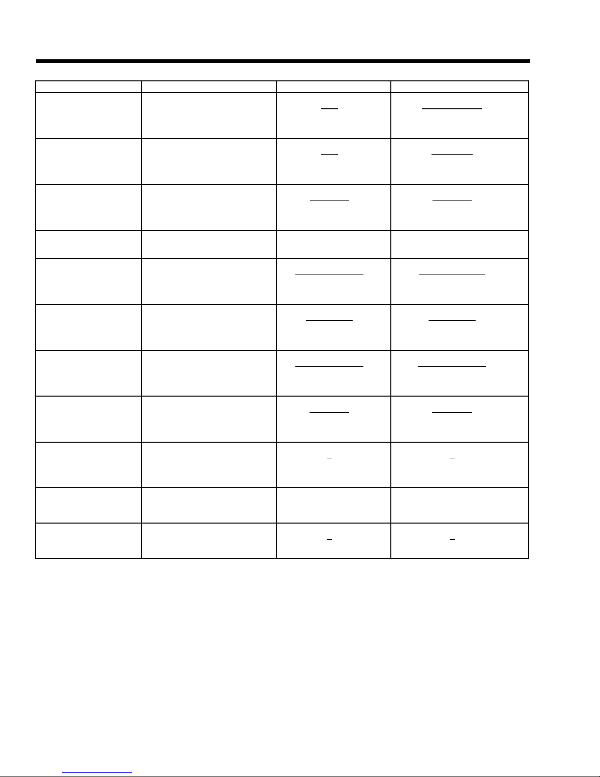
TO FIND KNOWN VALUES 1-PHASE 3-PHASE
KILOWATTS (kW) Volts, Current, Power Factor E x I
E x I x 1.73 x PF
1000 1000
KVA Volts, Current E x I
E x I x 1.73
1000 1000
AMPERES kW, Volts, Power Factor kW x 1000 kW x 1000
E E x 1.73 x PF
WATTS Volts, Amps, Power Factor Volts x Amps E x I x 1.73 x PF
NO. OF ROTOR Frequency, RPM 2 x 60 x Frequency
2 x 60 x frequency
POLES RPM RPM
FREQUENCY RPM, No. of Rotor Poles RPM x Poles RPM x Poles
2 x 60 2 x 60
RPM Frequency, No. of Rotor Poles 2 x 60 x Frequency 2 x 60 x Frequency
Rotor Poles Rotor Poles
kW (required for Motor Horsepower, Efficiency HP x 0.746
HP x 0.746
Motor) Efficiency Efficiency
RESISTANCE Volts, Amperes E E
II
VOLTS Ohm, Amperes I x R I x R
AMPERES Ohms, Volts E E
RR
E = VOLTS I = AMPERES R = RESISTANCE (OHMS) PF = POWER FACTOR
ELECTRICAL FORMULAS
Page 2

SPECIFICATIONS
Page 3
GENERATOR
Models 04389, 04758 Models 04456, 04759 Model 04390, 04760
Rated Max. Continuous Power Capacity (Watts*) 6,000 NG/7,000 LP 12,000 NG/12,000 LP 13,000 NG/15,000 LP†
Rated Voltage 120/240 120/240 120/240
Rated Max. Continuous Load Current (Amps)
120 Volts** 50.0 NG/58.3 LP 100.0 NG/100.0 LP 108.3 NG/125.0 LP
240 Volts 25.0 NG/29.2 LP 50.0 NG/50.0 LP 54.2 NG/62.5 LP
Main Line Circuit Breaker 30 Amp 50 Amp 60 Amp/70 Amp†
Phase 1 1 1
Number of Rotor Poles 2 2 2
Rated AC Frequency 60 Hz 60 Hz 60 Hz
Power Factor 1 1 1
Battery Requirement Group 26/26R Group 26/26R Group 26/26R
12 Volts and 12 Volts and 12 Volts and
350 Cold-cranking 550 Cold-cranking 550 Cold-cranking
Amperes Minimum Amperes Minimum Amperes Minimum
Weight 452 Pounds 470 Pounds 487 Pounds
Output Sound Level @ 23 ft (7m) at full load 68 db (A) 70.5db (A) 71.5 db (A)
Normal Operating Range -20°F (-28.8°C) to 104°F (40°C)
* Maximum wattage and current are subject to and limited by such factors as fuel Btu content, ambient temperature, altitude, engine power and condition, etc. Maximum power decreas-
es about 3.5 percent for each 1,000 feet above sea level; and also will decrease about 1 percent for each 6° C (10° F) above 16° C (60° F) ambient temperature.
** Load current values shown for 120 volts are maximum TOTAL values for two separate circuits. The maximum current in each circuit must not exceed the value stated for 240 volts.
† 15,000 watt with upgrade kit 04578-0. Kit includes power harnesses and 70 amp 2-pole circuit breaker.
ENGINE
Models 04389, 04758 Models 04456, 04759 Models 04390, 04760
Type of Engine GH-410 GT-990 GT-990
Number of Cylinders 1 2 2
Rated Horsepower 14.5 @ 3,600 rpm 26 @ 3,600 rpm 30 @ 3,600 rpm
Displacement 410cc 992cc 992cc
Cylinder Block Aluminum w/Cast Aluminum w/Cast Aluminum w/Cast
Iron Sleeve Iron Sleeve Iron Sleeve
Valve Arrangement Overhead Valves Overhead Valves Overhead Valves
Ignition System Solid-state w/Magneto Solid-state w/Magneto Solid-state w/Magneto
Recommended Spark Plug RC12YC RC12YC RC12YC
Spark Plug Gap 0.76 mm (0.030 inch) 0.5 mm (0.020 inch) 0.5 mm (0.020 inch)
Compression Ratio 8.6:1 9.5:1 9.5:1
Starter 12 VDC 12 VDC 12 VDC
Oil Capacity Including Filter Approx. 1.5 Qts Approx. 1.7 Qts Approx. 1.7 Qts
Recommended Oil Filter Generac Part # 070185 Generac Part # 070185 Generac Part # 070185
Recommended Air Filter Generac Part # 0C8127 Generac Part # 0C8127 Generac Part # 0C8127
Operating RPM 3,600 3,600 3,600
FUEL CONSUMPTION
Model # Natural Gas* LP Vapor**
1/2 Load Full Load 1/2 Load Full Load
04389, 04758 74 105 0.91/33 1.21/44.1
04556, 04759 114 185 1.34/48.9 2.17/79.0
04390, 04760 148.5 240 1.73/63.2 2.80/102.3
* Natural gas is in cubic feet per hour. **LP is in gallons per hour/cubic feet per hour.
STATOR WINDING RESISTANCE VALUES / ROTOR RESISTANCE
Model 04692 Models 04389 Models 04456 Models 04390
04679, 04758 04759 04760
Power Winding: Across 11 & 22 0.190-0.208 ohms 0.223-0.259 ohms 0.115 ohms 0.08/0.08 ohms
Power Winding: Across 33 & 44 0.190-0.208 ohms 0.223-0.259 ohms 0.115 ohms 0.08/0.08 ohms
Excitation Winding: Across 2 & 6 1.442-1.670 ohms 1.53-1.77 ohms 0.745 ohms 0.705 ohms
Engine Run Winding: Across 55 & 66A 0.104-0.120 ohms 0.100-0.169 ohms 0.109 ohms 0.087 ohms
Battery Charge Winding: Across 66 & 77 0.137-0.158 ohms 0.146-0.169 ohms 0.164 ohms 0.130 ohms
Rotor Resistance 15.42-17-85 ohms 11.88-13.76 ohms 15.9 ohms 19.8 ohms
Page 4
SPECIFICATIONS
W
CH
W
(
)
"
S
Ø
30
[
Ø
]
:
]
]
L
UM
[2
]
]
308
[
]
3
[
]
]
04
[
]
]
]
OR
M
0D3739
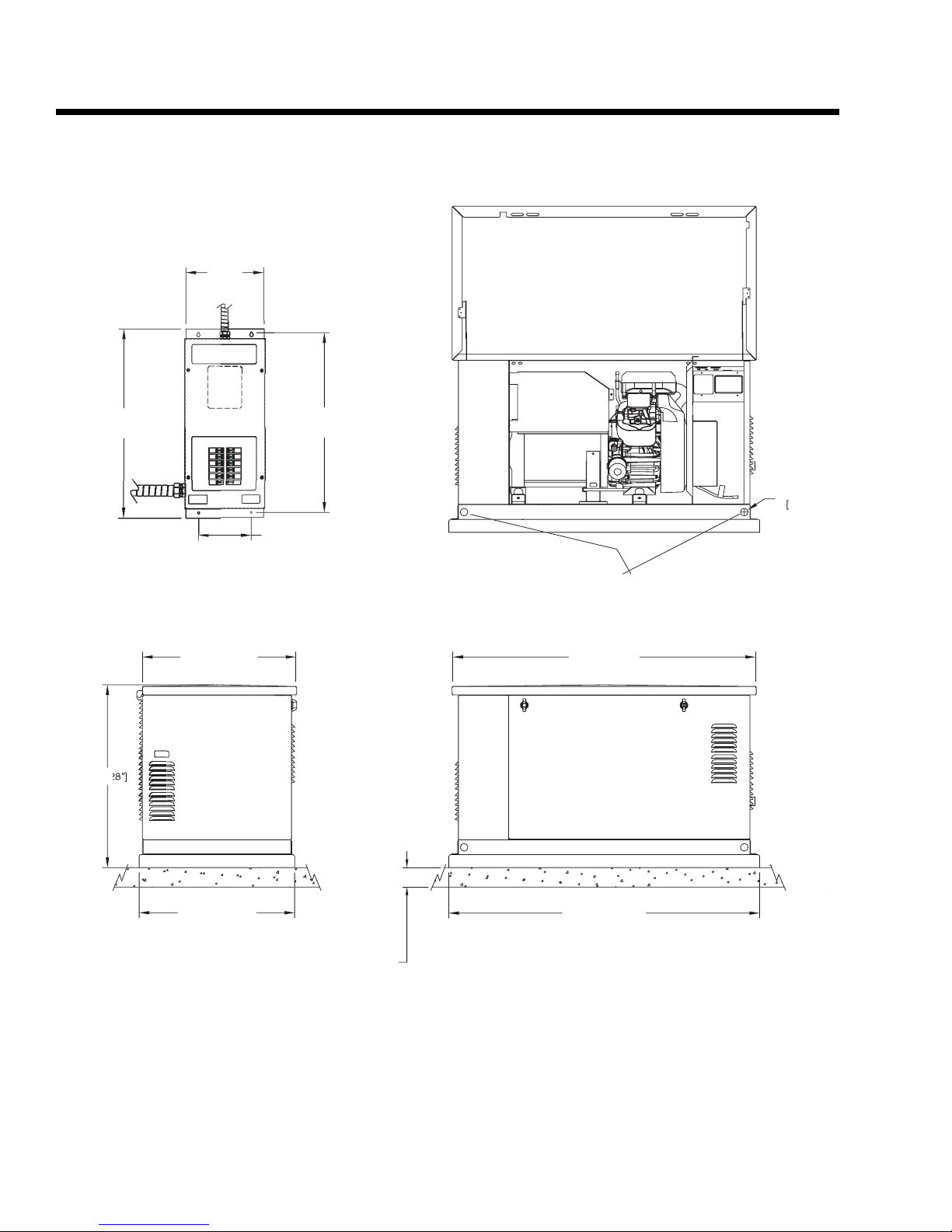
MOUNTING DIMENSIONS
12"
716
74
29.25"
TRANSFER SWIT
IF SUPPLIED
604 [23.5"
207 [8.14"
7
27.7"
LIFTING HOLES 4-CORNER
"DO NOT LIFT BY THE ROOF
1193 [47"
.2mm
1.19"
622 [24.5"
LEFT SIDE VIE
76.2mm [3.00"
PEA GRAVE
MINUM
HOME STANDBY GENERAT
INSTALLATION DIAGRA
1232 [48.5"
FRONT VIE
**ALL DIMENSIONS IN
MILLIMETERS [INCHES
Page 5
SPECIFICATIONS
W
L
UG
T
SSU
"
D
:
]
]
A
T
]
9
]
]
490.7 [19.3"
]
S.
)
OR
M
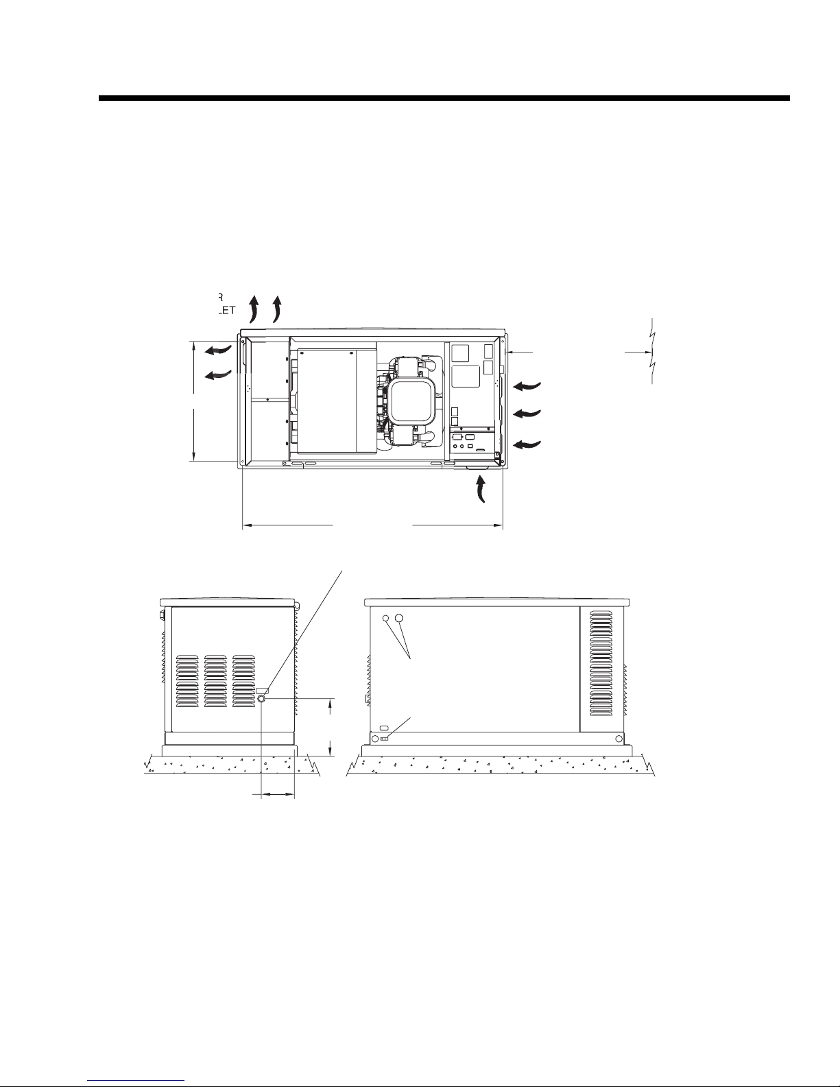
MOUNTING DIMENSIONS
T
914mm [ 36.0"
MINIMUM OPEN ARE
ALL AROUND UNI
14
5.9"
RIGHT SIDE VIE
1172.3 [46.2"
4" NPT FUEL INLE
AS PRE
WATER COLUMN REQUIRE
10.2"
RE OF 11-14
ABLE ACCESS HOLE
REMOVE PLUG FOR ACCESS
ROUNDING L
**ALL DIMENSIONS IN
MILLIMETERS [INCHES
HOME STANDBY GENERAT
INSTALLATION DIAGRA
SPECIFICATIONS
Page 6
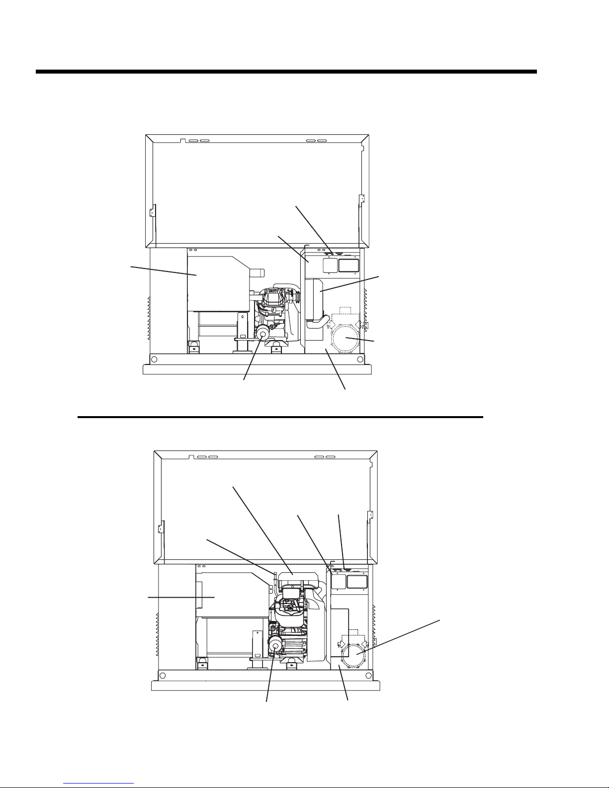
MAJOR FEATURES
12 kW and 15 kW, V-twin GT-990 Engine
7 kW, Single Cylinder GH-410 Engine
CONTROL PANEL
DATA DECAL
EXHAUST
ENCLOSURE
OIL FILTER
BATTERY COMPARTMENT
AIR FILTER
DATA
DECAL
OIL DIPSTICK
CONTROL
PA NE L
AIR FILTER
FUEL REGULATOR
(BEHIND BATTERY COMPARTMENT)
EXHAUST
ENCLOSURE
OIL FILTER
FUEL REGULATOR
(BEHIND BATTERY COMPARTMENT)
BATTERY COMPARTMENT

PART TITLE
1.1 Generator Identification
1.2 Prepackaged Installation Basics
1.3 Preparation Before Use
1.4 Testing, Cleaning and Drying
1.5 Engine-Generator Protective Devices
1.6 Operating Instructions
1.7 Automatic Operating Parameters
PART 1
GENERAL
INFORMATION
Air-cooled, Prepackaged
Automatic Standby Generators
Models:
04389, 04758 (6 kW NG, 7 kW LP)
04456, 04759 (12 kW NG, 12 kW LP)
04390, 04760 (13 kW NG, 15 kW LP)
TABLE OF CONTENTS
Page 7
INTRODUCTION
This Diagnostic Repair Manual has been prepared
especially for the purpose of familiarizing service personnel with the testing, troubleshooting and repair of
air-cooled, prepackaged automatic standby generators. Every effort has been expended to ensure that
information and instructions in the manual are both
accurate and current. However, Generac reserves the
right to change, alter or otherwise improve the product at any time without prior notification.
The manual has been divided into ten PARTS. Each
PART has been divided into SECTIONS. Each SECTION consists of two or more SUBSECTIONS.
It is not our intent to provide detailed disassembly and
reassemble instructions in this manual. It is our intent
to (a) provide the service technician with an understanding of how the various assemblies and systems
work, (b) assist the technician in finding the cause of
malfunctions, and (c) effect the expeditious repair of
the equipment.
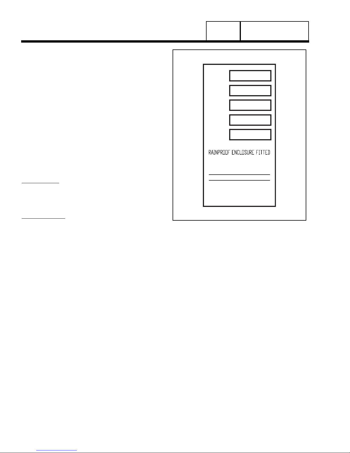
ITEM NUMBER:
Many home standby generators are manufactured to
the unique specifications of the buyer. The Model
Number identifies the specific generator set and its
unique design specifications.
SERIAL NUMBER:
Used for warranty tracking purposes.
Figure 1. A Typical Data Plate
Page 8
PART 1
GENERAL INFORMATION
SECTION 1.1
GENERATOR IDENTIFICATION
Item # 0055555
Serial
Volts
Amps
Watts
1234567
120/240 AC
125/62.5
15000
1 PH, 60 HZ, RPM 3600
CLASS F INSULATION
MAX OPERATING AMBIENT
TEMP - 120F/49C
FOR STANDBY SERVICE
NEUTRAL FLOATING
MAX LOAD UNBALANCED - 50%
GENERAC POWER SYSTEMS
WAUKESHA, WI
MADE IN U.S.A.
Page 9
GENERAL INFORMATION
SECTION 1.2
PREPACKAGED INSTALLATION BASICS
INTRODUCTION
Information in this section is provided so that the service technician will have a basic knowledge of installation requirements for prepackaged home standby
systems. Problems that arise are often related to poor
or unauthorized installation practices.
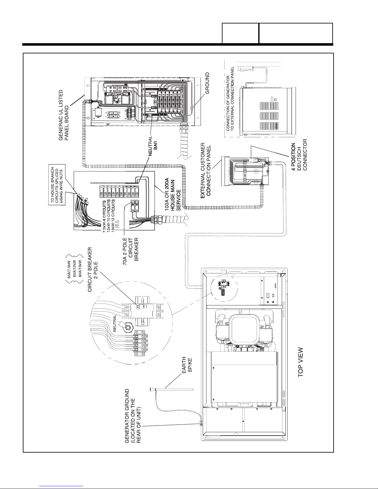
A typical prepackaged home standby electric system
is shown in Figure 1 (next page). Installation of such a
system includes the following:
• Selecting a Location
• Grounding the generator.
• Providing a fuel supply.
• Mounting the load center.
• Connecting power source and load lines.
• Connecting system control wiring.
• Post installation tests and adjustments.
SELECTING A LOCATION
Install the generator set as close as possible to the
electrical load distribution panel(s) that will be powered by the unit, ensuring that there is proper ventilation for cooling air and exhaust gases. This will
reduce wiring and conduit lengths. Wiring and conduit
not only add to the cost of the installation, but excessively long wiring runs can result in a voltage drop.
GROUNDING THE GENERATOR
The National Electric Code requires that the frame
and external electrically conductive parts of the generator be property connected to an approved earth
ground. Local electrical codes may also require proper grounding of the unit. For that purpose, a grounding lug is attached to the unit. Grounding may be
accomplished by attaching a stranded copper wire of
the proper size to the generator grounding lug and to
an earth-driven copper or brass grounding-rod (electrode). Consult with a local electrician for grounding
requirements in your area.
THE FUEL SUPPLY
Prepackaged units with air-cooled engines were operated, tested and adjusted at the factory using natural
gas as a fuel. These air-cooled engine units can be
converted to use LP (propane) gas by making a few
adjustments for best operation and power.
LP (propane) gas is usually supplied as a liquid in
pressure tanks. Both the air-cooled and the liquid
cooled units require a “vapor withdrawal” type of fuel
supply system when LP (propane) gas is used. The
vapor withdrawal system utilizes the gaseous fuel
vapors that form at the top of the supply tank.
The pressure at which LP gas is delivered to the generator fuel solenoid valve may vary considerably,
depending on ambient temperatures. In cold weather,
supply pressures may drop to “zero”. In warm weather, extremely high gas pressures may be encountered. A primary regulator is required to maintain correct gas supply pressures.
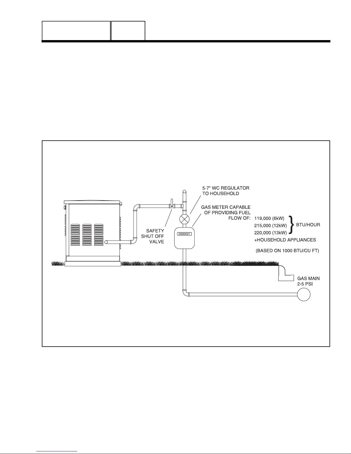
Current recommended gaseous fuel pressure at the inlet
side of the generator fuel solenoid valve is as follows:
LP NG
Minimum water column 11 inches 5 inches
Maximum water column 14 inches 7 inches
Note: Some older NG product was rated at 11-14
inches water column.
A primary regulator is required to ensure that proper
fuel supply pressures are maintained.
DANGER: LP AND NATURAL GAS ARE BOTH
HIGHLY EXPLOSIVE. GASEOUS FUEL LINES
MUST BE PROPERLY PURGED AND TESTED
FOR LEAKS BEFORE THIS EQUIPMENT IS
PLACED INTO SERVICE AND PERIODICALLY
THEREAFTER. PROCEDURES USED IN
GASEOUS FUEL LEAKAGE TESTS MUST
COMPLY STRICTLY WITH APPLICABLE FUEL
GAS CODES. DO NOT USE FLAME OR ANY
SOURCE OF HEAT TO TEST FOR GAS
LEAKS. NO GAS LEAKAGE IS PERMITTED.
LP GAS IS HEAVIER THAN AIR AND TENDS
TO SETTLE IN LOW AREAS. NATURAL GAS
IS LIGHTER THAN AIR AND TENDS TO SETTLE IN HIGH PLACES. EVEN THE SLIGHTEST
SPARK CAN IGNITE THESE FUELS AND
CAUSE AN EXPLOSION.
Use of a flexible length of hose between the generator fuel line connection and rigid fuel lines is required.
This will help prevent line breakage that might be
caused by vibration or if the generator shifts or settles. The flexible fuel line must be approved for use
with gaseous fuels.
Flexible fuel line should be kept as straight as possible between connections. The bend radius for flexible
fuel line is nine (9) inches. Exceeding the bend radius
can cause the fittings to crack.
THE TRANSFER SWITCH / LOAD CENTER
A transfer switch is required by electrical code, to prevent electrical feedback between the utility and standby power sources, and to transfer electrical loads
from one power supply to another safely.
PREPACKAGED TRANSFER SWITCHES:
Instructions and information on prepackaged transfer
switches may be found in Part 3 of this manual.
!
PART 1
PART 1
Page 10
GENERAL INFORMATION
SECTION 1.2
PREPACKAGED INSTALLATION BASICS
Figure 1. Typical Prepackaged Installation
GENERAL INFORMATION
SECTION 1.2
PREPACKAGED INSTALLATION BASICS
POWER SOURCE AND LOAD LINES
The utility power supply lines, the standby (generator)
supply lines, and electrical load lines must all be connected to the proper terminal lugs in the transfer
switch. The following rules apply:In 1-phase systems
with a 2-pole transfer switch, connect the two utility
source hot lines to Transfer Switch Terminal Lugs N1
and N2. Connect the standby source hot lines (E1,
E2) to Transfer Switch Terminal Lugs E1 and E2.
Connect the load lines from Transfer Switch Terminal
Lugs T1 and T2 to the electrical load circuit. Connect
UTILITY, STANDBY and LOAD neutral lines to the
neutral block in the transfer switch.
SYSTEM CONTROL INTERCONNECTIONS
Prepackaged home standby generators are equipped
with a terminal board identified with the following terminals: (a) UTILITY 1, (b) UTILITY 2, (c) 23, and (d)
194. Prepackaged load centers house an identically
marked terminal board. When these four terminals
are properly interconnected, dropout of utility source
voltage below a preset value will result in automatic
generator startup and transfer of electrical loads to
the “Standby” source. On restoration of utility source
voltage above a preset value will result in retransfer
back to that source and generator shutdown.
PART 1
Page 11
Figure 2. Proper Fuel Installation
GENERAL
The installer must ensure that the home standby generator has been properly installed. The system must
be inspected carefully following installation. All applicable codes, standards and regulations pertaining to
such installations must be strictly complied with. In
addition, regulations established by the Occupational
Safety and Health Administration (OSHA) must be
complied with.
Prior to initial startup of the unit, the installer must
ensure that the engine-generator has been properly
prepared for use. This includes the following:
• An adequate supply of the correct fuel must be
available for generator operation.
• The engine must be properly serviced with the recommended oil.
FUEL REQUIREMENTS
Generators with air-cooled engine have been factory
tested and adjusted using natural gas as a fuel. If LP
(propane) gas is to be used at the installation site,
adjustment of the generator fuel regulator will be
required for best performance. Refer to Test 63,
“Check Fuel Regulator” in Section 4.4 for fuel regulator adjustment procedures.
• When natural gas is used as a fuel, it should be
rated at least 1000 BTU’s per cubic foot.
• When LP (propane) gas is used as a fuel, it should
be rated at 2520 BTU’s per cubic foot.
ENGINE OIL RECOMMENDATIONS
The primary recommended oil for units with aircooled, single cylinder or V-Twin engines is synthetic
oil. Synthetic oil provides easier starts in cold weather
and maximum engine protection in hot weather. Use
high quality detergent oil that meets or exceeds API
(American Petroleum Institute) Service class SG, SH,
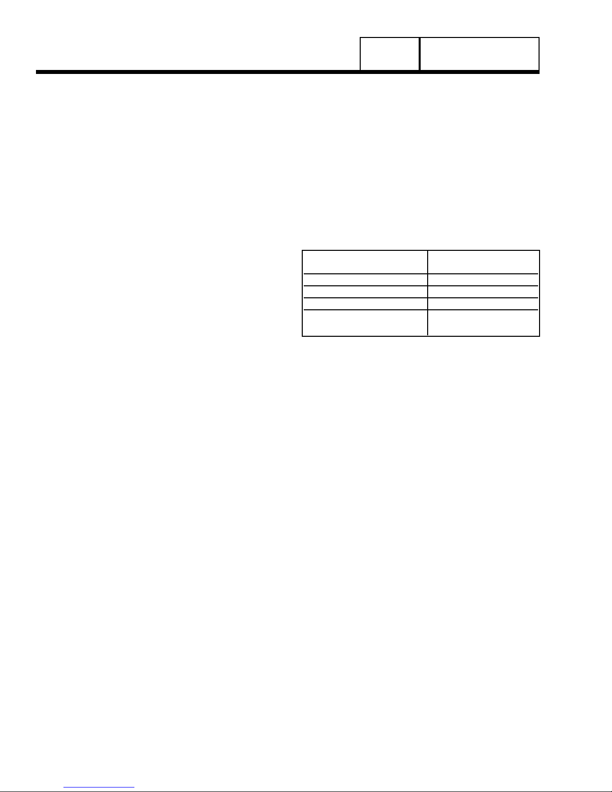
or SJ requirements for gasoline engines. The following chart lists recommended viscosity ranges for the
lowest anticipated ambient temperatures.
Engine crankcase oil capacities for the engines covered in this manual can be found in the specifications
section at the beginning of the book.
LOWEST ANTICIPATED AIR COOLED ENGINE
AMBIENT TEMPERATURE RECOMMENDED OIL
Above 60° F. (16° C.) Use SAE 30 oil
20°-59° F. (-7° to 15° C.) Use SAE 10W-30 oil
Below 20° F. (-7° C.) SAE 5W-20/5W-30 oil
For all seasons Use SAE 5W-30
Synthetic oil
PART 1
GENERAL INFORMATION
SECTION 1.3
PREPARATION BEFORE USE
Page 12
Page 13
GENERAL INFORMATION
SECTION 1.4
TESTING, CLEANING AND DRYING
VISUAL INSPECTION
When it becomes necessary to test or troubleshoot a
generator, it is a good practice to complete a thorough visual inspection. Remove the access covers
and look closely for any obvious problems. Look for
the following:
• Burned or broken wires, broken wire connectors,
damaged mounting brackets, etc.
• Loose or frayed wiring insulation, loose or dirty connections.
• Check that all wiring is well clear of rotating parts.
• Verify that the Generator properly connected for the
correct rated voltage. This is especially important
on new installations. See Section 1.2, “AC
Connection Systems”.
• Look for foreign objects, loose nuts, bolts and other
fasteners.
• Clean the area around the Generator. Clear away
paper, leaves, snow, and other objects that might
blow against the generator and obstruct its air
openings.
METERS
Devices used to measure electrical properties are
called meters. Meters are available that allow one to
measure (a) AC voltage, (b) DC voltage, (c) AC frequency, and (d) resistance In ohms. The following
apply:
• To measure AC voltage, use an AC voltmeter.
• To measure DC voltage, use a DC voltmeter.
• Use a frequency meter to measure AC frequency In
“Hertz” or “cycles per second”.
• Use an ohmmeter to read circuit resistance, in “ohms”.
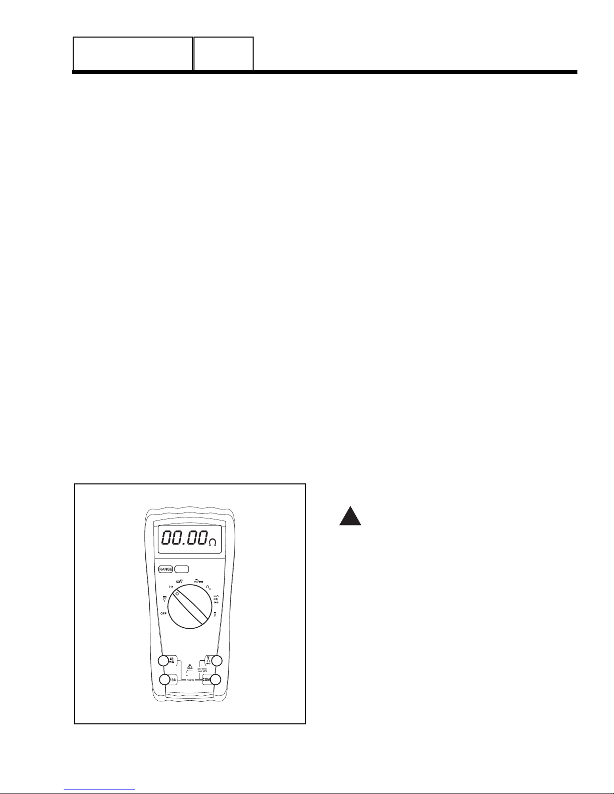
Figure 1. Digital VOM
THE VOM
A meter that will permit both voltage and resistance to
be read is the “volt-ohm-milliammeter” or “VOM”.
Some VOM’s are of the analog type (not shown).
These meters display the value being measured by
physically deflecting a needle across a graduated
scale. The scale used must be interpreted by the user.
Digital VOM’s (Figure 1) are also available and are
generally very accurate. Digital meters display the
measured values directly by converting the values to
numbers.
NOTE: Standard AC voltmeters react to the AVERAGE value of alternating current. When working
with AC, the effective value is used. For that reason a different scale is used on an AC voltmeter.
The scale is marked with the effective or “rms”
value even though the meter actually reacts to the
average value. That is why the AC voltmeter will
give an Incorrect reading if used to measure
direct current (DC).
MEASURING AC VOLTAGE
An accurate AC voltmeter or a VOM may be used to
read the generator AC output voltage. The following
apply:
1. Always read the generator AC output voltage only at the
unit’s rated operating speed and AC frequency.
2. The generator voltage regulator can be adjusted for correct output voltage only while the unit is operating at its
correct rated speed and frequency.
3. Only an AC voltmeter may be used to measure AC voltage. DO NOT USE A DC VOLTMETER FOR THIS
PURPOSE.
DANGER!: GENERATORS PRODUCE HIGH
AND DANGEROUS VOLTAGES. CONTACT
WITH HIGH VOLTAGE TERMINALS WILL
RESULT IN DANGEROUS AND POSSIBLY
LETHAL ELECTRICAL SHOCK.
MEASURING DC VOLTAGE
A DC voltmeter or a VOM may be used to measure
DC voltages. Always observe the following rules:
1. Always observe correct DC polarity.
a. Some VOM’s may be equipped with a
polarity switch.
b. On meters that do not have a polarity
switch, DC polarity must be reversed by
reversing the test leads.
2. Before reading a DC voltage, always set the meter to a
higher voltage scale than the anticipated reading. if in
doubt, start at the highest scale and adjust the scale
downward until correct readings are obtained.
!
PART 1

PART 1
3. The design of some meters is based on the “current
flow” theory while others are based on the “electron
flow” theory.
a. The “current flow” theory assumes that
direct current flows from the positive (+) to
the negative (-).
b. The “electron flow” theory assumes that cur-
rent flows from negative (-) to positive (+).
NOTE: When testing generators, the “current
flow” theory is applied. That is, current is
assumed to flow from positive (+) to negative (-).
MEASURING AC FREQUENCY
The generator AC output frequency is proportional to
rotor speed. Generators equipped with a 2-pole rotor
must operate at 3600 rpm to supply a frequency of 60
Hertz. Units with 4-pole rotor must run at 1800 rpm to
deliver 60 Hertz.
Correct engine and rotor speed is maintained by an
engine speed governor. For models rated 60 Hertz,
the governor is generally set to maintain a no-load
frequency of about 62 Hertz with a corresponding output voltage of about 124 volts AC line-to-neutral.
Engine speed and frequency at no-load are set slightly high to prevent excessive rpm and frequency droop
under heavy electrical loading.
MEASURING CURRENT
To read the current flow, in AMPERES, a clamp-on
ammeter may be used. This type of meter indicates
current flow through a conductor by measuring the
strength of the magnetic field around that conductor.
The meter consists essentially of a current transformer with a split core and a rectifier type instrument
connected to the secondary. The primary of the current transformer is the conductor through which the
current to be measured flows. The split core allows
the Instrument to be clamped around the conductor
without disconnecting it.
Figure 2. Clamp-On Ammeter
Figure 3. A Line-Splitter
Current flowing through a conductor may be measured safely and easily. A line-splitter can be used to
measure current in a cord without separating the conductors.
NOTE: If the physical size of the conductor or
ammeter capacity does not permit all lines to be
measured simultaneously, measure current flow
in each individual line. Then, add the Individual
readings.
MEASURING RESISTANCE
The volt-ohm-milliammeter may be used to measure
the resistance in a circuit. Resistance values can be
very valuable when testing coils or windings, such as
the stator and rotor windings.
When testing stator windings, keep in mind that the
resistance of these windings is very low. Some
meters are not capable of reading such a low resistance and will simply read CONTINUITY.
If proper procedures are used, the following conditions can be detected using a VOM:
• A “short-to-ground” condition in any stator or rotor
winding.
• Shorting together of any two parallel stator windings.
• Shorting together of any two isolated stator windings.
• An open condition in any stator or rotor winding.
Component testing may require a specific resistance
value or a test for INFINITY or CONTINUITY. Infinity
is an OPEN condition between two electrical points,
which would read as no resistance on a VOM.
Continuity is a closed condition between two electrical
points, which would be indicated as very low resistance or ZERO on a VOM.
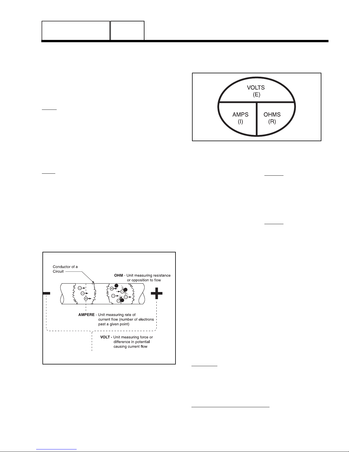
ELECTRICAL UNITS
AMPERE:
The rate of electron flow in a circuit is represented by
the AMPERE. The ampere is the number of electrons
flowing past a given point at a given time. One
AMPERE is equal to just slightly more than six thousand million billion electrons per second.
Page 14
GENERAL INFORMATION
SECTION 1.4
TESTING, CLEANING AND DRYING
GENERAL INFORMATION
SECTION 1.4
TESTING, CLEANING AND DRYING
With alternating current (AC), the electrons flow first
in one direction, then reverse and move in the opposite direction. They will repeat this cycle at regular
intervals. A wave diagram, called a “sine wave”
shows that current goes from zero to maximum positive value, then reverses and goes from zero to maximum negative value. Two reversals of current flow is
called a cycle. The number of cycles per second is
called frequency and is usually stated in “Hertz”.
VOLT:
The VOLT is the unit used to measure electrical
PRESSURE, or the difference in electrical potential
that causes electrons to flow. Very few electrons will
flow when voltage is weak. More electrons will flow as
voltage becomes stronger. VOLTAGE may be considered to be a state of unbalance and current flow as an
attempt to regain balance. One volt is the amount of
EMF that will cause a current of 1 ampere to flow
through 1 ohm of resistance.
OHM:
The OHM is the unit of RESISTANCE. In every circuit
there is a natural resistance or opposition to the flow
of electrons. When an EMF is applied to a complete
circuit, the electrons are forced to flow in a single
direction rather than their free or orbiting pattern. The
resistance of a conductor depends on (a) its physical
makeup, (b) its cross-sectional area, (c) its length,
and (d) its temperature. As the conductor’s temperature increases, its resistance increases in direct proportion. One (1) ohm of resistance will permit one (1)
ampere of current to flow when one (1) volt of electromotive force (EMF) is applied.
Figure 4. Electrical Units
OHM’S LAW
A definite and exact relationship exists between
VOLTS, OHMS and AMPERES. The value of one
can be calculated when the value of the other two
are known. Ohm’s Law states that in any circuit the
current will increase when voltage increases but
resistance remains the same, and current will
decrease when resistance Increases and voltage
remains the same.
Figure 5.
If AMPERES is unknown while VOLTS and OHMS
are known, use the following formula:
AMPERES =
VOLTS
OHMS
If VOLTS is unknown while AMPERES and OHMS
are known, use the following formula:
VOLTS = AMPERES x OHMS
If OHMS is unknown but VOLTS and AMPERES are
known, use the following:
OHMS
=
VOLTS
AMPERES
INSULATION RESISTANCE
The insulation resistance of stator and rotor windings
is a measurement of the integrity of the insulating
materials that separate the electrical windings from
the generator steel core. This resistance can
degrade over time or due to such contaminants as
dust, dirt, oil, grease and especially moisture. In
most cases, failures of stator and rotor windings is
due to a breakdown in the insulation. And, in many
cases, a low insulation resistance is caused by moisture that collects while the generator is shut down.
When problems are caused by moisture buildup on
the windings, they can usually be corrected by drying the windings. Cleaning and drying the windings
can usually eliminate dirt and moisture built up in the
generator windings.
THE MEGOHMMETER
GENERAL:
A megohmmeter, often called a “megger”, consists of
a meter calibrated in megohms and a power supply.
Use a power supply of 500 volts when testing stators
or rotors. DO NOT APPLY VOLTAGE LONGER
THAN ONE (1) SECOND.
TESTING STATOR INSULATION:
All parts that might be damaged by the high megger
voltages must be disconnected before testing. Isolate
all stator leads (Figure 2) and connect all of the stator
PART 1
Page 15
PART 1
leads together. FOLLOW THE MEGGER MANUFACTURER’S INSTRUCTIONS CAREFULLY.
Use a megger power setting of 500 volts. Connect
one megger test lead to the junction of all stator
leads, the other test lead to frame ground on the stator can. Read the number of megohms on the meter.
The MINIMUM acceptable megger reading for stators
may be calculated using the following formula:
EXAMPLE: Generator is rated at 120 volts AC.
Divide “120” by “1000” to obtain “0.12”. Then add
“1” to obtain “1.12” megohms. Minimum
Insulation resistance for a 120 VAC stator is 1.12
megohms.
If the stator insulation resistance is less than the calculated minimum resistance, clean and dry the stator.
Then, repeat the test. If resistance is still low, replace
the stator.
Use the Megger to test for shorts between isolated
windings as outlined “Stator Insulation Tests”.
Also test between parallel windings. See “Test
Between Windings” on next page.
TESTING ROTOR INSULATION:
Apply a voltage of 500 volts across the rotor positive
(+) slip ring (nearest the rotor bearing), and a clean
frame ground (i.e. the rotor shaft). DO NOT
EXCEED 500 VOLTS AND DO NOT APPLY VOLTAGE LONGER THAN 1 SECOND. FOLLOW THE
MEGGER MANUFACTURER’S INSTRUCTIONS
CAREFULLY.
ROTOR MINIMUM INSULATION RESISTANCE:
1.5 megohms
CAUTION: Before attempting to measure
Insulation resistance, first disconnect and
Isolate all leads of the winding to be tested.
Electronic components, diodes, surge protectors, relays, voltage regulators, etc., can be
destroyed if subjected to high megger voltages.
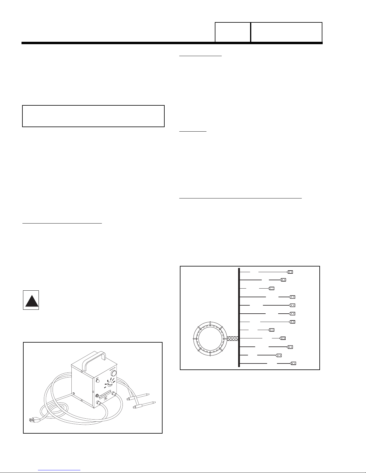
Figure 1. One Type of Hi-Pot Tester
HI-POT TESTER:
A “Hi-Pot” tester is shown in Figure 1. The model
shown is only one of many that are commercially
available. The tester shown is equipped with a voltage selector switch that permits the power supply
voltage to be selected. It also mounts a breakdown
lamp that will illuminate to indicate an insulation
breakdown during the test.
STATOR INSULATION RESISTANCE TEST
GENERAL:
Units with air-cooled engines are equipped with (a)
dual stator AC power windings, (b) an excitation or
DPE winding, (c) a battery charge winding and (d) an
engine run winding. Insulation tests of the stator consist of (a) testing all windings to ground, (b) testing
between isolated windings, and (c) testing between
parallel windings. Figure 2 is a pictorial representation
of the various stator leads on units with air-cooled
engine.
TESTING ALL STATOR WINDINGS TO GROUND:
1. Disconnect stator output leads 11 and 44 from the gen-
erator main line circuit breaker.
2. Remove stator output leads 22 and 33 from the neutral
connection and separate the two leads.
3. Disconnect C2 connector from the side of the control
panel. The C2 connector is the closest to the back
panel (see Figure 9, Section 6).
Figure 2. Stator Winding Leads
4. Connect the terminal ends of Wires 11, 22, 33 and 44
together. Make sure the wire ends are not touching any
part of the generator frame or any terminal.
5. Connect the red test probe of the Hi-Pot tester to the
joined terminal ends of stator leads 11, 22, 33 and 44.
Connect the black tester lead to a clean frame ground
on the stator can. With tester leads connected in this
manner, proceed as follows:
Page 16
GENERAL INFORMATION
SECTION 1.4
TESTING, CLEANING AND DRYING
MINIMUM INSULATION
GENERATOR RATED VOLTS
RESISTANCE =
__________________________
+1
(in “Megohms”)
1000
!
2
6
11P
11S
22P
22S
33
44
55
66A
66
77
GENERAL INFORMATION
SECTION 1.4
TESTING, CLEANING AND DRYING
PART 1
a.Turn the Hi-Pot tester switch OFF.
b.Plug the tester cord into a 120 volt AC wall
socket and set its voltage selector switch to
“1500 volts”.
c.Turn the tester switch ON and observe the
breakdown lamp on tester. DO NOT APPLY
VOLTAGE LONGER THAN 1 SECOND. After
one (1) second, turn the tester switch OFF.
If the breakdown lamp comes on during the one-second test, the stator should be cleaned and dried. After
cleaning and drying, repeat the insulation test. If, after
cleaning and drying, the stator fails the second test,
the stator assembly should be replaced.
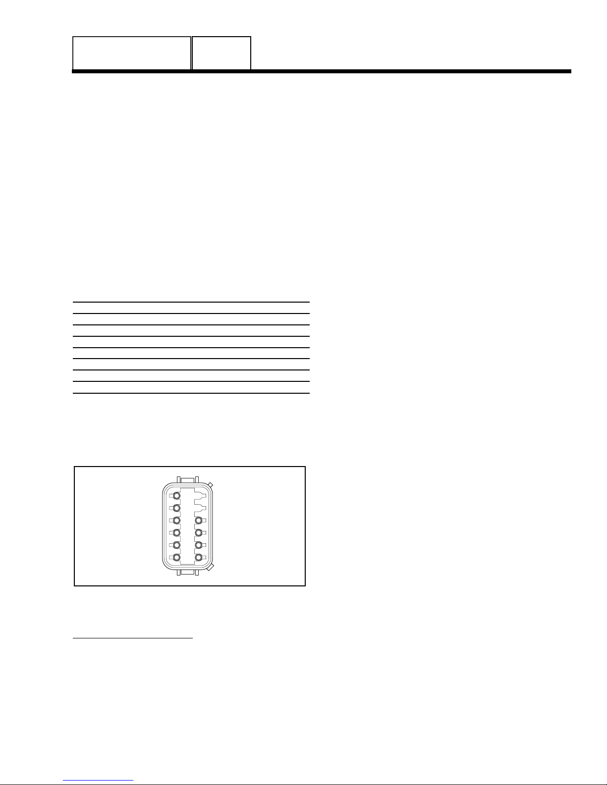
6. Now proceed to the C2 connector. Each winding will be
individually tested for a short to ground. Insert a large
paper clip (or similar item) into the C2 connector at the
following pin locations:
Pin Wire Winding
Location Number
1 77 Battery Charge
2 66 Battery Charge
3 66A Engine Run
4 55 Engine Run
5 22 Sense Lead Power
6 11 Sense Lead Power
7 6 Excitation
8 2 Excitation
Next refer to Steps 5a through 5c of the Hi-Pot
procedure.
Example: Insert paper clip into Pin 1, Hi-Pot from
Pin 1 (Wire 77) to ground. Proceed to Pin 2, Pin 3,
etc. through Pin 8.
Figure 3. C2 Connector Pin Location Numbers
(Female Side)
TEST BETWEEN WINDINGS:
1. Insert a large paper clip into Pin Location 1 (Wire 77).
Connect the red tester probe to the paper clip. Connect
the black tester probe to Stator Lead 11. Refer to Steps
5a through 5c of “TESTING ALL STATOR WINDINGS
TO GROUND” on previous page.
2. Repeat Step 1 at Pin Location 3 (Wire 66A) and Stator
Lead 11.
3. Repeat Step 1 at Pin Location 7 (Wire 6). and Stator
Lead 11.
4. Connect the red test probe to Stator Lead 33. Connect
the black test probe to Stator Lead 11. Refer to Steps
5a through 5c of “TESTING ALL STATOR WINDINGS
TO GROUND” on previous page.
5. Insert a large paper clip into Pin Location No. 1 (Wire
77). Connect the red tester probe to the paper clip.
Connect the black tester probe to Stator Lead 33. Refer
to Steps 5a through 5c of “TESTING ALL STATOR
WINDINGS TO GROUND” on the previous page.
6. Repeat Step 5 at Pin Location 3 (Wire 66A) and Stator
Lead 33.
7. Repeat Step 5 at Pin Location 7 (Wire 6) and Stator
Lead 33.
For the following Steps (8 through 10) an additional
large paper clip (or similar item) will be needed:
8. Insert a large paper clip into Pin Location 1 (Wire 77).
Connect the red tester probe to the paper clip. Insert the
additional large paper clip into Pin Location 3 (Wire
66A). Connect the black tester probe to this paper clip.
Refer to Steps 5a through 5c of “TESTING ALL STATOR WINDINGS TO GROUND” on the previous page.
9. Insert a large paper clip into Pin Location 1 (Wire 77).
Connect the red tester probe to the paper clip. Insert the
additional large paper clip into Pin Location 7 (Wire 6).
Connect the black tester probe to this paper clip. Refer
to Steps 5a through 5c of “TESTING ALL STATOR
WINDINGS TO GROUND” on the previous page.
10.Insert a large paper clip into Pin Location 3 (Wire 66A).
Connect the red tester probe to the paper clip. Insert the
additional large paper clip into Pin Location 7 (Wire 6).
Connect the black tester probe to this paper clip. Refer
to Steps 5a through 5c of “TESTING ALL STATOR
WINDINGS TO GROUND” on the previous page.
ROTOR INSULATION RESISTANCE TEST
Before attempting to test rotor insulation, the brush
holder must be completely removed. The rotor must
be completely isolated from other components before
starting the test. Attach all leads of all stator windings
to ground.
1. Connect the red tester lead to the positive (+) slip ring
(nearest the rotor bearing).
2. Connect the black tester probe to a clean frame ground,
such as a clean metal part of the rotor shaft.
3. Turn the tester switch OFF.
4. Plug the tester into a 120 volts AC wall socket and set
the voltage switch to “1500 volts”.
Page 17
1
2
3
4
5
6
12
11
10
9
8
7

PART 1
GENERAL INFORMATION
SECTION 1.4
TESTING, CLEANING AND DRYING
5. Turn the tester switch “On” and make sure the pilot light
has turned on.
6. Observe the breakdown lamp, then turn the tester switch
OFF. DO NOT APPLY VOLTAGE LONGER THAN ONE
(1) SECOND.
If the breakdown lamp came on during the one (1)
second test, cleaning and drying of the rotor may be
necessary. After cleaning and drying, repeat the insulation breakdown test. If breakdown lamp comes on
during the second test, replace the rotor assembly.
Figure 4. Testing Rotor Insulation
CLEANING THE GENERATOR
Caked or greasy dirt may be loosened with a soft
brush or a damp cloth. A vacuum system may be
used to clean up loosened dirt. Dust and dirt may
also be removed using dry, low-pressure air (25 psi
maximum).
CAUTION: Do not use sprayed water to clean
the generator. Some of the water will be
retained on generator windings and terminals, and may cause very serious problems.
DRYING THE GENERATOR
To dry a generator, proceed as follows:
1. Open the generator main circuit breaker. NO ELECTRICAL LOADS MUST BE APPLIED TO THE GENERATOR WHILE DRYING.
2. Disconnect all Wires 4 from the voltage regulator.
3. Provide an external source to blow warm, dry air
through the generator interior (around the rotor and stator windings. DO NOT EXCEED 185° F. (85° C.).
4. Start the generator and let it run for 2 or 3 hours.
5. Shut the generator down and repeat the stator and rotor
insulation resistance tests.
!
Page 18
POSITIVE (+)
TEST LEAD
GENERAL INFORMATION
SECTION 1.5
ENGINE-GENERATOR PROTECTIVE DEVICES
GENERAL
Standby electric power generators will often run unattended for long periods of time. Such operating parameters as (a) engine oil pressure, (b) engine temperature, (c) engine operating speed, and (d) engine
cranking and startup are not monitored by an operator
during automatic operation. Because engine operation will not be monitored, the use of engine protective
safety devices is required to prevent engine damage
in the event of a problem.
Prepackaged generator engines mount several
engine protective devices. These devices work in
conjunction with a circuit board, to protect the engine
against such operating faults as (a) low engine oil
pressure, (b) high temperature, (c) overspeed, and (d)
overcrank. On occurrence of any one or more of
those operating faults, circuit board action will effect
an engine shutdown.
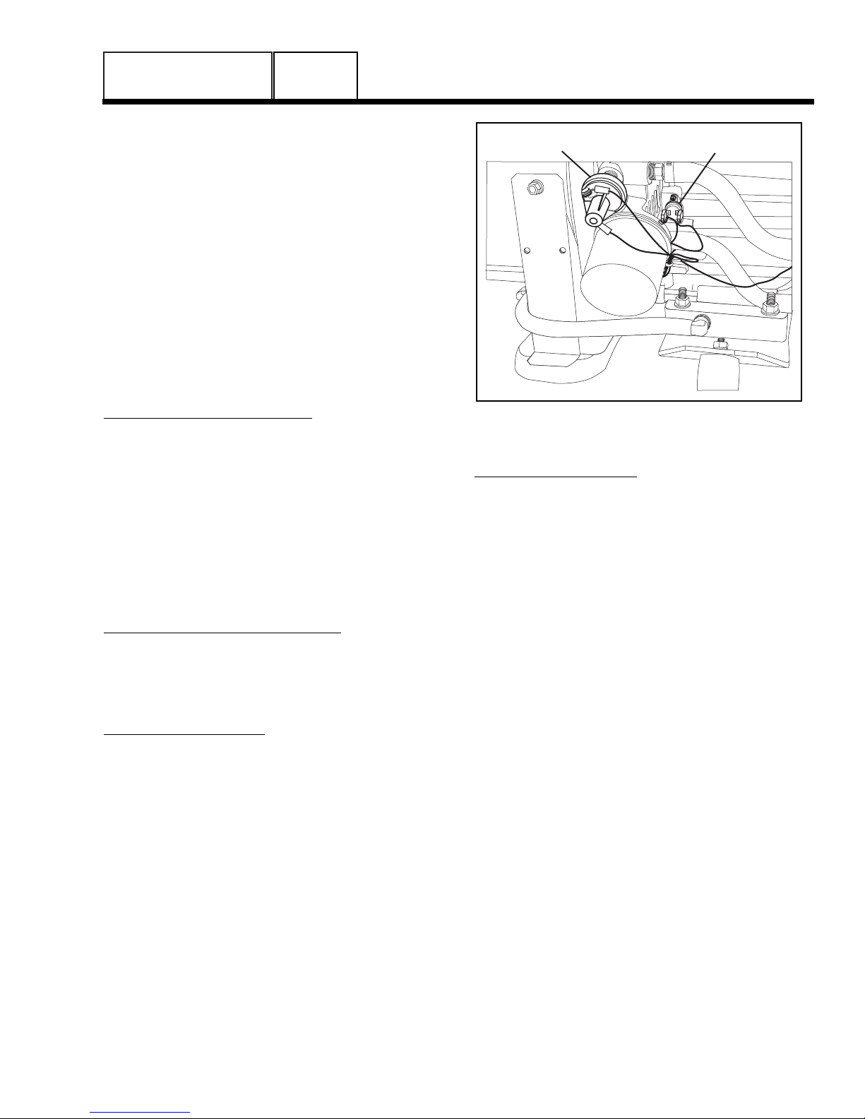
LOW OIL PRESSURE SHUTDOWN:
See Figure 1. An oil pressure switch is mounted on
the engine oil filter adapter. This switch has normally
closed contacts that are held open by engine oil pressure during cranking and startup. Should oil pressure
drop below approximately 10 psi, the switch contacts
will close. On closure of the switch contacts, a Wire
86 circuit from the circuit board will be connected to
ground. Circuit board action will then de-energize a
“run relay” (on the circuit board). The run relay’s normally open contacts will then open and a 12 volts DC
power supply to a Wire 14 circuit will then be terminated. This will result in closure of a fuel shutoff solenoid and loss of engine ignition.
HIGH OIL TEMPERATURE SHUTDOWN:
An oil temperature switch (Figure 1) is mounted on
the engine block. The thermal switch has normally
open contacts that will close if oil temperature should
exceed approximately 284° F (140° C). This will result
in the same action as a low oil pressure shutdown.
OVERSPEED SHUTDOWN:
During engine cranking and operation, the circuit
board receives AC voltage and frequency signals
from the generator engine run windings, via Wire 66A.
Should the AC frequency exceed approximately 72Hz
(4320 rpm), circuit board action will de-energize a
“run relay” (mounted on the circuit board). The relay’s
contacts will open, to terminate engine ignition and
close a fuel shutoff solenoid. The engine will then
shut down. This feature protects the engine-generator
against damaging overspeeds.
NOTE: The circuit board also uses engine run
winding output to terminate engine cranking at
approximately 30 Hz (1800 rpm). In addition, the
engine run winding output is used by the circuit
board as an “engine running” signal The circuit
board will not initiate transfer of electrical loads
to the “Standby” source unless the engine is running at 30 Hz or above.
Figure 1. Engine Protective Switches on an
Air-Cooled Engine
OVERCRANK SHUTDOWN:
Automatic engine cranking and startup normally
occurs when the circuit board senses that utility
source voltage has dropped below approximately 60
percent of its nominal rated voltage and remains at
that low level longer than fifteen (15) seconds. At the
end of fifteen (15) seconds, circuit board action will
energize a crank relay and a run relay (both relays
are on the circuit board). On closure of the crank relay
contacts, circuit board action will deliver 12 volts DC
to a starter contactor relay (SCR, for v-twin models)
or a starter contactor (SC, for single cylinder models).
The control contactor will energize and battery power
will be delivered to the starter motor (SM). The engine
will then crank.
During a manual startup (AUTO-OFF-MANUAL
switch at MANUAL), action is the same as during an
automatic start, except that cranking will begin immediately when the switch is set to MANUAL.
Circuit board action (during both a manual and an
automatic start) will hold the crank relay energized for
15 seconds on. The relay will then de-energize for 15
seconds off. It will then energize for seven (7) seconds on and de-energize for seven (7) seconds off. It
will repeat this same cycle for another 45 seconds.
If the engine has not started after approximately 90
seconds of these crank-rest cycles, cranking will automatically terminate and shutdown will occur. The circuit board uses AC signals from the stator engine run
winding as an indication that the engine has started.
PART 1
Page 19
LOW OIL SWITCH HIGH TEMP SWITCH
CONTROL PANEL
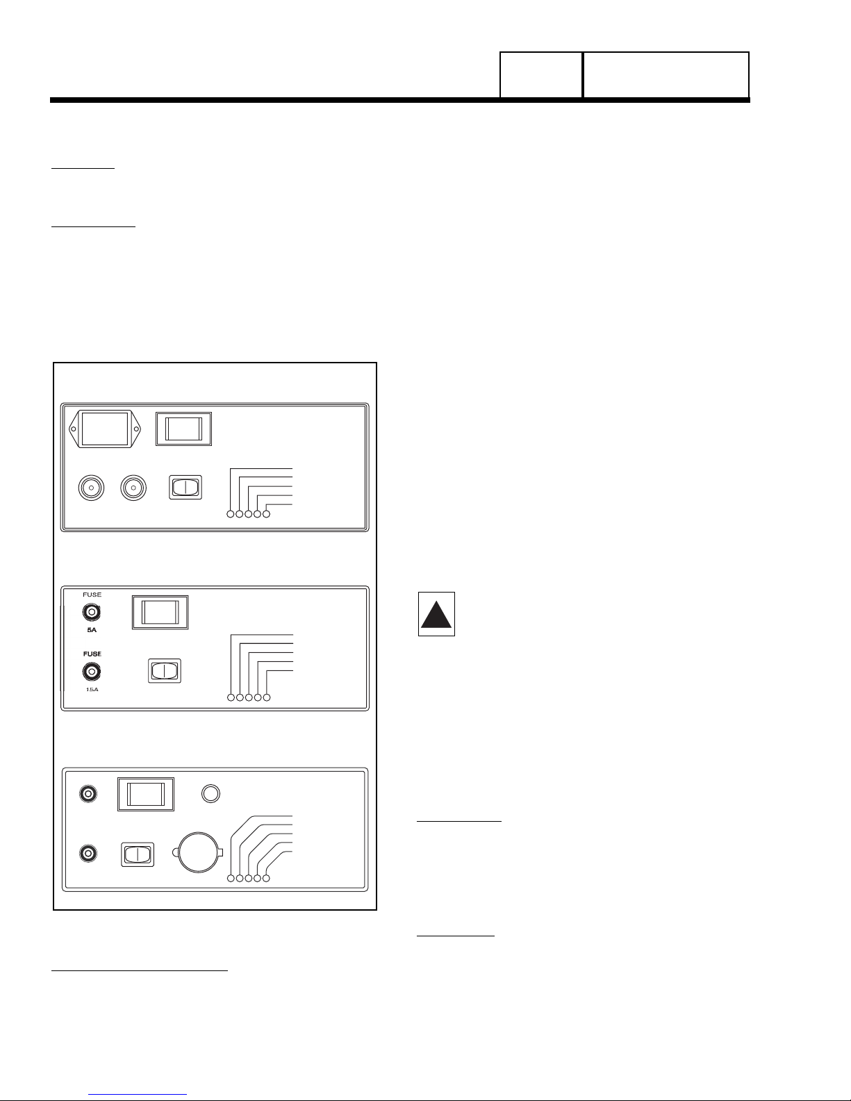
GENERAL:
See Figure 1 for appropriate control panel configura-
tions.
HOURMETER:
Equipped on some models only. The hourmeter indi-
cates engine-generator operating-time, in hours and
tenths of hours. Use the meter in conjunction with the
periodic maintenance schedule for the applicable
generator set. circuit board action turns the hourmeter
on at startup, via the same (Wire 14) circuit that powers the engine ignition system and the fuel shutoff
solenoid.
Figure 1. Control Panel
AUTO-OFF-MANUAL SWITCH:
Use this switch to (a) select fully automatic operation,
(b) to crank and start the engine manually, and (c) to
shut the unit down or to prevent automatic startup.
1. AUTO position:
a.Select AUTO for fully automatic operation.
b.When AUTO is selected, circuit board will moni-
tor utility power source voltage.
c. Should utility voltage drop below a preset level
and remain at such a low level for a preset time,
circuit board action will initiate engine cranking
and startup.
d.Following engine startup, circuit board action
will initiate transfer of electrical loads to the
“Standby” source side.
e.On restoration of utility source voltage above a
preset level, circuit board action will initiate
retransfer back to the “Utility Source” side.
f. Following retransfer, circuit board will shut the
engine down and will then continue to monitor
utility source voltage.
2. OFF Position:
a.Set the switch to OFF to stop an operating
engine.
b.To prevent an automatic startup from occurring,
set the switch to OFF.
3. MANUAL Position:
a.Set switch to MANUAL to crank and start unit
manually.
b.Engine will crank cyclically and start (same as
automatic startup, but without transfer). The unit
will transfer if utility voltage is not available.
DANGER: WHEN THE GENERATOR IS
INSTALLED IN CONJUNCTION WITH AN
AUTOMATIC TRANSFER SWITCH, ENGINE
CRANKING AND STARTUP CAN OCCUR AT
ANY TIME WITHOUT WARNING (PROVIDING
THE AUTO-OFF-MANUAL SWITCH IS SET TO
AUTO). TO PREVENT AUTOMATIC STARTUP
AND POSSIBLE INJURY THAT MIGHT BE
CAUSED BY SUCH STARTUP, ALWAYS SET
THE AUTO-OFF-MANUAL SWITCH TO ITS
OFF POSITION BEFORE WORKING ON OR
AROUND THIS EQUIPMENT.
15 AMP FUSE:
This fuse protects the DC control circuit (including the
circuit board) against overload. If the fuse element
has melted open due to an overload, engine cranking
or running will not be possible. Should fuse replacement become necessary, use only an identical 15
amp replacement fuse.
5 AMP FUSE:
Equipped on some models only. This fuse protects
the battery charge circuit against overload. If the fuse
element has melted open due to an overload, battery
charge will not occur. Should fuse replacement
become necessary, use only an identical 5 amp
replacement fuse.
!
OU
R
.
D
L
T
K
TFFAUTO
SE
C
S
S
=
SE
S=
T
PART 1
Page 20
GENERAL INFORMATION
SECTION 1.6
OPERATING INSTRUCTIONS
WITH HOURMETER
HOUR METER
FUSE
F
U
S
E
E
S
U
F
F
U
S
E
15A
FUSE
E
S
U
F
5A
AUTO
F
U
S
E
F
U
S
E
WITH
OFF MAN.
SET
EXERCISE
TIME
T HOURMETE
GENERAC
POWER SYSTEMS
SYSTEM SET
LOW OIL
HIGH TEMP
OVER SPEED
OVER CRANK
POWER SYSTEM
YSTEM SE
LOW OI
HIGH TEMP
VER SPEE
VER CRAN
HING GREEN LED
FLA
NO UTILITY SEN
4 FLASHING RED LED
EXERCISER NOT SE
E
EXERCI
ENERA
WITH 12 VDC ACCESSORY OUTLET
MAN.
ACCESSORY
OUTLET 7.5A MAX
12 VDC
EXTERNAL
GFCI
CIRCUIT
BREAKER
SYSTEM SET
LOW OIL
HIGH TEMP.
OVER SPEED
OVER CRANK
FLASHING GREEN LED =
NO UTILITY SENSE
4 FLASHING RED LEDS=
EXERCISER NOT SET
OUTLET FUSE
7.5A
SYSTEM FUSE
15A
AUTO
SET
EXERCISE
TIME
OFF
GENERAL INFORMATION
SECTION 1.6
OPERATING INSTRUCTIONS
PART 1
Page 21
THE SET EXERCISE SWITCH:
The air-cooled, prepackaged automatic standby gen-
erator will start and exercise once every seven (7)
days, on a day and at a time of day selected by the
owner or operator. The set exercise time switch is
provided to select the day and time of day for system
exercise.
See Section 5.1 (“The 7-Day Exercise Cycle”) for
instructions on how to set exercise time.
DANGER: THE GENERATOR WILL CRANK
AND START WHEN THE SET EXERCISE TIME
SWITCH IS SET TO “ON”. DO NOT ACTUATE
THE SWITCH TO “ON” UNTIL AFTER YOU
HAVE READ THE INSTRUCTIONS IN PART 5.
120 VAC GFCI OUTLET:
Some generator models are equipped with an exter-
nal, 15 amp, 120 volt, GFCI convenience outlet that is
located in the right rear of the generator enclosure.
When the generator is running, in the absence of utility power, this outlet may be used to power items outside the home such as lights or power tools. This outlet may also be used when utility power is present by
running the generator in MANUAL mode. This oultlet
does not provide power if the generator is not running. This outlet is protected by a 7.5 amp circuit
breaker located in the generator control panel.
(Figure 1).
7.5 AMP FUSE:
Equipped on some models only. This fuse protects
the 12 VDC accessory socket against overload. If the
fuse element has melted open due to an overload,
the 12 VDC socket will not provide power to accessories. Should fuse replacement become necessary,
use only an identical 7.5 amp replacement fuse.
PROTECTION SYSTEMS:
Unlike an automobile engine, the generator may have
to run for long periods of time with no operator present to monitor engine conditions. For that reason,
the engine is equipped with the following systems that
protect it against potentially damaging conditions:
• Low Oil Pressure Sensor
• High Temperature Sensor
• Overcrank
• Overspeed
There are LED readouts on the control panel to notify
you that one of these faults has occurred. There is
also a “System Set” LED that is lit when all of the following conditions are true:
1. The AUTO-OFF-MANUAL switch is set to the AUTO position.
2. The NOT IN AUTO dip switch is set to the OFF position
on the control board.
3. No alarms are present.
TO SELECT AUTOMATIC OPERATION
The following procedure applies only to those installations in which the air-cooled, prepackaged automatic
standby generator is installed in conjunction with a
prepackaged transfer switch. Prepackaged transfer
switches do not have an intelligence circuit of their
own. Automatic operation on prepackaged transfer
switch and generator combinations is controlled by
circuit board action.
To select automatic operation when a prepackaged
transfer switch is installed along with a prepackaged
home standby generator, proceed as follows:
1. Check that the prepackaged transfer switch main contacts are at their UTILITY position, i.e., the load is connected to the power supply. If necessary, manually actuate the switch main contacts to their UTILITY source
side. See Part 5 of this manual, as appropriate, for
instructions.
2. Check that utility source voltage is available to transfer
switch terminal lugs N1 and N2 (2-pole, 1-phase transfer switches).
3. Set the generator AUTO-OFF-MANUAL switch to its
AUTO position.
4. Actuate the generator main line circuit breaker to its “On”
or “Closed” position. With the preceding Steps 1 through
4 completed, a dropout in utility supply voltage below a
preset level will result in automatic generator cranking
and start-up. Following startup, the prepackaged transfer
switch will be actuated to its “Standby” source side, i.e.,
loads powered by the standby generator.
MANUAL TRANSFER TO “STANDBY” AND
MANUAL STARTUP
To transfer electrical loads to the “Standby” (generator) source and start the generator manually, proceed
as follows:
1. On the generator panel, set the AUTO-OFF-MANUAL
switch to OFF.
2. On the generator, set the main line circuit breaker to it’s
OFF or “Open” position.
3. Turn OFF the
power supply to the transfer switch, using whatever means
provided (such as a utility source line circuit breaker).
4. Manually actuate the transfer switch main contacts to
their “Standby” position, i.e., loads connected to the
“Standby” power source side.
NOTE: For instructions on manual operation of
prepackaged transfer switches, see Part 5.
5. On the generator panel, set the AUTO-OFF-MANUAL
switch to MANUAL. The engine should crank and start.
!

6. Let the engine warm up and stabilize for a minute or two
at no-load.
7. Set the generator main line circuit breaker to its “On” or
“Closed” position. The generator now powers the electrical loads.
MANUAL SHUTDOWN AND RETRANSFER
BACK TO “UTILITY”
To shut the generator down and retransfer electrical
loads back to the UTILITY position, proceed as follows:
1. Set the generator main line circuit breaker to its OFF or
“Open” position.
2. Let the generator run at no-load for a few minutes, to cool.
3. Set the generator AUTO-OFF-MANUAL switch to OFF.
Wait for the engine to come to a complete stop.
4. Turn off the utility power supply to the transfer switch
using whatever means provided (such as a utility source
main line circuit breaker)
5. Manually actuate the prepackaged transfer switch to its
UTILITY source side, i.e., load connected to the utility
source.
6. Turn on the utility power supply to the transfer switch,
using whatever means provided.
7. Set the generator AUTO-OFF-MANUAL switch to AUTO.
PART 1
GENERAL INFORMATION
SECTION 1.6
OPERATING INSTRUCTIONS
Page 22

Page 23
GENERAL INFORMATION
SECTION 1.7
AUTOMATIC OPERATING PARAMETERS
INTRODUCTION
When the prepackaged generator is installed in
conjunction with a prepackaged transfer switch,
either manual or automatic operation is possible.
Manual transfer and engine startup, as well as
manual shutdown and retransfer are covered in
Section 1.6. Selection of fully automatic operation is
also discussed in that section. This section will provide a step-by-step description of the sequence of
events that will occur during automatic operation of
the system.
AUTOMATIC OPERATING SEQUENCES
PHASE 1 - UTILITY VOLTAGE AVAILABLE:
With utility source voltage available to the transfer
switch, that source voltage is sensed by a circuit
board in the generator panel and the circuit board
takes no action.
Electrical loads are powered by the utility source and
the AUTO-OFF-MANUAL switch is set to AUTO.
PHASE 2 - UTILITY VOLTAGE DROPOUT:
If a dropout in utility source voltage should occur
below about 60 percent of the nominal utility source
voltage, a 15 second timer on the circuit board will
start timing. This timer is required to prevent false
generator starts that might be caused by transient utility voltage dips.
PHASE 3 - ENGINE CRANKING:
When the circuit board’s 15 second timer has finished
timing and if utility source voltage is still below 60 percent of the nominal source voltage, circuit board
action will energize a crank relay and a run relay.
Both of these relays are mounted on the circuit board.
If the engine starts, cranking will terminate when generator AC output frequency reaches approximately
30 Hz.
PHASE 4 - ENGINE STARTUP AND RUNNING:
The circuit board senses that the engine is running by
receiving a voltage/frequency signal from the engine
run windings.
When generator AC frequency reaches approximately 30 Hz, an engine warm-up timer on the circuit
board turns on. That timer will run for about ten (10)
seconds.
The engine warm-up timer lets the engine warm-up
and stabilize before transfer to the “Standby” source
can occur.
NOTE: The engine can be shut down manually at
any time, by setting the AUTO-OFF-MANUAL
switch to OFF.
PHASE 5 - TRANSFER TO “STANDBY”:
When the circuit board’s engine warm-up timer has
timed out and AC voltage has reached 50 percent of
the nominal rated voltage, circuit board action completes a transfer relay circuit to ground. The transfer
relay is housed in the prepackaged transfer switch
enclosure.
The transfer relay energizes and transfer of loads to
the “Standby” power source occurs. Loads are now
powered by standby generator AC output.
PHASE 6 - “UTILITY” POWER RESTORED:
When utility source voltage is restored above about
80 percent of the nominal supply voltage, a 15 second timer on the circuit board starts timing. If utility
voltage remains sufficiently high at the end of 15 seconds, retransfer can occur.
PHASE 7 - RETRANSFER BACK TO “UTILITY”:
At the end of the 15 second delay, circuit board action
will open a circuit to a transfer relay (housed in the
transfer switch). The transfer relay will then de-energize and retransfer back to the utility source will
occur. Loads are now powered by utility source
power. On retransfer, an engine cool-down timer
starts timing and will run for about one (1) minute.
PHASE 8 - GENERATOR SHUTDOWN:
When the engine cool-down timer has finished timing,
and if the minimum run timer has timed out, engine
shutdown will occur.
PART 1

PART 1
Page 24
GENERAL INFORMATION
SECTION 1.7
AUTOMATIC OPERATING PARAMETERS
AUTOMATIC OPERATING SEQUENCES CHART
SEQ. CONDITION ACTION SENSOR, TIMER OR OTHER
1 Utility source voltage is No action Voltage Dropout Sensor on circuit
available. circuit board.
2 Utility voltage dropout below A 15-second timer on circuit Voltage Dropout Sensor and 15
60% of rated voltage occurs. board turns on. second timer on circuit board.
3 Utility voltage is still below 15-second timer runs for 15 Voltage Dropout Sensor and 15
60% of rated voltage. seconds, then stops. second timer.
4 Utility voltage is still low after Circuit board action energizes a Circuit board crank and run
15 seconds. crank relay and a run relay. relays.
See NOTE 1.
5 Utility voltage still low and Circuit board’s “engine warmup Engine Warmup Timer (10 seconds)
the engine has started. timer” runs for 10 seconds.
6 Engine running and “engine Circuit board action energizes a Circuit board transfer relay circuit
warmup timer” times out. transfer relay in transfer switch T r a nsfer switch transfer relay.
AC output voltage above and transfer to “Standby” occurs.
50% nominal voltage.
7 Engine running and load is No further action Circuit board voltage pickup
powered by Standby power. sensor continues to seek an
acceptable “Utility” voltage.
8 Utility source voltage is Circuit board “voltage pickup Voltage Pickup Sensor (80%)
restored above 80% of rated sensor” reacts and a “re-transfer Return to Utility Timer (15 seconds)
time delay” turns on.
9 Utility voltage still high after 15 “Return to Utility Timer” times out Return to Utility Timer
seconds.
10 Utility voltage still high. Circuit board action opens the Circuit board transfer relay circuit
transfer relay circuit to ground. Transfer switch transfer relay.
Transfer relay de-energizes and
retransfer to “Utility” occurs.
11 Engine still running, loads are Circuit board “engine cooldown Circuit board Engine Cooldown
powered by Utility source. timer” starts running. Timer (1 minute)
12 After 1 minute, “engine cooldown Engine Cooldown Timer
timer” stops and circuit board’s Circuit board Run Relay.
run relay de-energizes. Engine
shuts down.
13 Engine is shut down, loads are No action. Voltage Dropout Sensor on circuit
powered by “Utility” source. circuit board.
Return to Sequence 1.

PART TITLE
2.1 Description and Components
2.2 Operational Analysis
2.3 Troubleshooting Flow Charts
2.4 Diagnostic Tests
PART 2
AC GENERATORS
Air-cooled, Prepackaged
Automatic Standby Generators
Models:
04389, 04758 (6 kW NG, 7 kW LP)
04456, 04759 (12 kW NG, 12 kW LP)
04390, 04760 (13 kW NG, 15 kW LP)
TABLE OF CONTENTS
Page 25
INTRODUCTION
The air-cooled, pre-packaged automatic standby system is an easy to install, fully enclosed and self-sufficient electric power system. It is designed especially
for homeowners, but may be used in other applications as well. On occurrence of a utility power failure,
this high performance system will (a) crank and start
automatically, and (b) automatically transfer electrical
loads to generator AC output.
The generator revolving field (rotor) is driven by an
air-cooled engine at about 3600 rpm.
The generator may be used to supply electrical power
for the operation of 120 and/or 240 volts, 1phase, 60
Hz, AC loads.
A 2-pole, “V-Type”, prepackaged transfer switch is
shipped with the unit (see Part 3). Prepackaged transfer switches do not include an “intelligence circuit” of
their own. Instead, automatic startup, transfer, running, retransfer and shutdown operations are controlled by a solid state circuit board in the generator
control panel.
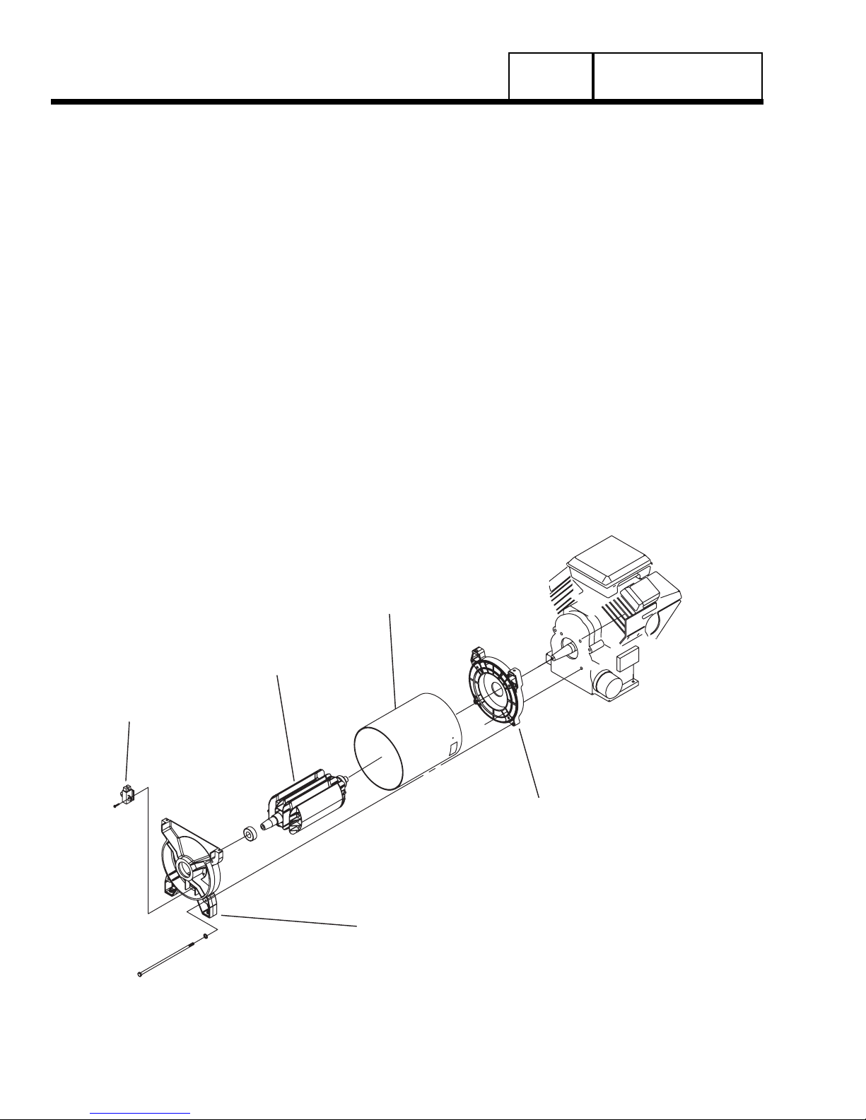
ENGINE-GENERATOR DRIVE SYSTEM
The generator revolving field is driven by an aircooled, horizontal crankshaft engine. The generator is
directly coupled to the engine crankshaft (see Figure
1), and mounted in an enclosure. Both the engine and
generator rotor are driven at approximately 3600 rpm,
to provide a 60 Hz AC output.
THE AC GENERATOR
Figure 1 shows the major components of the AC
generator.
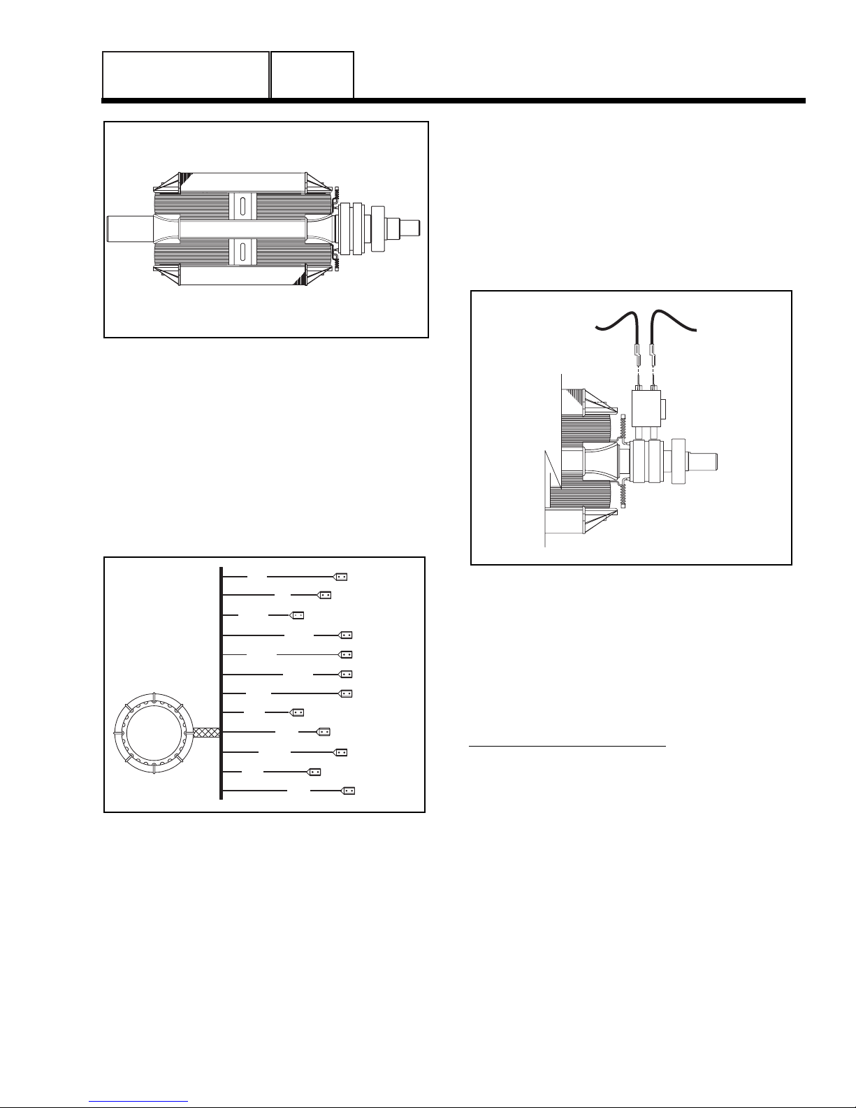
ROTOR ASSEMBLY
The 2-pole rotor must be operated at 3600 rpm to
supply a 60 Hertz AC frequency. The term “2-pole”
means the rotor has a single north magnetic pole and
a single south magnetic pole. As the rotor rotates, its
lines of magnetic flux cut across the stator assembly
windings and a voltage is induced into the stator
windings. The rotor shaft mounts a positive (+) and a
negative (-) slip ring, with the positive (+) slip ring
nearest the rear bearing carrier. The rotor bearing is
pressed onto the end of the rotor shaft. The tapered
rotor shaft is mounted to a tapered crankshaft and is
held in place with a single through bolt.
Figure 1. AC Generator Exploded View
PART 2
Page 26
AC GENERATORS
SECTION 2.1
DESCRIPTION & COMPONENTS
BRUSH HOLDER
ASSEMBLY
ROTOR
S TATO R
ENGINE
ENGINE
ADAPTOR
REAR BEARING
CARRIER
AC GENERATORS
SECTION 2.1
DESCRIPTION & COMPONENTS
PART 2
Page 27
Figure 2. The 2-Pole Rotor Assembly
STATOR ASSEMBLY
The stator can houses and retains (a) dual AC power
windings, (b) excitation winding, (c) battery charge
winding and (d) engine run winding. A total of twelve
(12) stator leads are brought out of the stator can as
shown in Figure 3.
The stator can is sandwiched between an engine
adapter and a rear bearing carrier. It is retained in
that position by four stator studs.
Figure 3 Stator Assembly Leads
BRUSH HOLDER AND BRUSHES
The brush holder is retained to the rear bearing carrier by means of two #10-32 x 9/16 Taptite screws. A
positive (+) and a negative (-) brush are retained in
the brush holder, with the positive (+) brush riding on
the slip ring nearest the rotor bearing.
Wire 4 connects to the positive (+) brush and Wire 0
to the negative (-) brush. Wire 0 connects to frame
ground. Rectified and regulated excitation current, as
well as current from a field boost circuit, are delivered
to the rotor windings via Wire 4, and the positive (+)
brush and slip ring. The excitation and field boost current passes through the windings and to frame
ground via the negative (-) slip ring and brush, and
Wire 0. This current flow creates a magnetic field
around the rotor having a flux concentration that is
proportional to the amount of current flow.
Figure 4. Brush Holder and Brushes
OTHER AC GENERATOR COMPONENTS
Some AC generator components are housed in the
generator control panel enclosure, and are not shown
in Figure 1. These are (a) an excitation circuit breaker, (b) a voltage regulator, and (c) a main line circuit
breaker.
EXCITATION CIRCUIT BREAKER:
The excitation circuit breaker (CB2) is housed in the
generator panel enclosure and electrically connected
in series with the excitation (DPE) winding output to
the voltage regulator. The breaker is self-resetting,
i.e.; its contacts will close again when excitation current drops to a safe value.
If the circuit breaker has failed open, excitation current
flow to the voltage regulator and, subsequently, to the
rotor windings will be lost. Without excitation current
flow, AC voltage induced into the stator AC power
windings will drop to a value that is commensurate
with the rotor residual magnetism (see Figure 5).
2
6
11P
11S
22P
22S
33
44
55
66A
66
77
0
4
- +
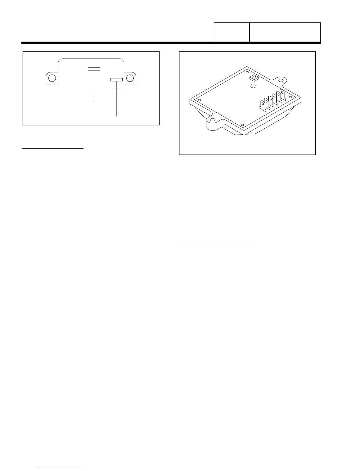
Figure 5. Excitation Circuit Breaker
VOLTAGE REGULATOR:
A typical voltage regulator is shown in Figure 6.
Unregulated AC output from the stator excitation
winding is delivered to the regulator’s DPE terminals,
via Wire 2, the excitation circuit breaker, Wire 162,
and Wire 6. The voltage regulator rectifies that current
and, based on stator AC power winding sensing, regulates it. The rectified and regulated excitation current
is then delivered to the rotor windings from the positive (+) and negative (-) regulator terminals, via Wire
4 and Wire 1. Stator AC power winding “sensing” is
delivered to the regulator “SEN” terminals via Wires
11 and 22.
The regulator provides “over-voltage” protection, but
does not protect against “under-voltage”. On occurrence of an “over-voltage” condition, the regulator will
“shut down” and complete loss Of excitation current to
the rotor will occur. Without excitation current, the
generator AC output voltage will drop to approximately one-half (or lower) of the unit’s rated voltage.
Figure 6. Typical Voltage Regulator
A single red lamp (LED) glows during normal operation. The lamp will become dim if excitation winding
AC output diminishes. It will go out on occurrence of
an open condition in the sensing AC output circuit.
An adjustment potentiometer permits the stator AC
power winding voltage to be adjusted. Perform this
adjustment with the generator running at no-load, and
with a 62 Hz AC frequency (62 Hz equals 3720 rpm).
At the stated no-load frequency, adjust to obtain a
line-to-line AC voltage of about 252 volts.
MAIN LINE CIRCUIT BREAKER:
The main line circuit breaker protects the generator
against electrical overload. See “Specifications” in
front of manual for amp ratings.
62
PART 2
Page 28
AC GENERATORS
SECTION 2.1
DESCRIPTION & COMPONENTS
1
 Loading...