

Guardian 4721, 4722, 4723, 4724, 4725 Repair Manual
...
Models: 4721, 4722, 4723, 4724, 4725, 4726
1.5L HOME STANDBY GENERATORS
www.guardiangenerators.com
LIQUID-COOLED
DIAGNOSTIC
REPAIR MANUAL
Page ii
Study these SAFETY RULES carefully before installing, operating or servicing this equipment. Become familiar with the Owner’s Manual and with the unit. The generator can operate safely, efficiently and reliably only
if it is properly installed, operated and maintained. Many accidents are caused by failing to follow simple and
fundamental rules or precautions.
Generac cannot anticipate every possible circumstance that might involve a hazard. The warnings in this
manual, and on tags and decals affixed to the unit are, therefore, not all-inclusive. If using a procedure,
work method or operating technique that Generac does not specifically recommend, ensure that it is safe
for others. Also make sure the procedure, work method or operating technique utilized does not render
the generator unsafe.
Despite the safe design of this generator, operating this equipment imprudently, neglecting its maintenance or being careless can cause possible injury or death. Permit only responsible and capable
persons to install, operate or maintain this equipment.
Potentially lethal voltages are generated by these machines. Ensure all steps are taken to render the
machine safe before attempting to work on the generator.
Parts of the generator are rotating and/or hot during operation. Exercise care near running generators.
!
SAVE THESE INSTRUCTIONS – The manufacturer suggests that these rules for safe operation be copied and posted in potential hazard areas. Safety should be stressed to all operators and potential operators of this equipment.
!
Important Safety Notice
Proper service and repair is important to the safe, economical and reliable operation of all
standby electric power systems. The troubleshooting, testing and servicing procedures recommended by Generac and described in this manual are effective methods of performing such
operations. Some of these operations or procedures may require the use of specialized equipment. Such equipment should be used when and as recommended.
It is important to note that this manual contains various DANGER, CAUTION, and NOTE blocks.
These should be read carefully in order to minimize the risk of personal injury or to prevent
improper methods or practices from being used. Use of improper or unauthorized practices
may damage equipment or render it unsafe. The DANGER, CAUTION and NOTE blocks are not
exhaustive. Generac could not possibly know, evaluate and advise the service trade of all conceivable ways in which operations described in this manual might be accomplished or of the
possible hazardous consequences of each way. Consequently, Generac has not taken any such
broad evaluation. Accordingly, anyone who uses any troubleshooting, testing or service procedure that is not recommended by Generac must first satisfy himself that neither his safety nor
the equipment's safety will be jeopardized by the procedure or the method he selects.
!
DANGER

Page iii
GENERAL HAZARDS
• For safety reasons, Generac recommends that this equipment be installed, serviced and repaired by an
authorized service dealer or other competent, qualified electrician or installation technician who is
familiar with applicable codes, standards and regulations. The operator also must comply with all
such codes, standards and regulations.
• Installation, operation, servicing and repair of this (and related) equipment must always comply with
applicable codes, standards, laws and regulations. Adhere strictly to local, state and national electrical
and building codes. Comply with regulations the Occupational Safety and Health Administration
(OSHA) has established. Also, ensure that the generator is installed, operated and serviced in accordance with the manufacturer’s instructions and recommendations. Following installation, do nothing
that might render the unit unsafe or in noncompliance with the aforementioned codes, standards, laws
and regulations.
• The engine exhaust fumes contain carbon monoxide gas, which can be DEADLY. This dangerous gas, if
breathed in sufficient concentrations, can cause unconsciousness or even death. For that reason, adequate ventilation must be provided. Exhaust gases must be piped safely away from any building or
enclosure that houses the generator to an area where people, animals, etc., will not be harmed. This
exhaust system must be installed properly, in strict compliance with applicable codes and standards.
• Keep hands, feet, clothing, etc., away from drive belts, fans, and other moving or hot parts. Never
remove any drive belt or fan guard while the unit is operating.
• Adequate, unobstructed flow of cooling and ventilating air is critical to prevent buildup of explosive
gases and to ensure correct generator operation. Do not alter the installation or permit even partial
blockage of ventilation provisions, as this can seriously affect safe operation of the generator.
• Keep the area around the generator clean and uncluttered. Remove any materials that could become
hazardous.
• When working on this equipment, remain alert at all times. Never work on the equipment when physically or mentally fatigued.
• Inspect the generator regularly, and promptly repair or replace all worn, damaged or defective parts
using only factory-approved parts.
• Before performing any maintenance on the generator, disconnect its battery cables to prevent accidental start-up. Disconnect the cable from the battery post indicated by a NEGATIVE, NEG or (–) first.
Reconnect that cable last.
• Never use the generator or any of its parts as a step. Stepping on the unit can stress and break parts,
and may result in dangerous operating conditions from leaking exhaust gases, fuel leakage, oil leakage,
etc.
ELE
CTRICAL HAZARDS
• All generators covered by this manual produce dangerous electrical voltages and can cause fatal electrical shock. Utility power delivers extremely high and dangerous voltages to the transfer switch as well as
the standby generator. Avoid contact with bare wires, terminals, connections, etc., on the generator as
well as the transfer switch, if applicable. Ensure all appropriate covers, guards and barriers are in place
before operating the generator. If work must be done around an operating unit, stand on an insulated,
dry surface to reduce shock hazard.
• Do not handle any kind of electrical device while standing in water, while barefoot, or while hands or
feet are wet. DANGEROUS ELECTRICAL SHOCK MAY RESULT.
• If people must stand on metal or concrete while installing, operating, servicing, adjusting or repairing
this equipment, place insulative mats over a dry wooden platform. Work on the equipment only while
standing on such insulative mats.
!!

Page iv
• The National Electrical Code (NEC), Article 250 requires the frame and external electrically conductive
parts of the generator to be connected to an approved earth ground and/or grounding rods. This
grounding will help prevent dangerous electrical shock that might be caused by a ground fault condition in the generator set or by static electricity. Never disconnect the ground wire.
• Wire gauge sizes of electrical wiring, cables and cord sets must be adequate to handle the maximum
electrical current (ampacity) to which they will be subjected.
• Before installing or servicing this (and related) equipment, make sure that all power voltage supplies
are positively turned off at their source. Failure to do so will result in hazardous and possibly fatal
electrical shock.
• Connecting this unit to an electrical system normally supplied by an electric utility shall be by means of
a transfer switch so as to isolate the generator electric system from the electric utility distribution system when the generator is operating. Failure to isolate the two electric system power sources from each
other by such means will result in damage to the generator and may also result in injury or death to
utility power workers due to backfeed of electrical energy.
• Generators installed with an automatic transfer switch will crank and start automatically when NORMAL (UTILITY) source voltage is removed or is below an acceptable preset level. To prevent such automatic start-up and possible injury to personnel, disable the generator’s automatic start circuit (battery
cables, etc.) before working on or around the unit. Then, place a “Do Not Operate” tag on the generator
control panel and on the transfer switch.
• In case of accident caused by electric shock, immediately shut down the source of electrical power. If
this is not possible, attempt to free the victim from the live conductor. AVOID DIRECT CONTACT
WITH THE VICTIM. Use a nonconducting implement, such as a dry rope or board, to free the victim
from the live conductor. If the victim is unconscious, apply first aid and get immediate medical help.
• Never wear jewelry when working on this equipment. Jewelry can conduct electricity resulting in electric shock, or may get caught in moving components causing injury.
FIRE HAZARDS
• Keep a fire extinguisher near the generator at all times. Do NOT use any carbon tetra-chloride type
extinguisher. Its fumes are toxic, and the liquid can deteriorate wiring insulation. Keep the extinguisher
properly charged and be familiar with its use. If there are any questions pertaining to fire extinguishers, consult the local fire department.
EXPLOSION HAZARDS
• Properly ventilate any room or building housing the generator to prevent build-up of explosive gas.
• Do not smoke around the generator. Wipe up any fuel or oil spills immediately. Ensure that no combustible materials are left in the generator compartment, or on or near the generator, as FIRE or
EXPLOSION may result. Keep the area surrounding the generator clean and free from debris.
• Generac generator sets may operate using one of several types of fuels. All fuel types are potentially
FLAMMABLE and/or EXPLOSIVE and should be handled with care. Comply with all laws regulating
the storage and handling of fuels. Inspect the unit’s fuel system frequently and correct any leaks immediately. Fuel supply lines must be properly installed, purged and leak tested according to applicable
fuel-gas codes before placing this equipment into service.
• Diesel fuels are highly FLAMMABLE. Gaseous fluids such as natural gas and liquid propane (LP) gas
are extremely EXPLOSIVE. Natural gas is lighter than air, and LP gas is heavier than air; install leak
detectors accordingly.

Page 1
PART TITLE PAGE
SPECIFICATIONS 2
1 General Information 3
2 Prepackaged Liquid Cooled AC Generators 19
3 V-Type Prepackaged Transfer Switches 39
4 DC Control- Units with Liquid-Cooled Engine 57
5 Operational Tests and Adjustments 95
6 Electrical Data 101
TABLE OF CONTENTS
1.5 LITER PREPACKAGED
HOME STANDBY
GENERATORS
DIAGNOSTIC
REPAIR MANUAL
Page 2
GENERATOR SPECIFICATIONS
Phase ............................................................ Single
Rated Max. Cont. AC Power Output (kW) ......... 15*
Rated Voltage (volts) ................................. 120/240
No. of Rotor Poles - 15 kW ................................... 2
No. of Rotor Poles - 20/25 kW .............................. 4
Driven Speed of Rotor - 15 kW ....................... 1800
Driven Speed of Rotor - 20/25 kW .................. 3600
Rotor Excitation System .. Direct excited brush type
Rotor/Stator Insulation ................................ Class F
* Rated power of generator is subject to and limited
by such factors as ambient temperature, altitude,
engine condition, and other factors. Engine power
will decrease about 3% for each 1000 feet above
600 feet and will decrease an additional 1.65% for
each 10°F above 77°F. Maximum output power of
the generator is limited by maximum engine power.
ENGINE SPECIFICATIONS
Make .........................................................Mitsubishi
Displacement.............................................92 inches
(1.5 liters)
Cylinder Arrangement .................................4, in-line
Valve Arrangement...........................Overhead Cam
Firing Order ...................................................1-3-4-2
Number of Main Bearings .......................................5
Compression Ratio ..........................................9 to 1
No. of Teeth on Flywheel....................................104
Ignition Timing
at 1800 rpm..................................35 degrees BTDC
Spark Plug Gap..............................0.020-0.025 inch
Recommended Spark Plugs
Champion .................................................RN11YC4
Oil Pressure ...............................................30-50 psi
Crankcase Oil Capacity ...3.0 U.S. quarts (2.8 liters)
Recommended Engine Oil ...................SAE 15W-40
Type of Cooling SystemPressurized, closed recovery
Cooling Fan ..........................................Pusher Type
Cooling System Capacity ..2 U.S. gallons (7.6 liters)
Recommended Coolant........Use a 50-50 mixture of
ethylene glycol base.
FUEL CONSUMPTION
25 kW Models
Using Natural Gas .................... 441 cu. ft. per hour
Using LP Gas.......... 175 cubic ft. (4.8 gal.) per hour
20 kW Models
Using Natural Gas .................... 359 cu. ft. per hour
Using LP Gas ......... 143 cubic ft. (4.0 gal.) per hour
15 kW Models
Using Natural Gas .................... 277 cu. ft. per hour
Using LP Gas .......... 110 cubic ft.(3.1 gal.) per hour
NOTE: Fuel consumption is given at rated maximum continuous power output when using natural
gas rated at 1000 Btu per cubic foot and LP gas
rated 2520 Btu per cubic foot. Actual fuel con-
sumption obtained may vary depending on such
variables as applied load, ambient temperature,
engine conditions and other environmental factors.
Fuel pressure for a natural gas set up should be five
inches to 14 inches of water column (0.18 to 0.5 psi)
at all load ranges.
Fuel pressure for an LP vapor set up should be 11
inches to 14 inches of water column (0.4 to 0.5 psi) at
all load ranges.
ENGINE OIL RECOMMENDATIONS
The unit has been filled with 15W-40 engine oil at the
factory. Use a high-quality detergent oil classified “For
Service SJ or latest available.” Detergent oils keep
the engine cleaner and reduce carbon deposits. Use
oil having the following SAE viscosity rating, based on
the ambient temperature range anticipated before the
next oil change:
NOTE: Synthetic oil is highly recommended when
the generator will be operating in ambient temperatures which regularly exceed 90° F and/or fall
below 30° F.
ANY ATTEMPT TO CRANK OR START THE
ENGINE BEFORE IT HAS BEEN PROPERLY
SERVICED WITH THE RECOMMENDED OIL
MAY RESULT IN AN ENGINE FAILURE.
COOLANT RECOMMENDATIONS
Use a mixture of half low silicate ethylene glycol base
anti-freeze and deionized water. Cooling system
capacity is about 8 U.S. quarts (7.6 liters). Use only
deionized water and only low silicate anti-freeze. If
desired, add a high quality rust inhibitor to the recommended coolant mixture. When adding coolant,
always add the recommended 50-50 mixture.
DO NOT USE ANY CHROMATE BASE RUST
INHIBITOR WITH ETHYLENE GLYCOL BASE
ANTI-FREEZE OR CHROMIUMHYDROXIDE
(“GREEN SLIME”) FORMS AND WILL CAUSE
OVERHEATING. ENGINES THAT HAVE BEEN
OPERATED WITH A CHROMATE BASE RUST
INHIBITOR MUST BE CHEMICALLY CLEANED
BEFORE ADDING ETHYLENE GLYCOL BASE
ANTI-FREEZE. USING ANY HIGH SILICATE
ANTI-FREEZE BOOSTERS OR ADDITIVES WILL
ALSO CAUSE OVERHEATING. IT IS ALSO RECOMMENDED THAT ANY SOLUBLE OIL
INHIBITOR IS NOT USED FOR THIS EQUIPMENT.
!
!
SPECIFICATIONS
Temperature Oil Grade (Recommended)
Above 80° F (27° C) SAE 30W or 15W-40
32° to 80° F (-1° to 27° C) SAE 20W-20 or 15W-40
Below 32° F (0° C) SAE 10W or 15W-40

Page 3
PART TITLE PAGE
1.1 Generator Identification 4
1.2 Prepackaged Installation Basics 6
1.3 Preparation Before Use 9
1.4 Testing, Cleaning and Drying 10
1.5 Engine-Generator Protective Devices 13
1.6 Operating Instructions 15
1.7 Automatic Operating Parameters 17
TABLE OF CONTENTS
1.5 LITER PREPACKAGED
HOME STANDBY
GENERATORS
PART 1
GENERAL
INFORMATION
PART 1
GENERAL INFORMATION
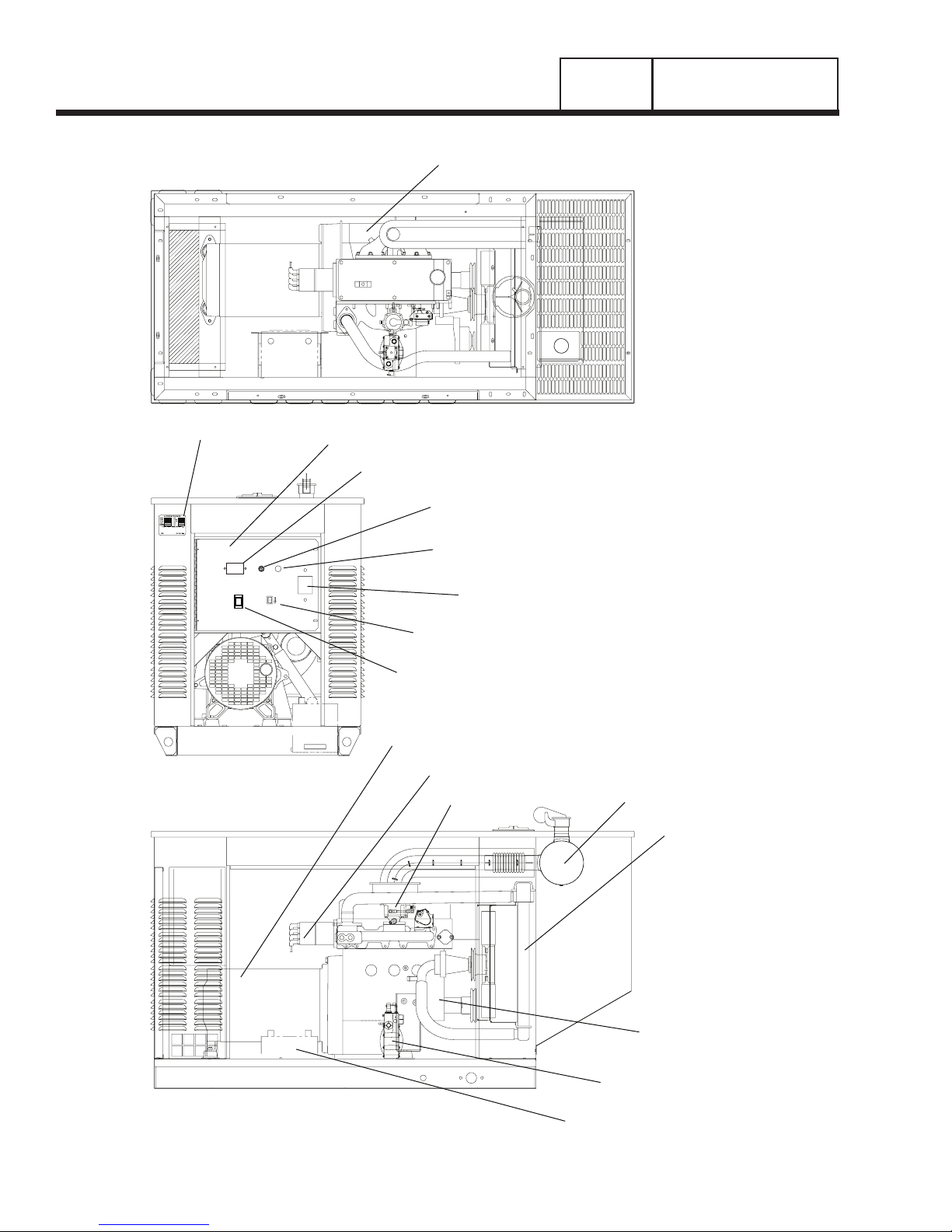
SECTION 1.1
GENERATOR IDENTIFICATION
Page 4
STARTER
DATA PLATE
FUSE
FAULT
15-A
INDICATOR
HOURMETER
AGC
AUTO
SET
EXERCISE
TIME
OFF
ON
MANUAL
CONTROL PANEL
HOURMETER
15 AMP FUSE
FAULT INDICATOR
SET EXERCISE SWITCH
AUTO-OFF-MANUAL SWITCH
ALTERNATOR
DISTRIBUTOR
CIRCUIT BREAKER
CARBURETOR
MUFFLER
RADIATOR
ENGINE
FUEL REGULATOR
BATTERY
PART 1
GENERAL INFORMATION
SECTION 1.1
GENERATOR IDENTIFICATION
INTRODUCTION
This Diagnostic Repair Manual has been prepared
especially for the purpose of familiarizing service personnel with the testing, troubleshooting and repair of
prepackaged home standby generator systems.
Every effort has been expended to ensure that information and instructions in the manual are both accurate and current. However, the manufacturer reserves
the right to change, after or otherwise improve the
product at any time without prior notification.
The manual has been divided into several PARTS.
Each PART has been divided into SECTIONS. Each
SECTION consists of two or more SUBSECTIONS.
It is not the manufacturers intent to provide detailed
disassembly and reassembly instructions in this manual. It is the manufacturers intent to (a) provide the
service technician with an understanding of how the
various assemblies and systems work, (b) assist the
technician in finding the cause of malfunctions, and
(c) effect the expeditious repair of the equipment.
UNITS WITH LIQUID COOLED ENGINE
A typical prepackaged generator with liquid cooled
engine is shown on Page 4 at front of this manual.
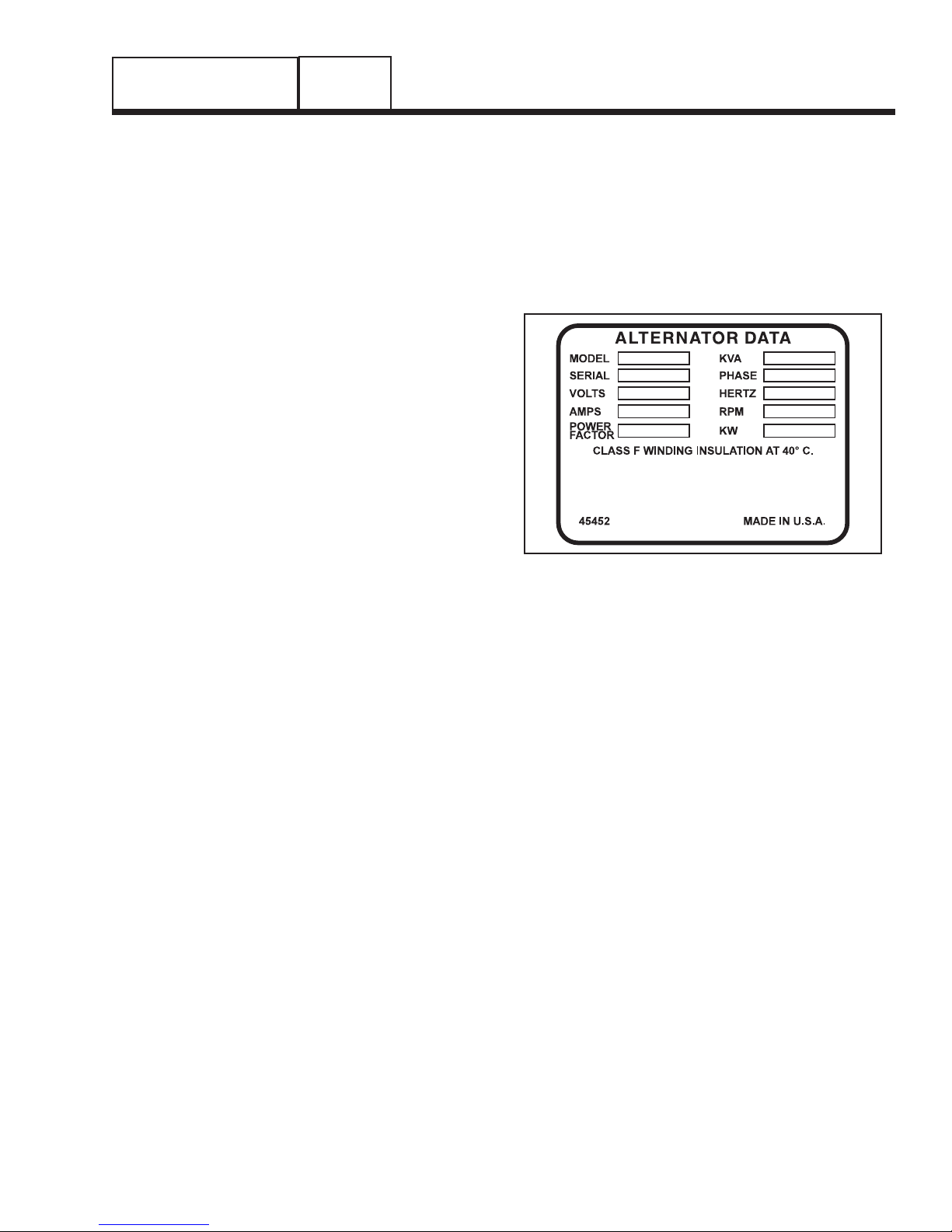
A DATA PLATE, affixed to the unit, contains important information pertaining to the unit, including its
Model Number, Serial Number, kW rating, rated rpm,
rated voltage, etc. The information from this data
plate may be required when requesting information,
ordering parts, etc.
Figure 1. A Typical Data Plate
Page 5
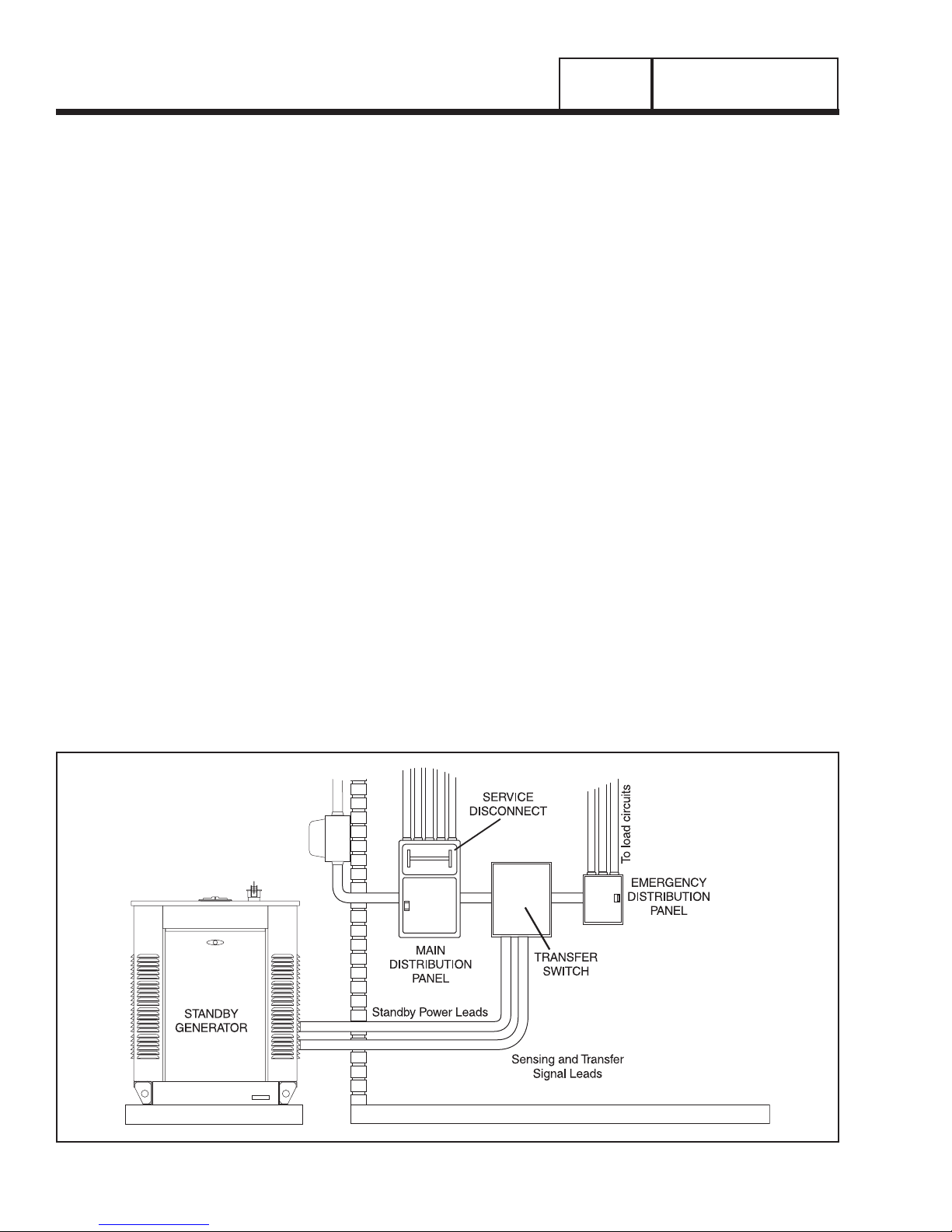
INTRODUCTION
Information in this section is provided so that the service technician will have a basic knowledge of installation requirements for prepackaged home standby
systems. Problems that arise are often related to poor
or unauthorized installation practices.
A typical prepackaged home standby electric system
is shown in Figure 1, below. Installation of such a system includes the following:
• Selecting a Location
• Mounting of the generator.
• Grounding the generator.
• Providing a fuel supply.
• Mounting the transfer switch.
• Connecting power source and load lines.
• Connecting system control wiring.
• Post installation tests and adjustments.
SELECTING A LOCATION
Install the generator set as close as possible to the
electrical load distribution panel(s) that will be powered
by the unit, ensuring that there is proper ventilation for
cooling air and exhaust gases. This will reduce wiring
and conduit lengths. Wiring and conduit not only add to
the cost of the installation, but excessively long wiring
runs can result in a voltage drop.
MOUNTING THE GENERATOR
Mount the generator set to a concrete slab. The slab
should extend past the generator and to a distance of at
least twelve (12) inches on all sides. The unit can be
retained to the concrete slab with masonry anchor bolts.
GROUNDING THE GENERATOR
The National Electric Code requires that the frame
and external electrically conductive parts of the generator be property connected to an approved earth
ground. Local electrical codes may also require proper grounding of the unit. For that purpose, a grounding lug is attached to the unit. Grounding may be
accomplished by attaching a stranded copper wire of
the proper size to the generator’s grounding lug and
to an earth-driven copper or brass grounding-rod
(electrode). Consult with a local electrician for grounding requirements in your area.
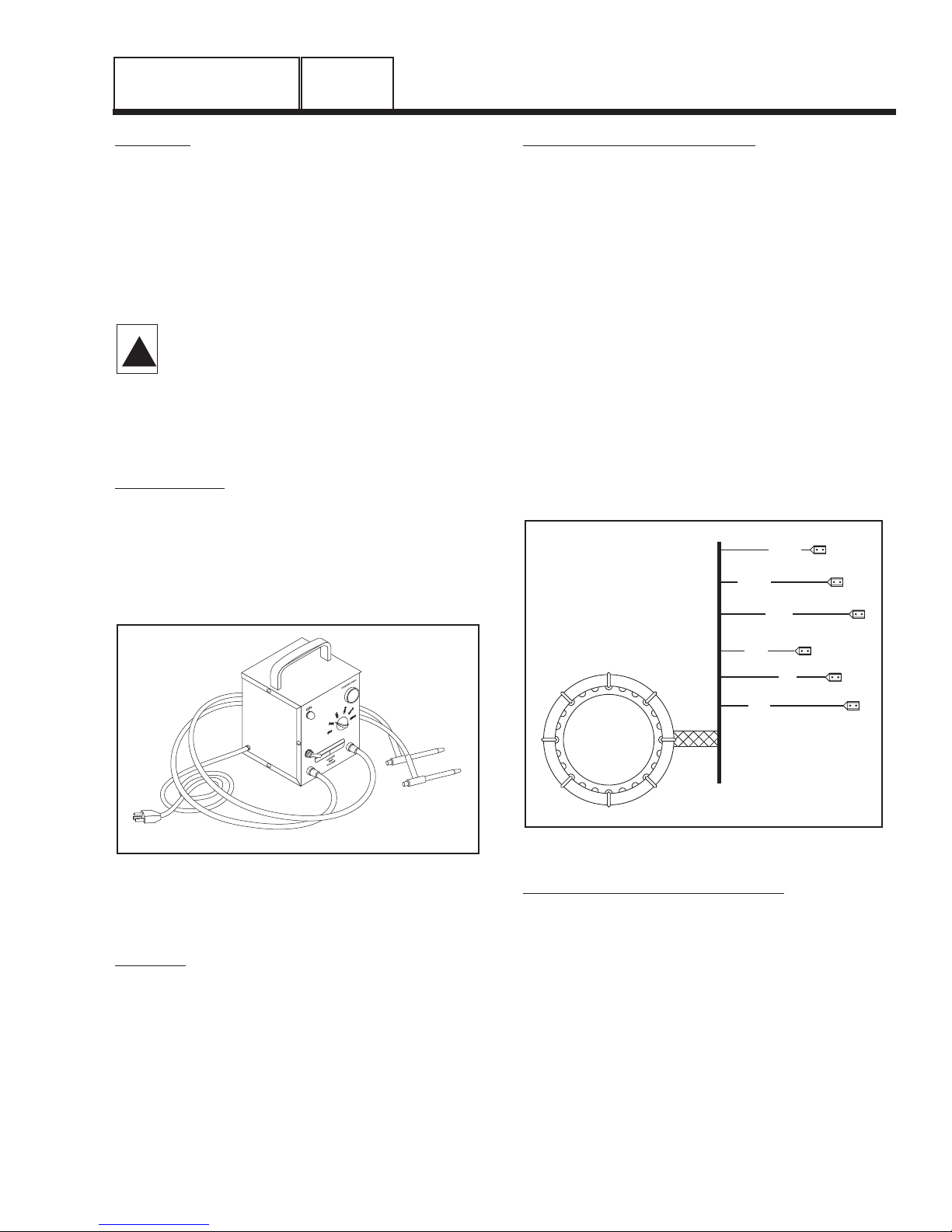
THE FUEL SUPPLY
Units with liquid cooled engines are shipped from the
factory to run on natural gas (Figure 2). Units that will
use LP (propane) gas fuel (Figure 3) must be converted in the field per instructions located in the
Installation Manual.
LP (propane) gas is usually supplied as a liquid in
pressure tanks. Liquid cooled units require a "vapor
withdrawal" type of fuel supply system when LP
(propane) gas is used. The vapor withdrawal system
utilizes the gaseous fuel vapors that form at the top of
the supply tank.
The pressure at which LP gas is delivered to the generator’s fuel solenoid valve may vary considerably,
depending on ambient temperatures. In cold weather,
supply pressures may drop to "zero". In warm weather, extremely high gas pressures may be encountered. A primary/secondary supply regulator is
required to maintain correct gas supply pressure to
the generator demand regulator.
Minimum recommended gaseous fuel pressure at
the inlet side of the generator’s fuel solenoid valve is
Figure 1. Typical Prepackaged Installation
PART 1
Page 6
GENERAL INFORMATION
SECTION 1.2
PREPACKAGED INSTALLATION BASICS
GENERAL INFORMATION
SECTION 1.2
PREPACKAGED INSTALLATION BASICS
PART 1
Page 7
11 inches water column for LP gas (6.38 ounces per
square inch), and 5 inches water column for natural
gas (2.89 ounces per square inch). The maximum
recommended pressure is 14 inches water column
(8.09 ounces per square inch). A primary regulator
may be required to ensure that proper fuel supply
pressures are maintained.
DANGER: LP AND NATURAL GAS ARE
BOTH HIGHLY EXPLOSIVE. GASEOUS FUEL
LINES MUST BE PROPERLY PURGED AND
TESTED FOR LEAKS BEFORE THIS EQUIPMENT IS PLACED INTO SERVICE AND PERIODICALLY THEREAFTER. PROCEDURES
USED IN GASEOUS FUEL LEAKAGE TESTS
MUST COMPLY STRICTLY WITH APPLICA-
BLE FUEL GAS CODES. DO NOT USE
FLAME OR ANY SOURCE OF HEAT TO TEST
FOR GAS LEAKS. NO GAS LEAKAGE IS
PERMITTED. LP GAS IS HEAVIER THAN AIR
AND TENDS TO SETTLE IN LOW AREAS.
NATURAL GAS IS LIGHTER THAN AIR AND
TENDS TO SETTLE IN HIGH PLACES. EVEN
THE SLIGHTEST SPARK CAN IGNITE THESE
FUELS AND CAUSE AN EXPLOSION.
Use of a flexible length of hose between the generator fuel line connection and rigid fuel lines is required.
This will help prevent line breakage that might be
caused by vibration or if the generator shifts or settles. The flexible fuel line must be approved for use
with gaseous fuels.
!
Figure 3. Typical LP Gas Fuel System (Liquid Cooled Units)
Figure 2. Typical Natural Gas Fuel System (Liquid Cooled Units)
5-14 INCHES WATER COLUMN OPTIMUM
APPROVED FLEX LINE
(CAUTION! — KEEP FLEX FUEL LINE STRAIGHT)
NATURAL GAS
PRIMARY
REGULATOR
GAS CARBURETOR
GENERATOR
DEMAND
REGULATOR
LP PRIMARY/SECONDARY
SUPPLY REGULATOR
VAPOR
LIQUID
GENERATOR BASE
MANUAL SHUTOFF VALVE
APPROVED FLEX LINE
(CAUTION! — KEEP FLEX FUEL LINE STRAIGHT)
11-14 INCHES WATER
COLUMN OPTIMUM
GENERATOR BASE
GAS CARBURETOR
GENERATOR
DEMAND
REGULATOR
MANUAL SHUTOFF VALVE
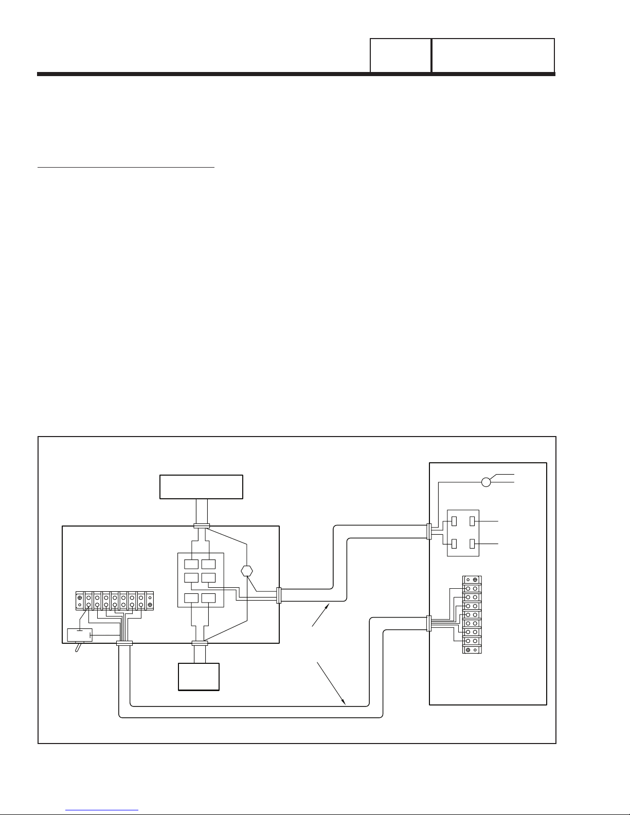
THE TRANSFER SWITCH
A transfer switch is required by electrical code, to prevent electrical feedback between the utility and standby power sources, and to transfer electrical loads
from one power supply to another safely.
PREPACKAGED TRANSFER SWITCHES:
Instructions and information on prepackaged transfer
switches may be found in Part 3 of this manual.
POWER SOURCE AND LOAD LINES
The utility power supply lines, the standby (generator)
supply lines, and electrical load lines must all be connected to the proper terminal lugs in the transfer
switch. The following rules apply:
In 1-phase systems with a 2-pole transfer switch, connect the two "Utility" source hot lines to transfer
switch Terminal Lugs N1 and N2. Connect the
"Standby" source hot lines (E1, E2) to transfer switch
Terminal Lugs E1 and E2. Connect the load lines
from transfer switch Terminal Lugs T1/T2 to the electrical load circuit. Connect "Utility", "Standby" and
"Load" neutral lines to the neutral block in the transfer
switch.
SYSTEM CONTROL INTERCONNECTIONS
Prepackaged home standby generators are equipped
with a terminal board identified with the following ter-
minals: (a) utility 1, (b) utility 2, (c) load 1, (d) load 2,
(e) 23, and (f) 194. Prepackaged transfer switches
house an identically marked terminal board. Suitable,
approved wiring must be interconnected between
identically numbered terminals in the generator and
transfer switch. When these six terminals are properly
interconnected, dropout of utility source voltage below
a preset value will result in automatic generator startup and transfer of electrical loads to the "Standby"
source. On restoration of utility source voltage above a
preset value will result in retransfer back to that source
and generator shutdown. System control wiring must
be routed through its own separate conduit.
A control board, mounted on the standby generator
set, provides a "7-day exercise" feature. This feature
allows the standby generator to start and run once
every 7 days, on a day and at a time of day selected.
The timer clock that controls this automatic exercise
of the unit must be powered by voltage from the
transfer switch Load 1/Load 2 terminals. If the exercise function is to be made available, connect suitable
wiring from the ATS transfer switch load terminal lugs,
to the "Load 1/Load 2" terminals in the generator.
The control board in the generator also provides a
battery "trickle charge" circuit. This circuit, when powered by utility source voltage, will deliver a charging
voltage to the battery during non-operating periods to
keep the battery charged. To use the trickle charge
feature, connect suitable wiring to the generator’s
"Utility 1/Utility 2" terminals and to the appropriate terminals in the "ATS" transfer switch.
PART 1
Page 8
GENERAL INFORMATION
SECTION 1.2
PREPACKAGED INSTALLATION BASICS
Figure 4. Prepackaged Interconnection Diagram
TRANSFER
SWITCH
UTILITY 1
REMOTE TEST
SWITCH (OPTIONAL)
- OPEN SWITCH TO TEST -
SWITCH TYPE, SPST
ELECTRICAL RATINGS,
2A @ 250Vac MIN.
LOAD 1
LOAD 2
UTILITY 2
22
UTILITY SUPPLY WITH
SERVICE DISCONNECT
NEUTRAL
N1 N2
23
194
E1 E2
T1 T2
CUSTOMER
LOAD
LUG
NOTE:
POWER LEADS AND
TRANSFER SWITCH
LEADS MUST BE
RUN IN TWO
DIFFERENT CONDUITS.
NEUTRAL
CONNECTION
CB1
AC GENERATOR
CONTROL PANEL
33
11
44
UTILITY 1 (N1)
UTILITY 2 (N2)
LOAD 1 (T1)
LOAD 2 (T2)
23
194
GENERAL INFORMATION
SECTION 1.3
PREPARATION BEFORE USE
PART 1
Page 9
GENERAL
The installer must ensure that the home standby generator has been properly installed. The system must
be inspected carefully following installation. All applicable codes, standards and regulations pertaining to
such installations must be strictly complied with. In
addition, regulations established by the Occupational
Safety and Health Administration (OSHA) must be
complied with.
Prior to initial startup of the unit, the installer must
ensure that the engine-generator has been properly
prepared for use. This includes the following:
• An adequate supply of the correct fuel must be
available for generator operation.
• The engine must be properly serviced with the recommended oil.
• The engine cooling system must be properly serviced with the recommended coolant.
FUEL REQUIREMENTS
Liquid cooled engine units are shipped from the factory to run on natural gas. The installer must ensure
that the correct fuel supply system has been installed
and is compatible with engine-generator requirements. Read "The Fuel Supply" in Section 1.3 carefully.
ALL UNITS:
• When natural gas is used as a fuel, it should be
rated at least 1000 BTU’s per cubic foot.
• When LP (propane) gas is used as a fuel, it should
be rated at 2520 BTU’s per cubic foot.
ENGINE OIL RECOMMENDATIONS
For prepackaged generators with liquid cooled
engine, use a high quality detergent oil that meets or
exceeds API Service SC, SD, SE or SF. Detergent
oils keep the engine cleaner and reduce carbon
deposits. Use oil having the following SAE viscosity
rating, based on the anticipated ambient temperature
range before the next oil change:
Engine crankcase oil capacities for the 1.5 Liter
engine covered in this manual can be found in the
specifications section at the beginning of the book.
RECOMMENDED ENGINE COOLANT
Use a mixture of 50 percent soft water and 50 percent
ethylene glycol base anti-freeze in the engine cooling
system. Use only SOFT WATER and LOW SILICATE
anti-freeze. If so equipped, a coolant recovery bottle
must also be properly serviced with the recommended 50-50 mixture. When adding coolant to the radiator
or to the coolant recovery bottle, use only the recommended mixture.
If desired, a high quality rust inhibitor may be added
to the recommended coolant mixture.
CAUTION: Do NOT use any chromate base
rust inhibitor with ethylene glycol base antifreeze, or the formation of chromium hydroxide (called "green slime") may result and
cause overheating of the engine. The use of
high silicate antifreeze boosters or additives
may also cause overheating. In addition, use
of any soluble oil type rust Inhibitor Is NOT
recommended.
!
AMBIENT TEMPERATURE
RANGE RECOMMENDED OIL
Above 80° F (27° C) SAE 30W or 15W-40
32° to 80° F (-1° to 27° C) SAE 20W-20 or 15W-40
Below 32° F (0° C) SAE 10W or 15W-40

VISUAL INSPECTION
When it becomes necessary to test or troubleshoot a
generator, it is a good practice to complete a thorough visual inspection. Remove the access covers
and look closely for any obvious problems. Look for
the following:
• Burned or broken wires, broken wire connectors,
damaged mounting brackets, etc.
• Loose or frayed wiring insulation, loose or dirty connections.
• Check that all wiring is well clear of rotating parts.
• Verify that the Generator properly connected for the
correct rated voltage. This is especially important
on new installations. See Section 1.2, "AC
Connection Systems".
• Look for foreign objects, loose nuts, bolts and other
fasteners.
• Clean the area around the Generator. Clear away
paper, leaves, snow, and other objects that might
blow against the generator and obstruct its air
openings.
MEASURING VOLTAGES
When troubleshooting and testing the generator set,
the technician will be required to measure both AC
and DC voltages. Measurement of voltage requires
that the user be thoroughly familiar with the meter
being used for such tests. Consult the instruction
manual for the meter being used.
When measuring voltage, it is best to connect the
meter test leads to the terminals being tested while
the generator is shut down or while power to those
terminals is turned off.
DANGER: POWER VOLTAGES GENERATED
BY THIS EQUIPMENT ARE EXTREMELY HIGH
AND DANGEROUS. USE EXTREME CARE
WHEN MEASURING POWER VOLTAGES
SUCH AS GENERATOR AC OUTPUT VOLTAGE. CONTACT WITH LIVE TERMINALS AND
CONDUCTORS MAY RESULT IN HARMFUL
AND POSSIBLY LETHAL ELECTRICAL
SHOCK. DO NOT ATTEMPT TO READ
POWER VOLTAGES WHILE STANDING ON
WET OR DAMP GROUND, OR WHILE HANDS
OR FEET ARE WET. STAY WELL CLEAR OF
HIGH VOLTAGE POWER TERMINALS. CONNECT METER TEST LEADS TO TERMINALS
AND LEADS WHILE THE GENERATOR IS
SHUT DOWN OR WHEN THE POWER SUPPLY TO SUCH LEADS AND TERMINALS IS
TURNED OFF. THE USE OF INSULATIVE
RUBBER MATS IS RECOMMENDED. TAKE
POWER VOLTAGE READINGS ONLY WHILE
STANDING ON SUCH INSULATIVE MATS.
MEASURING CURRENT
Alternating current (AC) can be measured with a
clamp-on ammeter. Most clamp-on ammeters will not
measure direct current (DC). Load current readings
should never exceed the generator’s data plate rating
for continuous operation. However, momentary
surges in load current may be encountered when
starting electric motors.
On 1-phase generators, the data plate generally lists
rated line-to-line and line-to-neutral current.
MEASURING RESISTANCE
The resistance (in ohms) of generator stator and rotor
windings can be measured using an ohmmeter or an
accurate volt-ohm-milliammeter (VOM).
The resistance of some windings is extremely low.
Some readings are so low that a meter capable of
reading in the "milliohms" range would be required.
Many meters will simply read CONTINUITY.
However, a standard volt-ohm-milliammeter (VOM)
may be used to test for continuity, or for a shorted or
grounded condition.
INSULATION RESISTANCE
The insulation resistance of stator and rotor windings
is a measurement of the integrity of the insulating
materials that separate the electrical windings from
the generator’s steel core. This resistance can
degrade over time or due to such contaminants as
dust, dirt, oil, grease and especially moisture. In
most cases, failures of stator and rotor windings is
due to a breakdown in the insulation. And, in many
cases, a low insulation resistance is caused by moisture that collects while the generator is shut down.
When problems are caused by moisture buildup on
the windings, they can usually be corrected by drying the windings. Cleaning and drying the windings
can usually eliminate dirt and moisture built up in the
generator windings.
!
PART 1
GENERAL INFORMATION
SECTION 1.4
TESTING, CLEANING AND DRYING
Page 10
GENERAL INFORMATION
SECTION 1.4
TESTING, CLEANING AND DRYING
PART 1
Page 11
MEGGERS:
The normal resistance of generator winding insulation
is on the order of millions of ohms. This high resistance can be measured with a device called a "megger". The megger is a megohm meter ("meg" stands
for million) and a power supply. The power supply
voltage varies between megger models and is selectable on some models. The most common power supply voltage is 500 volts. Use of power supplies
greater than 500 volts are not recommended on
prepackaged generators.
CAUTION: Before attempting to measure
Insulation resistance, first disconnect and
Isolate all leads of the winding to be tested.
Electronic components, diodes, surge protectors, relays, voltage regulators, etc., can
be destroyed if subjected to high megger
voltages.
HI-POT TESTER:
A "Hi-Pot" tester is shown in Figure 1. The model
shown is only one of many that are commercially
available. The tester shown is equipped with a voltage selector switch that permits the power supply
voltage to be selected. It also mounts a breakdown
lamp that will illuminate to indicate an insulation
breakdown during the test.
Figure 1. One Type of Hi-Pot Tester
STATOR INSULATION TESTS
GENERAL:
Units with liquid cooled engine and 1 -phase stator
windings are equipped with (a) dual stator AC power
windings, and (b) an excitation or DPE winding.
These units are not equipped with a battery charge
winding. Stator winding insulation tests consist of (a)
testing all windings to ground, (b) testing between isolated windings, and (c) testing between parallel windings. Figure 3 represents the various stator AC output
leads on 1 -phase units with liquid-cooled engine.
TEST ALL WINDINGS TO GROUND:
1.Disconnect and isolate Stator Leads 11, 22, 33, 44,
2 and 6.
2.Connect terminal ends of all stator leads together.
Make sure all wire terminal ends are completely
isolated from frame ground.
3.Connect the red test probe of the Hi-Pot tester to
the terminal ends of all stator leads. Connect the
black tester probe to a clean frame ground on the
stator can. Then, proceed as follows:
a.Turn the Hi- Pot tester switch OFF
b.Plug the tester cord into a 120 volts AC wall
socket and set its voltage selector switch to
"500 volts".
c.Turn the tester switch ON and observe the
breakdown lamp. After one (1) second, turn the
tester switch OFF.
If the breakdown lamp turned on during the one (1)
second test, clean and dry the stator. Then, repeat
the test. If breakdown lamp comes on during the second test, replace the stator assembly.
Figure 3. Stator Winding Leads (Liquid Cooled Units)
TEST BETWEEN ISOLATED WINDINGS:
1.Connect the red test probe to stator lead 2, the
black probe to stator lead 11.
2.Set the tester switch to "500 volts".
3.Turn the tester switch ON and check that the pilot
lamp is lighted.
4.Wait one (1) second while observing the tester
breakdown lamp. DO NOT EXCEED ONE SECOND. After one (1) second, turn the tester switch
OFF.
5.Connect the red test probe to stator lead 2, the
black probe to stator lead 33. Then, repeat Steps 2,
3 and 4.
!
11
22
33
44
6
2
If the breakdown lamp turned on during any one (1)
second test, the stator should be cleaned and dried.
After cleaning and drying, repeat the test. If the breakdown lamp turns on during the second test, replace
the stator assembly.
TEST BETWEEN PARALLEL WINDINGS:
1 Set the tester’s voltage switch to "500 volts".
2.Connect the red tester probe to stator lead 11, the
black probe to stator lead 33.
3.Turn the tester switch ON and check that the pilot
lamp is on.
4.Waft one (1) second while observing the breakdown lamp. Then, turn the tester switch OFF.
If the breakdown lamp came on during the one (1)
second test, clean and dry the stator. Then, repeat
the test. If breakdown lamp comes on during second
test, replace the stator assembly.
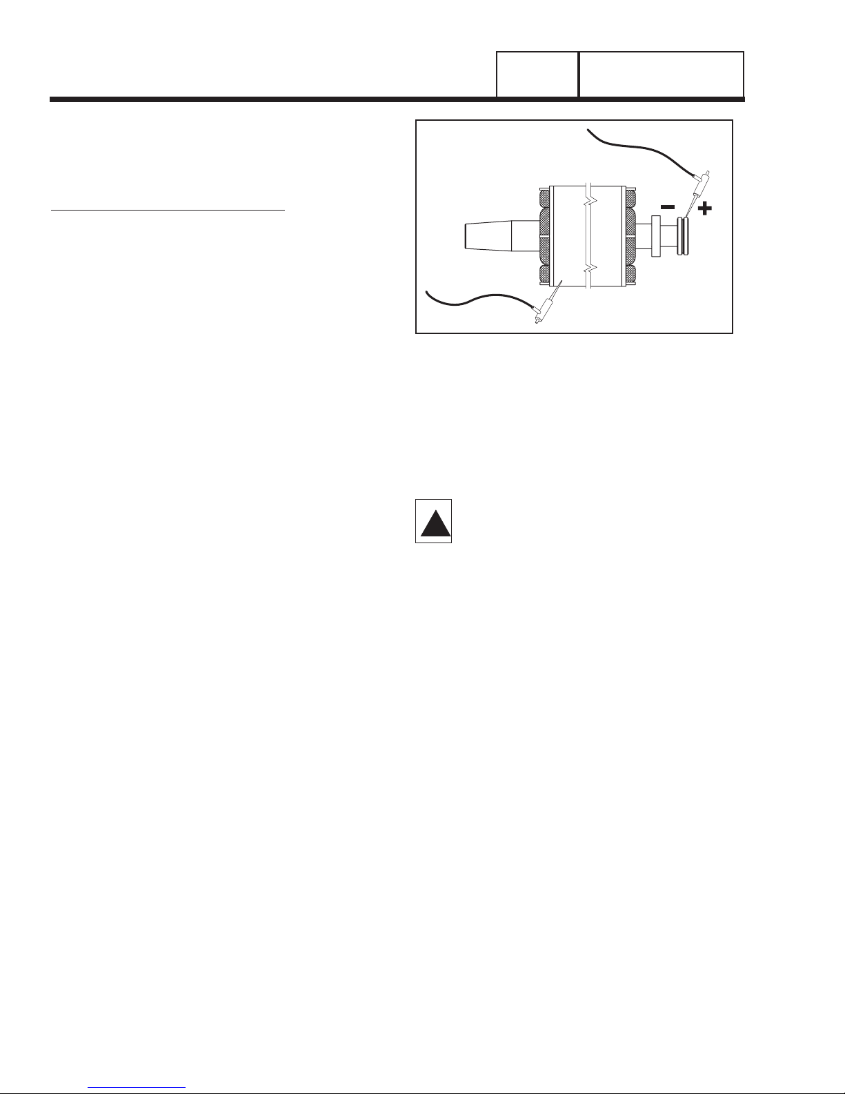
TESTING ROTOR INSULATION
Before attempting to test rotor insulation, either the
brush leads must be completely removed from the
brushes or the brush holders must be completely
removed. The rotor must be completely isolated from
other components before starting the test.
1.Connect the red tester lead to the positive (+) slip
ring (nearest the rotor bearing).
2.Connect the black tester probe to a clean frame
ground, such as a clean metal part of the rotor.
3.Turn the tester switch OFF.
4.Plug the tester into a 120 volts AC wall socket and
set the voltage switch to "500 volts".
5.Turn the tester switch ON and make sure the pilot
light has turned on.
6.Observe the breakdown lamp, then turn the tester
switch OFF. DO NOT APPLY VOLTAGE LONGER
THAN ONE (1) SECOND.
If the breakdown lamp came on during the one (1)
second test, cleaning and drying of the rotor may be
necessary. After cleaning and drying, repeat the insulation breakdown test. If breakdown lamp comes on
during the second test, replace the rotor assembly.
Figure 6. Testing Rotor Insulation
CLEANING THE GENERATOR
Caked or greasy dirt may be loosened with a soft
brush or a damp cloth. A vacuum system may be
used to clean up loosened dirt. Dust and dirt may also
be removed using dry, low-pressure air (25 psi maximum).
CAUTION: Do not use sprayed water to clean
the generator. Some of the water will be
retained on generator windings and terminals, and may cause very serious problems.
DRYING THE GENERATOR
To dry a generator, proceed as follows:
1.Open the generator main circuit breaker. NO ELECTRICAL LOADS MUST BE APPLIED TO THE
GENERATOR WHILE DRYING.
2.Disconnect all wires No. 4 from the voltage regulator.
3.Provide an external source to blow warm, dry air
through the generator interior (around the rotor and
stator windings. DO NOT EXCEED 185° F. (85°
C.).
4.Start the generator and let it run for 2 or 3 hours.
5.Shut the generator down and repeat the stator and
rotor insulation resistance tests.
!
PART 1
Page 12
GENERAL INFORMATION
SECTION 1.4
TESTING, CLEANING AND DRYING
RED TEST LEAD
BLACK TEST LEAD
GENERAL INFORMATION
SECTION 1.5
ENGINE-GENERATOR PROTECTIVE DEVICES
PART 1
Page 13
GENERAL
Standby electric power generators will often run unattended for long periods of time. Such operating parameters as (a) engine oil pressure, (b) engine temperature, (c) engine operating speed, and (d) engine
cranking and startup are not monitored by an operator
during automatic operation. Because engine operation will not be monitored, the use of engine protective
safety devices is required to prevent engine damage
in the event of a problem.
Prepackaged generator engines mount several engine
protective devices. These devices work in conjunction
with a control circuit board, to protect the engine
against such operating faults as (a) low engine oil
pressure, (b) high temperature, (c) overspeed, and (d)
overcrank. On occurrence of any one or more of those
operating faults, control board action will effect an
engine shutdown.
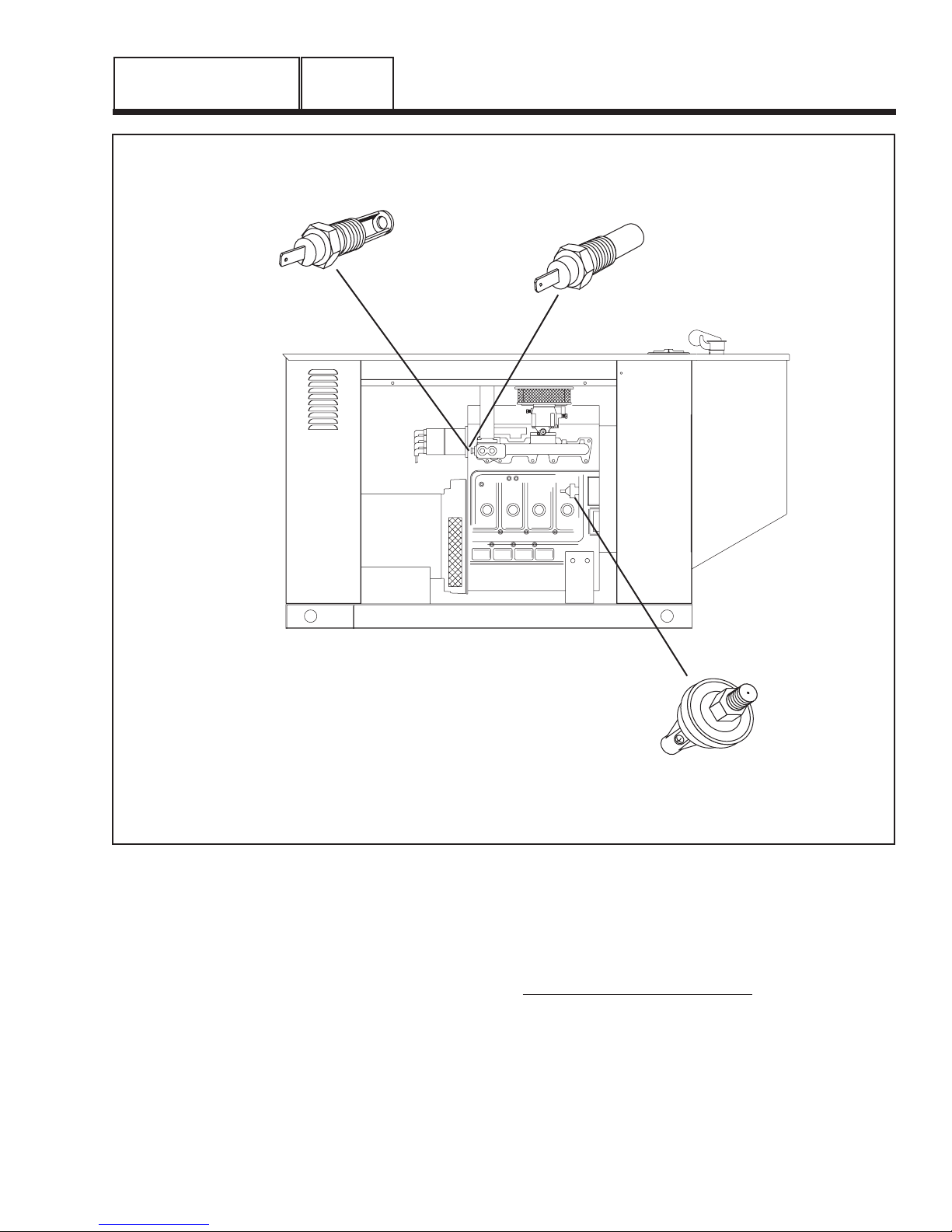
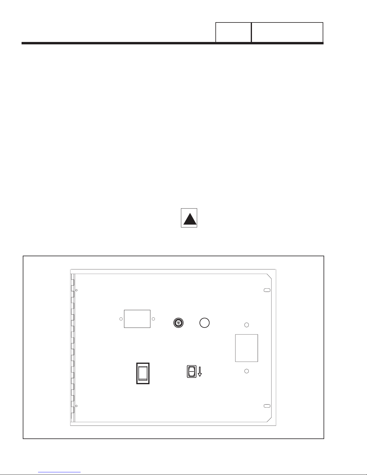
LOW OIL PRESSURE SHUTDOWN:
See Figure 1. Prepackaged generators with liquid
cooled engine are equipped with an oil pressure
switch having a closing pressure of about 10 psi.
Should oil pressure drop below that value, an automatic engine shutdown will occur. Circuit operation is
similar to that of air-cooled units.
Figure 1. Protective Devices on Liquid Cooled Engine
LOW COOLANT
LEVEL SWITCH
HIGH COOLANT
TEMPERATURE
SWITCH
OVERCRANK AND OVERSPEED
SHUTDOWN ARE CONTROLLED
BY THE CIRCUIT BOARD
LOW OIL
PRESSURE
SWITCH

PART 1
Page 14
GENERAL INFORMATION
SECTION 1.5
ENGINE-GENERATOR PROTECTIVE DEVICES
HIGH COOLANT TEMPERATURE SHUTDOWN:
The engine is equipped with a coolant temperature
switch. Should engine coolant temperature exceed
approximately 284° F. (140° C.), the engine will be
shut down automatically by control board action.
LOW COOLANT LEVEL SENSOR:
It is possible that engine coolant level might drop low
enough so that the high temperature switch is no
longer immersed in the liquid coolant. If this happens
engine temperatures could increase rapidly but the
temperature switch would not sense the high temperature condition and the engine would continue to run.
To prevent this occurrence, a low coolant level sensor
is provided. The sensor is immersed in cooling system liquid. If coolant level drops below the level of the
low coolant level sensor, the device will complete a
Wire 85 circuit to ground. Engine shutdown will occur.
OVERSPEED SHUTDOWN:
The control board on liquid cooled units receives AC
frequency (rpm) signals directly from the stator AC
power windings, via sensing leads S15 and S16.
Should AC frequency exceed approximately 72 Hz,
circuit board action will initiate an automatic engine
shutdown.
NOTE: For units rated 1800 rpm, 72 Hz is equal to
2160 rpm.
NOTE: The control board also uses the sensing
lead signals (S15, S16) (a) to terminate cranking
at about 50% of rated frequency, and (b) as an
“engine running” signal. The circuit board will not
initiate transfer of electrical loads to the
"Standby" source until sensing voltage and frequency is greater than 50 % of the unit’s rated
values.
OVERCRANK SHUTDOWN:
Automatic engine cranking and startup normally
occurs when the control board senses that utility
source voltage has dropped below approximately 60
percent of its nominal rated voltage and remains at
that low level longer than six (6) seconds. At the end
of six (6) seconds, control board action will energize a
crank relay and a run relay (both relays are on the
control board). On closure of the crank relay contacts,
control board action will deliver 12 volts DC to a control contactor (CC). The control contactor will energize and battery power will be delivered across its
closed contacts to the starter motor (SM). The engine
will then crank.
During a manual startup (AUTO-OFF-MANUAL
switch at "Manual"), action is the same as during an
automatic start, except that cranking will begin immediately when the switch is set to "Manual".
Control board action (during both a manual and an
automatic start) will hold the crank relay energized for
about 7-9 seconds. The relay will then de-energize for
about 7-9 seconds, and then energize again. In this
manner, the engine will be cranked for 7-9 seconds,
will rest for 7-9 seconds, and will crank again, and so
on until the engine starts.
If the engine has not started after approximately 90 seconds of these crank-rest cycles, cranking will automatically terminate and shutdown will occur. The control
board uses AC signals from the stator battery charge
windings as an indication that the engine has started.
Page 15
CONTROL PANEL
GENERAL:
See Figure 1 (Page 16). A typical prepackaged control
panel on units with liquid cooled engine includes: (a)
an auto-off-manual switch, (b) a fault indicator lamp,
(c) a 15 amp fuse, and (d) a set exercise switch.
AUTO-OFF-MANUAL SWITCH:
Use this switch to (a) select fully automatic operation,
(b) to crank and start the engine manually, and (c) to
shut the unit down or to prevent automatic startup.
1. AUTO position:
a.Select AUTO for fully automatic operation.
b.When AUTO is selected, circuit board will moni-
tor utility power source voltage.
c. Should utility voltage drop below a preset level
and remain at such a low level for a preset time,
circuit board action will initiate engine cranking
and startup.
d.Following engine startup, circuit board action
will initiate transfer of electrical loads to the
“Standby” source side.
e.On restoration of utility source voltage above a
preset level, circuit board action will initiate
retransfer back to the “Utility Source” side.
f. Following retransfer, circuit board will shut the
engine down and will then continue to monitor
utility source voltage.
2. OFF Position:
a.Set the switch to OFF to stop an operating
engine.
b.To prevent an automatic startup from occurring,
set the switch to OFF.
3. MANUAL Position:
a.Set switch to MANUAL to crank and start unit
manually.
b.Engine will crank cyclically and start (same as
automatic startup, but without transfer). The unit
will transfer if utility voltage is not available.
DANGER: WHEN THE GENERATOR IS
INSTALLED IN CONJUNCTION WITH AN
AUTOMATIC TRANSFER SWITCH, ENGINE
CRANKING AND STARTUP CAN OCCUR AT
ANY TIME WITHOUT WARNING (PROVIDING
THE AUTO-OFF-MANUAL SWITCH IS SET TO
AUTO). TO PREVENT AUTOMATIC STARTUP
AND POSSIBLE INJURY THAT MIGHT BE
CAUSED BY SUCH STARTUP, ALWAYS SET
THE AUTO-OFF-MANUAL SWITCH TO ITS
OFF POSITION BEFORE WORKING ON OR
AROUND THIS EQUIPMENT.
FAULT INDICATOR LAMP:
The fault indicator lamp will turn on in the event that
any one or more of the following engine fault conditions should occur: (a) low oil pressure, (b) high
coolant temperature, (c) low coolant level, (d) overspeed, and (e) overcrank.
15 AMP FUSE:
This fuse protects the DC control system, including
the control board, against overload. If the fuse has
blown, engine cranking and running will not be possible. Should fuse replacement become necessary, use
only an identical 15 amp replacement fuse.
THE SET EXERCISE SWITCH:
Use this switch to select the time and day for system
exercise.
TO SELECT AUTOMATIC OPERATION
The following procedure applies to those installations
in which the prepackaged home standby generator is
installed in conjunction with a prepackaged transfer
switch. Prepackaged transfer switches do not have an
intelligence circuit of their own. Instead, automatic
operation on prepackaged transfer switch and generator combinations is controlled by a control circuit
board housed in the generator.
To select automatic operation when a prepackaged
transfer switch is installed along with a prepackaged
home standby generator, proceed as follows:
1. Check that the prepackaged transfer switch main contacts are at their “Utility” position, i.e., the load is connected to the utility power supply. If necessary, manually actuate the switch main contacts to their “Utility” source side.
See Part 3 of this manual for instructions.
2. Check that utility source voltage is available to transfer
switch Terminal Lugs N1 and N2 (2-pole, 1-phase transfer
switches).
3.Set the generator’s AUTO-OFF-MANUAL switch to its
AUTO position.
4. Actuate the generator’s main line circuit breaker to its ON
or “Closed” position. With the preceding Steps 1 through
4 completed, a dropout in utility supply voltage below a
preset level will result in automatic generator cranking
and start-up. Following startup, the prepackaged transfer
switch will be actuated to its “Standby” source side, i.e.,
loads powered by the standby generator.
MANUAL TRANSFER TO “STANDBY” AND
MANUAL STARTUP
To transfer electrical loads to the "Standby" (generator) source and start the generator manually, proceed
!
GENERAL INFORMATION
SECTION 1.6
OPERATING INSTRUCTIONS
PART 1
PART 1
Page 16
GENERAL INFORMATION
SECTION 1.6
OPERATING INSTRUCTIONS
as follows:
1.On the generator panel, set the AUTO-OFF-MANUAL switch to OFF.
2.On the generator, set the main line circuit breaker
to it’s OFF or "Open" position.
3.Turn OFF the utility power supply to the transfer
switch, using whatever means provided (such as a
utility-source line circuit breaker).
4.Manually actuate the transfer switch main contacts
to their “Standby” position, i.e., loads connected to
the “Standby” power source side.
5.On the generator panel, set the AUTO-OFF-MANUAL switch to MANUAL. The engine should crank
and start.
6.Let the engine warm up and stabilize for a minute
or two at no-load.
7.Set the generator’s main line circuit breaker to its
ON or "Closed" position. The generator now powers
the electrical loads.
MANUAL SHUTDOWN AND RETRANSFER
BACK TO "UTILITY"
To shut the generator down and retransfer electrical
loads back to the "Utility" position, proceed as follows:
1.Set the generator’s main line circuit breaker to its
OFF or "Open" position.
2.Let the generator run at no-load for a few minutes,
to cool.
3.Set the generator’s AUTO-OFF-MANUAL switch to
OFF. Wait for the engine to come to a complete
stop.
4.Turn OFF the “Utility” power supply to the transfer
switch using whatever means provided (such as a
“Utility” source main line circuit breaker)
5.Manually actuate the prepackaged transfer switch
to its “Utility” power source side, i.e., “Load” connected to the “Utility” source.
6.Turn ON the “Utility” power supply to the transfer
switch, using whatever means provided.
7.Set the generator’s AUTO-OFF-MANUAL switch to
AUTO.
THE SET EXERCISE TIME SWITCH
The prepackaged home standby generator will start
and exercise once every seven (7) days, on a day
and at a time of day selected by the owner or operator. The set exercise time switch is provided to select
the day and time of day for system exercise.
See Part 5, Section 5.2 ("The 7-Day Exercise Cycle")
for instructions on how to set exercise time.
DANGER: THE GENERATOR WILL CRANK
AND START WHEN THE SET EXERCISE
TIME SWITCH IS SET TO "ON". DO NOT
ACTUATE THE SWITCH TO "ON" UNTIL
AFTER YOU HAVE READ THE INSTRUCTIONS IN SECTION 1.6.
!
Figure 1. Control Panel
HOURMETER
AUTO
OFF
MANUAL
FUSE
15-A
AGC
FAULT
INDICATOR
SET
EXERCISE
TIME
ON

Page 17
GENERAL INFORMATION
SECTION 1.7
AUTOMATIC OPERATING PARAMETERS
PART 1
INTRODUCTION
When the prepackaged generator is installed in conjunction with a prepackaged transfer switch, either
manual or automatic operation is possible. Manual
transfer and engine startup, as well as manual shutdown and retransfer are covered in section 1.7.
Selection of fully automatic operation is also discussed in that section. This section will provide a
step-by-step description of the sequence of events
that will occur during automatic operation of the system.
AUTOMATIC OPERATING SEQUENCES
PHASE 1 - UTILITY VOLTAGE AVAILABLE:
With utility source voltage available to the transfer
switch, that source voltage is sensed by a control
board in the generator panel and the circuit board
takes no action.
Electrical loads are powered by the "Utility" source
and the AUTO-OFF-MANUAL switch is set to AUTO.
PHASE 2 - UTILITY VOLTAGE DROPOUT:
If a dropout in utility source voltage should occur
below about 60 percent of the nominal utility source
voltage, a 12 second timer on the control board will
start timing. This timer is required to prevent false
generator starts that might be caused by transient utility voltage dips.
PHASE 3 - ENGINE CRANKING:
When the control board’s 12 second timer has fin-
ished timing and if utility source voltage is still below
60 percent of the nominal source voltage, control
board action will energize a crank relay and a run
relay. Both of these relays are mounted on the control
board.
Control board action will hold the crank relay energized for about 7-9 seconds. The relay will then be
de-energized for about 7-9 seconds, energized again
for 7-9 seconds, and so on. When the crank relay
energizes the engine will crank, when it is de-energized, engine cranking will stop. This cyclic action of
crank/rest, crank/rest, etc., will continue until either (a)
the engine starts, or (b) until ninety (90) seconds have
elapsed.
If the engine has not started within ninety (90) seconds, cranking will terminate and shutdown will occur.
On liquid cooled engine units, a fault indicator lamp
(LED) on the generator panel will illuminate.
If the engine starts, cranking will terminate when generator AC output frequency reaches approximately 30 Hz.
PHASE 4 - ENGINE STARTUP AND RUNNING:
The control board senses that the engine is running
by receiving a voltage/frequency signal from the generator stator windings.
When generator AC frequency reaches approximately
30 Hz, an engine warm-up timer on the control board
turns on. That timer will run for about fifteen (15) seconds. At the same time, an engine minimum run timer
will turn on.
The engine warm-up timer lets the engine warm-up
and stabilize before transfer to the "Standby" source
can occur.
The engine minimum run timer prevents a cold engine
from being shut down, as might happen if utility
source power is restored very quickly. The minimum
run timer will run for about 10-12 minutes. That
means the engine must run for 10-12 minutes before
it can be shut down automatically.
NOTE: The engine can be shut down manually at
any time, by setting the AUTO-OFF-MANUAL
switch to OFF.
PHASE 5 - TRANSFER TO “STANDBY”:
When the control board’s engine warm-up timer has
timed out, control board action completes a transfer
relay circuit to ground. The transfer relay is housed in
the prepackaged transfer switch enclosure.
The transfer relay energizes and transfer of loads to
the “Standby” power source occurs. Loads are now
powered by standby generator AC output.
PHASE 6 - “UTILITY” POWER RESTORED:
When utility source voltage is restored above about
80 percent of the nominal supply voltage, a fifteen
(15) second timer on the control board starts timing. If
utility voltage remains sufficiently high at the end of
fifteen (15) seconds, a “retransfer time delay” will start
timing and will time for about six (6) seconds.
PHASE 7 - RETRANSFER BACK TO “UTILITY”:
When the retransfer time delay has finished timing,
control board action will open a circuit to a transfer
relay (housed in the transfer switch). The transfer
relay will then de-energize and retransfer back to the
“Utility” source will occur. Loads are now powered by
“Utility” source power. On retransfer, an “engine cooldown timer” starts timing and will run for about one (1)
minute.
PHASE 8 - GENERATOR SHUTDOWN:
When the engine cool-down timer has finished timing,
and if the minimum run timer has timed out, engine
shutdown will occur.

PART 1
GENERAL INFORMATION
SECTION 1.7
AUTOMATIC OPERATING PARAMETERS
Page 18
AUTOMATIC OPERATING SEQUENCES CHART
SEQ. CONDITION ACTION SENSOR, TIMER OR OTHER
1 “Utility” source voltage is No action Voltage Dropout Sensor on control
available. circuit board.
2 “Utility” voltage dropout below A 6-second timer on control Voltage Dropout Sensor and 6
60% of rated voltage occurs. board turns on. second timer on control board.
3 “Utility” voltage is still below 6-second timer runs for 6 Voltage Dropout Sensor and 6
60% of rated voltage. seconds, then stops. second timer.
4 “Utility” voltage is still low after Control board action energizes a Control board crank and run
6 seconds. crank relay and a run relay. The relays.
engine cranks for 7-9 seconds,
rests for 7-9 seconds, and so on
until engine starts. See NOTE 1.
5 “Utility” voltage still low and Control board’s “engine warmup Engine Warmup Timer (15 seconds)
the engine has started. timer” and “engine minimum run Minimum Run Timer (13 minutes)
timer” both turn on.
6 Engine running and “engine Control board action energizes a Control board transfer relay circuit
warmup timer” times out. transfer relay in transfer switch Transfer switch transfer relay.
and transfer to “Standby” occurs.
7 Engine running and load is No further action Control board’s “voltage pickup
powered by “Standby” power. sensor” continues to seek an
acceptable “Utility voltage.
8 “Utility” source voltage is Control board’s “voltage pickup Voltage Pickup Sensor (80%)
restored above 80% of rated sensor” reacts and a “return to Return to Utility Timer (10 seconds)
source voltage. utility timer” turns on.
9 “Utility voltage still high after 6 “Return to utility timer” times out Return to Utility Timer
seconds.
10 “Utility” voltage still high. Control board action opens the Control board transfer relay circuit
transfer relay circuit to ground. Transfer switch transfer relay.
Transfer relay de-energizes and
retransfer to “Utility” occurs.
11 Engine still running, loads are Control board’s “engine cooldown control board’s Engine Cooldown
powered by “Utility” source. timer” starts running. Timer (1 minute)
12 After 1 minute, “engine cooldown Engine Cooldown Timer
timer” stops and control board’s control board Run Relay.
run relay de-energizes. Engine
shuts down.
13 Engine is shut down, loads are No action. Voltage Dropout Sensor on control
powered by “Utility” source. circuit board.
Return to Sequence 1.
Note1: In Sequence 4, if engine has not started in 90 seconds cranking will end and shutdown will occur.
Page 19
PART TITLE PAGE
2.1 Description and Major Components 20
2.2 AC Output Operational Analysis 24
2.3 AC Output Troubleshooting Flow Charts 26
Problem 1 - Generator Produces ZeroVoltage or
ResidualVoltage 26
Problem 2 - Generator Produces
LowVoltage at No-Load 28
Problem 3 - Generator Produces High
Voltage at No-Load 28
Problem 4 -Voltage and Frequency Drop
ExcessivelyWhen Loads Are Applied 29
2.4 AC Output Diagnostic Tests 30
TABLE OF CONTENTS
1.5 LITER PREPACKAGED
HOME STANDBY
GENERATORS
PART 2
PREPACKAGED
LIQUID-COOLED
AC GENERATORS
TEST DESCRIPTION ......................................PAGE
1 Check Main Circuit Breaker ................................ 30
2 Check AC Output Voltage .................................. 31
3 Test Excitation Circuit Breaker .......................... 31
4 Test Thermal Protector ...................................... 32
5 Fixed Excitation Test/Rotor
Amp Draw Test .................................................. 32
6 Wire Continuity .................................................. 33
7 Check Field Boost .............................................. 33
8 Testing the Ststor with a VOM ............................ 34
9 Resistance Check of Rotor Circuit .................... 35
TEST DESCRIPTION ......................................PAGE
10 Check Brushes
and Slip Rings .................................................... 35
11 Test Rotor Assembly .......................................... 35
12 Check AC Output Frequency ............................ 36
13 Check and Adjust Governor Board
and Stepper Motor .............................................. 36
14 Check and Adjust
Voltage Regulator .............................................. 38
15 Check Voltage and Frequency Under Load ...... 38
16 Check for Overload Condition ............................ 38
17 Check Engine Condition .................................... 38

INTRODUCTION
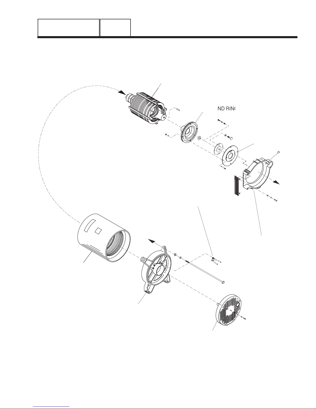
This section covers the major components of the AC
generator proper, i.e., those generator assemblies
that provide for the production of AC electrical power.
The single bearing rotor (revolving field) is driven by a
1.5 liter, liquid cooled gas engine. The rotor is coupled to the engine flywheel, by means of a flexible
coupling and a fan and ring gear assembly, so the
engine crankshaft and rotor operate at the same
speed.
Major components of the AC generator are shown in
Figure 1 on the next page. These components are (a)
a flexible coupling, (b) fan and ring gear, (c) rotor, (d)
blower housing, (e) stator assembly, (f) rear bearing
carrier, and (g) a rear bearing carrier cover.
BLOWER HOUSING
The blower housing is bolted to the engine and supports the engine end of the AC generator. It houses
the fan and ring gear assembly. A cutout area on one
side of the housing allows a blower air outlet screen
to be mounted.
FLEXIBLE DISK
A flexible disk bolts to the engine flywheel and to the
fan and ring gear assembly. The disk maintains proper alignment between the engine and generator parts.
FAN AND RING GEAR ASSEMBLY
The fan and ring gear assembly are retained to the
flexible disk which, in turn, is retained to the engine
flywheel. The fan draws cooling air into the generator
interior through slots in a rear bearing carrier cover,
then expels the heated air outward through a screen
on the blower housing. The ring gear teeth mate with
teeth on a starter motor pinion gear, when the engine
is cranked.
ROTOR ASSEMBLY
The rotor assembly on units rated 1800 rpm is a 4pole type, having two north magnetic poles and two
south magnetic poles.
The rear end of the rotor is bolted and keyed to the
fan and ring gear. A ball bearing has been pressed
onto the rotor’s front shaft, which is retained, in a
machined bore in the rear bearing carrier.
A positive (+) and a negative (-) slip ring is provided
on the rotor shaft that retains the ball bearing.
Brushes will ride on these slip rings.
The combination of slip rings and brushes allow rotor
excitation current to be transmitted from stationary
components into the rotating rotor windings. The positive (+) slip ring is the one nearest the rotor bearing.
REAR BEARING CARRIER
The rear bearing carrier supports the front of the generator. Mounting feet at the carrier bottom permit the
carrier to be bolted to the generator’s mounting base.
A machined bore, in the center of the carrier, accepts
the rotor bearing. Bosses allow for the retention of
brush holders. Long stator bolts pass through holes in
the carrier’s outer periphery, to sandwich and retain
the stator can between the carrier and the blower
housing. A rear bearing carrier gasket helps prevent
dust from entering the bearing area.
STATOR ASSEMBLY
The stator can is sandwiched between the blower
housing and the rear bearing carrier, and retained in
that position by four (4) stator bolts.
A notched cutout has been provided in the rear bearing carrier end of the stator can. A rubber grommet
has been placed into that notch, for protection of the
stator leads that are brought out of the stator.
REAR BEARING CARRIER PLATE
This plate is retained to the rear bearing carrier by
four (4) capscrews, lockwashers and flatwashers. The
plate provides slotted air inlet openings for the passage of cooling and ventilating air into the generator.
BRUSH HOLDERS AND BRUSHES
Brushes are retained in a brush holder which is
retained to drilled and threaded bosses on the rear
bearing carrier. In most cases, two brush holders are
used having two brushes per holder. Brush holders
are precisely positioned so that one of the two brushes slides on a positive (+) slip ring, the other on a
negative (-) slip ring. The positive (+) brush and slip
ring are nearest the rotor bearing. The positive (+)
side of the DC excitation circuit (Wire No. 4, red) connects to the positive (+) brush; the negative (-) or
grounded side (Wire No. 0) to the negative (-) brush.
Brushes and brush holders are illustrated in Figure 2,
on Page 22.
PART 2
Page 20
PREPACKAGED LIQUID
COOLED AC GENERATORS
SECTION 2.1
DESCRIPTION AND MAJOR COMPONENTS
PREPACKAGED LIQUID
COOLED AC GENERATORS
SECTION 2.1
DESCRIPTION AND MAJOR COMPONENTS
PART 2
Page 21
S
OR
er
g
OR
OUSING
SK
S
R
E
e
t
Figure 1. Generator Major Components
ROT
FLEXIBLE DI
TAT
REAR BEARING CARRIE
BRUSH HOLDERS AND BRUSHE
To Blow
Housin
REAR BEARING CARRIER PLAT
To Engin
rankshaf
BLOWER H
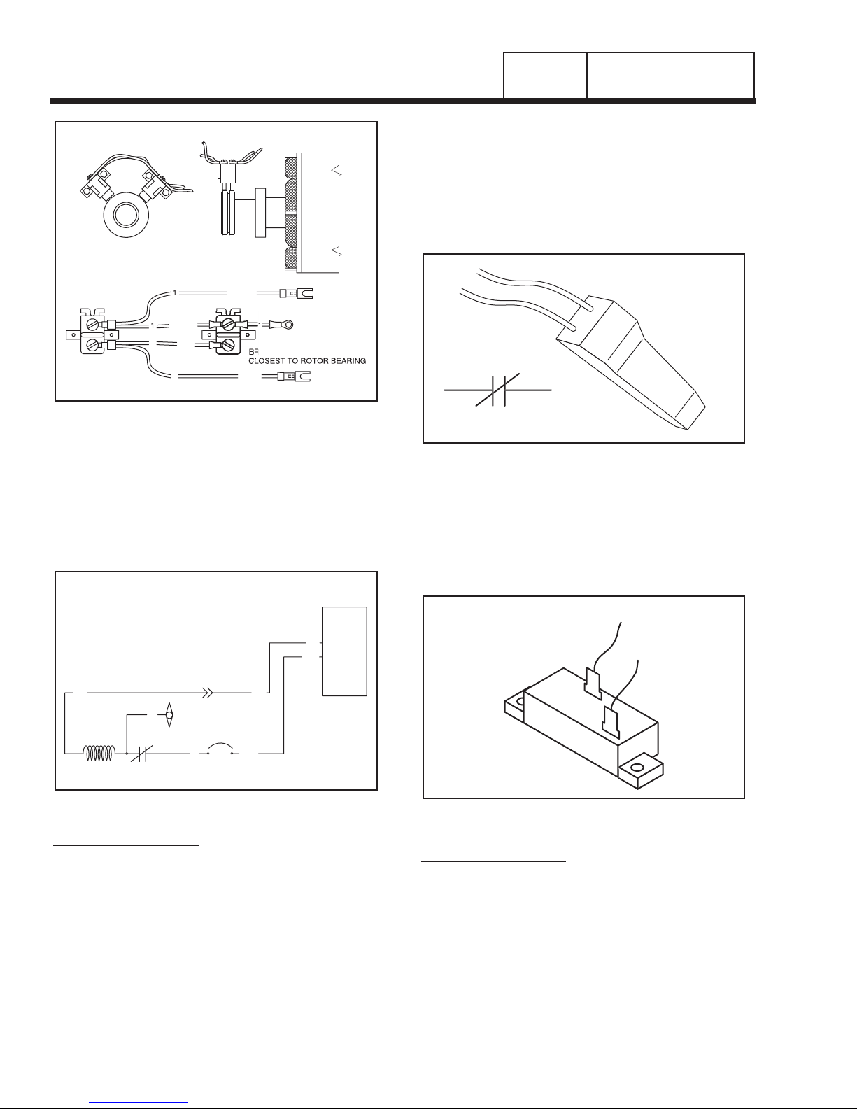
Figure 2. Brush Holders and Brushes
THE EXCITATION CIRCUIT
AC output from the stator excitation (DPE) winding is
delivered to the voltage regulator, via a thermal protector (TP), Wire No. 2, an excitation circuit breaker
(CB1), Wire No. 162, and Wire No. 6. This is “unregulated” excitation current.
Figure 3. Schematic - Excitation Circuit
THERMAL PROTECTOR:
This normally closed thermal switch protects the stator
windings against excessively high internal temperatures. The switch is physically imbedded in the stator
windings and electrically connected in series with the
DPE winding AC output to the regulator. If internal stator temperatures exceed a safe value, the switch contacts will open and the DPE output to the voltage regulator will be terminated. Without excitation current flow
to the rotor, generator AC output voltage will drop to a
value commensurate with rotor residual magnetism.
The thermal protector is self-resetting. That is, when
internal stator temperatures drop to a safe value, its
contacts will re-close and normal DPE output to the
regulator will resume.
Wire No. 5 is a thermal protector “bypass” lead. If the
thermal switch has failed in its open position, it can be
bypassed. The Wire No. 5 bypass lead is brought out
of the stator and has a wire nut on its end.
Figure 4. The Thermal Protector
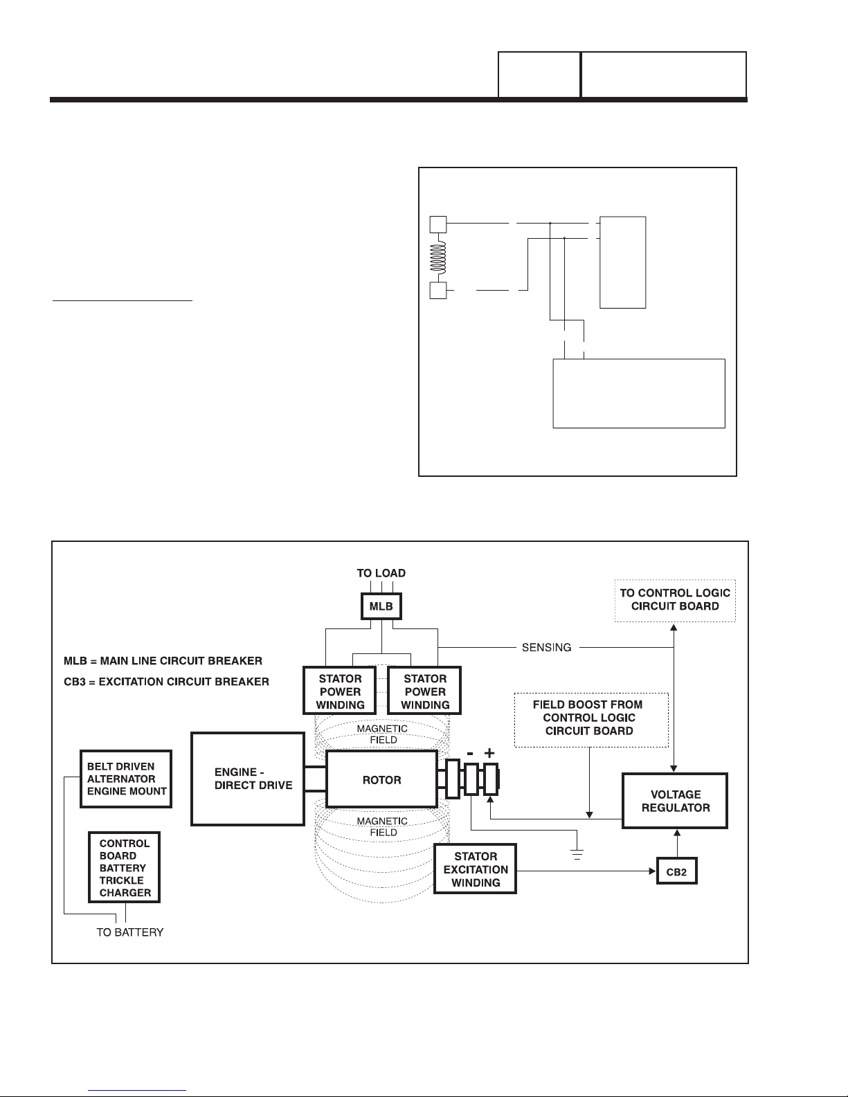
EXCITATION CIRCUIT BREAKER:
This circuit breaker protects the regulator against high
voltage surges. If the breaker has tripped open, loss
of excitation current will occur. Stator power winding
AC output voltage will then drop to a value commensurate with residual magnetism in the rotor. The
breaker is self-resetting.
Figure 5. Excitation Circuit Breaker
VOLTAGE REGULATOR:
See Figure 6. Unregulated AC output from the stator
DPE winding is delivered to the voltage regulator, via
Wires No. 6 and 162. Stator power winding AC voltage and frequency signals are delivered to the regulator, via “sensing” Wires No. S15 and S16. The regulator rectifies the DPE output and, based on the sensing
lead signals, regulates the DC current output. An LED
(light emitting diode) is incorporated on the regulator.
This red light senses the “sensing” (S15/S16) input.
62
CK
CK
D
D
PART 2
Page 22
PREPACKAGED LIQUID
COOLED AC GENERATORS
SECTION 2.1
DESCRIPTION AND MAJOR COMPONENTS
+ -
BLA
BLA
H WITH RED LEA
RE
DPE - STATOR EXCITATION WINDING
CB2 - EXCITATION CIRCUIT BREAKER
VR - VOLTAGE REGULATOR
TP - THERMAL PROTECTOR
6
DPE TP
WIRE
5
NUT
(BYPASS)
2
CB2
6
162
162
6
VR
1
PREPACKAGED LIQUID
COOLED AC GENERATORS
SECTION 2.1
DESCRIPTION AND MAJOR COMPONENTS
PART 2
Page 23
Figure 6. Prepackaged Voltage Regulator
If the red LED goes “out”, sensing signals to the regulator have been lost. The following rules apply:
• Loss of sensing can be caused by an “open” circuit
condition in sensing leads S15 and S16. These
sensing leads also operate the generator’s panel
mounted AC frequency meter. Thus, if the red LED
is out, it may be assumed that an open circuit exists
in the sensing circuit.
• Loss of sensing to the regulator will usually result in
a “full field” condition and resultant high voltage output from stator AC power winding. The maximum
voltage that regulator action can deliver is limited by
a “clamming” action on the part of the regulator.
• A complete open circuit condition in the stator AC
power windings will cause loss of sensing voltage
and frequency. However, this will result in a zero
voltage output from the stator windings.
Based on the “sensing” signals, the regulator delivers
direct current (DC) to the rotor, via Wire No. 4 and the
positive (+) brush and slip ring. This regulated current
flows through the rotor and to frame ground, via the
negative (-) slip ring and brush and Wire No. 1. The
following apply:
• The concentration of magnetic flux lines around the
rotor will be proportional to the regulated excitation
current flow through the rotor plus any residual
magnetism.
• An increase in excitation current flow through the
rotor windings will increase the concentration of
“magnetic flux” lines around the rotor which, in turn,
will increase the AC voltage induced into the stator
AC power windings.
FIELD BOOST
See Figure 7. The prepackaged system provides a
“field boost” feature. Field boost, in effect, “flashes the
field” whenever the engine is cranking to ensure an
early “pickup voltage” in the stator windings.
A field boost diode and a field boost resistor are
installed in a printed circuit board. Field boost DC output to the rotor is reduced to approximately 9-10 volts
by the field boost resistor.
Manual and automatic cranking is initiated by PCB
board action, when that board energizes a crank relay
(K1). When the relay is energized, battery voltage is
delivered across its closed contacts and to the rotor,
via a field boost resistor, field boost diode, and Wire
No. 4. Notice that field boost current flow is available
only while the engine is cranking.
Figure 7. The Field Boost Circuit
(from Schematic Drawing #0F5244)
0
6
4
4
S16
S15
162
1
AR
RED
4
1
4
0
4
VR
4
0
2
17A
7D119
5
PCB
16
10
12
E
4
3
14
15
13
1
B
ROTOR RESIDUAL MAGNETISM
The generator revolving field (rotor) may be considered to be a permanent magnet. Some ‘residual”
magnetism is always present in the rotor. This residual magnetism is sufficient to induce a voltage into
the stator AC power windings that is approximately 212 volts AC.
FIELD BOOST
FIELD BOOST CIRCUIT:
When the engine is cranking, direct current flow is
delivered from a circuit board to the generator rotor
windings, via Wire 4.
The field boost system is shown schematically in
Figure 2. Manual and automatic engine cranking is
initiated by circuit board action, when that circuit
board energizes a crank relay. Battery voltage is then
delivered to field boost Wire 4 (and to the rotor), via a
field boost resistor and diode. The crank relay, field
boost resistor and diode are all located on the circuit
board.
Notice that field boost current is available only while
the crank relay is energized, i.e., while the engine is
cranking.
Field boost voltage is reduced from that of battery
voltage by the resistor action and, when read with a
DC voltmeter, will be approximately 9 or 10 volts DC.
Figure 7. The Field Boost Circuit
(from Schematic Drawing #0F5244)
Figure 1. Operating Diagram of AC Generator
PART 2
Page 24
PREPACKAGED LIQUID
COOLED AC GENERATORS
SECTION 2.2
OPERATIONAL ANALYSIS
1
AR
RED
4
1
4
0
4
VR
4
0
2
13
1
B
17A
7D119
5
PCB
16
10
12
E
4
3
14
15

PREPACKAGED LIQUID
COOLED AC GENERATORS
SECTION 2.2
OPERATIONAL ANALYSIS
PART 2
Page 25
OPERATION
STARTUP:
When the engine is started, residual plus field boost
magnetism from the rotor induces a voltage into the
stator AC power windings and the stator excitation or
DPE windings. In an “on-speed” condition, residual
plus field boost magnetism are capable of creating
approximately one-half the unit’s rated voltage.
ON-SPEED OPERATION:
As the engine accelerates, the voltage that is induced
into the stator windings increases rapidly, due to the
increasing speed at which the rotor operates.
FIELD EXCITATION:
An AC voltage is induced into the stator excitation
(DPE) windings. The DPE winding circuit is completed
to the voltage regulator, via Wire 2, excitation circuit
breaker, Wire 162, and Wire 6. Unregulated alternating current can flow from the winding to the regulator.
The voltage regulator “senses” AC power winding
output voltage and frequency via stator Wires S15
and S16.
The regulator changes the AC from the excitation
winding to DC. In addition, based on the Wires S15
and S16 sensing signals, it regulates the flow of direct
current to the rotor.
The rectified and regulated current flow from the regulator is delivered to the rotor windings, via Wire 4,
and the positive brush and slip ring. This excitation
current flows through the rotor windings and is directed to ground through the negative (-) slip ring and
brush, and Wire 1.
The greater the current flow through the rotor windings, the more concentrated the lines of flux around
the rotor become.
The more concentrated the lines of flux around the
rotor that cut across the stationary stator windings,
the greater the voltage that is induced into the stator
windings.
Initially, the AC power winding voltage sensed by the
regulator is low. The regulator reacts by increasing
the flow of excitation current to the rotor until voltage
increases to a desired level. The regulator then maintains the desired voltage. For example, if voltage
exceeds the desired level, the regulator will decrease
the flow of excitation current. Conversely, if voltage
drops below the desired level, the regulator responds
by increasing the flow of excitation current.
AC POWER WINDING OUTPUT:
A regulated voltage is induced into the stator AC
power windings. When electrical loads are connected
across the AC power windings to complete the circuit,
current can flow in the circuit. The regulated AC
power winding output voltage will be in direct proportion to the AC frequency. For example, on units rated
120/240 volts at 60 Hz, the regulator will try to maintain 240 volts (line-to-line) at 60 Hz. This type of regulation system provides greatly improved motor starting capability over other types of systems.
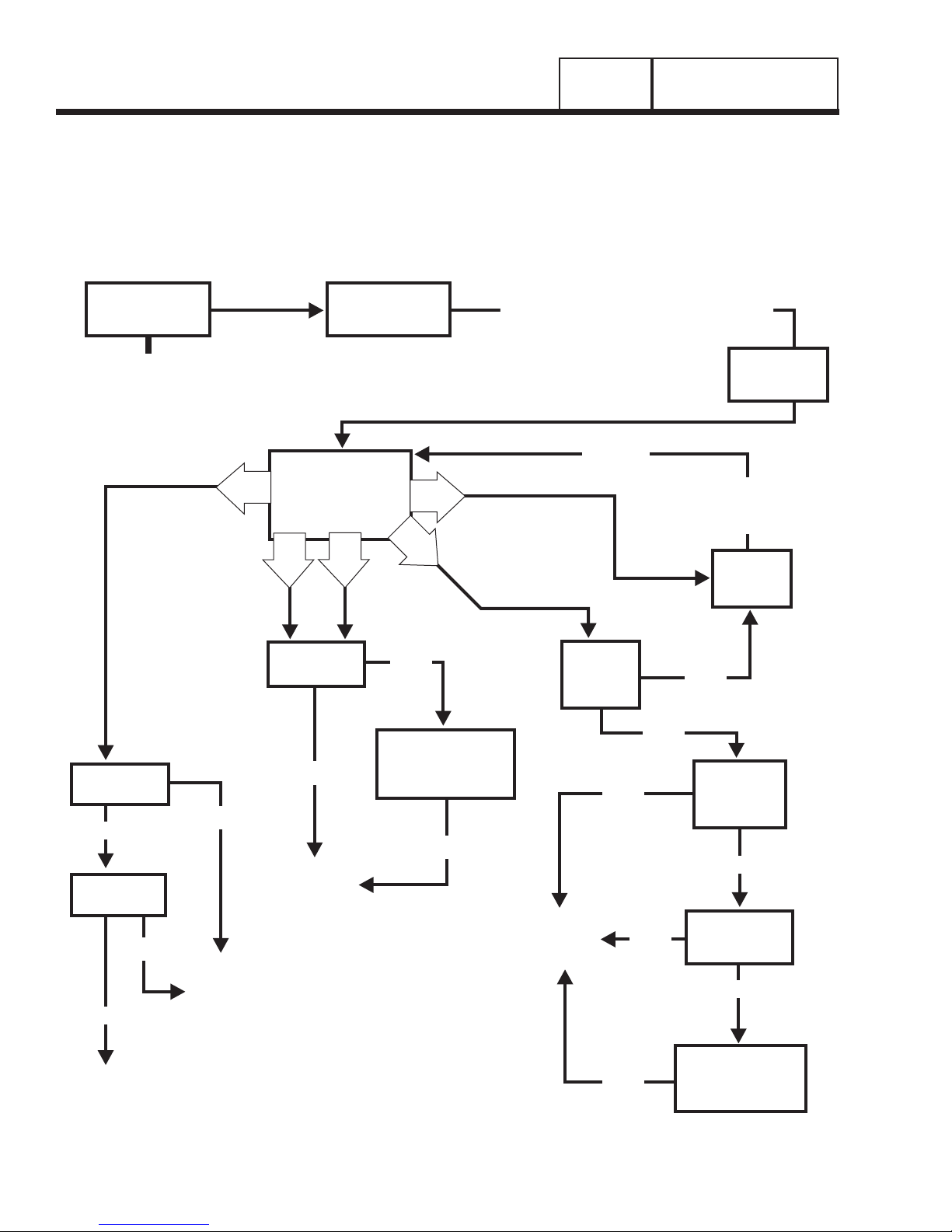
Use the “Flow Charts” in conjunction with the detailed
instructions in Section 2.4. Test numbers used in the
flow charts correspond to the numbered tests in
Section 2.4.
The first step in using the flow charts is to correctly
identify the problem. Once that has been done, locate
the problem on the following pages. For best results,
perform all tests in the exact sequence shown in the
flow charts.
PART 2
Page 26
PREPACKAGED LIQUID
COOLED AC GENERATORS
SECTION 2.3
TROUBLESHOOTING FLOW CHARTS
Problem 1 - Generator Produces Zero Voltage or Residual Voltage
TEST 1 - CHECK
MAIN CIRCUIT
BREAKER
RESET TO
“ON”
OR REPLACE
IF BAD
A
PERFORM FIXED
TEST 3 - TEST
EXCITATION
CIRCUIT BREAKER
TEST 5 -
EXCITATION /
ROTOR AMP
DRAW
G
D
B
C
GOOD -PROCEED
BAD -PROCEED, REPLACE AFTER TESTS
CONCLUDE
TEST 4 - TEST
THERMAL
PROTECTOR
RE-TEST
REPAIR
OR REPLACE
FUSES
CHECK
VOM
FUSES
TEST 6 - WIRE
CONTINUITY
GOOD
TEST 7 -
FIELD BOOST
BAD
GOOD
REPLACE
VOLTAGE
REGULATOR
BAD
REPAIR
OR
REPLACE
THEN
RETEST
TEST 8 -TEST
S TATO R
BAD
REPAIR
OR
REPLACE
GOOD
PERFORM STATOR
INSULATION
RESISTANCE TEST
BAD
TEST 9 -
CHECK
ROTOR
CIRCUIT
REPAIR
OR
REPLACE
BAD
BAD
GOOD
BAD
BAD
PERFORM ROTOR
RESISTANCE TEST
TEST 10 -
CHECK
BRUSHES &
SLIP RINGS
GOOD
TEST 11 -
TEST ROTOR
ASSEMBLY
GOOD
INSULATION
 Loading...