

Guardian CORE SERIES, 2211-L Owner's Manual
Owner’s Manual
● Please read and understand this manual and safety instructions carefully before installation.
● The Opener WILL NOT CLOSE until the Photo Eye Safety System is properly installed and aligned.
● REGULARLY CHECK and TEST the Opener according to the safety label to ENSURE SAFE OPERATION.
● Retain this manual for future reference.
GDO Manual Revised: 03-17
GDOMU10A-7
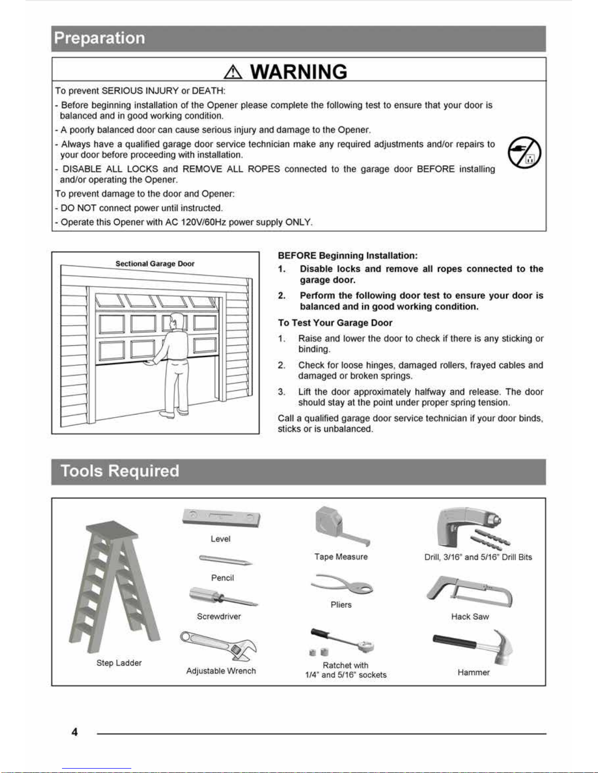
WARNING:
To reduce the risk of injury to persons - Use this operator only with Residential Sectional Garage doors.
Serial # __ __ __ __ __ __ __ Date Installed __ __ /__ __ /__ __ __ __
Located on the bar code label on top of your opener.
The illustrations used in this instruction manual may differ from the actual product you have purchased.

1
Courtesy light turns on/flashes with audible ‘click’.
(If light bulb is not installed, ‘click’ represents the light)
DO NOT connect power
Please connect power
Symbols and Icons
!
WARNING
Installation hardware
Introduction
Symbols and Icons 1
Inventory 2
Read and Follow These Important Safety Instructions 3
Preparation / Door Balance Test 4
Tools Required 4
Assembly
T-rail Assembly and Tensioning 5
Mounting Header Bracket 6
Installation
Attaching the Opener Assembly to Header Bracket 7
Mounting Door Bracket 7
Mounting Opener to Ceiling 8
Attaching Door Arms 9
Installing Light and Emergency Release Handle 10
Wiring
Wiring Instructions 11
Connecting Photo Eye Safety System 12
Connecting Push Button 13
Connecting Power 14
Adjustment
Aligning the Photo Eye Safety System 14
Travel Limit Adjustment 15
Force Adjustment 16
Final Adjustment and Testing 17
Operation
Programming Remote Controls* (OPTIONAL) 18
Operating the Opener 19-20
Maintenance 21
Troubleshooting 21
Repair Parts and Service
Installation and Accessory Parts 22
Opener Assembly parts 23
Warranty 24
Table of Contents
READ WARNINGS CAREFULLY to prevent SERIOUS INJURY or
DEATH caused by electrocution or mechanical hazard.
2
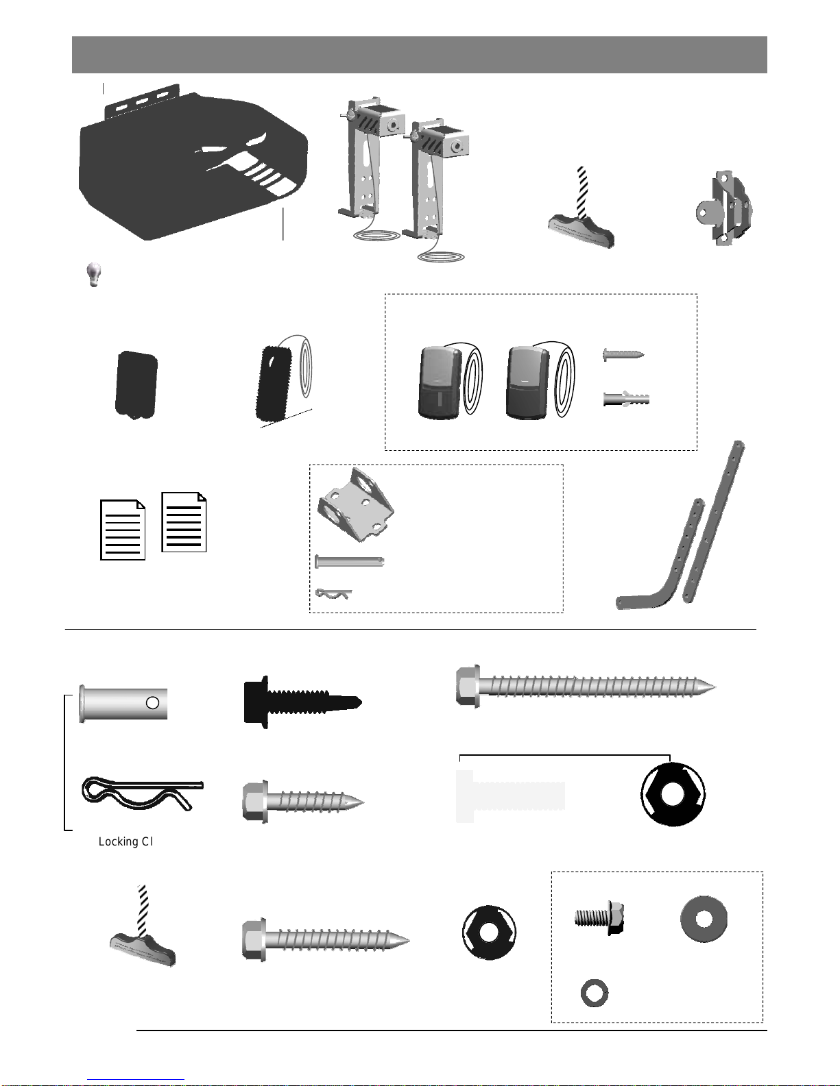
Emergency Release Handle
+ Rope
Literature + Safety Labels
Photo Eye Safety System
Door Bracket
Door Arms
Inventory
Remote Control
Push Button
Header Bracket
Clevis Pin Long x1
5/16’’ x 2-1/4’’
Hitch Pin — Locking Clevis Pins x1
x 2
Hitch Pin
— Locking Clevis Pins
x 2
Lag Screw 5/16” x 1-5/8”
— Door Bracket / Mounting Opener
Bolt 5/16” -18 x 1”
5/16” Flange Nut
x 6
x 6
x 4
x 2
Clevis Pin — Door arms
5/16” x 1”
INSTALLATION HARDWARE, LOCATED IN HARDWARE BAG (SHOWN IN ACTUAL SIZE 1:1)
Lag Screw 5/16” x 2 1/2”
— Header Bracket / Mounting Opener
x 2
x 4
Emergency Release Handle
+ Rope
Flange Nut
1/4” -20
Lag Screw 1/4” x 1”
— Door Bracket
x 2
Lag Screw 1/4” x 1”
— Photo Eye System
Opener Unit + Lamp Dome
( Light bulb are not included )
Hexagonal Screw
#
10 - 24 x 1/2”
Spring Washer
#
10
Washer #10
x 1
x 1
x 1
x 1
— Door arms / Mounting Opener
T-rail Assembly
Drywall Anchor
x 2
x 2
Screw #6 x 1”
Door Control included in some models
3-FDCC
1-FDCC
Standard Door Control

5
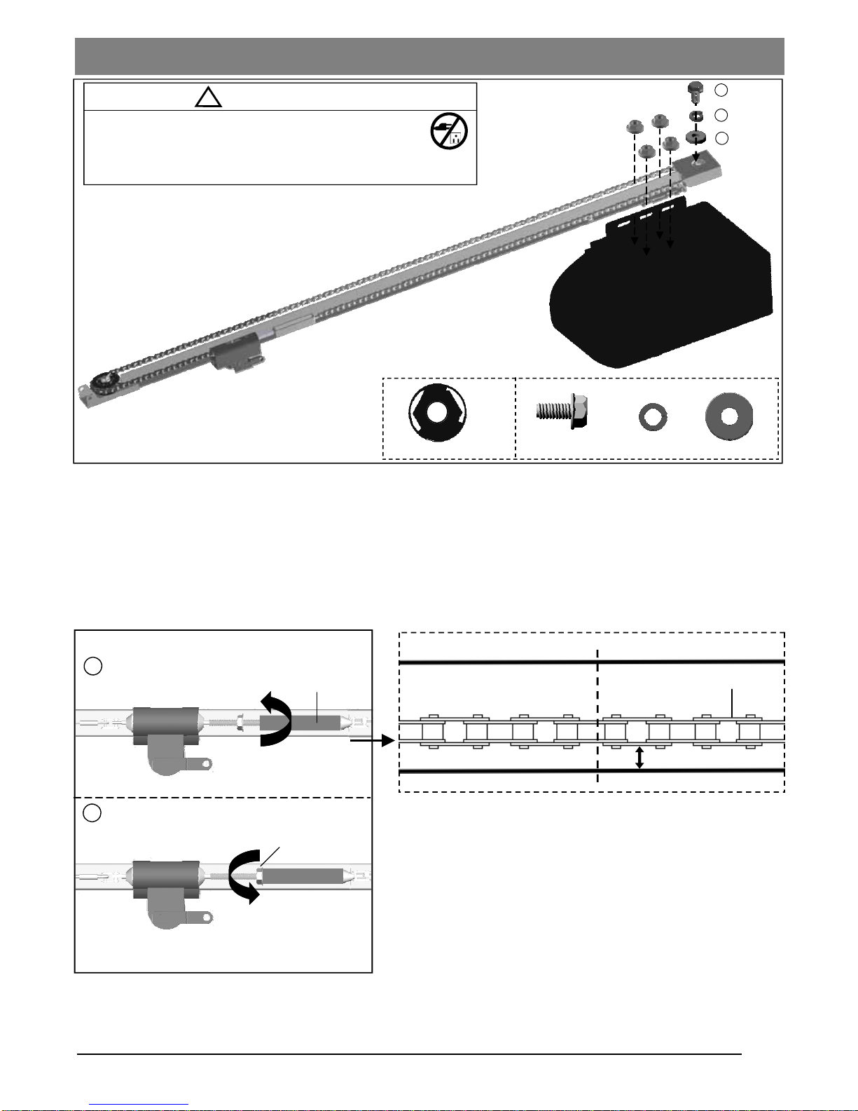
Fig.2
1
Tighten until...
2
Tighten nut
Flange Nut
Chain to Cable Connector
To Tighten the Chain:
Follow steps shown in Fig.2 to tighten the chain:
1. Turn the Chain-to-Cable Connector on the Trolley Shaft
until the chain is about 1/4” (6mm) above the base of the
rail. Compare with the illustration below.
2. Tighten the Flange Nut on Trolley Shaft against the Chain-to
-Cable Connector.
Notice
During operation, it is normal for the chain to appear loose when
the door is closed. If the chain returns to the position as shown
below when the door is opened, the chain is adjusted properly.
DO NOT re-tighten the chain.
When performing maintenance, always PULL the Emergency
Release to DISCONNECT the door from Opener before adjusting
the chain.
1/4” (6mm)
Base of Rail
Mid-point of rail assembly
Chain
Top of Rail
Actual Size
T-rail Assembly and Tensioning
Fig.1
!
CAUTION
- DO NOT connect power until instructed.
- To prevent INJURY, keep hands and fingers away
from joints and possible sharp edges.
- Wear gloves when installing chain and cable.
2
3
4
1/4” Flange Nut x 4
Screw
Spring Washer Washer
To Assemble the Rail
Align the pre-assembled T-rail on the top of opener in the direction as shown in Fig.1.
Secure the T-rail to the opener firmly using 1/4” flange nut x 4.
Final Step to T-Rail Installation
Fasten the Screw(2) to the motor shaft with spring washer(3) and washer(4) in between.
Note: The chain or belt rail assembly comes pre-tensioned from the factory. If installing with the optional belt rail,
follow the same adjustment steps.
#
10 - 24 x 1/2”


 Loading...