

Page 1
Introduction
1
Applicable Safety Standards
1
Worker Classifications
1
Safety Information
6
Product Specific Applications
1-2
Limitations
2-3
Components and Specifications
3-4
Maintenance, Cleaning, and Storage
5
Inspection
5
Installation and Use
4
Inspection Log
5
Labels
7
Product Name: Vertical Lifeline Assembly (VLA)
Instruction Manual
Part #: 01310; 01320; 01323; 01324; 01325; 01326; 01327; 11318; 11320; 01330; 01340; 01350;
01360; 01365; 01345; 11329; 11330; 11331; 11332; 11333; 11334; 11335; 11321; 11322; 11323;
11324; 11325; 11326; 11327; 11328
Do not throw away these instructions!
Read and understand these instructions before using equipment!
Page 2
Introduction
Thank you for purchasing a Guardian Fall
Protection VLA. This manual must be read
and understood in its entirety, and used as
part of an employee training program as
required by OSHA or any applicable state
agency.
User Information
Date of First Use:
Serial #:
Trainer:
User:
Applicable Safety Standards
When used according to instruction specifications, this product meets or exceeds all applicable OSHA 1926
Subpart M, OSHA 1910, ANSI Z359.1-2007, and ANSI A10.32-2012 standards for fall protection. Applicable
standards and regulations depend on the type of work being done, and also might include state regulations if
applicable. Consult regulatory agencies for more information on personal fall arrest systems and associated
components.
Worker Classifications
!
CAUTION
Understand the following definitions of those who
work near or who may be exposed to fall hazards.
Qualified Person: A person with an accredited degree or certification, and with extensive experience or
sufficient professional standing, who is considered proficient in planning and reviewing the conformity of fall
protection and rescue systems.
It is the responsibility of a Qualified or Competent person to supervise the job site and ensure all
applicable safety regulations are complied with.
Product Specific Applications
!
WARNING
Use of equipment in unintended applications may result in serious
injury or death. Maximum 1 attachment per connection point.
Personal Fall Arrest: VLAs may be used in Personal Fall Arrest applications to support a MAXIMUM
1 Personal Fall Arrest System (PFAS). Structure must withstand loads applied in the directions
permitted by the system of at least 5,000 lbs. Maximum free fall is 6‘. MAXIMUM combined length
of fall arrester, lanyard extension, and D-ring is 36”. Applicable D-ring: Dorsal.
Guardian Fall Protection 6305 S. 231st St., Kent, WA 98032 USA phone: (800) 466-6385 fax: (800) 670-7892 www.guardianfall.com
1
This and any other included instructions
must be made available to the user of the
equipment. The user must understand how
to safely and effectively use the VLA, and
all fall safety equipment used in combination
with the VLA.
Authorized Person: A person who is assigned by their employer to work around or be subject to potential or
existing fall hazards.
Competent Person: A highly trained and experienced person who is ASSIGNED BY THE EMPLOYER to be
responsible for all elements of a fall safety program, including, but not limited to, its regulation, management,
and application. A person who is proficient in identifying existing and predictable fall hazards, and who has
the authority to stop work in order to eliminate
hazards.
Page 3
Guardian Fall Protection 6305 S. 231st St., Kent, WA 98032 USA phone: (800) 466-6385 fax: (800) 670-7892 www.guardianfall.com
2
For all applications: worker weight capacity range
(including all clothing, tools, and equipment) is 130-310 lbs.
Restraint: VLAs may be used in Restraint applications. Restraint systems prevent workers from
reaching the leading edge of a fall hazard. Always account for fully deployed length of lanyard/VLA.
Structure must withstand loads applied in the directions permitted by the system of at least
1,000 lbs. No vertical free fall is permitted. Restraint systems may only be used on surfaces with
slopes up to 4/12 (vertical/horizontal). Applicable D-rings: Dorsal, Chest, Side, Shoulder.
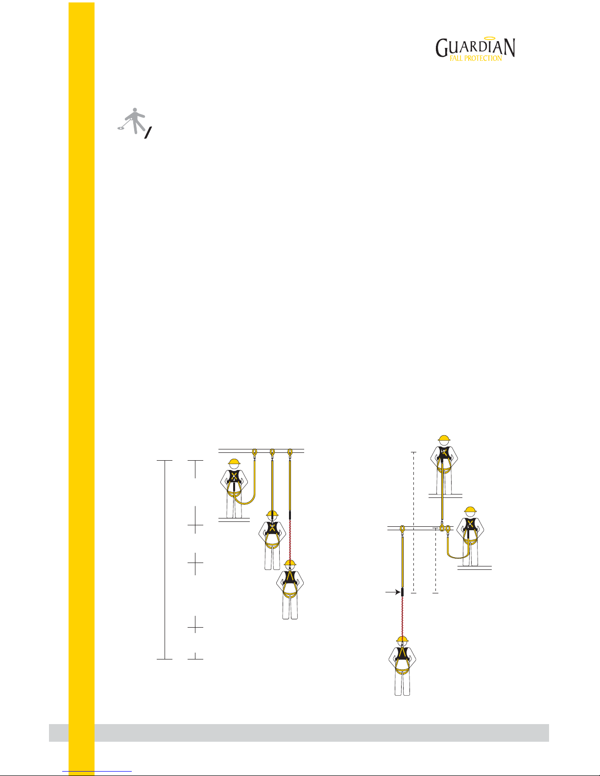
FALL CLEARANCE CALCULATION
Potential
free fall
(6’ total)
Safety factor
(3’ total)
Deceleration
distance (4’ total)
Height of harness
dorsal D-ring from
worker’s feet
(6’ total)
Required
distance
from
anchorage
(16’ total)
Limitations
Fall Clearance: There must be sufficient clearance below the anchorage connector to arrest a fall before the
user strikes the ground or an obstruction. When calculating fall clearance, account for a MINIMUM 3’ safety
factor, deceleration distance, user height, length of lanyard/SRL, and all other applicable factors.
Diagram shown is an example fall clearance calculation ONLY.
Swing Falls: Prior to installation or use, make considerations for eliminating or minimizing all swing fall
hazards. Swing falls occur when the anchor is not directly above the location where a fall occurs. Always work
as close to in line with the anchor point as possible. Swing falls significantly increase the likelihood of serious
injury or death in the event of a fall.
Compatibility: When making connections with VLA, eliminate all possibility of roll-out. Roll-out occurs when
interference between a hook and the attachment point causes the hook gate to unintentionally open and
release. All connections must be selected and deemed compatible with VLA by a Competent Person. All
connector gates must be self-closing and self-locking, and withstand minimum loads of 3,600 lbs. See the
following for examples of compatible/incompatible connections:
Anchor point
Free fall ends/
deceleration
begins
6’
free
fall
12’
free
fall
Max 48”
Deceleration
Standard 6’
lanyard shown
FREE FALL CALCULATION
Dorsal
D-ring
level with
anchor
Dorsal
D-ring
6’ above
anchor
Page 4

Guardian Fall Protection 6305 S. 231st St., Kent, WA 98032 USA phone: (800) 466-6385 fax: (800) 670-7892 www.guardianfall.com
3
Materials: steel, polyester or nylon, and steel polyolefin components.
Lifeline diameter: 5/8”.
Average arrest force: 900 lbs.
Maximum arrest force: 1,800 lbs.
Maximum elongation: 48”.
Shock Pack
Snap Hooks
Fall Arrester and
Extension Lanyard
(Rope Grab)
Rope Lifeline
Part # Length Description
01310
01320
25’
50’
Vertical Lifeline Assembly w/Shock Absorber, Positioning Device, & 18” Lanyard Extension
01323
01324
01325
75’
100’
130’
01326
01327 200’
150’
11318
11320 50’
30’
Vertical Lifeline Assembly w/Shock Absorber, Positioning Device, & 18” Lanyard Extension
Vertical Lifeline Assembly w/Shock Absorber, Positioning Device, & 18” Lanyard Extension
Vertical Lifeline Assembly w/Shock Absorber, Positioning Device, & 18” Lanyard Extension
Vertical Lifeline Assembly w/Shock Absorber, Positioning Device, & 18” Lanyard Extension
Vertical Lifeline Assembly w/Shock Absorber, Positioning Device, & 18” Lanyard Extension
Vertical Lifeline Assembly w/Shock Absorber, Positioning Device, & 18” Lanyard Extension
No Tangle VLA w/Swivel Snap Hook, Shock Absorber, Positioning Device, & 18” Lanyard Extension
No Tangle VLA w/Swivel Snap Hook, Shock Absorber, Positioning Device, & 18” Lanyard Extension
11329
11330
11331
11332
11333
11334
25’
30’
50’
75’
100’
150’
Polydac Rope w/Snap Hook End
Polydac Rope w/Snap Hook End
Polydac Rope w/Snap Hook End
Polydac Rope w/Snap Hook End
Polydac Rope w/Snap Hook End
Polydac Rope w/Snap Hook End
Components and Specifications
Connector
closed and
locked to
D-ring. OK.
Two or more
snap hooks or
carabiners
connected to
each other. NO.
Two connectors
to same
D-ring. NO.
Connector
directly to
horizontal
lifeline. NO.
Connector
to integral
lanyard.
NO.
Connector
directly to
webbing.
NO.
Application
that places
load on gate.
NO.
Incompatible
or irregular
application,
which may
increase risk
of roll-out. NO.
Page 5

Installation and Use
Guardian Fall Protection 6305 S. 231st St., Kent, WA 98032 USA phone: (800) 466-6385 fax: (800) 670-7892 www.guardianfall.com
4
1. Eliminate all risk of lower end termination. Either ensure VLA will prevent user from striking next lower
level and that there is always adequate fall clearance, or that VLA will not reach the leading edge of any fall
hazard when used at its full length. NEVER tie knots in lifeline, except at extreme bottom of lifeline in order to
prevent Fall Arrester from detaching.
2. Eliminate or minimize all risk of swing fall.
3. If VLA has integral Shock Pack, attach Shock Pack end to compatible anchorage connector.
4. Attach Fall Arrester and Extension Lanyard to applicable harness D-ring.
5. To move along lifeline, compress and hold Fall Arrester handle.
ALWAYS adjust Fall Arrester to reduce slack in the system as much
as possible. When attached to Fall Arrester and moving along work
surface, ALWAYS do so by moving Fall Arrester along rope, and
NEVER by moving only the rope itself. For example, if moving from
a roof edge to the roof peak, engage handle of Fall Arrester and
move it up the VLA while walking to peak. DO NOT move up to
roof peak by moving VLA and keeping Fall Arrester stationary;
doing so can create free fall in excess of levels permitted by system.
6. To restrict Fall Arrester movement along lifeline, release Fall
Arrester handle.
7. NEVER grab the Fall Arrester in the event of a fall; doing so may
cause the unit to accidentally disengage and slip along the rope.
Compress
to move
Release
to stop
01330
01340
25’
50’
Standard 5/8” Rope w/Snap Hook End
01350
01360
01365
75’
100’
150’
01345 200’
Standard 5/8” Rope w/Snap Hook End
Standard 5/8” Rope w/Snap Hook End
Standard 5/8” Rope w/Snap Hook End
Standard 5/8” Rope w/Snap Hook End
Standard 5/8” Rope w/Snap Hook End
11335
11321
11322
11323
11324
11325
11326
11327
11328
25’
30’
50’
75’
100’
130’
150’
200’
VLA w/3 Strand Polydac Rope, Shock Pack, Positioning Device, & 18” Lanyard Extension
VLA w/3 Strand Polydac Rope, Shock Pack, Positioning Device, & 18” Lanyard Extension
VLA w/3 Strand Polydac Rope, Shock Pack, Positioning Device, & 18” Lanyard Extension
VLA w/3 Strand Polydac Rope, Shock Pack, Positioning Device, & 18” Lanyard Extension
VLA w/3 Strand Polydac Rope, Shock Pack, Positioning Device, & 18” Lanyard Extension
VLA w/3 Strand Polydac Rope, Shock Pack, Positioning Device, & 18” Lanyard Extension
VLA w/3 Strand Polydac Rope, Shock Pack, Positioning Device, & 18” Lanyard Extension
VLA w/3 Strand Polydac Rope, Shock Pack, Positioning Device, & 18” Lanyard Extension
200’ Polydac Rope w/Snap Hook End
Part # Length Description
!
WARNING
One connection per VLA.
NEVER attempt to remove components from VLA.
Page 6

Maintenance, Cleaning, and Storage
If VLA fails inspection in any way, immediately remove it from service, and contact Guardian to inquire about
its return or repair.
Cleaning after use is important for maintaining the safety and longevity of VLAs. Remove all dirt, corrosives,
and contaminants from VLAs before and after each use. If a VLA cannot be cleaned with plain water, use mild
soap and water, then rinse and wipe dry. NEVER clean VLAs with corrosive substances.
When not in use, store equipment where it will not be affected by heat, light, excessive moisture, chemicals,
or other degrading elements.
Prior to EACH use, inspect VLA for deficiencies, including, but not limited to, corrosion, deformation, pits, burrs,
rough surfaces, sharp edges, cracking, rust, paint buildup, excessive heating, alteration, broken stitching,
fraying, bird-caging, and missing or illegible labels. IMMEDIATELY remove VLA from service if defects or
damage are found, or if exposed to forces of fall arrest.
Ensure that applicable work area is free of all damage, including, but not limited to, debris, rot, rust, decay,
cracking, and hazardous materials. Ensure that selected work area will support the application-specific
minimum loads set forth in this instruction manual. Work area MUST be stable.
At least every 6 months, a Competent Person other than the user must inspect VLAs. Competent Person
inspections MUST be recorded in inspection log in instruction manual and on equipment inspection grid
label. The Competent Person must sign their initials in the box corresponding to the month and year
the inspection took place.
During inspection, consider all applications and hazards VLAs have been subjected to.
Inspection
If equipment fails inspection IMMEDIATELY REMOVE FROM SERVICE.
Guardian Fall Protection 6305 S. 231st St., Kent, WA 98032 USA phone: (800) 466-6385 fax: (800) 670-7892 www.guardianfall.com
5
Inspection Log
Date of First Use: __________________.
Product lifetime is indefinite as long as it passes pre-use and Competent Person inspections. User must
inspect prior to EACH use. Competent Person other than user must complete formal inspection at least
every 6 months. Competent Person to inspect and initial.
This inspection log must be specific to one VLA. Separate inspection logs must be used for each VLA. All
inspection records must be made visible and available to all users at all times.
Page 7

Guardian Fall Protection 6305 S. 231st St., Kent, WA 98032 USA phone: (800) 466-6385 fax: (800) 670-7892 www.guardianfall.com
6
Safety Information
Failure to understand and comply with safety regulations may result in
serious injury or death. Regulations included herein are not all-inclusive,
are for reference only, and are not intended to replace a Competent
Person’s judgment or knowledge of federal or state standards.
!
WARNING
Do not alter equipment. Do not misuse equipment.
Workplace conditions, including, but not limited to, flame, corrosive chemicals, electrical shock, sharp objects,
machinery, abrasive substances, weather conditions, and uneven surfaces, must be assessed by a Competent
Person before fall protection equipment is selected.
The analysis of the workplace must anticipate where workers will be performing their duties, the routes they
will take to reach their work, and the potential and existing fall hazards they may be exposed to. Fall
protection equipment must be chosen by a Competent Person. Selections must account for all potential
hazardous workplace conditions. All fall protection equipment should be purchased new and in an unused
condition.
Fall protection systems must be selected and installed under the supervision of a Competent Person, and used
in a compliant manner. Fall protection systems must be designed in a manner compliant with all federal, state,
and safety regulations. Forces applied to anchors must be calculated by a Competent Person.
Harnesses and connectors selected must be compliant with manufacturer’s instructions, and must be of
compatible size and configuration. Snap hooks, carabiners, and other connectors must be selected and applied
in a compatible fashion. All risk of disengagement must be eliminated. All snap hooks and carabiners must be
self-locking and self-closing, and must never be connected to each other.
A pre-planned rescue procedure in the case of a fall is required. The rescue plan must be project-specific. The
rescue plan must allow for employees to rescue themselves, or provide an alternative means for their prompt
rescue. Store rescue equipment in an easily accessible and clearly marked area.
Training of Authorized Persons to correctly erect, disassemble, inspect, maintain, store, and use equipment
must be provided by a Competent Person. Training must include the ability to recognize fall hazards, minimize
the likelihood of fall hazards, and the correct use of personal fall arrest systems.
NEVER use fall protection equipment of any kind to hang, lift, support, or hoist tools or equipment, unless
explicitly certified for such use.
Equipment subjected to forces of fall arrest must immediately be removed from use.
Age, fitness, and health conditions can seriously affect the worker should a fall occur. Consult a doctor if there
is any reason to doubt a user’s ability to withstand and safely absorb fall arrest forces or perform set-up of
equipment. Pregnant women and minors must not use this equipment.
Physical harm may still occur even if fall safety equipment functions correctly. Sustained post-fall suspension
may result in serious injury or death. Use trauma relief straps to reduce the effects of suspension trauma.
Page 8

Labels
Guardian Fall Protection 6305 S. 231st St., Kent, WA 98032 USA phone: (800) 466-6385 fax: (800) 670-7892 www.guardianfall.com
7
Shock Pack Labels
(depending on model, may be beneath cover)
Lifeline Labels (double-sided)
85044 (Rev. G)
Serial #:
90120
(Rev. C )
Part #:
Length:
DOM:
ALWAYS READ AND UNDERSTAND ALL MANUFACTURER’S
INSTRUCTIONS INCLUDED WITH EQUIPMENT AT TIME OF SHIPMENT.
Make only compatible connections.
Refer to instructions for proper connection methods.
Worker weight capacity range: 130-310 lbs.
Compliant with all OSHA 1910, OSHA 1926 Subpart M,
ANSI Z359.1-07, and ANSI A10.32-12 regulations.
Materials: 5/8” diameter polysteel, polyester, or nylon.
Avoid contact with sharp and abrasive edges and surfaces.
DO NOT remove labels.
Warning: User Capacity Range 130-310 lbs.
900 lbs.
Forces may increase when cold and/or wet
Read Instructions Before Use
Maximum Free Fall Average Arresting Force
6ft.
Maximum Deployment Distance 48”
User must inspect prior to each use. Competent Person to inspect and initial at least
every 6 months. Date of First Use: ____________. Product lifetime is indefinite, as
long as product passes all inspection requirements.
 Loading...