

Guardian 004988-4 Owner's Manual
Owner’s Manual
Liquid-cooled, Prepackaged
Standby Generators
Model Number: 004988-4
27kW NG, 30kW LP Vapor
This manual should remain with the unit.
ONLY QUALIFIED ELECTRICIANS OR CONTRACTORS
SHOULD ATTEMPT INSTALLATION!!
INTRODUCTION
Thank you for purchasing this model of the standby
generator set.
Every effort was expended to make sure that the
information and instructions in this manual are both
accurate and current at the time the manual was written. However, the manufacturer reserves the right to
change, alter or otherwise improve this product(s) at
any time without prior notice.
READ THIS MANUAL THOROUGHLY
If any portion of this manual is not understood, contact the nearest Authorized Service Dealer for starting, operating and servicing procedures.
Throughout this publication, and on tags and
decals affixed to the generator, DANGER, WARNING,
CAUTION and NOTE blocks are used to alert personnel to special instructions about a particular service
or operation that may be hazardous if performed
incorrectly or carelessly. Observe them carefully. Their
definitions are as follows:
DANGER
After this heading, read instructions that, if not
strictly complied with, will result in personal injury
or property damage.
The operator is responsible for proper and safe use
of the equipment. The manufacturer strongly recommends that the operator read this Owner's Manual
and thoroughly understand all instructions before
using this equipment. The manufacturer also strongly recommends instructing other users to properly
start and operate the unit. This prepares them if they
need to operate the equipment in an emergency.
OPERATION AND MAINTENANCE
It is the operator's responsibility to perform all safety
checks, to make sure that all maintenance for safe
operation is performed promptly, and to have the
equipment checked periodically by an Authorized
Service Dealer. Normal maintenance service and
replacement of parts are the responsibility of the
owner/operator and, as such, are not considered
defects in materials or workmanship within the terms
of the warranty. Individual operating habits and usage
contribute to the need for maintenance service.
Proper maintenance and care of the generator ensures
a minimum number of problems and keep operating
expenses at a minimum. See the Authorized Service
Dealer for service aids and accessories.
Operating instructions presented in this manual
assume that the standby electric system has been
installed by an Authorized Service Dealer or other
competent, qualified contractor. Installation of this
equipment is not a “do-it-yourself” project.
After this heading, read instructions that, if not
strictly complied with, may result in personal injury
or property damage.
After this heading, read instructions that, if not
strictly complied with, could result in damage to
equipment and/or property.
NOTE:
After this heading, read explanatory statements
that require special emphasis.
These safety warnings cannot eliminate the hazards
that they indicate. Common sense and strict compliance with the special instructions while performing the
service are essential to preventing accidents.
Four commonly used safety symbols accompany the
DANGER, WARNING and CAUTION blocks. The type
of information each indicates is as follows:
This symbol points out important safety informa-
tion that, if not followed, could endanger personal
safety and/or property of others.
This symbol points out potential explosion hazard.
This symbol points out potential fire hazard.
This symbol points out potential electrical shock
hazard.
HOW TO OBTAIN SERVICE
When the generator requires servicing or repairs,
contact an Authorized Service Dealer for assistance.
Service technicians are factory-trained and are capable of handling all service needs.
When contacting an Authorized Service Dealer about
parts and service, always supply the complete model
number of the unit as given on the front cover of this
manual or on the DATA LABEL affixed to the unit.
AUTHORIZED SERVICE
DEALER LOCATION
To locate the nearest AUTHORIZED
SERVICE DEALER, please call this number:
1-800-333-1322
OR
Locate us on the web at:
www.generac.com
2

Table of Contents
Liquid-cooled 30 kW Generators
INTRODUCTION ............................................... IFC
SAFETY RULES ....................................................2
Section 1 — GENERAL INFORMATION ............. 4
1.1 Generator ..............................................................4
1.2 Transfer Switch .....................................................4
1.3 Automatic System Operation .................................4
1.4 Generator AC Connection Systems ........................4
1.5 Main Circuit Breaker .............................................4
1.6 Generator Fuel System ..........................................5
1.7 Engine Protective Devices ......................................5
1.8 Unpacking .............................................................6
1.9 Lifting the Generator .............................................6
1.10 Specifications ........................................................7
1.11 Fuel Consumption .................................................7
1.12 Reconfiguring the Fuel System ..............................7
1.13 Torque Specifications ............................................8
1.14 Engine Oil Recommendations ...............................8
1.15 Coolant Recommendations ....................................8
1.16 Before Installation .................................................8
Section 2 — INSTALLATION ............................. 8
2.1 Standby Generator Installation .............................8
2.2 Generator Location ...............................................9
2.3 Generator Mounting and Support .........................9
2.4 Basic Standby Electric System ..............................9
2.5 Emergency Circuit Isolation Method ...................10
2.6 Total Circuit Isolation Method .............................10
2.7 Grounding the Generator ....................................10
2.8 Generator AC Neutral Connections .....................10
2.9 Transfer Switch Start Signal Connections ...........10
2.10 Battery Installation ..............................................11
2.11 Preparation Before Start-Up ................................11
Section 3 — OPERATION ................................ 12
3.1 Using a Standard “GTS” Transfer Switch ...........12
3.2 Control Console Components ..............................13
3.3 Manual Transfer and Startup ..............................14
3.4 Engine Governor Adjustments ............................14
3.5 Retransfer and Shutdown ...................................14
3.6 Automatic Operation ...........................................14
3.7 Weekly Exercise Cycle .........................................15
Section 4 — MAINTENANCE ........................... 15
4.1 Maintenance Performed by Authorized
Service Facilities ..................................................15
4.2 Cooling System....................................................15
4.3 Overload Protection for Engine DC
Electrical System .................................................16
4.4 Checking Fluid Levels .........................................16
4.5 Maintenance Owner/Operator
Can Perform ........................................................16
4.6 Miscellaneous Maintenance .................................18
4.7 Scheduled Maintenance .......................................20
Section 5 — TROUBLESHOOTING ................. 23
Section 6 — NOTES ........................................ 24
Section 7 — INTALLATION DIAGRAM ............ 25
Section 8 — ELECTRICAL DATA .................... 26
Section 9 — EXPLODED VIEWS AND
PARTS LISTS ............................. 30
Section 10 — WARRANTY .................Back Cover
1
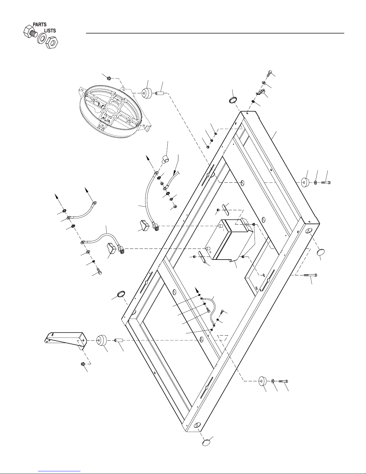
Section 9 - Exploded Views and Parts
Liquid-cooled 30 kW Generators
Mounting Base — Drawing No. 0E6266-F
TO
BLOCK
ENGINE
18
33
REAR BEARING
CARRIER
STARTER
BOLT
TO
18
2
3
4
10
16
14
11
12
14
1
MOUNTING BASE
5
6
7
TO
STARTER
13
37
HARNESS
CONTACTOR
20
15
WIRE
21
31
20
42
22
32
44
38
ENGINE
FOOT
36
35
34
41
39
44
TO
BLOCK
ENGINE
43
16
30
8
40
16
18
35
17
9
13
12
4
3
2
7
6
5
30
16

Section 9 - Exploded Views and Parts
Liquid-cooled 30 kW Generators
Mounting Base — Drawing No. 0E6266-F
ITEM PART NO. QTY. DESCRIPTION
1 0E5822 1 BASEFRAME, WELDMENT 3.0L FORD
2 052860 4 NUT FLANGED HEX M12-1.75
3 052251 4 DAMPENER VIBRATION 40 BLUE
4 052257 4 SPACER .49 X .62 X 1.87 PWDR/ZNC
5 052252 4 DAMPENER VIBRATION
6 052259 4 WASHER FLAT M12
7 052891 4 SCREW HHC M12-1.75 X 80 G8.8
8 0536210213 1 ASSY GRNDWIRE 11"/3/8 & 5/16 LUG
9 074906 1 SCREW HHTT M6-1.0 X 20 BP
10 047411 1 SCREW HHC M6-1.0 X 16 BP
11 055414 1 LUG SLDLSS #2-#8 X 17/64 CU
12 026850 2 WASHER SHAKEPROOF EXT 1/4 STL
13 022097 1 WASHER LOCK M6-1/4
14 022473 2 WASHER FLAT M6-1/4 ZINC
15 049813 1 NUT HEX M6 -1.0 G8 YEL CHR
16 0A1694 4 1-1/2" BUTTON PLUG
17 052213 1 SCREW HHC M10-1.25 X 20 G8.8
18 025507 3 WASHER SHAKEPROOF EXT 7/16 STL
20 027482 2 WASHER SHAKEPROOF EXT 5/16 STL
21 022129 1 WASHER LOCK M8-5/16
22 045771 1 NUT HEX M8-1.25 G8 YEL CHR
23 * 051756 1 SCREW HHC M10-1.5 X 20 G8.8
24 * 046526 1 WASHER LOCK M10
25 * 022131 1 WASHER FLAT 3/8-M10 ZINC
26 * 055934M 1 CLAMP VINYL .75 X .343 Z
30 077483 REF. BATT 12VDC 75-AH 26
058665 REF. BATT 12VDC 90-AH 27F
31 038804D 1 CABLE BATT RED #4 X 20.00
32 038805AA 1 CABLE BATT BLK #4 X 30"
33 021991 1 EARTH STRAP
34 049814 1 SCREW HHC M10-1.5 X 25 G8.8
35 046526 2 WASHER LOCK M10
36 022131 1 WASHER FLAT 3/8 ZINC
37 075763 1 BOOT BATTERY CABLE
38 050331 1 BATTERY POST COVER BACLK 39 050331A 1 BATTERY POST COVER RED +
40 0A4010 2 SCREW HHC M8-1.25 X 60 G8.8 FT
41 052858 2 NUT TOP LOCK FL M8-1.25
42 061902 1 HOLD DOWN BATTERY
43 059473 1 HOLD DOWN BATTERY
44 049820 2 NUT HEX LOCK M8-1.25 NY INS
* NOT SHOWN-USED TO HOLD DOWN I/N 32
31
S
O
S
O
S
S
O
S
O
S
C
C
C
O
OO
Q
CU
S
S
O
OR
O
T
9
)
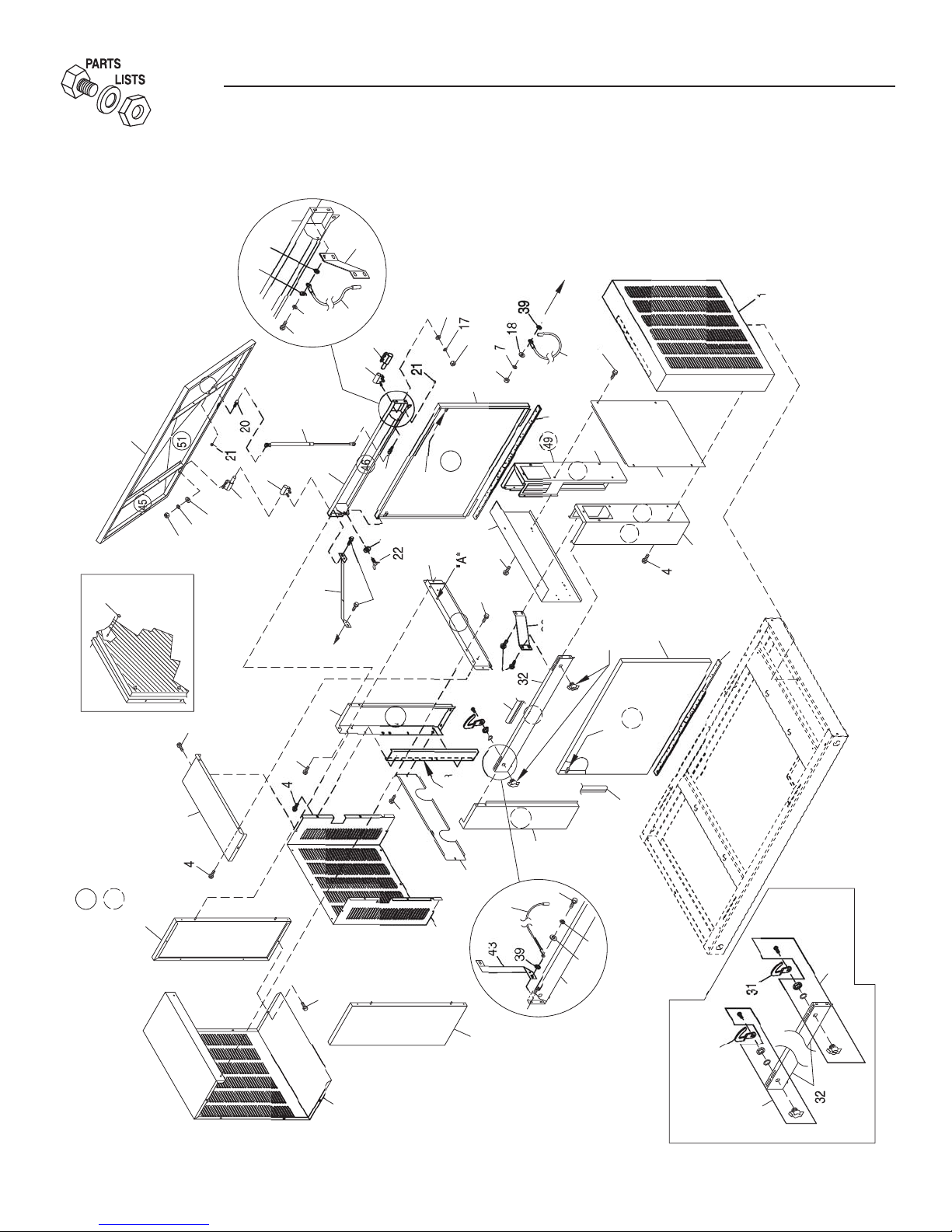
Section 9 - Exploded Views and Parts
Liquid-cooled 30 kW Generators
Enclosure — Drawing No. 0F1142-B
"B"
2-PLCS
IDE
N NEAR
AM I
F
TATE
IDE
N FAR
AM I
F
TATE
F PANEL THAT
WN.
H
F R
AL
RE A
UIRE INSULATION.
E
E
YPI
0
"A"
2
"
2
H
EE LAT
2
"
R
PP
ADIAT
7
32
4
2
1
H DETAIL
AT
 Loading...