

Page 1
Read This Instruction Manual Carefully Before Using This Equipment.
User Instructions must always be available to the user and are not to be removed except by the user of this equipment. For proper use, see
supervisor, User Instructions, or contact the manufacturer.
Compliant fall protection and emergency rescue systems help prevent serious injury during fall arrest. Users and purchasers of this equipment must read and understand the User Instructions provided for correct use and care of this product. All users of this equipment must
understand the instructions, operation, limitations and consequences of improper use of this equipment and be properly trained prior to
use per OSHA 29 CFR 1910.66 and 1926.503 or applicable local standards. Misuse or failure to follow warnings and instructions may result
in serious personal injury or death.
PURPOSE
The
00235
is an anchorage connector designed to function as an interface between the anchorage and a fall protection, work positioning,
rope access, or rescue system for the purpose of coupling the system to the anchorage. Any references to “anchorage connector” in this
manual include, and apply to, the
00235
.
USE INSTRUCTIONS
1. Before using a personal fall arrest system, user must be trained in accordance with the requirements of OSHA 29 CFR
1910.66 in the safe use of the system and its components.
2. Use only with ANSI/OSHA compliant personal fall arrest or restraint systems. The anchorage must have the strength capable
of supporting a static load, applied in the directions permitted by the system, of at least 5,000-lbf (22.2 kN) in the absence of
certication.
3. Use of this product must be approved by an Engineer or other qualied person to be compatible with any and all structural
& operational characteristics of the selected installation location and system to be connected to this anchorage connector.
Improper use may result in serious personal injury or death.
4. The anchorage connector must be inspected prior to each use for wear, damage, and other deterioration. If defective
components are found the anchorage connector must be immediately removed from service, in accordance with the
Requirements of OSHA 29 CFR 1910.66 and 1926.502.
5. The complete fall protection system must be planned (including all components, calculating fall clearance, and swing fall)
before using.
6. A rescue plan, and the means at hand to implement it, must be in place that provides the prompt rescue of users in the
event of a fall, or assures that users are able to rescue themselves.
7. After a fall occurs the anchorage connector must be removed from service and destroyed immediately.
USE LIMITATIONS
1. The anchorage connector is designed for a single user, with a capacity up to 310 lbs (140 kg) user including clothing, tools,
etc.
2. The anchorage connector is designed to be used in temperatures ranging from -40ºF to +130ºF (-40°C to +54°C).
3. Do not expose the anchorage connector to chemicals or harsh solutions which may have a harmful eect.
4. Do not alter or modify this product in anyway.
5. Caution must be taken when using any component of a fall protection, work positioning, rope access, or rescue system near
moving machinery, electrical hazards, sharp edges, or abrasive surfaces, as contact may cause equipment failure, personal
injury, or death.
6. Do not use/install equipment without proper training by a “competent person” as defined by OSHA 29 CFR 1926.32(f).
7. Do not remove the labeling from this product.
8. Additional requirements and limitations may apply depending on anchorage type and fastening option utilized for
installation. All placements must be approved by an engineer or other qualied person. Improper use may result in serious
personal injury or death.
9. This anchorage connector should not be used as part of a horizontal lifeline system that has not been designed and or
approved to be used with 5,000-lbf anchorage connectors.
COMPATIBILITY LIMITATIONS
The anchorage connector must only be coupled to compatible connectors. OSHA 29 CFR 1926.502 prohibits snaphooks from being
engaged to certain objects unless two requirements are met: it must be a locking type snaphook, and it must be “designed for” making such
a connection. “Designed for” means that the manufacturer of the snaphook specifically designed the snaphook to be used to connect to
the equipment listed. The following connections must be avoided, because they can result in rollout* when a nonlocking snaphook is used:
• Direct connection of a snaphook to horizontal lifeline.
• Two (or more) snaphooks connected to one D-ring.
• Two snaphooks connected to each other.
• A snaphook connected back on its integral lanyard.
• A snaphook connected to a webbing loop or webbing lanyard.
• Improper dimensions of the D-ring, rebar, or other connection point in relation to the snaphook dimensions that would allow the
snaphook keeper to be depressed by a turning motion of the snaphook.
*Rollout: A process by which a snaphook or carabiner unintentionally disengages from another connector or object to which it is
coupled. (ANSI Z359.1-2007)
MAINTENANCE, CLEANING AND STORAGE
Cleaning periodically will prolong the life and proper functioning of the product. The frequency of cleaning should be determined by
inspection and by severity of the environment. Clean with compressed air and/or a sti brush using plain water or a mild soap and water
solution. Do not use any corrosive chemicals that could damage the product. Wipe all surfaces with a clean dry cloth and hang to dry, or use
compressed air. When not in use, store anchorage connectors in a cool, dry, clean environment, out of direct sunlight and free of corrosive
or other degrading elements.
WARNING
IMPORTANT!!!
ALL PERSONS USING THIS EQUIPMENT MUST READ AND UNDERSTAND ALL INSTRUCTIONS.
FAILURE TO DO SO MAY RESULT IN SERIOUS INJURY OR DEATH. USERS SHOULD BE FAMILIAR
WITH PERTINENT REGULATIONS GOVERNING THIS EQUIPMENT. ALL INDIVIDUALS WHO USE
THIS PRODUCT MUST BE PROPERLY INSTRUCTED ON HOW TO USE THIS DEVICE.
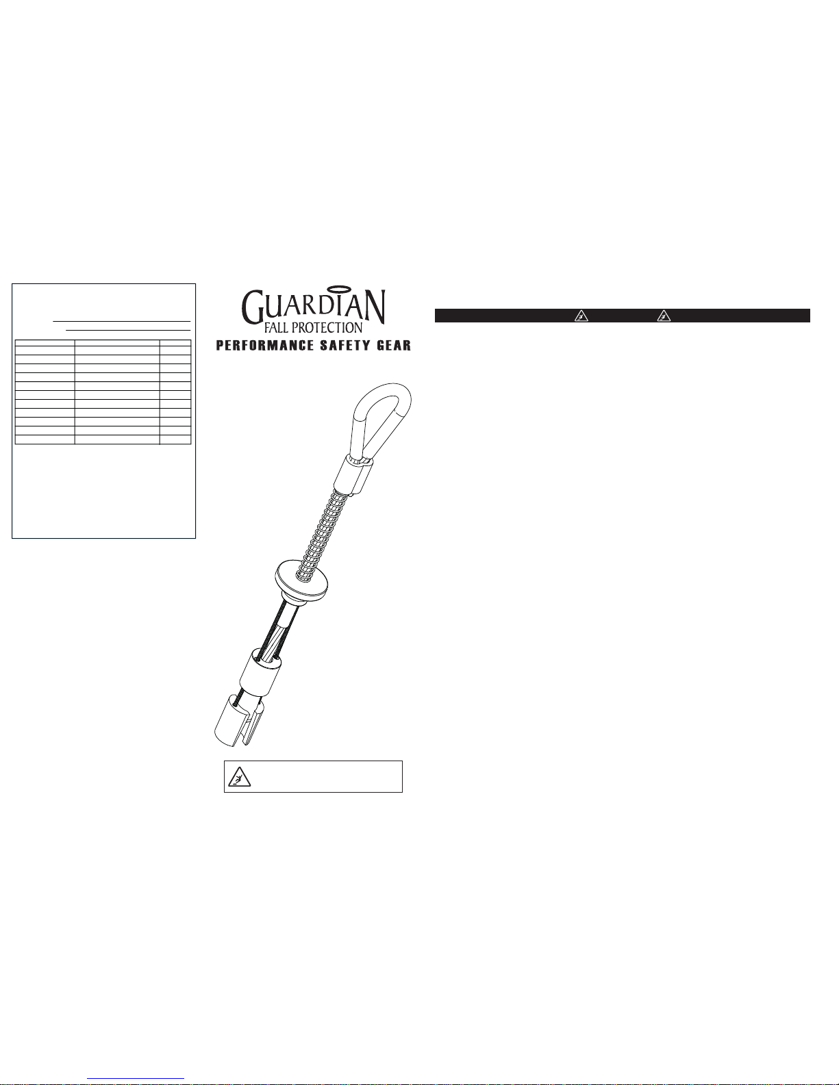
3/4” Reusable Bolt Anchor
5,000-lbf / 22kN
Model: 00235
Assembled in the USA
V1.4
Part Number
Inspection:
Ocial periodic inspection must be made at least annually. The inspection must be
performed by a qualied person other than the intended user. If severe weather or
conditions exist then inspections must be carried out more frequently. All inspection
results must be logged in the space provided above.
1. Inspect unit for visible signs of damage or wear that could aect operation. For
example: kinked or frayed cables.
2. Make sure all labeling is axed to the unit.
3. Check spoons and end termination operate smoothly with no metal burrs.
4. When reusing a previously drilled hole, inspect for debris or wallowing.
5. Record inspection results in the space provide above.
*If any damage that could aect the strength or operation of the device, or
unsafe conditions are found, proper disposal is required. The anchorage
connector must be rendered unusable and then properly discarded.
Comments
INSPECTION AND MAINTENANCE LOG
MODEL NUMBER:
DATE OF MANUFACTURE:
Inspector Name
Product Warranty, Limited Remedy and Limitation of Liability
WARRANTY: THE FOLLOWING IS MADE IN LIEU OF ALL WARRANTIES
OR CONDITIONS, EXPRESS OR IMPLIED, INCLUDING THE IMPLIED
WARRANTIES OR CONDITIONS OF MERCHANTABILITY OR FITNESS
FOR A PARTICULAR PURPOSE. Equipment oered by Guardian Fall
Protection is warranted against factory defects in workmanship and
materials for a period of one year from date of purchase.
LIMITED REMEDY: Upon notice in writing, Guardian Fall Protection will
repair or replace all defective items at Guardian Fall Protection’s sole
discretion. Guardian Fall Protection reserves the right to require that the
defective item be returned to its plant for inspection before determining
the appropriate course action. Warranty does not cover equipment
damage resulting from wear, abuse, damage in transit, failure to
maintain the product or other damage beyond the control of Guardian
Fall Protection. Guardian Fall Protection shall be the sole judge of
product condition and warranty options. This warranty applies only to
original purchaser and is the only warranty applicable to this product.
Please contact Guardian Fall Protection technical service department
for assistance.
LIMITATION OF LIABILITY: IN NO EVENT WILL GUARDIAN FALL
PROTECTION BE LIABLE FOR ANY INDIRECT, INCIDENTAL, SPECIAL
OR CONSEQUENTIAL DAMAGES INCLUDING, BUT NOT LIMITED TO
LOSS OF PROFITS, IN ANY WAY RELATED TO THE PRODUCTS
REGARDLESS OF THE LEGAL THEORY ASSERTED.
Guardian, LLC.
6305 South 231st St
Kent, WA 98032
1.800.466.6385. / www.guardianfall.com
Page 2
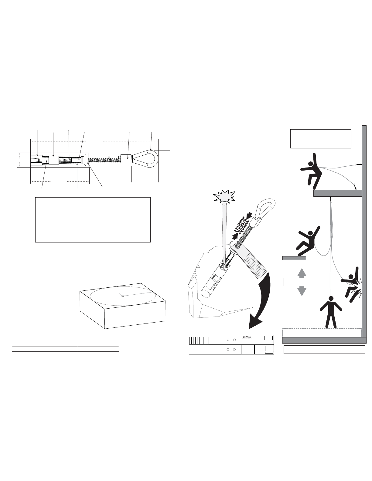
DRILLING & INSTALLATION INSTRUCTIONS:
1. Drill a 3/4” (19mm) diameter hole at least 3.5” (89mm) deep. The drilled hole must be straight and perpendicular
to the surface. Make sure the hole is of uniform diameter and free of peaks and valleys on the inner wall.
2. Blow hole clean with compressed air.
3. Always inspect the hole carefully when reusing a previously drilled hole.
4. When placing anchor, place your thumb inside the anchor loop and your rst two ngers around the trigger.
Squeeze ngers and thumb together till the trigger and spring fully compress.
5. Insert unit at least 3” (76mm) deep into hole and release the trigger. (Do not force.)
6. Set the unit with a slight tug on the anchor loop.
7. The stop sleeve must always be partially inserted into the hole.
All products subjected to fall arresting forces should be removed
from service immediately!
DECK/FLOOR/GROUND LEVEL
WORK SURFACE
(ANCHOR POINT)
MINIMUM CLEARANCE 3ft (1m)
WARNING!!! SWING FALLS CAN OCCUR WHEN THE WORKER IS NOT DIRECTLY UNDER ANCHOR POINT.
Free fall distance (limit) must
not exceed 6’ (1.8 m).
The concrete must be
3000-psi or higher and
fully cured. Installation
location to be approved
by a qualied person.
Spoon
Cleaning Bushing
Spring
Swage
Anchor Loop
Heavy Duty Return Wire
Stop Sleeve
End Termination
Trigger
1.25” (31mm)
3.0” (76mm)
7.0” (178mm)
11.5” (293mm)
Main Cable
2” (50.8mm)
REMOVAL INSTRUCTIONS:
1. When removing anchor, place your thumb inside the anchor loop
and your rst two ngers around the trigger. Squeeze ngers and
thumb together till the trigger and spring fully compress.
2. While squeezing the trigger pull the anchor out of the hole.
3. If the anchor becomes stuck, insert a punch, screwdriver or other
object into the hole until it touches the top of the cleaning bushing.
4. Lightly tap with a hammer making sure the tool is touching the top
of the cleaning bushing while squeezing the trigger. (The cleaning
bushing should be easily visible at the edge of the hole).
5. If tool was required to remove the anchorage inspect thoroughly for
damage after removal. If damage is found remove from service and
destroy immediately.
WORK SURFACE
May be used as a anchoring point for a leading
edge restraint system. Examples are of optional
anchoring point locations. The use of two anchors
is not required for leading edge restraint systems
unless otherwise specied by the manufacturer.
OPTIONAL
(ANCHOR POINTS)
(A)”
drill 3/4ӯ
min from
a
n
y edge
(B)”
HOLE DRILLING REQUIREMENT CHART
(A)” Minimum distance from edge/corner (B)” Concrete thickness
6” in. (15.3 cm)
12” in. (30.5 cm)
12” in. (30.5 cm)
5” in. (12.7 cm)
V1.4
PERFORMANCE:
Static Tensile Strength: 5000-lbf (22kN)
Maximum Capacity: one worker with
max weight of 310-lbs when used as a
single point anchorage connector for
personal fall arrest or restraint system.
DIMENSIONS:
Weight: .44-lbs (200g)
Length: 11.5” (349mm)
Diameter .75 (19mm)
REGULATORY COMPLIANCE:
ANSI Z359.1-2007, ANSI Z359.7-2011
OSHA 1926.502, OSHA 1910.66,
CE 0321 / EN 795:1996 (+A1:2000) Class B
COMPONENT MATERIALS:
Aluminum: Trigger
Aircraft Cable: Main Cable, Activator Wire
Polyurethane: Loop Cover
Stainless Steel: Cone, Spoons, Stop Sleeve
Zinc Plated Steel: Spring
Zinc Plated Copper: Swage
TAP!!!
DO NOT REMOVE
WARNING LABEL!
Inspect before each use. In addition , a competent person must inspect at least annually
INSPECTION LOG
Date Initial
Compliance:
OSHA 1926,502 & 1910.66
ANSI Z359.1
Max capacity 400 lbs.
(ANSI Z359.1- 310 lbs)
G-Bolt
TM
1-800-466-6385
Model #
( ) -00235 (3/4” 5,000 lbs.)
( )- 00365 (3/4” 5,000 lbs.)
( )- 00236 (1” 10,000 lbs.)
(Breaking strength rating)
Do Not Remove Label
US Patent 6,729,821
US Patent 7,011,281
US Patent 7,357,363
Lot #
0 1 2 3 4 5 6 7 8 9
0 1 2 3 4 5 6 7 8 9
0 1 2 3 4 5 6 7 8 9
MFG. Date
M
Y
1 2 3 4 5 6
7 8 9 10 11 12
11 12 13 14 15
Made in the USA
WARNING DO NOT use in wet or uncured concrete.
Use in normal weight concrete with a compression
Strength at least 3,000 PSI (20.7 MPa) Use for Fall
Protection Only.
* Do not use with incompatible connectors.
* Avoid physical hazards suck as thermal, electrical
and chemical sources.
* Avoid contact with sharp edges and
Abrasive surfaces.
Warning:
All persons using this equipment must
read, understand and follow all
Instructions. Failure to do so may result in
serious injury or death.
Reference instruction manual supplied
with the product for proper installation
procedures.
Materials:
* Stainless steel
* Aluminum alloy
* Zinc plated copper
*7x19 aircraft cable
Inspec
t b
e
fo
re each us
e
. I
n
a
dditi
on
, a
compe
tent pe
r
son
must inspect
at
le
a
s
t a
nnually
INSPECTIO
N
LO
G
Date Initial
 Loading...