


Owner’s Manual and
Installation Instructions
Liquid-cooled Recreational Vehicle Generator
•Model: 004270-2 QUIETPACT™ 75D
This manual should remain with the unit.
INTRODUCTION
Thank you for purchasing this model of the QUIETPACT™ product line by Generac Power Systems, Inc. This model is designed and manufactured to supply electrical power for recreational vehicles.
READ THIS MANUAL THOROUGHLY
If any portion of this manual is not understood, contact the nearest Generac Authorized Service Dealer for starting, operating, and servicing procedures.
Throughout this publication, and on tags and decals affixed to the generator, DANGER, WARNING, CAUTION, and NOTE blocks are used to alert personnel to special instructions about a particular operation that may be hazardous if performed incorrectly or carelessly. Observe them carefully. Their definitions are as follows:

 DANGER
After this heading, read instructions that, if not strictly complied with, will result in personal injury or property damage.
After this heading, read instructions that, if not strictly complied with, may result in personal injury or property damage.
After this heading, read instructions that, if not strictly complied with, could result in damage to equipment and/or property.
NOTE:
After this heading, read explanatory statements that require special emphasis.
These safety warnings cannot eliminate the hazards that they indicate. Common sense and strict compliance with the special instructions while performing the service are essential for preventing accidents.
Four commonly used safety symbols accompany the Danger, Warning, and Caution blocks. Here are the types of information indicated by each symbol:
This symbol points out important safety infor- ! mation that, if not followed, could endanger
personal safety and/or property to self and others.
This symbol points out potential explosion hazard.
 This symbol points out potential fire hazard.
This symbol points out potential electrical shock hazard.
The operator (i.e., the driver) is responsible for the proper and safe use of the vehicle and its equipment, and for the safety of all vehicle occupants. Before using this equipment, we strongly recommend that the operator read this manual and thoroughly understand all instructions. We also strongly recommend instructing other occupants in the vehicle to properly start and operate the generator. This prepares them to operate the equipment in case of an emergency.
CONTENTS
This manual contains pertinent owner’s information, including warranty, electrical diagrams, exploded views, and lists of repair parts for generator model number 004270-2. In addition, the latter portion of this manual contains information necessary for the proper installation of these generators.
OPERATION AND MAINTENANCE
It is the operator's responsibility to perform all safety checks, to make sure that all maintenance for safe operation is performed promptly, and to have the equipment checked periodically by a Generac Authorized Service Dealer. Normal maintenance service and replacement of parts are the responsibilities of the owner/operator and, as such, are not considered defects in materials or workmanship within the terms of the warranty. Individual operating habits and usage contribute to the need for maintenance service.
Proper maintenance and care of the generator minimizes problems and operating expenses. See the Generac Authorized Service Dealer for service aids and accessories.
HOW TO OBTAIN SERVICE
When the generator requires servicing or repairs, simply contact a Generac Authorized Service Dealer for assistance. Service technicians are factory-trained and are capable of handling all service needs.
When contacting a Generac Authorized Service Dealer or the factory about parts and service, always supply the complete model number and serial number of the unit, as given on its data decal, which is located on the generator.
Model No. ____________ Serial No. ______________
AUTHORIZED SERVICE
DEALER LOCATION
To locate the nearest GENERAC AUTHORIZED
SERVICE DEALER, please call this number:
1-800-333-1322
ONLY DEALER LOCATION INFORMATION
CAN BE OBTAINED AT THIS NUMBER.
Generac® Power Systems, Inc.

Table of Contents
QUIETPACT™ 75D Recreational Vehicle Generator
Part I – Owner’s Manual
Introduction ...................................... |
Inside Front Cover |
|
Read This Manual Thoroughly .................................... |
|
IFC |
Contents ...................................................................... |
|
IFC |
Operation and Maintenance ........................................ |
|
IFC |
How to Obtain Service.................................................. |
|
IFC |
Authorized Service Dealer Locator Number |
....................IFC |
|
Safety Rules |
...................................................................... |
2 |
|
Section 1 – General ..................................Information |
4 |
||
1.1 |
Generator ............................................Identification |
4 |
|
1.2 |
Generator ............................................Applicability |
5 |
|
1.3 |
Safety........................................................................ |
|
5 |
1.4 |
Generator ............................AC Connection System |
5 |
|
1.5 |
Specifications .......................................................... |
5 |
|
|
1.5.1 ...................................... |
Fuel Requirements |
5 |
|
1.5.2 ...................................... |
Fuel Consumption |
6 |
|
1.5.3 ............................ |
Engine Oil Requirements |
6 |
|
1.5.4 ...................................................... |
Coolant |
6 |
|
1.5.5 ........................................................ |
Engine |
6 |
|
1.5.6 .................................................. |
Generator |
6 |
Section 2 – Operation .................................................... |
7 |
||
2.1 |
Generator Control Panel .......................................... |
7 |
|
|
2.1.1 |
Hourmeter .................................................. |
7 |
|
2.1.2 |
Start/Stop Switch........................................ |
7 |
|
2.1.3 |
Fuse ............................................................ |
7 |
|
2.1.4 |
Line Breaker .............................................. |
7 |
|
2.1.5 |
Preheat Switch............................................ |
7 |
2.2 |
Optional Remote Start/Stop .................................... |
7 |
|
2.3 |
Before Starting the Engine........................................ |
7 |
|
|
2.3.1 |
Installation .................................................... |
7 |
|
2.3.2 |
Engine Lubrication........................................ |
8 |
|
2.3.3 |
Fuel Supply .................................................. |
8 |
|
2.3.4 |
Coolant Level ................................................ |
8 |
|
2.3.5 |
Cooling and Ventilating Air .......................... |
8 |
|
2.3.6 |
Engine Exhaust Gas...................................... |
8 |
2.4 |
Starting the Generator.............................................. |
8 |
|
2.5 |
Stopping the Generator ............................................ |
9 |
|
2.6 |
Applying Loads to Generator .................................... |
9 |
|
|
2.6.1 Letting the Engine Stabilize ........................ |
9 |
|
|
2.6.2 Do Not Overload the Generator .................. |
9 |
|
2.7 |
Protection Systems .................................................. |
9 |
|
|
2.7.1 Low Oil Pressure Switch ............................ |
9 |
|
|
2.7.2 High Coolant Temperature Switch .............. |
9 |
|
|
2.7.3 |
Overspeed Shutdown................................ |
10 |
|
2.7.4 |
Overvoltage Protection .............................. |
10 |
2.8 |
Additional Information .......................................... |
10 |
|
|
2.8.1 |
25-Hour Break-in Period .......................... |
10 |
|
2.8.2 |
25-Hour Check-up .................................... |
10 |
|
2.8.3 Attention Required After Submersion ...... |
10 |
|
|
2.8.4 Operation in High Grass or Brush............ |
11 |
|
|
2.8.5 Effects of Moisture and Dirt .................... |
11 |
|
Section 3 – Maintenance.............................................. |
11 |
||
3.1 |
Checking the Engine Oil Level ................................ |
11 |
|
3.2 |
Changing the Engine Oil and/or Oil Filter .............. |
11 |
|
3.3 |
Servicing the Engine Air Filter................................ |
12 |
|
3.4 |
Spark Arrestor Muffler .......................................... |
12 |
|
3.5 |
Cleaning the Generator .......................................... |
13 |
|
3.6 |
Battery Maintenance .............................................. |
13 |
|
3.7 |
Cooling System ...................................................... |
14 |
|
3.8 |
Engine Coolant ...................................................... |
14 |
|
3.9 |
Major Service Manual ............................................ |
14 |
|
3.10 |
Drive Belt .............................................................. |
14 |
|
3.11 |
Exercising the Generator ........................................ |
14 |
|
3.12 |
Out-of-Service Procedure ........................................ |
15 |
|
|
3.12.1 |
Removal From Service .............................. |
15 |
|
3.12.2 |
Return to Service ...................................... |
15 |
3.13 |
Service Schedule .................................................... |
16 |
|
Part II – Installation Instructions
Safety Rules .................................................................... |
18 |
||
Section 1 – General Information................................ |
20 |
||
1.1 |
Purpose and Scope of the Manual .......................... |
20 |
|
1.2 |
Safety |
...................................................................... |
20 |
1.3 |
Standards ................................................Booklets |
20 |
|
1.4 |
Equipment ..........................................Description |
20 |
|
1.5 |
Generator ........................Engine Operating Speed |
20 |
|
1.6 |
Generator ..........................AC Connection System |
20 |
|
Section 2 – ................................................Installation |
22 |
||
2.1 |
Location ............................................and Support |
22 |
|
|
2.1.1 .................................. |
Generator Location |
22 |
|
2.1.2 .................................. |
Generator Support |
22 |
|
2.1.3 ................................ |
Suspended Mounting |
22 |
|
2.1.4 .................................. |
Generator Restraint |
23 |
2.2 |
Generator ......................................Compartments |
23 |
|
|
2.2.1 ...................... |
Compartment Construction |
23 |
|
2.2.2 ...................... |
Sound Insulating Materials |
24 |
|
2.2.3 .................................................. |
Acoustics |
24 |
|
2.2.4 .................... |
Compartment Floor Cutouts |
25 |
2.3 |
Cooling ....................................and Ventilating Air |
26 |
|
|
2.3.1 .................................... |
Generator Airflow |
26 |
|
2.3.2 ........................Cooling Air Inlet Openings |
26 |
|
|
2.3.3 .................. |
Compensating for Restrictions |
27 |
|
2.3.4 .............................. |
Testing the Installation |
27 |
2.4 |
Diesel ..................................................Fuel System |
27 |
|
|
2.4.1 ................................................. |
Fuel Tank |
28 |
|
2.4.2 ....................Generator Fuel Supply Lines |
28 |
|
|
2.4.3 ....................Generator Fuel Return Lines |
28 |
|
2.5 |
Exhaust ......................................................System |
29 |
|
|
2.5.1 ......................Muffler and Spark Arrestor |
29 |
|
|
2.5.2 .............................. |
Exhaust System Safety |
29 |
2.6 |
Electrical ............................................Connections |
30 |
|
|
2.6.1 ............................ |
Electrical Junction Box |
30 |
|
2.6.2 ...................................................... |
Wiring |
30 |
|
2.6.3 ...................... |
Generator AC Connections |
30 |
|
2.6.4 .................................................... |
Conduit |
32 |
|
2.6.5 .................................. |
Power Supply Cord |
32 |
|
2.6.6 ............Ground Fault Circuit Interrupters |
32 |
|
|
2.6.7 ............Isolating Different Power Sources |
32 |
|
2.7 |
Battery ................................................Installation |
33 |
|
|
2.7.1 .............................. |
Recommended Battery |
33 |
|
2.7.2 .......................................... |
Battery Cables |
33 |
|
2.7.3 ........................ |
Battery Cable Connections |
33 |
|
2.7.4 .............................. |
Battery Compartment |
34 |
2.8 |
Optional ..............................................Accessories |
34 |
|
|
2.8.1 ................ |
Remote Start/Stop Connections |
34 |
Section 3 – Post-installation Startup |
35 |
||
|
......................................................... |
Checks |
|
3.1 |
Post Installation ............................................Tests |
35 |
|
3.2 |
Before ..............................................Initial Startup |
35 |
|
3.3 |
Initial ............................................................Start |
35 |
|
3.4 |
Testing ................................................Under Load |
35 |
|
3.5 |
Installation ..............................................Checklist |
36 |
|
Appendix 1 ....................................– Troubleshooting |
37 |
||
Appendix 2 ........................................................- Notes |
38 |
||
Appendix 3 ......................................– Electrical Data |
40 |
||
Appendix 4 ......– Exploded Views and Parts Lists |
44 |
||
Appendix 5 ......................................................– Notes |
63 |
||
Appendix 6 ................................................– Warranty |
64 |
||
Generac® Power Systems, Inc. 1
Safety Rules
QUIETPACT™ 75D Recreational Vehicle Generator
SAVE THESE INSTRUCTIONS – The manufacturer suggests that these rules for safe
!operation be copied and posted in potential hazard areas of the recreational vehicle. ! Safety should be stressed to all operators and potential operators of this equipment.
!WARNING: !
The engine exhaust from this product contains chemicals known to the state
of California to cause cancer, birth defects, or other reproductive harm.
! |
WARNING: |
! |
|
|
|
|
This product contains or emits chemicals |
|
|
known to the state of California to cause |
|
cancer, birth defects or other reproductive harm. |
||
Study these SAFETY RULES carefully before installing, operating, or servicing this equipment. Become familiar with this manual and with the unit. The generator can operate safely, efficiently, and reliably only if it is properly installed, operated, and maintained. Many accidents are caused by failing to follow simple and fundamental rules or precautions.
Generac cannot possibly anticipate every possible cir cumstance that might involve a hazard. The warnings in this manual, and on tags and decals affixed to the unit, are, therefore, not all-inclusive. If using a procedure, work method, or operating technique that Generac does not specifically recommend, ensure that it is safe for others. Also make sure the procedure, work method, or operating technique chosen does not render the generator unsafe.

 DANGER
Despite the safe design of this generator,
!operating this equipment imprudently, neglecting its maintenance, or being careless can cause possible injury or death. Permit only responsible and capable persons to operate and maintain this equipment.
Parts of the generator are rotating and/or hot
!during operation. Exercise care near running generators.
Potentially lethal voltages are generated by these machines. Ensure all steps are taken to render the machine safe before attempting to work on the generator.
! GENERAL HAZARDS !
• For safety reasons, Generac recommends that the installation, initial startup, and maintenance of this equipment be performed by a Generac Authorized Service Dealer.
•The generator engine releases DEADLY carbon monoxide gas through its exhaust system. This dangerous gas, if breathed in sufficient concentrations, can cause unconsciousness or even death. Never operate the generator set with the vehicle inside any garage or other enclosed area. DO NOT OPERATE THE GENERATOR IF THE EXHAUST SYSTEM IS LEAKING OR HAS BEEN DAMAGED. SYMPTOMS OF CARBON MONOXIDE POISONING ARE (a) inability to think coherently, (b) nausea, (c) vomiting, (d) twitching muscles, (e) throbbing temples, (f) dizziness, (g) headaches, (h) weakness, and (i) sleepiness. IF EXPERIENCING ANY OF THESE SYMPTOMS, MOVE INTO FRESH AIR IMMEDIATELY. IF SYMPTOMS PERSIST, GET MEDICAL HELP. Shut down the generator and do not operate it until it has been inspected and repaired.
•Never sleep in the vehicle while the genset is running unless the vehicle has a working carbon monoxide detector. The exhaust system must be installed in accordance with the genset installation manual. Make sure there is ample fresh air when operating the genset in a confined area.
•The engine exhaust fumes contain carbon monoxide, which can be DEADLY. This dangerous gas, if breathed in sufficient concentrations, can cause unconsciousness or even death. Thus, the exhaust system must be installed properly, in strict compliance with applicable codes and standards. Following installation, do nothing that might render the system unsafe or in noncompliance with such codes and standards. The generator compartment must be completely vapor-sealed from the vehicle interior. There must be no possibility of exhaust fumes entering the vehicle interior. Never operate this equipment with a leaking or defective exhaust system.
•Keep hands, feet, clothing, etc., away from drive belts, fans, and other moving or hot parts. Never remove any drive belt or fan guard while the unit is operating.
•Adequate, unobstructed flow of cooling and ventilating air is critical to correct generator operation and is required to expel toxic fumes and fuel vapors from the generator compartment. Without sufficient cooling airflow, the engine/generator quickly overheats, which seriously damages the generator. Do not alter the installation or permit even partial blockage of ventilation provisions, as this can also seriously affect the safe operation of the generator.
2 Generac® Power Systems, Inc.

Safety Rules
QUIETPACT™ 75D Recreational Vehicle Generator
•When working on this equipment, remain alert at all times. Never work on the equipment when physically or mentally fatigued.
•Inspect the generator regularly, and contact the nearest Generac Authorized Service Dealer immediately for parts needing repair or replacement.
•Before performing any maintenance on the generator, disconnect its battery cables to prevent accidental startup. First, disconnect the cable from the battery post, indicated by a NEGATIVE, NEG, or
(–). Reconnect this cable last.
•Never use the generator, or any of its parts, as a step. Stepping on the unit can stress and break parts, resulting in dangerous operating conditions due to leaking exhaust gases, fuel leakage, oil leakage, etc.
•Never insert any tool or other object through openings in the generator interior, even if the unit is not running. Serious injury or damage to the equipment could be done.
 ELECTRICAL HAZARDS
•The generator covered by this manual produces dangerous electrical voltages and can cause fatal electrical shock. Avoid contact with bare wires, terminals, connections, etc., while the unit is running. Before operating the generator, ensure all appropriate covers, guards, and barriers are in place . If work must be done around an operating unit, stand on an insulated, dry surface to reduce shock hazard.
•Do not handle any kind of electrical device while standing in water, while barefoot, or while hands or feet are wet. DANGEROUS ELECTRICAL SHOCK MAY RESULT.
•During installation onto the vehicle, have the generator properly grounded (bonded), either by solid mounting to the vehicle frame or chassis, or by means of an approved bonding conductor. DO NOT disconnect the bonding conductor, if so equipped. DO NOT reconnect the bonding conductor to any generator part that might be removed or disassembled during routine maintenance. If the grounding conductor must be replaced, use only a flexible conductor that is of No. 8 American Wire Gauge (AWG) copper wire minimum.
•In case of an accident caused by electric shock, immediately shut down the source of electrical power. If this is not possible, attempt to free the victim from the live conductor. AVOID DIRECT CONTACT WITH THE VICTIM. Use a nonconducting implement, such as, a dry rope or board, to free the victim from the live conductor. If the victim is unconscious, apply first aid and get immediate medical help.
•Never wear jewelry when working on this equipment. Jewelry can conduct electricity, resulting in electric shock, or may get caught in moving components, causing, injury.
 FIRE HAZARDS
•For fire safety, the generator must be installed and maintained properly. Installation must always comply with NFPA 70 (latest edition), “National Electrical Code”, Article 551, and NFPA 1192 (latest edition), “Standard for Recreational Vehicles”, along with all applicable codes, standards, laws, and regulations. Adhere strictly to local, state, and federal electrical and building codes. Comply with regulations the Occupational Safety and Health Administration (OSHA) has established. Also, ensure that the generator is installed in accordance with the manufacturer’s instructions and recommendations. After proper installation, do nothing that might alter the installation and render the unit in noncompliance with the aforementioned codes, standards, laws, and regulations.
•Keep a fire extinguisher in the vehicle at all times. Extinguishers rated “ABC” by the National Fire Protection Association are appropriate for use on the recreational vehicle generator electrical system. Keep the extinguisher properly charged and be familiar with its use. If there are any questions pertaining to fire extinguishers, consult the local fire department.
 EXPLOSION HAZARDS
•Do not smoke around the generator. Wipe off any fuel or oil spills immediately. Ensure that no combustible material is left in the generator compartment, or on or near the generator, as FIRE or EXPLOSION may result. Keep the area surrounding the generator clean and free of debris.
•All fuel types are potentially FLAMMABLE and/or EXPLOSIVE and should be handled with care. Comply with all laws regulating the storage and handling of fuels. Inspect the unit’s fuel system frequently and correct any leaks immediately. Before placing this equipment into service, the fuel supply lines must be properly installed, purged, and leaktested according to applicable fuel-gas codes.
Generac® Power Systems, Inc. 3

Section 1 – General Information
QUIETPACT™ 75D Recreational Vehicle Generator
1.1GENERATOR IDENTIFICATION
Please record the following information from the generator DATA DECAL or information decal, located below the user control panel.
1. |
Model Number ____________________ |
2. |
Serial Number __________________ |
3. |
kW Rating__________________________ |
4. |
Rated Voltage __________________ |
Model: 04270-2
QUIETPACT™ 75D
1. 2-Pole, 35-amp Circuit
Breaker
2. Hourmeter
3. Oil Fill Opening and Plug
4. Oil Dipstick
5. Engine Start/Stop Switch
6. 14-amp Fuse
7. Engine Preheat Switch
8. Fuel Filter
9. Air Filter
10. Oil Filter
11. Starter Motor
12. Preheat Contactor
13. Starter Contactor
14. Radiator
15. Coolant Recovery Tank
16. Muffler
17. Battery Connections
18. Fuel Connections
19. Alternator
20. Fuel Pump
21. Centrifugal Cooling Fan
and Housing
22. Alternator Drive Belt
23. Alternator Drive Belt
Tensioner
24. Cooling Fan Drive Belt
25. Cooling Fan Drive Belt
Tensioner
26. Engine
4 Generac® Power Systems, Inc.
Section 1 – General Information
QUIETPACT™ 75D Recreational Vehicle Generator
1.2GENERATOR APPLICABILITY
These generators have been designed and manufactured for supplying electrical power to recreational vehicles. DO NOT modify the generator nor use it for any application other than for what it was designed. If there are any questions pertaining to its application, write or call the factory. Do not use the unit until advised by a competent authority.

 DANGER
For fire safety, the generator must have been properly installed in compliance with NFPA 70
(latest edition), “National Electrical Code”, Article 551, and NFPA 1192 (latest edition), “Standard for Recreational Vehicles”. The generator also must have been installed in strict compliance with the manufacturer’s detailed installation instructions. After installation, do nothing that might render the unit in noncompliance with such codes, standards, and instructions.
Use this generator to supply electrical power for operating 120/240-volt, single-phase, 60-Hertz, AC electrical loads. These loads can require up to 7,500 watts (7.5 kW) of power, but cannot exceed 62.5 AC amps of current at 120 volts, or 31.2 AC amps at 240 volts.
Do not overload the generator. Some installa-
!tions may require that electrical loads be alternated to avoid overloading. Applying excessively high electrical loads may damage the generator and shorten its life. Add up the rated watts of all electrical lighting, appliance, tool, and motor loads the generator will power at one time. This total should not be greater than the wattage capacity of the generator. If an electrical device nameplate gives only volts and amps, multiply volts times amps to obtain watts (volts x amps = watts). Some electric motors require more watts of power (or amps of current) for starting than for continuous operation.
1.3SAFETY
Before attempting to use the generator set, carefully read the “Safety Rules” section of this manual. Comply strictly with these rules to prevent accidents and damage to equipment and/or property. We suggest copying and posting the “Safety Rules” in potential hazard areas of the vehicle. Stress safety to all operators and potential operators of this equipment.
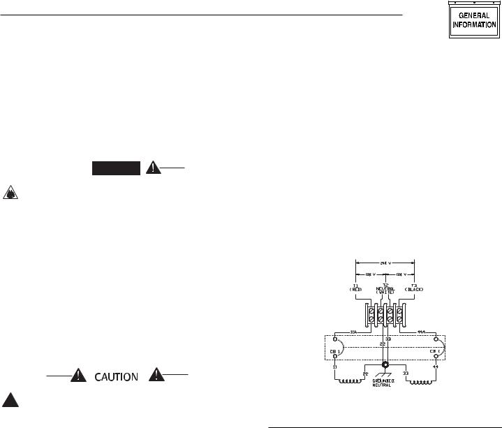
1.4GENERATOR AC
CONNECTION SYSTEM
This generator is equipped with dual-stator AC power windings. These two-stator windings supply electrical power to customer electrical loads by means of a dual, two-wire connection system. Note, however, that the neutral is grounded.
The generator may have been installed so that it powers 120and/or 240-volt AC electrical loads (Figure 1.1). It can be rewired to connect 120-volt AC electrical loads only. This procedure should be done by a Generac Authorized Service Dealer or other qualified installer. Refer to the installation portion of this manual for more information.
Figure 1.1 – Connections for 120/240 Dual Voltage
1.5SPECIFICATIONS
1.5.1 FUEL REQUIREMENTS
The generator is equipped with a diesel fuel system. Use clean, fresh No. 1D or No. 2D diesel fuel with minimum Cetane number of 40. The diesel fuel must also conform to American Society of Testing and Materials (ASTM) specifications. Never use any dirty or contaminated fuel. When adding fuel, DO NOT overfill the tank. Allow room at the top of the tank for fuel expansion. Depending on the installation, the generator may have either a separate fuel tank or “share” the vehicle’s engine fuel tank.
NOTE:
Some installations using a “shared” fuel tank may have a generator fuel pickup tube that is shorter than the vehicle’s engine pickup tube. Such an arrangement causes the generator engine to “run out of fuel”, while adequate fuel for the vehicle engine remains in the tank.
Also, appropriate care should be taken in applications where extremely low ambient temperatures are possible, to ensure the temperature of the diesel fuel is not allowed to fall below levels where “gelling” could occur
Generac® Power Systems, Inc. 5
Section 1 – General Information
QUIETPACT™ 75D Recreational Vehicle Generator
1.5.2 FUEL CONSUMPTION (GAL/HR)
Model |
No Load |
Half Load |
Full Load |
QUIETPACT™ 75D |
0.28 |
0.45 |
0.78 |
(004270-0) |
|
|
|
|
|
|
|
1.5.3 ENGINE OIL REQUIREMENTS
Use a high-quality detergent oil with American Petroleum Institute (API) classification “For Service CC.” Detergent oils keep the engine cleaner and reduce carbon deposits. Use oil having the following SAE viscosity rating, based on the ambient temperature range anticipated before the next oil change:
Temperature |
Oil Grade (Recommended) |
Above 100º F (38º C) |
SAE 15W-40* or SAE 40 |
40º to 100º F (4.4º to 38º C) |
SAE 10W-30 or SAE 30 |
Below 40º F (4.4º C) |
SAE 5W-20 or 5W-30 |
* - in units from the factory
Crankcase and oil filter capacity is approximately 3.5 L or 3.7 U.S. quarts. Do NOT use special additives. See Sections 3.1 and 3.2 for oil level checking and changing procedures.
1.5.4 COOLANT
Use a 50:50 mixture that is half low silicate, ethylene glycol base antifreeze and half soft water. Use only soft water and only low silicate antifreeze. If desired, a high-quality rust inhibitor to the recommended coolant mixture may be added. When adding coolant, always add the recommended 50-50 mixture.

 DANGER
Do not remove the radiator pressure cap while
!the engine is hot; otherwise, serious burns from boiling liquid or steam could result.
Ethylene glycol base antifreeze is poisonous.
!Do not use mouth to siphon coolant from the radiator, recovery bottle, or any container. Wash hands thoroughly after handling. Never store used antifreeze in an open container because animals are attracted to the smell and taste of antifreeze, even though it is poisonous to them.
Do not use any chromate base rust inhibitor
!with ethylene glycol base antifreeze; or else, chromium hydroxide (“green slime”) will form and cause overheating. Engines that have been operated with a chromate base rust inhibitor must be chemically cleaned before adding ethylene glycol base antifreeze. Using any high-sil- icate antifreeze boosters or additives will also cause overheating. DO NOT use any soluble oil inhibitor for this equipment.
1.5.5 ENGINE
Type of Engine .......................................................... |
|
ISM Diesel |
Cylinder Arrangement ................................................ |
|
3, in-line |
Displacement ................................................ |
|
58.2 in3. (954 cc) |
Bore ................................................................ |
|
2.95 in. (75 mm) |
Stroke ............................................................ |
|
2.83 in. (72 mm) |
Compression Ratio ........................................................ |
|
23-to-1 |
Combustion Chamber Type ............................ |
Pre-Combustion |
|
Rated Horsepower.......................................... |
|
13 @ 1,950 rpm |
Cylinder Block ............................................................ |
|
Cast Iron |
Number of Main Bearings........................................................ |
|
4 |
Number of Teeth on Flywheel.............................................. |
104 |
|
Type of Governor .............................. |
|
Mechanical, Fixed Speed |
Fuel Filter ............................ |
Full Flow Spin-On (Part # 69858) |
|
Oil Filter ........................................ |
|
Full Flow with Bypass Valve |
|
|
(Part # 126-70939) |
Oil Pressure ................................................................ |
|
29-71 psi |
Type of Cooling System.............. |
|
Pressurized, Closed Recovery |
Cooling Method.................................................... |
|
Liquid-cooled |
Type of Cooling Fan ...................................... |
|
Centrifugal Puller |
Cooling System Capacity .......................... |
|
1.4 U.S. gals (5.3 L) |
Air Cleaner............................ |
Disposable Filter (Part # C4880) |
|
Starter.......................................................... |
|
12-volt DC Electric |
Recommended Battery .................... |
|
70 Ah, 360 Cold-cranking |
|
|
Amps (Minimum ratings) |
Maximum Cranking Current .................................... |
220 Amps |
|
Ground Polarity ............................................................ |
|
Negative |
1.5.6 GENERATOR
Rated Maximum Continuous AC Output at ...
85º F (29º C) Ambient.......................... |
7,500 Watts (7.5 kW) |
100º F (38º C) Ambient ...................... |
7,000 Watts (7.0 kW) |
120º F (49º C) Ambient ...................... |
6,000 Watts (6.0 kW) |
Rated Voltage................................................ |
120/240 Volts AC* |
Rated Maximum Continuous AC Current at ... |
|
7,500 Watts |
|
120 Volts........................................................ |
62.5 Amps |
240 Volts........................................................ |
31.2 Amps |
7,000 Watts |
|
120 Volts........................................................ |
58.3 Amps |
240 Volts........................................................ |
29.2 Amps |
6,000 Watts |
|
120 Volts........................................................ |
50.0 Amps |
240 Volts........................................................ |
25.0 Amps |
Phase ................................................................................ |
Single |
Rotor Speed at No Load .......................................... |
3,780 rpm |
Number of Rotor Poles ............................................................ |
2 |
Engine RPM ...................................................................... |
1,950 |
Rated AC Frequency ........................................................ |
60 Hz |
Battery Charge Voltage............................................ |
14 Volts DC |
Battery Charge Current ...................................... |
2 Amps (max) |
Weight...................................................................... |
486 Pounds |
Length .................................................... |
36.6 inches (929 mm) |
Width...................................................... |
23.8 inches (604 mm) |
Height .................................................... |
22.3 inches (567 mm) |
*All units are reconnectable to 120-volt-only AC output.
6 Generac® Power Systems, Inc.
Section 2 – Operation
QUIETPACT™ 75D Recreational Vehicle Generator
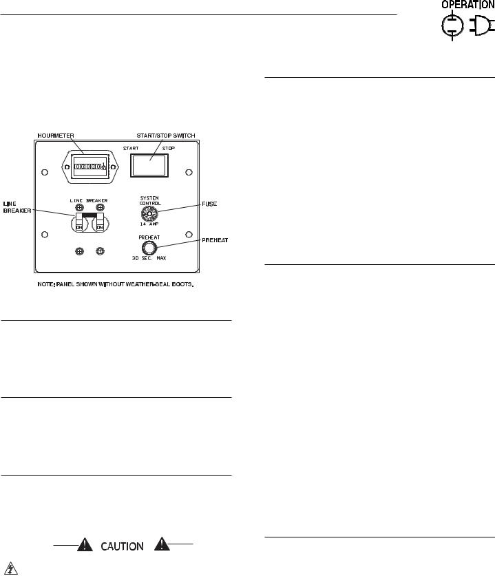
2.1GENERATOR CONTROL PANEL
The following features are mounted on the generator control panel (Figure 2.1):
Figure 2.1 – Generator Control Panel
2.1.1 HOURMETER
This indicates the length of time the engine/generator has operated, in hours and tenths of hours. Use the hourmeter to ensure that the periodic maintenance tasks for the generator are completed on a timely basis.
2.1.2 START/STOP SWITCH
To crank and start the engine, hold this switch in the START position. Release the switch when the engine starts. To stop an operating engine, press and hold the switch in the STOP position until the engine shuts off. The switch’s center position is the RUN position.
2.1.3 FUSE
The 14-amp fuse protects the engine’s DC control circuit against electrical overload. If the fuse element has melted open due to overloading, the engine cannot be cranked. If the fuse must be replaced, use only an identical replacement (i.e., SFE-14).
If a fuse element melts, find the cause of the overload before replacing the fuse.
2.1.4 LINE BREAKER
The line (i.e., main) breaker protects the generator’s AC output circuit against overload and provides a method of turning OFF the generator’s 120/240-volt AC output to the vehicle circuits. The QUIETPACT™ 75D has two 35-amp breakers.
NOTE:
Refer to Section 1.4, “Generator AC Connection System,”. Individual installations will differ. If an overload occurs, the dual breakers will open the ungrounded (i.e., hot) stator leads (11 and 44 in Figure 1.1). When the generator has been connected for 120 volts only (Figure 2.16, Page 31), the line breakers will operate independently on the ungrounded (i.e., hot) stator leads (11 and 33 in Figure 2.16, Page 31).
2.1.5 PREHEAT SWITCH
The diesel engine is equipped with glow plugs, one for each cylinder. When the preheat switch is pressed, the glow plugs heat the engine combustion chamber, allowing for quicker starts when the engine is cold. Pressing the preheat switch also operates the fuel pump.
2.2OPTIONAL REMOTE START/STOP
This generator is equipped with a plug-in connector that can be interfaced with an optional remote panel provided inside the vehicle. This option allows for starting and stopping the generator conveniently from within the vehicle. Refer to Part II - Installation Instructions, Section 2.8, for details on the remote start/stop option.
2.3BEFORE STARTING THE ENGINE
NOTE:
Instructions and information in this manual assume the generator has been properly installed, connected, serviced, tested and adjusted by a qualified installation technician or installation contractor.
2.3.1 INSTALLATION
Generator installation must have been properly completed so that it complies with all applicable codes, standards, and regulations and with the manufacturer's recommendations.
Generac® Power Systems, Inc. 7
Section 2 – Operation
QUIETPACT™ 75D Recreational Vehicle Generator
2.3.2 ENGINE LUBRICATION
Before starting the engine, have the engine crankcase properly serviced with the recommended oil. Refer to Section 1.5.3 and Sections 3.1 and 3.2 for oil servicing procedures and recommendations.
Any attempt to crank or start the engine before
!it has been properly serviced it with the recommended oil may result in an engine failure.
2.3.3 FUEL SUPPLY
The engine must have an adequate supply of proper fuel to operate. Before starting it, check that sufficient fuel is available.
NOTE:
Depending on the installation, the generator may have either a separate fuel tank or “share” the vehicle’s engine fuel tank.
Some installations using a “shared” fuel tank may have a generator fuel pickup tube that is shorter than the vehicle’s engine pickup tube. Such an arrangement causes the generator engine to “run out of fuel”, while adequate fuel for the vehicle engine remains in the tank.

 DANGER
The generator engine releases DEADLY carbon
!monoxide gas through its exhaust system. This dangerous gas, if breathed in sufficient concentrations, can cause unconsciousness or even death. Never operate the generator set with the vehicle inside any garage or other enclosed area. DO NOT OPERATE THE GENERATOR IF THE EXHAUST SYSTEM IS LEAKING OR HAS BEEN DAMAGED. SYMPTOMS OF CARBON MONOXIDE POISONING ARE (a) inability to think coherently, (b) nausea, (c) vomiting, (d) twitching muscles, (e) throbbing temples, (f) dizziness, (g) headaches, (h) weakness, and (i) sleepiness. IF EXPERIENCING ANY OF THESE SYMPTOMS, MOVE INTO FRESH AIR IMMEDIATELY. IF SYMPTOMS PERSIST, GET MEDICAL HELP. Shut down the generator and do not operate it until it has been inspected and repaired.

 DANGER
Never sleep in the vehicle while the genset is
!running unless the vehicle has a working carbon monoxide detector. The exhaust system must be installed in accordance with the genset installation manual. Make sure there is ample fresh air when operating the genset in a confined area.
2.3.4 COOLANT LEVEL
Check the engine coolant level prior to initial use and at recommended intervals. Refer to Section 1.5.4, “Coolant”, and Section 3.8, “Engine Coolant”, for procedures and recommendations.
2.3.5 COOLING AND VENTILATING AIR
Air inlet and outlet openings in the generator compartment must be open and unobstructed for continued proper operation. Without sufficient cooling and ventilating airflow, the engine/generator may overheat, causing engine shutdown and damage to the generator.
2.3.6 ENGINE EXHAUST GAS
Before starting the generator engine, be sure there is no way for exhaust gases to enter the vehicle interior and endanger people or animals. Close windows, doors, and other openings in the vehicle that, if open, might permit exhaust gases to enter the vehicle.
8 Generac® Power Systems, Inc.
2.4STARTING THE GENERATOR
NOTE:
Read the vehicle manufacturer’s instructions. The owner/operator should become familiar with the vehicle in which this generator is installed. Differences exist between vehicles. For example, some vehicles may use a transfer switch to isolate dockside power from the generator, while other vehicles may use an isolating receptacle. Some vehicles may be equipped with a DC converter, which allows the generator to power certain DC lighting and other DC loads.
To start the generator from either the generator control panel or from the optional remote panel, proceed as follows:
1.Turn OFF electrical loads using the means provided in the vehicle (such as, a main-line circuit breaker or transfer switch).
NOTE:
If starting from the generator control panel, turn OFF loads by setting the generator’s main-line breaker to the OFF (or open) position. If starting from a remote panel, turn OFF loads using the means provided in the vehicle (such as, a main circuit breaker). Electrical load circuits will be turned ON, after the generator has started, stabilized, and warmed up.
Section 2 – Operation
QUIETPACT™ 75D Recreational Vehicle Generator
2.If the engine is cold, press the Preheat switch for a maximum of 15 to 30 seconds.
3.While pressing the Preheat switch to crank the engine, hold the engine Start/Stop switch in the START position. When the engine starts, release the switches.
If the engine does not start after it has been
!cranking for 15 seconds, release the Start/Stop switch, wait 15 seconds, and try again. Holding the switch for longer than 15 seconds can damage the starter motor.
4.Let the engine run at no-load for a few minutes to stabilize and warm up.
5.Turn ON electrical loads, using the means provided in the vehicle (such as, a main-line circuit breaker or transfer switch).
2.5STOPPING THE GENERATOR
1.Turn OFF all electrical loads, using the means provided in the vehicle (such as, a main-line circuit breaker or transfer switch).
2.Let the generator run at no-load for a few minutes, to stabilize internal engine generator temperatures.
Do not stop the engine/generator immediately
!after running under load. This can overheat and damage the engine and/or generator.
3.Press and hold the Start/Stop switch in the STOP position, until the engine shuts off.
2.6APPLYING LOADS TO GENERATOR
When applying electrical loads to the generator, observe these guidelines:
•Before applying electrical loads, let the generator stabilize and warm up for a minute or two.
•DO NOT overload the generator.
2.6.2 DO NOT OVERLOAD THE GENERATOR
Read the rated wattage/amperage capacity of the generator on the generator data decal located below the user control panel.
Applying electrical loads in excess of the unit’s rated capacity may trip the line breaker or cause the engine/generator to shut down.
To avoid overloading, add up the wattage of all connected electrical lighting, appliance, tool, and motor loads. This total should not be greater than the generator’s rated wattage capacity.
•Most lighting, appliance, tool, and motor loads indicate their required watts on their nameplate or data plate. For light bulbs, simply note the wattage rating of the bulb.
•If a load does not show its rated wattage, multiply that load’s rated VOLTS times AMPS to obtain WATTS.
•Induction-type motors (such as, those that run the vehicle’s furnace fan, refrigerator, air conditioner, etc.) need about 2-1/2 time more watts of power for starting than for running (for a few seconds during motor starting). Be sure to allow for this when connecting electrical loads to the generator. First, calculate the watts needed to start electric motors in the system. To that figure, add the running wattages of other items that will be operated by the generator.
•For the first two or three hours of operation, do not apply electrical loads over 75 percent of the unit’s rating.
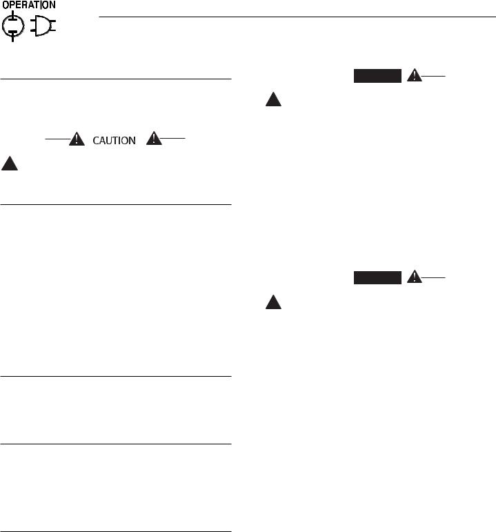
2.7PROTECTION SYSTEMS
The engine has several safety switches that cause it to automatically shut down, under the following conditions: low oil pressure, high coolant temperature, and engine overspeed. See Figure 2.2 for the location of these devices. If automatic shutdown does occur, refer to “Troubleshooting Guide”.
2.6.1 LETTING THE ENGINE STABILIZE
The generator supplies correctly rated voltage only at the proper governed speed. Some electrical appliances may be extremely sensitive to voltage. Incorrect voltages can damage such appliances.
Electrical loads applied on the engine at reduced operating speeds, such loads imposed on the engine, when sufficient power is not available, may shorten engine life. Never turn ON electrical loads until after the generator engine has started and stabilized at noload.
2.7.1 LOW OIL PRESSURE SWITCH
This switch is normally closed (N.C.) but is held open by engine oil pressure during engine running. Should operating oil pressure drop below approximately 10 psi, the switch contacts close, and the engine shuts down automatically.
2.7.2 HIGH COOLANT TEMPERATURE SWITCH
This normally-open (N.O.) thermostatic switch has a sensing tip that is immersed in captive coolant. Should the coolant temperature exceed approximately 115° C (240° F), the switch contacts close, and the engine shuts down automatically.
Generac® Power Systems, Inc. 9
Section 2 – Operation
QUIETPACT™ 75D Recreational Vehicle Generator
Figure 2.2 – Engine Protective Devices
2.7.3 OVERSPEED SHUTDOWN
A DC control circuit board senses engine speed from the frequency of the alternator AC output. Should the alternator output frequency exceed approximately 72 Hertz (4,320 alternator rpm), circuit board action initiates an automatic engine shutdown.
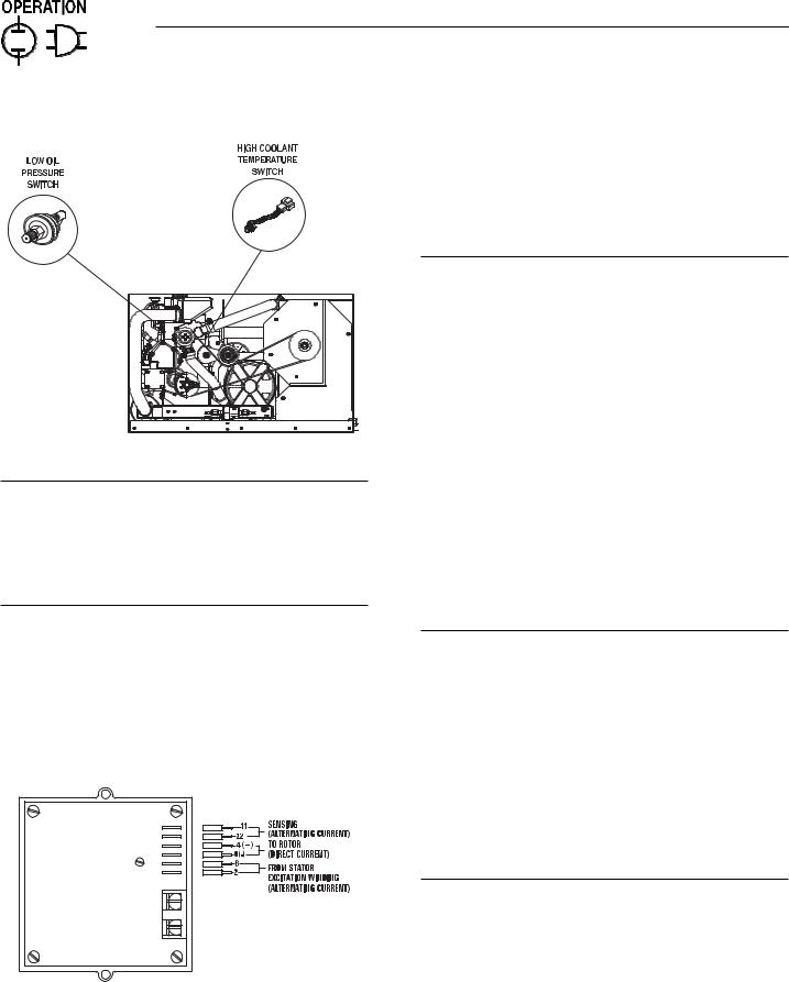
2.7.4 OVERVOLTAGE PROTECTION
A solid-state voltage regulator (Figure 2.3) controls the generator’s AC output voltage. This regulator supplies an excitation current to the rotor. By regulating the rotor’s excitation current, the strength of its magnetic field is regulated and, in turn, the voltage delivered to connected electrical loads is controlled. When the AC frequency is 60 Hertz, voltage is regulated at 120 volts (voltage-to-frequency ratio is 2-to-1).
Figure 2.3 – Solid-state Voltage Regulator
The voltage regulator also incorporates a “voltage surge protection circuit.” This circuit prevents troublesome surges in the generator AC output voltage. Voltage surge is a common cause of damage to electronic equipment.
2.8ADDITIONAL INFORMATION
2.8.1 25-HOUR BREAK-IN PERIOD
The first 25 hours of operation is the break-in period for the generator. Properly breaking in the generator is essential to minimize oil consumption and maximize engine performance. During this 25-hour break-in period, observe the following rules:
•Run the unit at varying electrical loads to help seat the engine piston rings properly.
•After operating the unit for 25 hours, complete the tasks recommended under Section 2.8.2.
•For the next 75 hours of operation, following the break-in period, avoid light electrical loads. Load the generator at 50 percent (or more) of its rated wattage capacity. Repeated light loads during these 75 hours can cause improper seating of engine piston rings, resulting in blowby and high oil consumption.
•Check the engine oil level frequently. Add oil if needed. It is normal for the generator engine to consume more oil than normally, until the piston rings have properly seated.
2.8.2 25-HOUR CHECK-UP
After the 25-hour break-in period, contact a Generac Authorized Service Dealer for the following maintenance, for which the vehicle owner is responsible for all charges:
•Change the engine crankcase oil and oil filter.
•Check all fluid levels (engine coolant, fuel, battery electrolyte fluid).
•Visually inspect the unit for any leaks or loose hardware.
•Inspect the exhaust tailpipe for any leaks or damage.
2.8.3 ATTENTION REQUIRED
AFTER SUBMERSION
If the recreational vehicle generator has been submerged in water, it MUST NOT be started and operated. Following any submersion in water, have a Generac Authorized Service Dealer thoroughly clean and dry the generator.
10 Generac® Power Systems, Inc.
Section 3 – Maintenance
QUIETPACT™ 75D Recreational Vehicle Generator
2.8.4 OPERATION IN HIGH GRASS OR BRUSH
Never operate the generator while the vehicle is parked over high grass, weeds, brush, leaves, or other combustible substance. Such materials can ignite and burn from the heat of the exhaust system. The generator exhaust system becomes extremely hot during operation and remains hot for a long time after it has shut down.
2.8.5 EFFECTS OF MOISTURE AND DIRT
Keep the generator set as clean and dry as possible. Protect the unit against excessive dust, dirt, corrosive vapors, road splash, etc. Permitting dirt and moisture to accumulate on generator windings will have an adverse effect on the insulation resistance of those windings.
When moisture is allowed to remain in contact with windings, some of the moisture will be retained in voids and cracks in the insulation. This reduces insulation resistance and will eventually cause problems. Dirt will make the problem worse, since it tends to hold moisture in contact with windings. Salt (as from sea air) will also worsen the problem, since it tends to absorb moisture from the air. Salt and moisture, when combined, form a good electrical conductor.
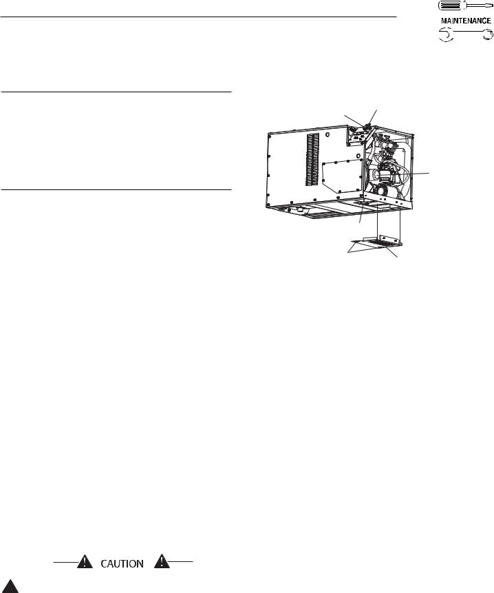
3.1CHECKING THE ENGINE OIL
LEVEL
After the 25-hour break-in period, check the engine crankcase oil level every eight hours of operation, or at least once daily, before using the generator. For oil capacities and requirements, see “Engine Oil Requirements,” Section 1.5.3. To check the engine oil level, proceed as follows (see Figure 3.1):
1.Be sure the generator is as leveled as possible.
2.Remove the dipstick, and wipe it dry with a clean, lint-free cloth.
3.Install the dipstick, and fully seat the T-handle; then, remove it again. The oil level should be at the dipstick “Full” mark.
4.If necessary, remove the oil fill plug and slowly add oil until it reaches the dipstick “FULL” mark. DO NOT FILL ABOVE THE “FULL” MARK.
Never operate the engine with the oil level
!below the “ADD” mark on the dipstick. Doing this could damage the engine.
5.Install the oil-fill plug and the dipstick before operating the engine.
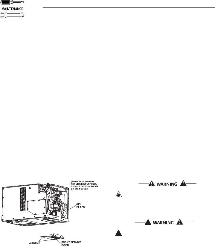
Figure 3.1 – Oil Maintenance Features
OIL FILL |
OIL DIPSTICK |
OPENING AND PLUG |
|
(PANEL TRANSPARENT FOR VIEWING PURPOSES. SERVICE THROUGH FRONT SERVICE DOOR.)
OIL
FILTER
OIL DRAIN
PLUG
LATCHES |
FRONT SERVICE |
|
DOOR |
3.2CHANGING THE ENGINE OIL
AND/OR OIL FILTER
Change the engine oil and oil filter after the first 25 hours of operation (after the 25-hour break-in period, see Section 2.8.1). See the “Service Schedule,” Section 3.13, for subsequent oil and filter changes. Change the oil more frequently, if operating consistently under heavy load or at high ambient temperatures.
To change the oil and/or oil filter, proceed as follows (see Figure 3.1):
1. Run the engine until it is thoroughly warmed up (for at least five minutes) then shut OFF the engine.
2.Immediately after the engine shuts OFF, remove the front service door, located beneath the unit, by retracting the two latches and pivoting the door downward.
3.Remove the air filter (see Section 3.3).
4.Remove the oil-drain plug and drain the oil into a suitable container. Removing the oil-fill plug will allow the crankcase to drain faster.
5.After the oil has drained, replace the oil-drain plug.
Go to step 9 if changing oil only.
6.With the oil drained, remove the old oil filter by turning it counterclockwise.
7.Apply a light coating of clean engine oil to the gasket of the new filter.
8.Screw the new filter on by hand, until its gasket lightly contacts the oil filter adapter. Then, tighten the filter an additional 3/4 to one turn.
Generac® Power Systems, Inc. 11
Section 3 – Maintenance
QUIETPACT™ 75D Recreational Vehicle Generator
9.Remove the dipstick, and wipe it dry with a clean, lint-free cloth. This will be used later to check the oil level.
10.Remove the oil-fill plug, and slowly add the proper type and amount of recommended oil (see Section 1.5.3). Periodically use the dipstick to check the oil level and continue to fill the crankcase until the oil reaches the dipstick “FULL” mark. DO NOT FILL ABOVE THE “FULL” MARK.
11.Install the oil-fill plug and the dipstick.
12.Reinstall the air filter.
13.Reattach the front service door; make sure the latches are fully engaged.
14.Start the engine, and check for leaks.
NOTE:
Check the oil level and fill to the “FULL” mark, after checking for leaks. The filter will retain some oil.
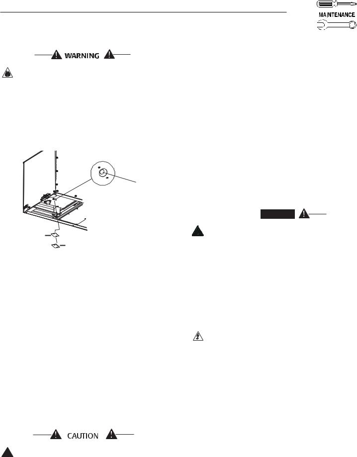
3.3SERVICING THE ENGINE
AIR FILTER
To access the engine air filter (Figure 3.2), remove the front service door, located beneath the unit, by retracting the two latches and pivoting the door downward. Loosen the hose clamp at the base of the air filter and remove the filter. Place the hose clamp on the new filter and install it, making sure it is positioned properly before reattaching the service door. Make sure the service door latches are fully engaged.
Figure 3.2 – Engine Air Filter
See the “Service Schedule,” Section 3.13, for recommended air cleaner maintenance.
3.4SPARK ARRESTOR MUFFLER
The exhaust muffler supplied with the QUIETPACT™ 75D is a spark arrestor type. Generac exhaust mufflers for recreational vehicle generators do not have a spark arrestor screen, but are of the more efficient “toroid” or “swirl” type. To remove carbon and combustion deposits from the muffler, proceed as follows (see Figure 3.3):
1.Place the unit above a noncombustable surface, and ensure that the generator exhaust piping is cool.
2.Remove the two screws holding the spark arrestor access plate to the rear floor pan.
3.Remove the spark arrestor access plate and gasket.
4.Remove the hex pipe cap from the end of the spark arrestor cleanout pipe.
5.Thread on a 3/8” NPT pipe coupling and pipe nipple to extend the cleanout pipe at least 10 inches (250 mm) below the rear floor pan; additional piping may be added to direct the muffler exhaust away from the cooling air discharge flow beneath the unit.
6.Start and run the engine for approximately 15 minutes.
7.Shut down the engine, and allow the piping to cool.
8.Remove the 3/8” NPT coupling and piping.
9.Apply a graphite-base, anti-seize compound to the cleanout pipe threads.
10.Reinstall the hex pipe cap, spark arrestor access plate, gasket, and two screws.
The exhaust system of this product gets extremely hot and remains hot after shutdown. High grass, weeds, brush, leaves, etc., must remain clear of the exhaust. Such materials may ignite and burn from the heat of the exhaust system.
Failure to provide and maintain a spark arrestor
!may be in violation of the law. If this generator is used on any forest-covered, brush-covered, or grass-covered unimproved land, the vehicle owner or operator must maintain the spark arrestor in good condition. In the state of California, the preceding is required by law (Section 4442 of the California Public Resources Code). Other states may have similar laws. Federal laws apply on federal lands.
12 Generac® Power Systems, Inc.
Section 3 – Maintenance
QUIETPACT™ 75D Recreational Vehicle Generator
Be sure to reinstall the hex pipe cap tightly to the spark arrestor cleanout pipe. Vibration could cause a loose cap to fall out, resulting in hot engine exhaust being drawn through the centrifugal cooling fan and out beneath the unit. This could result in damage to the generator or in discharge of hot exhaust sparks beneath the unit.
Figure 3.3 – Spark Arrestor
Muffler Maintenance
3/8" NPT HEX PIPE CAP
GASKET
ACCESS PLATE
3.5CLEANING THE GENERATOR
Keep the generator as clean and as dry as possible. Dirt and moisture that accumulate on internal generator windings have adversely affect insulation resistance.
Periodically, clean the generator’s exterior surfaces. A soft brush may be used to loosen caked-on dirt. Use a vacuum system or dry, low-pressure air to remove any accumulations of dirt. The generator is housed inside an all-weather enclosure; clean the enclosure with a soft, damp cloth or with sponge and water.
Once each year, have the generator cleaned and inspected by a Generac Authorized Service Dealer. Service technicians will use dry, low-pressure air to clean internal windings. Parts inside the control console should be cleaned and inspected at this time, as well.
Finally, have the insulation resistance of stator and rotor windings checked. If insulation resistances are excessively low, the generator may require drying.
Do NOT use a forceful spray of water to clean
!the generator. Water will enter the generator interior and cause problems, and may also contaminate the generator fuel system.
3.6BATTERY MAINTENANCE
All lead-acid batteries will discharge when not in use. The generator battery should be inspected per the “Service Schedule,” Section 3.13. The following procedure should be used for inspection:
•Inspect the battery posts and cables for tightness and corrosion. Tighten and clean as necessary.
•Check the battery fluid level of unsealed batteries and, if necessary, fill with Distilled Water Only. Do not use tap water in batteries.
•Have the state of charge and condition checked by a Generac Authorized Service Dealer.
NOTE:
Servicing of the battery is to be performed or supervised by knowledgeable personnel, according to the required precautions. Keep unauthorized personnel away from batteries.
Damage will result if the battery connections are made in reverse.

 DANGER
Do not dispose of the battery in a fire. The battery is capable of exploding. Storage batteries release explosive hydrogen gas. This gas can form an explosive mixture around the battery for several hours after charging. The slightest spark can ignite the gas and cause an explosion. Such an explosion can shatter the battery and cause blindness or other injury. Any area that houses a storage battery must be properly ventilated. Do not allow smoking, open flame, sparks, or any spark-producing tool or equipment near the battery. Discharge static electricity from body before touching the battery by first touching a grounded metal surface.
A battery presents a risk of electrical shock and high short-circuit current. The following precautions are to be observed when working on batteries:
•Remove watches, rings, and other metal objects;
•Use tools with insulated handles;
•Wear rubber gloves and boots;
•Do not lay tools or metal parts on top of the battery;
•Disconnect any charging source prior to connecting, or disconnecting, battery terminals; and
•Do not use any jumper cables or booster battery to crank and start the generator engine. If any battery has discharged, remove it for recharging.
Generac® Power Systems, Inc. 13
Section 3 – Maintenance
QUIETPACT™ 75D Recreational Vehicle Generator
Do not open or mutilate the battery. Released ! electrolyte has been known to be harmful to
the skin and eyes, and to be toxic.
The electrolyte is a dilute sulfuric acid that is ! harmful to the skin and eyes. It is electrically
conductive and corrosive. The following procedures are to be observed:
• Wear full eye protection and protective clothing;
• Immediately wash with water all skin areas that come into contact with the electrolyte.
• If the electrolyte contacts the eyes, immediately flush eyes thoroughly with water, and seek medical attention.
• Spilled electrolyte is to be washed down with an acid-neutralizing agent. A common practice is to use a solution of 1 pound (500 grams) bicarbonate of soda to 1 gallon (4 liters) of water. The bicarbonate of soda solution is to be added until the evidence of reaction (foaming) has ceased. The resulting liquid is to be flushed with water and the area dried.
3.7COOLING SYSTEM
Air intake and outlet openings in the generator compartment must be open and unobstructed for continued proper operation. Avoid obstructions, such as, high grass, weeds, brush, leaves, and snow.
Without sufficient cooling and ventilating air flow, the engine/generator quickly overheats, which causes it to shut down.
3.8ENGINE COOLANT
Check the coolant level in the coolant recovery tank at least once daily or prior to use. Add the recommended coolant mixture (see Section 1.5.4), as necessary; the tank should be kept within the levels indicated on the adjacent decal. If desired, a high-quality rust inhibitor to the recommended 50-50 coolant mixture may be added. If added consistently, the recommended mixture will protect the unit against freezing temperatures.
Periodically remove the radiator pressure cap, located behind the access cover above the user control panel, to make sure the coolant recovery system is functioning properly. Coolant should be at the bottom of the radiator filler neck. If the coolant level is low, inspect the gasket in the radiator pressure cap. Replace the cap, if necessary. To have the pressure cap tested, contact a Generac Authorized Service Dealer. Inspect both the cooling system and coolant recovery system for leaks.

 DANGER
Do not remove the radiator pressure cap while
!the engine is hot; otherwise, serious burns from boiling liquid or steam could result.
Ethylene glycol base antifreeze is poisonous.
!Do not use mouth to siphon coolant from the radiator, recovery bottle, or any container. Wash hands thoroughly after handling. Never store used antifreeze in an open container because animals are attracted to the smell and taste of antifreeze, even though it is poisonous to them.
Do not use any chromate base rust inhibitor
!with ethylene glycol base antifreeze; otherwise, chromium hydroxide (“green slime”) will form and cause overheating. Engines that have been operated with a chromate base rust inhibitor must be chemically cleaned before adding ethylene glycol base antifreeze. Using any high-silicate antifreeze boosters or additives will also cause overheating. DO NOT use any soluble oil inhibitor for this equipment.
3.9MAJOR SERVICE MANUAL
To obtain a service manual for the generator, the nearest Generac Authorized Service Dealer. Make sure to identify the MODEL NUMBER and SERIES.
3.10 DRIVE BELT
The engine drives the generator rotor by means of a pulley and drive belt arrangement. Drive belt tension was properly adjusted before the unit was shipped from the factory. If suspect that drive belt tension is incorrect, contact a Generac Authorized Service Dealer.
3.11 EXERCISING THE GENERATOR
At least once every seven days, start and operate the generator. Let the unit run for at least 30 minutes to “exercise” the engine. If the generator cannot be exercised every seven days, and it is to be out of service longer than 30 days, see Section 3.12.
14 Generac® Power Systems, Inc.
Section 3 – Maintenance
QUIETPACT™ 75D Recreational Vehicle Generator
3.12 OUT-OF-SERVICE PROCEDURE
3.12.1 REMOVAL FROM SERVICE
Prepare the generator for storage as follows:
1.Start the engine and let it run until it is thoroughly warmed up (at least five minutes), then shut off the engine.
2.While the engine is still warm from running, drain the oil completely (see Section 3.2). Refill the crankcase with the recommended oil (see Section 1.5.3).
3.Attach a tag to the engine, indicating the viscosity and classification of the oil in the crankcase.
4.Remove the battery and store it in a cool, dry room on a wooden board. Never store the battery on any concrete or earthen floor.
5.Clean and wipe the entire generator.
3.12.2 RETURN TO SERVICE
To return the unit to service after storage, proceed as follows:
1.Check the tag on the engine for oil viscosity and classification. Verify that the correct recommended oil is used in the engine (see Section 1.5.3). If necessary, drain and refill with the proper oil.
2.Check the state of the battery. Fill all cells of unsealed batteries to the proper level with distilled water. DO NOT USE TAP WATER IN THE BATTERY. Recharge the battery to 100 percent state of charge, or, if defective, replace the battery.
3.Clean and wipe the entire generator.
4.Reconnect the battery. Observe battery polarity. Damage may occur if the battery is connected incorrectly.
5.Turn OFF all electrical loads. Add fuel, if necessary, and then start the engine.
6.Allow the unit to warm up thoroughly.
7.Apply electrical loads to at least 50 percent of the unit’s rated wattage capacity.
8.When the engine is thoroughly warmed up, shut it down.
9.The generator is now ready for service.
Generac® Power Systems, Inc. 15

Section 3 – Maintenance
QUIETPACT™ 75D Recreational Vehicle Generator
3.13 SERVICE SCHEDULE
ATTENTION: It is recommended that all service work
be performed by the nearest Generac Authorized Service Dealer.
|
SYSTEM/COMPONENT |
|
PROCEDURE |
|
FREQUENCY |
|
|
|
X = Action |
Inspect |
Change |
Clean |
D = Daily |
W = Weekly |
|
|
R = Replace/Adjust as Needed |
|
|
|
M = Monthly |
Y = Yearly |
|
|
* = To Be Completed by a |
|
|
|
H = Hours |
|
|
|
Generac Authorized |
|
|
|
|
|
|
|
Service Dealer. |
|
|
|
|
|
|
|
FUEL |
|
|
|
|
|
|
|
Fuel level |
X |
|
|
AFTER 25-H BREAK-IN, |
|
|
|
|
|
|
|
D / BEFORE USE |
|
|
|
Fuel lines and connections* |
X |
|
|
AFTER 25-H BREAK-IN, |
|
|
|
|
|
|
|
EVERY 250 H / 6 M |
|
|
|
Fuel Filter* |
|
X |
|
EVERY 250 H / 6 M |
|
|
|
LUBRICATION |
|
|
|
|
|
|
|
Oil level |
X |
|
|
EVERY 8 H / D |
|
|
|
Oil |
|
X |
|
AFTER 25-H BREAK-IN, |
|
|
|
|
|
|
|
EVERY 250 H / 6 M |
|
|
|
Oil Filter |
|
X |
|
AFTER 25-H BREAK-IN, |
|
|
|
|
|
|
|
EVERY 250 H / 6 M |
|
|
|
Oil line leakage* |
X |
|
|
EVERY 100 H |
|
|
|
COOLING |
|
|
|
|
|
|
|
Engine cooling system* |
X |
|
|
AFTER 25-H BREAK-IN, |
|
|
|
|
|
|
|
EVERY 100 H / M |
|
|
|
Coolant level |
X |
|
|
AFTER 25-H BREAK-IN, |
|
|
|
|
|
|
|
D / BEFORE USE |
|
|
|
Coolant* |
|
X |
|
EVERY 500 H / Y |
|
|
|
Enclosure louvers |
X |
|
X |
EVERY 250 H / 6 M |
|
|
|
EXHAUST |
|
|
|
|
|
|
|
Exhaust system |
X |
|
|
EVERY 100 H / M |
|
|
|
Retorque Exhaust Manifold* |
X |
|
|
EVERY 750 H |
|
|
|
Clean out Muffler/Spark Arrestor |
|
|
X |
EVERY 150 H/Y |
|
|
|
BATTERY |
|
|
|
|
|
|
|
Electrolyte fluid level |
X |
|
|
AFTER 25-H BREAK-IN, W |
|
|
|
Charge and condition |
X |
R |
X |
W, EVERY 250 H / 6 M |
|
|
|
FAN/ALTERNATOR BELTS |
|
|
|
|
|
|
|
Tension and condition* |
X |
R |
|
EVERY 750 H |
|
|
|
ENGINE |
|
|
|
|
|
|
|
Retorque cylinder head* |
X |
|
|
EVERY 750 H |
|
|
|
Retorque intake manifold* |
X |
|
|
EVERY 750 H |
|
|
|
Starter motor* |
X |
|
|
EVERY 750 H |
|
|
|
Air filter |
X |
R |
|
EVERY 500 H |
|
|
|
Compression* |
X |
|
|
EVERY 750 H |
|
|
|
Valve clearance* |
X |
R |
|
EVERY 750 H |
|
|
|
Governor* |
X |
R |
|
EVERY 750 H |
|
|
|
Safety devices* |
X |
R |
|
EVERY 750 H |
|
|
|
Injection system* |
X |
R |
|
EVERY 750 H |
|
|
|
GENERAL |
|
|
|
|
|
|
|
Overall condition |
X |
|
X |
AFTER 25-H BREAK-IN, W |
|
|
|
Exercise system |
|
|
|
W |
|
|
|
COMPLETE TUNE-UP* |
X |
X |
X |
Y |
|
|
|
|
|
|
|
|
|
|
16 Generac® Power Systems, Inc.

PART II –
INSTALLATION INSTRUCTIONS

 DANGER
ONLY QUALIFIED ELECTRICIANS OR CONTRACTORS
SHOULD ATTEMPT INSTALLATION!!

Safety Rules
QUIETPACT™ 75D Recreational Vehicle Generator
DANGER: For fire safety, installation of a generator into a recreational vehicle must comply
! strictly with NFPA 70 (latest edition), “National Electrical Code”, Article 551, and NFPA 1192 ! (latest edition), “Standard for Recreational Vehicles”. In addition, installation must comply with the manufacturer’s instructions and recommendations.
NOTICE TO INSTALLER
These Installation Instructions have been published by Generac to aid in the installation of the products described in this manual. Generac assumes that installation personnel are familiar with the procedures for installing such products, or similar products that Generac manufactures. Generac also assumes that personnel have been trained in the recommended installation procedures for these products and that such training includes (a) use of common hand tools,
(b) use of special Generac tools, and (c) use of any tools and/or equipment from other suppliers.
Generac cannot possibly know of, nor advise the recreational vehicle trade of, all conceivable methods, procedures, or techniques by which to perform an installation. Nor can Generac anticipate every possible hazard that might result from each installation method, procedure, or technique. Generac has not undertaken any such wide evaluation. Therefore, people who use a method, procedure, or technique that Generac does not specifically recommend must first completely satisfy themselves that their safety, the safety of the vehicle's occupants, and the product's safety are not endangered by the method, procedure, or technique selected.
Information, illustrations, specifications, etc., contained in these Installation Instructions are based on the latest information available at the time of publication. Every effort has been expended to be sure that such data are both accurate and current. However, the manufacturer reserves the right to change, alter, or otherwise improve this product at any time, without prior notice.

 DANGER
Despite the safe design of this generator,
!operating this equipment imprudently, neglecting its maintenance, or being careless can cause possible injury or death. Permit only responsible and capable persons to operate or maintain this equipment.
Parts of the generator are rotating and/or hot
!during operation. Exercise care near running generators.
Potentially lethal voltages are generated by these machines. Ensure all steps are taken to render the machine safe before attempting to work on the generator.
! GENERAL HAZARDS !
•For safety reasons, Generac recommends that the installation, initial startup, and maintenance of this equipment is carried out by a Generac Authorized Service Dealer.
•The engine exhaust fumes contain carbon monoxide, which can be DEADLY. This dangerous gas, if breathed in sufficient concentrations, can cause unconsciousness or even death. This exhaust system must be installed properly, in strict compliance with applicable codes and standards. Following installation, do nothing that might render the system unsafe or in noncompliance with such codes and standards. The generator compartment must be completely vapor-sealed from the vehicle interior. There must be no possibility of exhaust fumes entering the vehicle interior. Never operate this equipment with a leaking or defective exhaust system.
•Keep hands, feet, clothing, etc., away from drive belts, fans, and other moving or hot parts. Never remove any drive belt or fan guard while the unit is operating.
•Adequate, unobstructed flow of cooling and ventilating air is critical to correct generator operation and is required to expel toxic fumes and fuel vapors from the generator compartment. Without sufficient cooling airflow, the engine/generator quickly overheats, which causes serious damage to the generator. Do not alter the installation or permit even partial blockage of ventilation provisions, as this can seriously affect safe operation of the generator.
•When working on this equipment, remain alert at all times. Never work on the equipment when physically or mentally fatigued.
•Before performing any maintenance on the generator, disconnect its battery cables to prevent accidental startup. First, disconnect the cable from the battery post, indicated by a NEGATIVE, NEG, or
(–). Reconnect that cable last.
•Never use the generator or any of its parts as a step. Stepping on the unit can stress and break parts, and may result in dangerous operating conditions from leaking exhaust gases, fuel leakage, oil leakage, etc.
•Never insert any tool or other object through openings in the generator interior, even if the unit is not running. Serious injury or damage to the equipment could be done.
18 Generac® Power Systems, Inc.
Safety Rules
QUIETPACT™ 75D Recreational Vehicle Generator
ELECTRICAL HAZARDS |
FIRE HAZARDS |
•The generator covered by this manual produces dangerous electrical voltages that can cause fatal electrical shock. Avoid contact with bare wires, terminals, connections, etc., while the unit is running. Ensure all appropriate covers, guards, and barriers are in place before operating the generator. If work must be done around an operating unit, stand on an insulated, dry surface to reduce shock hazard.
•Do not handle any kind of electrical device while standing in water, while barefoot, or while hands or feet are wet. DANGEROUS ELECTRICAL SHOCK MAY RESULT.
•During installation onto the vehicle, properly ground (bond) the generator either by solid mounting to the vehicle frame or chassis, or by means of an approved bonding conductor. DO NOT connect the bonding conductor to any generator part that might be removed or disassembled during routine maintenance. If the grounding conductor must be replaced, use only a flexible conductor that is of No. 8 American Wire Gauge (AWG) copper wire minimum.
•If the vehicle electrical circuits can be powered by any other source of electricity (such as, a “dockside” power receptacle), there must be no possibility of connecting the different power sources to the vehicle’s circuits at the same time. The dockside (utility) power source must be positively isolated from the vehicle’s circuits whenever the generator is operating. Failure to isolate the vehicle’s circuits from the dockside power supply when the generator is running may result in damage to the generator or in serious injury or death to dockside (utility) power workers due to backfeed of electrical energy.
•In case of an accident caused by electric shock, immediately shut down the source of electrical power. If this is not possible, attempt to free the victim from the live conductor. AVOID DIRECT CONTACT WITH THE VICTIM. Use a nonconducting implement, such as, a rope or board, to free the victim from the live conductor. If the victim is unconscious, apply first aid, and get immediate medical help.
•Never wear jewelry when working on this equipment. Jewelry can conduct electricity, resulting in electric shock, or may get caught in moving components, causing injury.
•For fire safety, the generator must be installed and maintained properly. Installation always must comply with applicable codes, standards, laws, and regulations. Adhere strictly to local, state and national electrical and building codes. Comply with regulations the Occupational Safety and Health Administration (OSHA) has established. Also, ensure that the generator is installed in accordance with the manufacturer’s instructions and recommendations. Following proper installation, do nothing that might alter a safe installation and render the unit in noncompliance with the aforementioned codes, standards, laws, and regulations.
•Keep a fire extinguisher in the vehicle at all times. Extinguishers rated “ABC” by the National Fire Protection Association are appropriate for use on the recreational vehicle generator electrical system. Keep the extinguisher properly charged, and be familiar with its use. If there are any questions pertaining to fire extinguishers, consult the local fire department.
 EXPLOSION HAZARDS
•Do not smoke around the generator. Wipe up any fuel or oil spills immediately. Ensure that no combustible materials are left in the generator compartment, or on or near the generator, as FIRE or EXPLOSION may result. Keep the area surrounding the generator clean and free from debris.
•All fuel types are potentially FLAMMABLE and/or EXPLOSIVE and should be handled with care. Comply with all laws regulating the storage and handling of fuels.
•Fuel supply lines must be properly installed, purged and leak-tested according to applicable fuel-gas codes, before placing this equipment into service. There must be no possibility of fuel vapors entering the vehicle interior.
•It is required that an approved, flexible, nonconductive fuel line between the generator fuel connection point and the rigid fuel lines be installed.
Generac® Power Systems, Inc. 19
 Loading...