

Page 1
l
www.guardall.com | +1 877.249.9993
sales@guardall.com +1 905.206.8434 | hotline@guardall.com +1 905.206.8436 | Fax: +1 905.629.4970
Guardal
5201 Explorer Drive, Mississauga, Ont., Canada. L4W-4H1
21-3618v1.1 MONITOR ISM™ / AFx™ Suite Security 4 Zone Keypad Installation
!! Do's & Don’ts !!
• Static can destroy IC chips! Always take
proper precautions when handling or
transporting circuit boards.
• Remove all power (AC and back-up
battery) before servicing this unit.
• Always conform to local fire and building
regulations (if unsure, find out).
• Refer to the system commissioning guide,
and follow the details therein regarding:
+ General installation guidelines;
+ Upgrading an existing system;
+ Standards and emissions issues;
+ Input-point circuit-wiring reference;
+ Setting up a new system.
• Then, be sure to follow the details in this
document, pertaining to: Page
+ System Overview................................ 1
+ System grounding requirements ........ 2
+ Mounting details ................................. 2
+ Wiring reference ................................ 2
+ Power and Cable requirements ......... 3
+ Keypad Service Commands ............... 3
+ Specifications ..................................... 4
These instructions describe the hardware installation of the MONITOR ISM/AF x 4 Zone
Suite Security Keypad. This keypad can only be configured through the Monitor ISM/AFx
Director Software in “Suite Security” programming (software and main panel firmware
version 4.58E or greater is required). For details, refer to the Director software on-line
help or latest Monitor ISM/AFx Director Software User’s Guide.
For 4 zone keypad command entries, keypad tones and light display descriptions, please
refer to the Multi-Tenant Apartment Security System User Guide, P/N 21-3615.
System Overview
The 4 zone keypad provides suite security for a wide range of applications from
a simple strip plaza to a multi-tower residential apartment. When using suite
security keypads only, each main control panel can support a maximum of 60
keypads.
cde Typical Steps cde
1) Read "Do's & Don’ts" above, & ensure
all installation instructions are present.
2) Unpack and check all items.
(Ensure you have all necessary items
including: Director software, main panel, all
modules and peripherals, sensors, all
cabling, and all related documentation).
3) Plan device and sensor locations, and
run all cables as required. To prevent
damage, run cables before
mounting the specific modules.
4) Install sensors in desired locations. Be
sure to distance all cables from sources
of electromagnetic interference (arc
welders, motors, ballasts, etc.).
5) Mount these units and supplementary
power supplies (see Power
Requirements, page 3).
6) Complete the wiring. Refer to the
illustration(s) that follow, in addition to
the input-point circuit details in the
system-commissioning guide.
7) Power up and test as necessary.
8) Install other modules, peripherals, etc.
Refer to the instructions for each item.
Tip: Record five digit serial numbers on
each keypad to program into the system
during Suite Security programming.
9) Install your software and set up the
system. Refer to the on-line help or
user's guide provided with your system
software, or the commissioning
reference guide for your system.
10) When finished, ensure all wires are
clear, and secure the cover (or door).
11) Hand over to the customer, answer
questions and perform training and
tests as necessary.
System Grounding
Cabinet Grounding: Each metal cabinet in
the system must be connected to a locallyapproved earth ground, using at least 18
AWG (stranded) cable.
Cable Shield Grounding: The module bus
cable shield is to be earth-grounded only at
the main panel, and connected together at
each module.
Module Logical Grounding: The module
bus ( – ) connection provides a common
ground reference for all controller modules.
Do not connect this to the cabinet earth
ground.
Power Supply Grounding: For any
supplementary power supplies, the 0V /
Ref. Gnd. line must NOT be earth
grounded.
Warning
Changes or Modifications not expressly
approved by the manufacturer could void
the user's authority to operate this
equipment.
CSG Security Corp. / Sécurité CSG Corp. Page 1 of 4
Page 2
l
www.guardall.com | +1 877.249.9993
sales@guardall.com +1 905.206.8434 | hotline@guardall.com +1 905.206.8436 | Fax: +1 905.629.4970
Guardal
5201 Explorer Drive, Mississauga, Ont., Canada. L4W-4H1
21-3618v1.1 MONITOR ISM™ / AFx™ Suite Security 4 Zone Keypad Installation
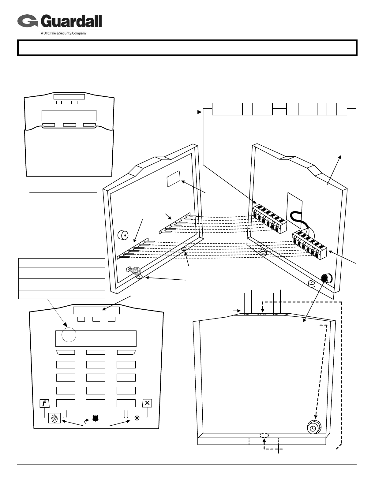
Mounting and Wiring Reference:
Keypad Terminal Block Wiring
Ratings:
LCD Keypad with Reader
Input: 12 – 13.8VDC, 110mA
Output: 12VDC, 1x10mA
Temp : -10°C to +55°C (14°F
to 131°F) @ 93%
Point
1 – 4
Standard and G-ProxII
143256
PT1
Input 1
0V
PT2 PT3 PT4
Common
Input 2
Input 3
0V
Input 4
Common
Module Bus
143256
A
+12V
B0V
Future
OUT
Flip Cover
Module Point Assignment:
7 points total.
Points 1 – 4 are hard wire
inputs.
Point 5: Fire Alert buttons
Point 6: Panic (Hold-Up)
buttons
Point 7: Auxiliary Alert
buttons
Bus Status Indicator
Online
:
;
Unit not enrolled
_
No comms on SNAPP bus
Red GreenYellow
15:25 18Sep OOO
Pin:-----
,
- #
1
45
78
X
Point 5
Red Flashing:
Protection ON
Solid: Partial
protection (STAY)
Green On Solid
with power present.
ABC
2
JKL
TUV
Z_Q
0
Point 6
Alert Labels
t
n
o
r
F
d
a
p
y
e
K
X
X
X
Circuit board pin connectors insert
into fixed terminal blocks on inside
of keypad back. This allows the
keypad to make wire connections
in the terminal blocks.
Sonalert
Tamper Spring
Apply dealer's logo label (supplied) in
the indented space at the top of the
keypad. Apply the Alert Button labels
as required.
Keypad LEDs
DEF
3
MNOGHI
6
WXYPRS
9
X
Point 7
Yellow On Solid when
points not normal or
when point in tamper.
X
X
Serial # sticker
for programming
into Module
Programming.
After placing the keypad on its back
section, make sure the keypad's securing
screws (supplied) are always I N !
Rectangular Conduit
(Trunking)
To use the keypad tamper spring as a wall tamper
break out this plastic cylinder inside the back cover.
Screw it to the wall, keeping it in the same hole as it
was attached, so the back cover fits over it.
The plastic cylinder prevents the spring from being
affected by flat objects wedged in behind the
keypad.
The additional keypad base is optional. For
installations using it there is a similar, shorter,
washer style, plastic break out.
Place it behind the plastic cylinder and screw
them down together.
Then place the holes in the base and keypad
backing over top of them.
Fit the spring insi de the plastic cylinder part
and secure the keypad front to the keypad
back. The spring compr essing should reset
the keypad tamper condition.
Output
K
e
y
p
a
d
B
a
c
k
Keypad Output
goes negative.
T
e
r
m
i
n
a
l
B
l
o
c
k
Knock outs for rectangular
conduit using additional
keypad base.
Interface with a
relay or power
Cable
supply. Common
their negatives
with keypad 0V.
Terminal
Block
Wall tamper
knock out
CSG Security Corp. / Sécurité CSG Corp. Page 2 of 4
Page 3

l
www.guardall.com | +1 877.249.9993
sales@guardall.com +1 905.206.8434 | hotline@guardall.com +1 905.206.8436 | Fax: +1 905.629.4970
Guardal
5201 Explorer Drive, Mississauga, Ont., Canada. L4W-4H1
21-3618v1.1 MONITOR ISM™ / AFx™ Suite Security 4 Zone Keypad Installation
Power and Cable Requirements:
Power Requirements
• Each 4 zone keypad’s current draw is 110 mA. Multiple modules cannot be powered direct from the module bus. A
local power supply must be used.
• Power supplies must be located very locally t o their 4 zone keypads.
• All power supply negatives must be common and connected to the ISM panel module bus negative.
• Power supply wiring has to be of a gauge large enough to provide correct voltage at the last module in a run, belonging
to that power supply. Typically 18 gauge or larger. 18 gauge power cable: Guardall P/N 947-3400.
• In a multiple floor, riser installation with a height of 10 feet (3.1 meters)/floor, using 18 gauge power cable with a lead in
of up to 100 feet (30.5 meters) from power supply to the first module, the power supply will be limited to powering
seven modules, only. This will ensure 12V at the last module of the group. The next group of 7 modules up in a vertical
formation, would then need their own power supply, located within 100 feet (30.5 meters) of that next group’s first
module.
• Seven modules will require a minimum 1 AMP power supply. A larger capacity power supply can be used, however, it
is still limited to seven modules, due to the power loss in the cable.
• A 4 zone keypad requires 12 to 13.8 volts DC to function normally. However, under extreme conditions (e.g. primary
power loss) it can still process activities marginally at 10VDC.
• The module communication cable must not carry the power supply current because of the smaller wire gau ge.
• Both wires in the power cable must be of the same gauge (e.g. 18AWG).
• However, the spare wire pair of the communication cable can be used to common the negatives of the various power
supplies with each other and the ISM module bus 0V negative, which, is required.
Cable Requirements for Module Bus Data A and B
• 24AWG, 2 twisted stranded pair, shielded, with an impedance value of 120 ohm, low capacitance: 12.5-pF/1 foot (41pF/1 meter), e.g. Belden 9842. Guardall P/N 947-3401 communication cable meets these specifications.
• The communication cable shield is grounded at the ISM main panel end (e.g. panel ground lug). “B” connected
together at each module interconnection and cut off, not connected to anything, at the last module in the group.
• The maximum module cable distance is 2000 ft (610 meters) per ISM main panel module bus 1 or 2 at the main control
unit motherboard. Module star wiring configurations cannot be used. Module connections must run on a straight trunk,
with no straight out, branch offs to another module. You must go out to the module and come back with the cable to go
to the next module.
• For ISM main panel module Bus 1 and 2 should be evenly balanced with up to 30 Suite Security keypads each to equal
the system capacity of 60.
• If more than 30 modules are required to be on a single bus, a SNAPP Expander module should be placed in series with
the SNAPP bus to split the modules into approximately two equal groups along the length of the SNAPP bus. The
SNAPP Expander module should be located near a power supply to provide power to the expander as well as the 4
zone modules.
Special Installation and Servicing 4 Zone Keypad Command Features:
Display a 4 Zone Keypad’s 5-Digit Programming Serial Number:
Prevents the need to remove the keypad housing from its base to review the Suite Security programming serial number
label on the back of the keypad’s printed circuit board.
1. Number is displayed for 4 seconds after the 7 second power up delay.
2. If unit is already powered then
• enter a valid ‘PIN’,
• select “Status”
• select “Other”
• Display will show the F/W version and unit serial number.
CSG Security Corp. / Sécurité CSG Corp. Page 3 of 4
Page 4

l
www.guardall.com | +1 877.249.9993
sales@guardall.com +1 905.206.8434 | hotline@guardall.com +1 905.206.8436 | Fax: +1 905.629.4970
Guardal
5201 Explorer Drive, Mississauga, Ont., Canada. L4W-4H1
21-3618v1.1 MONITOR ISM™ / AFx™ Suite Security 4 Zone Keypad Installation
View 4 Zone Keypad Module Bus Data Communications
3. Observe the time display on the LCD screen of the module. The character used to separate the hours from the minutes
is used to display the communication status according to the following table:
Character Meaning Possible Causes
:
;
_
Specifications:
System Architecture
RS485 communications from Module to MONITOR main panel.
Single Output
Switches to negative when activated. This is not a positive “voltage going high” output.
4 Programmable Protection Point Input Types:
h Normally Closed
h Normally open with 2.2K End of Line resistor.
Enclosure Dimensions and Mounting:
4.6” (117 mm) wide, 5.4” (137mm) high, 1.125” (29 mm) deep , (1.29” (33 mm) deep with optional trun king spacer plate)
Suitable for mounting over North American single gang electrical box or surface mount on drywall etc.
Material:
Moulded Plastic, White.
Environmental:
-10°C to 55°C (14°F to 131°F)
Humidity Range:
10% to 93%
FCC Compliance Statement:
This device complies with Part 15 of the FCC Rules. Operation is subject to the following two conditions:(1) This device may not cause harmful
interference, and (2) This device must accept any interference received, including interference that may cause undesired operation.
This equipment has been tested and found to comply with the limits for a Class B digital device, pursuant to the limits for a Class B digital device, pursuant to
part 15 of the FCC Rules. These limits are designed to provide reasonable protection against harmful interference in a residential installation. This
equipment generates, uses, and can radiate radio frequency energy and, if not installed and used in accordance with the instructions, may cause harmful
interference to radio communications. However, there is no guarantee that interference will not occur in a particular installation. If this equipment does cause
harmful interference to radio or television reception, which can be determined by turning the equipment off and on, the user is encouraged to try to correct
the interference by one or more of the following measures:
- Reorient or relocate the receiving antenna.
- Increase the separation between the equipment and the receiver.
- Connect the equipment into an outlet on a circuit different from that to which the receiver is connected.
- Consult the dealer or an experienced radio/TV technician for help.
Changes or modifications not expressly approved by GUARDALL could void the user's authority to operate this equipment.
Canadian Compliance Statement:
This Class B digital apparatus complies with Canadian ICES-003.
Online All is OK
Module does not see messages addressed to itself on
SNAPP bus, (not enrolled)
Module serial # may have been incorrectly
entered at the main control
No bus communications at all cable, connections, or module fault
CSG Security Corp. / Sécurité CSG Corp. Page 4 of 4
 Loading...