

Guardall PX 34 User Manual

PX Control Panel
User Manual
Issue A


PX Control Panel User Manual
Contents
Contents....................................................................................................................3
Introduction...............................................................................................................7
System Log........................................................................................................................................ 7
Areas & Set Groups.......................................................................................................................... 7
Circuits............................................................................................................................................... 7
User, Set group and Circuit Identification......................................................................................7
User Codes........................................................................................................................................ 8
Operator Controls and Displays..............................................................................8
System Keypads ...............................................................................................................................8
Electronic Keys................................................................................................................................ 8
Proximity Tokens.............................................................................................................................9
Keyswitch ..........................................................................................................................................9
Using the System .....................................................................................................9
Logging on ........................................................................................................................................ 9
Menu Format ................................................................................................................................... 10
Menu Layout....................................................................................................................................11
Invalid User Codes.......................................................................................................................... 11
User Access Time........................................................................................................................... 11
Engineer On Site............................................................................................................................. 11
Menu Restrictions...........................................................................................................................12
Logging Off...................................................................................................................................... 12
Help ..................................................................................................................................................12
Keypad Backlight............................................................................................................................13
Log On Messages ...........................................................................................................................13
Dual User Code Operation .............................................................................................................13
Unset .......................................................................................................................14
Unsetting Methods.......................................................................................................................... 14
Unsetting from a keypad ............................................................................................................... 14
- 3 -

PX Control Panel User Manual
Unsetting from a keyswitch ........................................................................................................... 14
Automatic Unsetting ......................................................................................................................14
Unsetting Warnings........................................................................................................................ 15
Unsetting After an Alarm................................................................................................................15
Set............................................................................................................................16
Setting from a keypad .................................................................................................................... 16
Keyswitch Setting........................................................................................................................... 16
Automatic Setting ...........................................................................................................................17
Aborting The Setting Procedure.................................................................................................... 17
Setting with Warnings.................................................................................................................... 17
Setting Faults .................................................................................................................................. 17
Failure to Set after Exit Time ......................................................................................................... 18
Reset........................................................................................................................19
Customer Reset .............................................................................................................................. 19
Engineer Reset................................................................................................................................19
Managed Reset................................................................................................................................ 19
Test..........................................................................................................................20
Sounder............................................................................................................................................20
Strobe............................................................................................................................................... 20
Audio................................................................................................................................................20
Walk Test .........................................................................................................................................20
Comms Test .................................................................................................................................... 21
Engineer Access.....................................................................................................21
PIN Change .............................................................................................................21
Adding Users..........................................................................................................22
Name ................................................................................................................................................22
Text Library....................................................................................................................................22
PIN.................................................................................................................................................... 24
Authority.......................................................................................................................................... 24
- 4 -

PX Control Panel User Manual
PIN Change......................................................................................................................................25
LogOn/Set........................................................................................................................................26
Area 1-n............................................................................................................................................ 26
Schedule 1-4....................................................................................................................................26
Logs.........................................................................................................................27
Event Log Messages ...................................................................................................................... 27
Printed Log...................................................................................................................................... 27
Log-Full............................................................................................................................................27
Log-Cct ............................................................................................................................................ 27
Log-User ..........................................................................................................................................28
Log-KP .............................................................................................................................................28
Log-Date .......................................................................................................................................... 28
Log-Alarm........................................................................................................................................ 28
Log Messages .................................................................................................................................28
Time Change...........................................................................................................31
Holiday.....................................................................................................................31
Start..................................................................................................................................................31
Stop.................................................................................................................................................. 31
Areas................................................................................................................................................ 31
Schedule .................................................................................................................32
Start Time ........................................................................................................................................ 32
Stop Time......................................................................................................................................... 32
Mon-Sun........................................................................................................................................... 32
Holiday............................................................................................................................................. 32
Bypass.....................................................................................................................33
Keypad Off ..............................................................................................................33
Chime ......................................................................................................................33
- 5 -

PX Control Panel User Manual
Print Text ......................................................................................................................................... 34
Print Holidays..................................................................................................................................34
Isolate Circuit ..................................................................................................................................34
Isolate Concentrator....................................................................................................................... 34
System Details........................................................................................................35
Keypads........................................................................................................................................... 35
Set Groups....................................................................................................................................... 35
Circuits............................................................................................................................................. 36
Users................................................................................................................................................ 38
- 6 -

PX Control Panel User Manual
Introduction
The PX Electronic Intruder Alarm System is designed to provide sec ure protection for the ins tallation.
The system is highly versatile, permitting individual s ystems to be installed and programm ed to meet
the particular security requirements of each installation.
The system comprise s a main control panel, normally located out of sight in a secure area, and at
least one keypad.
The panel has a wide range of features, which ar e program m ed by the engineer on installation, to s uit
the security requirements of the particular installation. Som e of the features may be reprogramm ed,
edited, or viewed as required by an authorised user.
System Log
The system incorporates an event log capable of recording the most recent 250 events occurring
throughout the system. The event log will record all events, f or example, user log-on tim es and user
numbers, keypad numbers, setting and unsetting times, alterations made to programmed settings,
fault conditions, etc. When the event log is full, the oldes t event will be automatically removed when
the next event occurs.
An alarm log is also provided for each configured area of the system, eac h with the capacity to record
up to 5 alarm events. The alarm log will only record the sequence of events relating to alarm or
abnormal conditions occurring in the log area. Any events in an area log will automatic ally be cleared
when the area is reset or set, providing circuits are clear.
All log events are date and time stam ped and may be viewed, or printed if a printer is fitted to the
system.
Areas & Set Groups
For protection purposes, the premises may be divided into a number of areas . Individual areas may be
grouped together into a setting group which provides the user with a convenient way of setting and
unsetting more than one area at the same time.
The installation company engineer will have configured your system for the appropriate number of
areas and groups to comply with your specific security requirements.
Where more than one area is incorporated in the system, an area(s) can be configured by the
installation engineer as a comm on area. A com m on area will autom atically set if all other areas of the
system are set and will automatically unset if any one of the other areas is unset.
Circuits
Each detector or sensor in the installation is allocated a unique circuit number. The installation
engineer will have programmed each circuit to res pond in a certain way when the circuit is activated,
when the area is set and unset. The way in which the circuit is program m ed to respond will depend on
the type of circuit and its location and purpose.
If a circuit is faulty, the alarm response may be turned off by an authorised user. This process is
referred to as bypassing.
User, Set group and Circuit Identification
Each user, set group, and circuit can be programmed with a text description of up to 14 characters. An
authorised user can change a user text descriptor.
- 7 -
PX Control Panel User Manual
User Codes
Each user of the system is identified by a unique code. This code can be a PIN code, an electronic key
or proximity token. By default all user codes are PIN c odes. An electronic k ey can only be used on a
keypad variant with an electronic key interface. A proximity token can only be used on a keypad
variant with a proximity interface.
Throughout this manual user codes are only referred to as PIN codes.
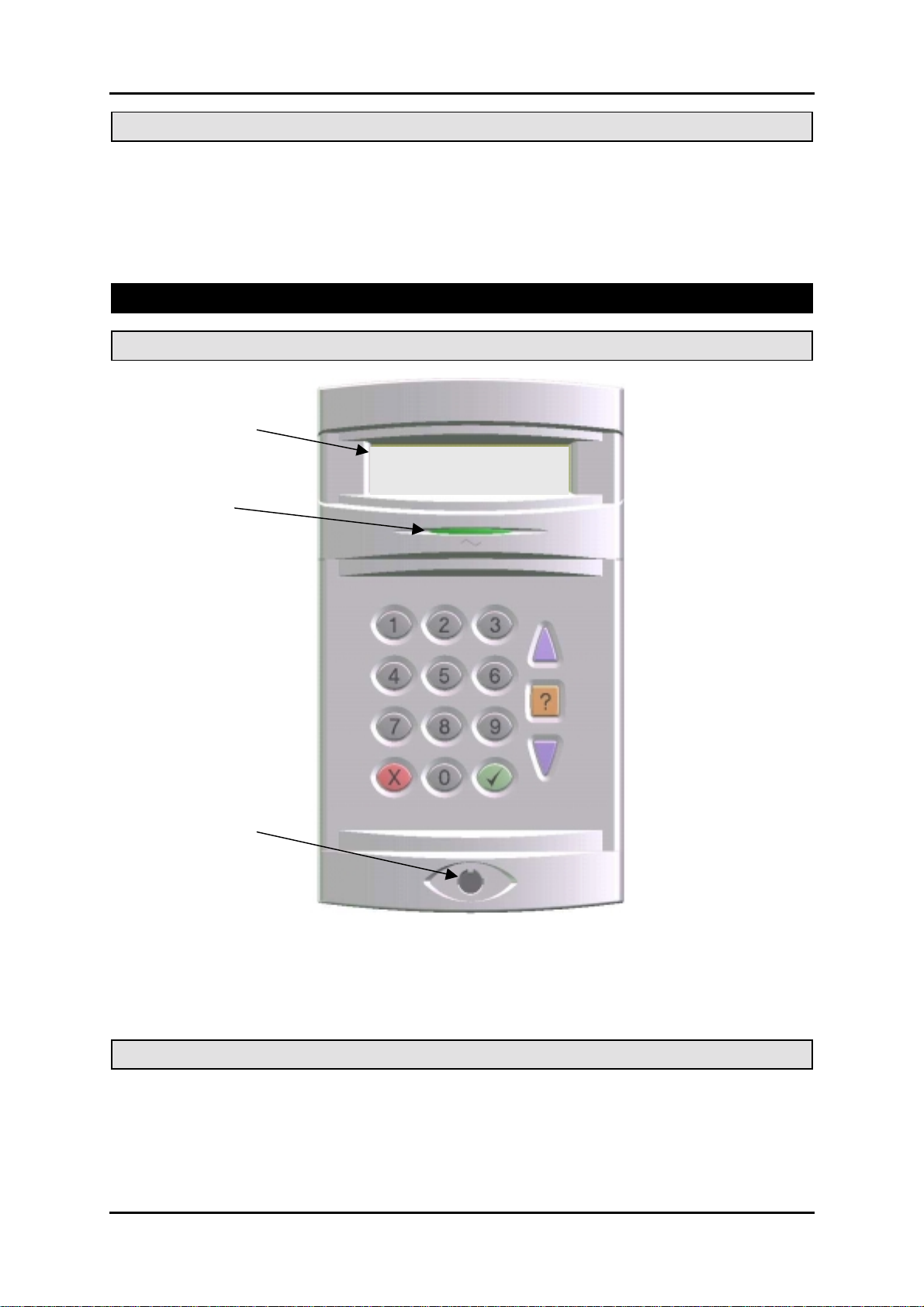
Operator Controls and Displays
System Keypads
2 x 16 character
LCD backlit display
12:00 Mon 20 Dec
Mains indicator
Optional electronic
key socket
The operator keypad unit incorporates a back lit liquid crystal display (LCD) comprising 2 lines of 16
characters, and a backlit keypad to gain access to the system and to perform all authorised user
functions. Keypads may be fitted with an electronic key socket or an internal proximity reader. The
keypad incorporates a mains power indicator. This indicator will flash if the system is operating on
standby battery power.
Electronic Keys
A user PIN code can be replaced by an electronic key. To use the facility at least one keypad in the
system must have the optional electronic key interface fitted.
All Guardall electronic keys are manufactured with a unique code and duplicate keys cannot be
obtained. Spare or replacement keys can be obtained from the installation company.
- 8 -
PX Control Panel User Manual
Proximity Tokens
A user PIN code can be replaced by a proximity token if the keypad is fitted with the optional proxim ity
reader. There are 2 types of token available; a card or key fob.
All Guardall proximity tokens are manuf actured with a unique code and duplicate tokens cannot be
obtained. Spare or replacement tokens can be obtained from the installation company.
Keyswitch
As an alternative method of setting and unsetting, a simple On/Off keyswitch may be fitted to the
system.
Using the System
When no user is logged on to a keypad, the time, date and company will normally be displayed.
12:00 Mon 27 Sep
Guardall
If programmed by the installation engineer the user can choose to show the system set areas. To
display the set areas press the or button.
Set : 14
Guardall
A user logs on to the system by either:
1. Entering a PIN code followed by ✔
2. Inserting an electronic key
3. Presenting a proximity token
The system will check that the entered us er code is valid bef ore perm itting acc ess to the system user
functions.
12:00 Mon 27 Sep
Enter-
****
The LCD keypad will normally display the time, date and company name.
In the example shown areas 1 and 4 are set.
Logging on
When a PIN code is entered the display will show an asterisk for each
digit.
- 9 -

PX Control Panel User Manual
Menu Format
User Menu
01=Unset
02=Set
03=Reset
04=Test
05=Engineer
06=PIN
07=User
10=Log-Full
11=Log-Cct
12=Log-User
13=Log-KP
14=Log-Date
15=Log-Alarm
20=Time
24=Holiday
25=Schedule
30=Bypass
31=KP Off
32=Chime
40=Print Text
42=Print Hols.
86=Isolate Cct
87=Isolate Conc
The user menu shown has all pos sible options available. The actual
options available to a user will depend on the user authority, the
system configuration and the current system status.
Only 2 options will be visible on the display but all available options
can be selected by entering the 2-digit code without viewing the actual
option number.
- 10 -
PX Control Panel User Manual
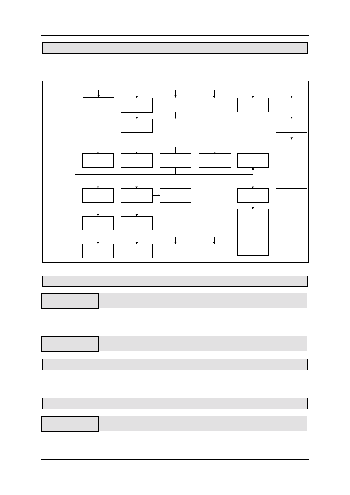
Menu Layout
The menu map shows all possible menu options and, where appropriate, sub menus.
01=Unset
02=Set
03=Reset
04=Test
05=Engineer
06=PIN
07=User
10=Log-Full
11=Log-Cct
12=Log-User
13=Log-KP
14=Log-Date
15=Log-Alarm
20=Time
24=Holiday
25=Schedule
30=Bypass
31=KP Off
32=Chime
40=Print Text
42=Print Hols.
86=Isolate Cct
87=Isolate Conc
1=Group 1
2=Group 2 ....
Circuit
Number-__
Time
00:00
Circuit
Number-__
Printing
Text
01 04
1=Group 1
2=Group 2 . . .
1=Silent Set
2=Instant Set
11
User
Number-__
20
Holiday
Number-__
30, 32
Keypad
Number-_
Printing
Holiday
02
0=System
1=Area 1 ....
?
1=Sounder
2=Audio
3=Strobe
4=Walk Test
5=Comms Test
12
Keypad
Number-__
24
Holiday 1
Start-Off
End-Off
31
4240
Circuit
Number-__
13
Filter Date
EnterDDMMYYYY
86
Concentrator
Number-_
Engineer
Guardall
05
New PIN
Enter-
.
14
1=Display
2=Print
10
15
25
Schedule
Number-__
Schedule-n
Start Time- 00:00
Stop Time- 00:00
Mon-Off
Tue-Off
Wed-Off
Thu-Off
87
Fri-Off
Sat-Off
Sun-Off
Holiday-Off
06
User
Number- _ _
1=Name
2=PIN
3=Authority
User-xx
"Descriptor"
Manager
PIN Change-On
LogOn/Set-On
Area 1-Off
Area 2-Off
. . .
Schedule 1-Off
Schedule 2-Off
Schedule 3-Off
Schedule 4-Off
07
Invalid User Codes
12:00 Mon 27 Sep
Incorrect PIN
If an incorrect user code is entered, the incorrect PIN message will be
displayed for 4 seconds or until another key is pressed.
If more than the programmed number of PIN attempts are made to enter a valid user code, the keypad
will be locked out and the display will show Out of Service for a period of 5 minutes.
12:00 Mon 27 Sep
Out Of Service
Any attempt to enter a user code during the locked out period will extend
the period by another 5 minutes
User Access Time
When a user logs on to the system a s elect ion must be made from the user m enu within tw o minutes
of log on, otherwise they will be automatically logged off.
Engineer On Site
Engineer
Out Of Service
When an engineer logs on to a keypad, all other keypads in the system
will be inoperable and the display will show Out of Service.
- 11 -

PX Control Panel User Manual
Menu Restrictions
If a menu number is entered and the option is not available, then a reason will be displayed. For
example if no area is s et and you select unset the panel will prompt with the reason the unset option is
not available.
Not Available
No Set Area
There are many reasons why an option is not available. If you think an option should be available but
the prompt is not on display then enter the menu number and the panel will display an appropriate
message. The following table shows the reasons why a menu option is not available:
Not Available Message Where Used
No Authority User tries to select an option that is not allowed with their programmed
No Set Area User selects unset when all areas that can be unset from the k eypad are
Timer Control On User attempts to log on outwith the schedule times.
No Unset Area User selects set when all areas that can be set from the keypad are
Set Area User attempts to access test when an area is set.
Test in Progress User attempts to set an area that is being tested (on another keypad).
System Not Unset User attempts to access an option that is only available when the system is
Unset Area User attempts to unset an unset area.
Key Not Used The key (button) which has been pressed is never used in the current
Printer Busy User attempts to print and the printer is in use.
Not Programmed The option selected is not programmed.
Keypad Busy User attempts to turn off a keypad that is being used.
Not Applicable User attempts, for example, to reset when there are no alarms logged.
Option in Use User selects an option, such as test, which is in being used by another
At Bypass Limit User attempts to bypass a circuit when the number of bypassed circuits is
Call Engineer User attempts to set when an engineer reset is required.
This indicates that there is no set area available to the user.
authority level.
already unset.
already set.
unset, for example the event log.
menu.
user.
at the programmed bypass limit.
Logging Off
02=Set
05=Eng
✔=Confirm LogOff
The system will display context sensitive help for m enu and programming options. W hen the main
menu is on display press the help button (?) to display information about the system.
02=Set
05=Eng
Press ✗ to log off from the main menu.
Press ✔ to confirm log off.
Help
The normal log on menu
- 12 -
 Loading...