

Page 1

DEVO-7 Page 1 of 170
Page 2

Users Manual of DEVO-7
transmitter
Partone:Generalinformation ......................................................................................... 5
1.0 FOREWORD ................................................................................................... 5
1.1 Important Statements ............................................................................... 5
1.2 Satety Needing Attention ....................................................................................... 6
1.3 Attention Before Flight ........................................................................................... 6
FEATURES ......................................................................................................................... 7
2. 1 Transmitter DEVO-7。 .......................................................................................... 7
2. 2 DEVO-RX701 ....................................................................................................... 7
3. 0 SPECIFICATION ............................................................................................................ 8
3. 1 Transmitter Specification ...................................................................................... 8
3.2 Receiver Specification ........................................................................................... 8
4.0 RADIO COVER IDENTIFICATION ...................................................................................... 9
4.1 Face Cover Indicator Diagram ............................................................................... 9
4.2 Back Cover Indicator Diagram ............................................................................. 10
4.3 Wiring Diagram .................................................................................................... 11
4.4 Function keys in panel ......................................................................................... 11
5.0 STICK ADJUSTMENT ................................................................................................... 11
5.1 Stick Length Ajustment ........................................................................................ 12
5.2 Stick Tention Adjustment ..................................................................................... 12
6.0 NECK STRAP USAGE .................................................................................................. 13
7.0 STICK MODE SWITCH ................................................................................................. 13
8.0 SWITCHES BETWEEN LEFT-HAND AND RIGHT-HAND THROTTLES ............................... 14
8.1 Right Throttle Switch To Left Throttle................................................................... 15
8.2 Left Throttle Switch To Right Throttle................................................................... 15
9.0 TRAINING FUNCTION ................................................................................................... 16
10.0 CUSTOMIZED FIXED ID ............................................................................................. 19
11.0 INSTALLATION REQUIREMENT FOR RECEIVER .............................................................. 20
12.0 INSTALLATION REQUIREMENT FOR BATTERY PAC K ....................................................... 21
12. 1 DEVO-7 Battery Charging ................................................................................ 22
PART TWO: HELICOPTER .............................................................................................. 23
SYSTEM MENU ................................................................................................................. 23
1.1 (DISPL) 1.1 Display ............................................................................................. 23
1.2 (Buzzer Setting) ................................................................................................ 24
1.3(STMOD) .......................................................................................................... 26
1.4(CALIB) ............................................................................................................ 27
1.5(ABOUT) ............................................................................................................... 28
2.0(MODEL MENU) ........................................................................................................... 29
2.1(Model select) .................................................................................................. 29
2.2 Model Name ........................................................................................................ 30
2.3(COPY) ............................................................................................................ 30
2.4 Model wireless copy ............................................................................................ 31
DEVO-7 Page 2 of 170
Page 3

2.5(RESET) ........................................................................................................... 33
2.6(TYPE) ............................................................................................................. 34
2.7(STEP) ............................................................................................................. 35
2.8 Device select ....................................................................................................... 36
2.9 Device Output ...................................................................................................... 37
2.10 Swash type ........................................................................................................ 39
2.11(AMPLI) .......................................................................................................... 39
2.12 Fixed ID ............................................................................................................. 40
3.0 FUNCTION MENU ........................................................................................................ 41
3.1 Reverse Switch .................................................................................................... 42
3.2 (Travel Adjust) ...................................................................................................... 42
3.3 (Sub Trim) ............................................................................................................ 43
3.4 Dual rate and exponential .................................................................................... 44
3.5 Throttle hold ......................................................................................................... 48
3.6Throttle Curve ....................................................................................................... 49
3.7 Mix to throttle ....................................................................................................... 51
3.8 GYRO SETTING ............................................................................................... 55
3.9 Governor .............................................................................................................. 57
3.10 SWASH MIX ...................................................................................................... 59
3.1 1Pitch Curve ......................................................................................................... 61
3.12 Program Mix ...................................................................................................... 65
3.13 (MONIT) Monitor ................................................................................................ 78
3.14 Fail safe ............................................................................................................. 79
3.15(TRAIN) .......................................................................................................... 80
3.16(TIMER) ......................................................................................................... 82
PART THREE: AIRPLANE ............................................................................................... 85
1.0 SYSTEM MENU ........................................................................................................... 85
1.1 (DISPL) ................................................................................................................ 85
1.2 Buzzer warning ................................................................................................. 86
1.3 Stick Mode ........................................................................................................... 88
1.4 Calibration ............................................................................................................ 89
1.5(ABOUT) ............................................................................................................... 90
2.0(MODEL MENU) ........................................................................................................... 91
2.1 Model Selec ......................................................................................................... 91
2.2Model Name ......................................................................................................... 92
2.3 Model Copy .......................................................................................................... 92
2.4 Model wireless copy ............................................................................................ 93
2.5 Model RESET ...................................................................................................... 95
2.6TYPE OPTION ...................................................................................................... 96
2.7 T rim system.......................................................................................................... 97
2.9 Device Output ...................................................................................................... 99
2.10(WING) ......................................................................................................... 102
1.7 Power amplifier .................................................................................................. 106
2.12(FIXID) ......................................................................................................... 107
3.0 FUNCTION MENU ...................................................................................................... 109
DEVO-7 Page 3 of 170
Page 4

3.1 Reverse Setting ................................................................................................. 109
3.2T ravel Adjust ....................................................................................................... 1 10
3.3 (Sub Trim) .......................................................................................................... 110
3.4 Dual rate and Exponiential ................................................................................. 111
3.5Throttle hold ........................................................................................................ 115
3.6Throttle curve ...................................................................................................... 116
3.7 Differential .......................................................................................................... 120
3.8 Balance .............................................................................................................. 128
3.9 Gyro sensor ....................................................................................................... 129
3.10 Governor .......................................................................................................... 132
3.1 1 Aileron to Rudder Mix ...................................................................................... 133
3.12Elevator to flap mix ........................................................................................... 136
3.13Rudder to aileron/elevator mix .......................................................................... 139
3.14(FLAPS) ....................................................................................................... 144
3.15 Aileron to flap mix ............................................................................................ 148
3.16(PRGMX) .......................................................................................................... 152
3.17(MONIT) ....................................................................................................... 161
3.18(Fail -Safe) ................................................................................................... 162
3.19(TRAIN) ........................................................................................................ 163
3.20(TIMER) ......................................................................................................... 166
PART FOUR: UPGRADE INTERFACE ....................................................................... 168
DEVO-7 Page 4 of 170
Page 5

Welcome to use the DEVO-7 transmitter
Note: Please read thoroughly the manual before using and keep it in a safe place for
the future reference.
Users Manual of DEVO-7 transmitter
Part one:General information
1.0 Foreword
DEVO-7 adopts 2.4 GHz Direct Sequence Spread Spectrum (DSSS) technology and
features automatic ID binding, automatic ID assignment, and also features fixed ID set
by you yourself. The usage of wireless copy function keeps you away from the trouble
in wire link-up. Three mode types of helicopter, airplane and glider are available to
meet your requirements for different models. The 2.8”LCD display big size letter
which offers more convenient operation. USB update on-line ensures a transmitter in
hand not to be out of date and makes it full of vigour.
1.1 Important Statements
(1) The transmitter is suitable for experienced radio controlled helicopter modelers
beyond 14 years old.
(2) Flying the model aircraft in approved ground is a must.
(3) We are not responsible for any safety caused by operation, usage or control as
soon as the transmitter is sold out.
(4) We consign our distributors to offer technical support and after sale service.
Please contact the local distributors for problem solutions caused by usage ,
operation, maintenance, etc.
DEVO-7 Page 5 of 170
Page 6

1.2 Satety Needing Attention
(1) Far away from obstacle and people
RC helicopter in flight is uncertain of flight speed and status,which potential risk exists
in. when flying, please keep your RC helicopter far away from people,high buildings,
high-tension line,etc,and avoid operating in rain,storms,thunder and lightening.
(2) Away from humidity environment
RC helicopter should be kept away from humidity and vapor because it is composed
of complicated precise electronic elements and mechanic parts.
(3) Proper operation
Please use original spare parts to upgrade,modify or maintain your equipment in
order to assure its safety. Please operate your equipment within the range of functions
permitted. It is forbidden to use out of the safety laws or regulations.
(4) Safety operation
Please operate your equipment according to your body status and flight skills.
Fatigue,listlessness and mis-operation will increase the possibilities of accidental
hazard.
(5)Away from heat sources
The inside of the transmitter is composed of many precise electronic components and
mechanical parts. Keep it far away from heat sources and sunshine to avoid
distortion,or even damage caused by high temperature.
1.3 Attention Before Flight
(1) Ensure the battery packs of both transmitter and receiver are fully charged
(saturated).
(2) Ensure both the throttle stick and the throttle trim of your transmitter stay at the
lowest positions before operation.
(3) Please strictly obey the order of turn-on and turn-off before operation. When
starting your flight, turn on your transmitter first, and connect the battery to the
helicopter later. When turning off the helicopter, disconnect the battery first, and
turn off your transmitter later. An upset in the order of connection may cause your
helicopter out of control. Please form a correct habit of turn-on and turn-off.
DEVO-7 Page 6 of 170
Page 7

(4) Ensure whether the directions and actions of the servos are correct when
executing commands of the transmitter. Using a broken servo will result in unforeseen
dangers.
2.0Features
2. 1 Transmitter DEVO-7。
1) The DEVO-7 adopts 2.4 GHz Direct Sequence Spread Spectrum (DSSS)
technology and features automatic ID binding and ID assignment. It can also be
customizedly set as fixed ID code.
2) USB online update makes you always enjoy the latest programme.
3) Adjustability of hi-frequency output power enjoys more personality and friendly
environment.
4) Wireless data transmission between two DEVO-8 helps experience the training
function.
5) Up to 15-model data can be saved.
6) DEVO-8 adjusting the gyro sensitivity makes hovering flight and fancy flight in an
easy way.
7) Ultra big size LED screen ,display letter in big size, features direct and more
convenient setting.
8) Shape design accords with human engineering and provides comfortable holding.
9) Both the length and tension of the sticks can be adjustable.
10) DEVO-7 can be freely switched among Modes 1, 2,3 ,and 4.
11) DEVO-7 is suitable for helicopter and airplane. In the helicopter mode,there are 3
flight modes , each of which can be freely set and its parameters can be
personalizedly adjusted to meet the requirement for F3C or 3D aerobatic flight.
2. 2 DEVO-RX701
1) Adopts 2.4GHz Direct Sequence Spread Spectrum (DSSS) that features fast
reaction and strong anti-jamming protection.
2) Double reveiving circuits and signal switch automatically effectively assure the
stability of receiving signal.
3) The Single Chip Microco as CPU provides super-strong analysing ability.
4) The receiver maintains the frequency and the ID memories when its changing a
DEVO-7 Page 7 of 170
Page 8

new battery pack with the transmitter powered on.
5) It can be customizedly set as fixed ID and automatic ID assignment.
3. 0 Specification
3. 1 Transmitter Specification:
Encoder: 7-channel micro computer system
Frequency: 2.4GHz DSSS
Output power ............. ≤100mW
Current drain ................ ≤230mA (100mW)
Power supply ................ 5# Battery 8X1.5V or NiMH 8X1.2V1600-2000mAh
Output pulse: 1000—2000Ms(1500 Neutral)
3.2 Receiver Specification:
Type: 2.4GHz 7 channels
Sensitivity:- 105dbm
Frequency Interval: ≥ 4M
Weight: 11.6g
Dimension: 43X28X16mm
Receiver Battery: 4.8-6V1300mAh
DEVO-7 Page 8 of 170
Page 9
4.0 Radio Cover Identification
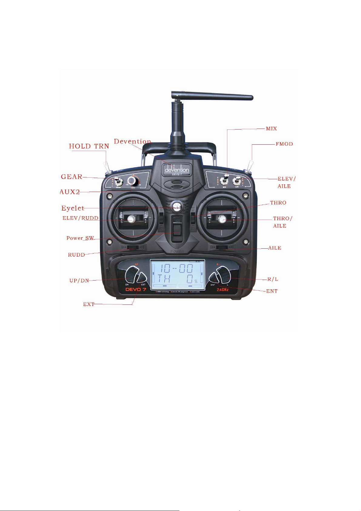
4.1 Face Cover Indicator Diagram
DEVO-7 Page 9 of 170
Page 10
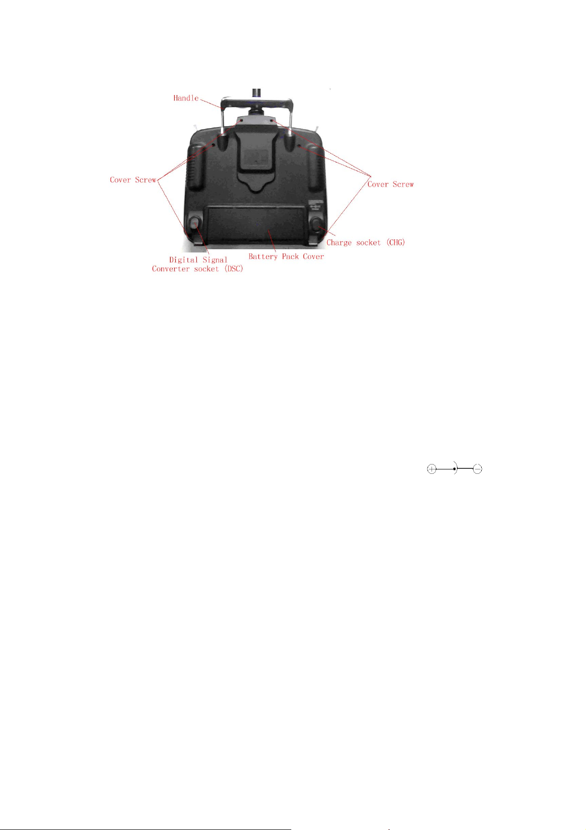
4.2 Back Cover Indicator Diagram
1. Handle
2. Cover Screw
3.Digital Signal Converter socket (DSC): used for simulator flight practice via
computer (You need a software and its dongle which are available in hobby shops),
and for training.
4. Battery Pack Cover
5. Charge socket (CHG): input DC at 12V, Current 50MAH; Polarity:
DEVO-7 Page 10 of 170
Page 11
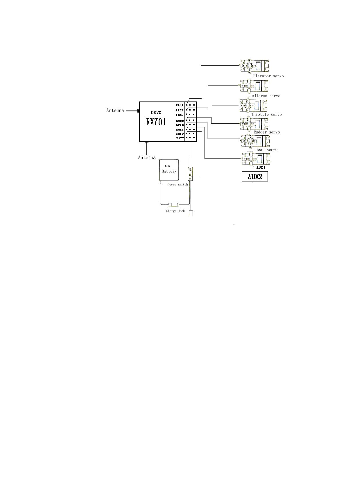
4.3 Wiring Diagram
4.4 Function keys in panel
There are 6 functional keys in the panel of DEVO-7. Below are the details:
EXT: Reset key,Press EXT to exit the main menu.
ENT: Confirmation key. Press ENT to access the system or the function mode.
·UP: Moves cursor up to the forward function item
·DN: Moves cursor down to the next Function item
·L: Moves cursor down or increases the setting value
·R : Moves cursor up or decreases the setting value
5.0 Stick Adjustment
Two parts of stick adjustment: length and tention adjustment.
DEVO-7 Page 11 of 170
Page 12
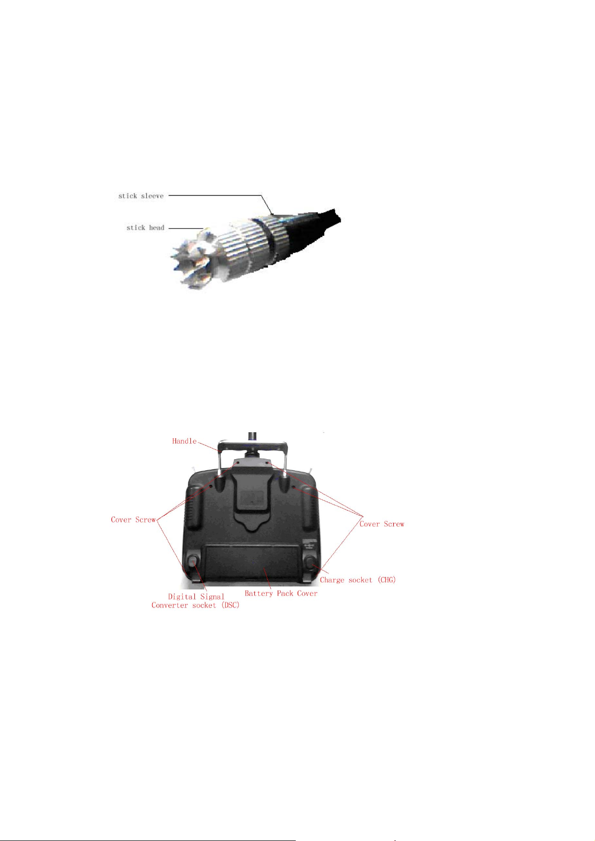
5.1 Stick Length Ajustment
Prolong the stick length: CCW rotate the stick head until the length you hope,and then
CCW tighten the stick sleeve;
Shorten the stick length: CW rotate the stick sleeve until the length you hope,and then
CW tighten the stick head.
5.2 Stick Tention Adjustment
Use the screw driver to loosen the 6 screws in the back cover, take down the base plate as
below:
Find the inside structure of the left and right throttle stick as below. Use the cross
screw driver adjust the screw F and G, clockwise will tighten the crew while
counterclockwise will loosen the screw; Cover the base plate after accomplishment.
DEVO-7 Page 12 of 170
Page 13
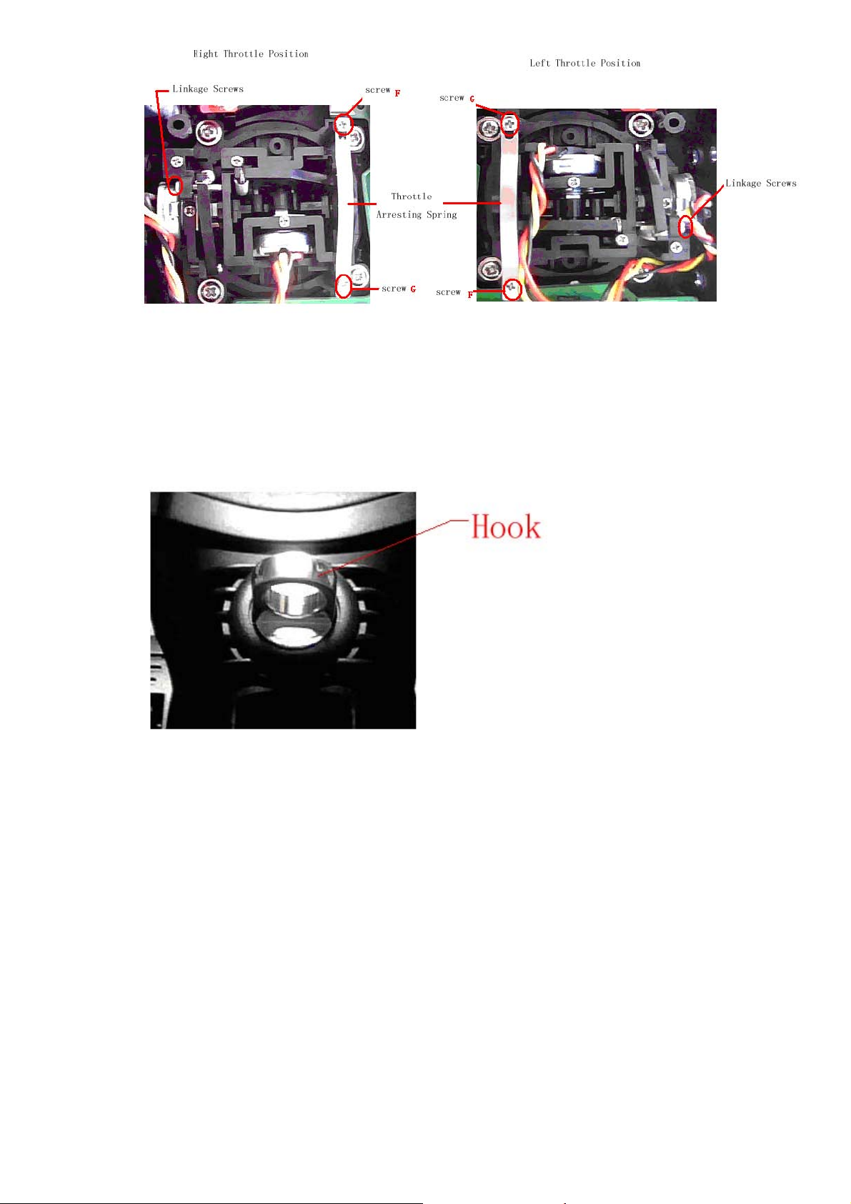
6.0 Neck Strap Usage
The hook located at the center position of the transmitter. The neck strap can be
connected to the hook. The Hook helps to get optimal balance of the transmitter.
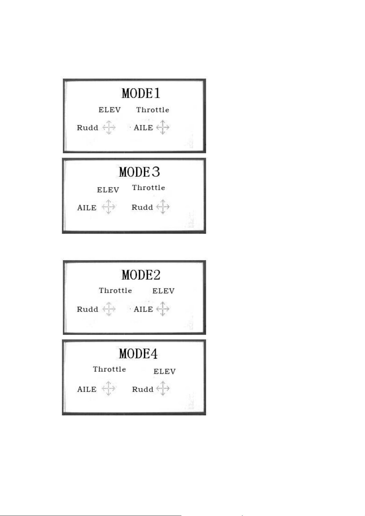
7.0 Stick Mode Switch
There are total four stick modes from MODE 1 through MODE 4. The left-hand throttle
includes MODE 1 and MODE 3, and the right-hand throttle includes MODE 2 and
MODE 4. Below is the sketch map:
DEVO-7 Page 13 of 170
Page 14
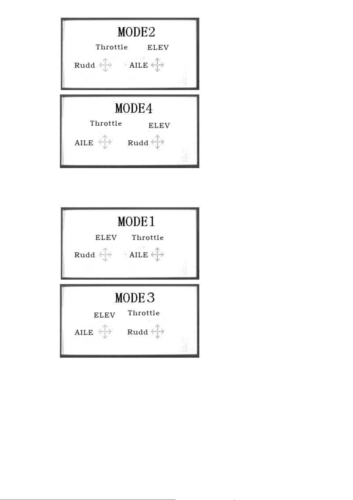
MODE 2 and MODE 4 are listed in left-hand throttle.
MODE 1 and MODE3 are listed in right-hand throttle.
8.0 Switches between left-hand and right-hand
throttles
The throttle switch between the left hand and right hand will be successful if both the
MECHANICAL switch and ELECTRONIC switch are finished, separately. Below are
DEVO-7 Page 14 of 170
Page 15
the methods for switching:
8.1 Right Throttle Switch To Left Throttle
1)MECHANICAL switch
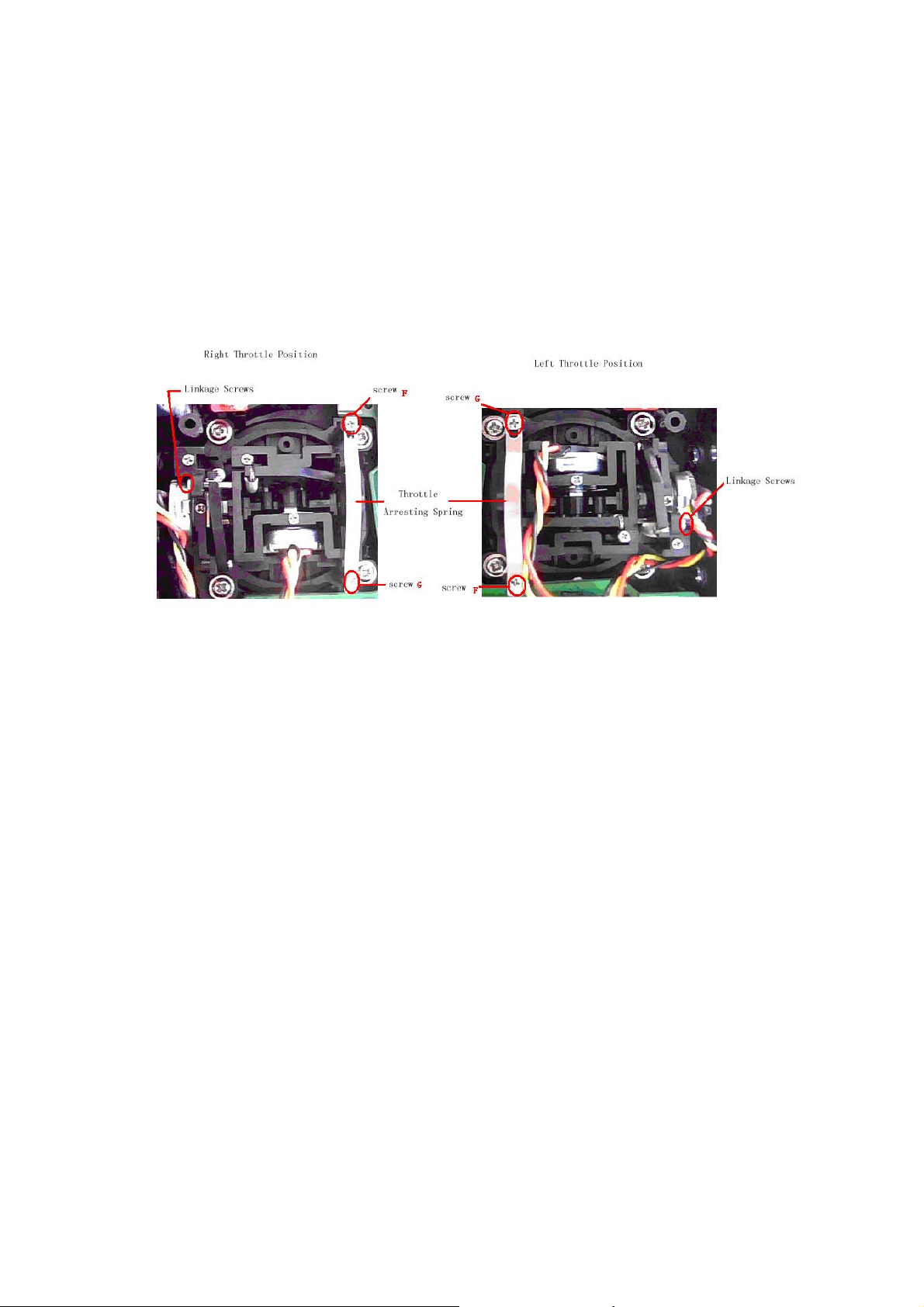
Remove the 6 fixed screws in the base plate.Below are shown the inside views of left
and right throttle sets, respectively. Use cross screwdriver to loosen and remove
Linkage Fixed Screw, Screw F, Screw G, and Throttle Control Spring in right throttle
set, respectively, and then mount them in the corresponding positions in left throttle
set. And then adjust the screw F tension according to your habit. Cover the base plate
after accomplishment
2)The ELECTRONIC switch
In the main surface touch the “ENT” Icon, it will come out the flashing “System”. Touch
the“ENT”Icon to enter System Menu; and then touch the UP or DN to enter the
flashing “
UP or DN, then come out the flashing “ MODE2” or “ MODE4”, touch “EXT” icon to
exit.
The model data will be automatically switched when touching MODE 2 or MODE 4.
The switch from right-hand throttle to left-hand throttle is finished after both the
MECHANICAL and ELECTRONIC switches changed, respectively. And the
transmitter is ready to normally work now.
STMOD” menu, press “ENT” and then select the mode you desire. Touch
8.2 Left Throttle Switch To Right Throttle
1)MECHANICAL switch
Refer to the above steps of “MECHANICAL switch”, open the base plate
DEVO-7 Page 15 of 170
Page 16
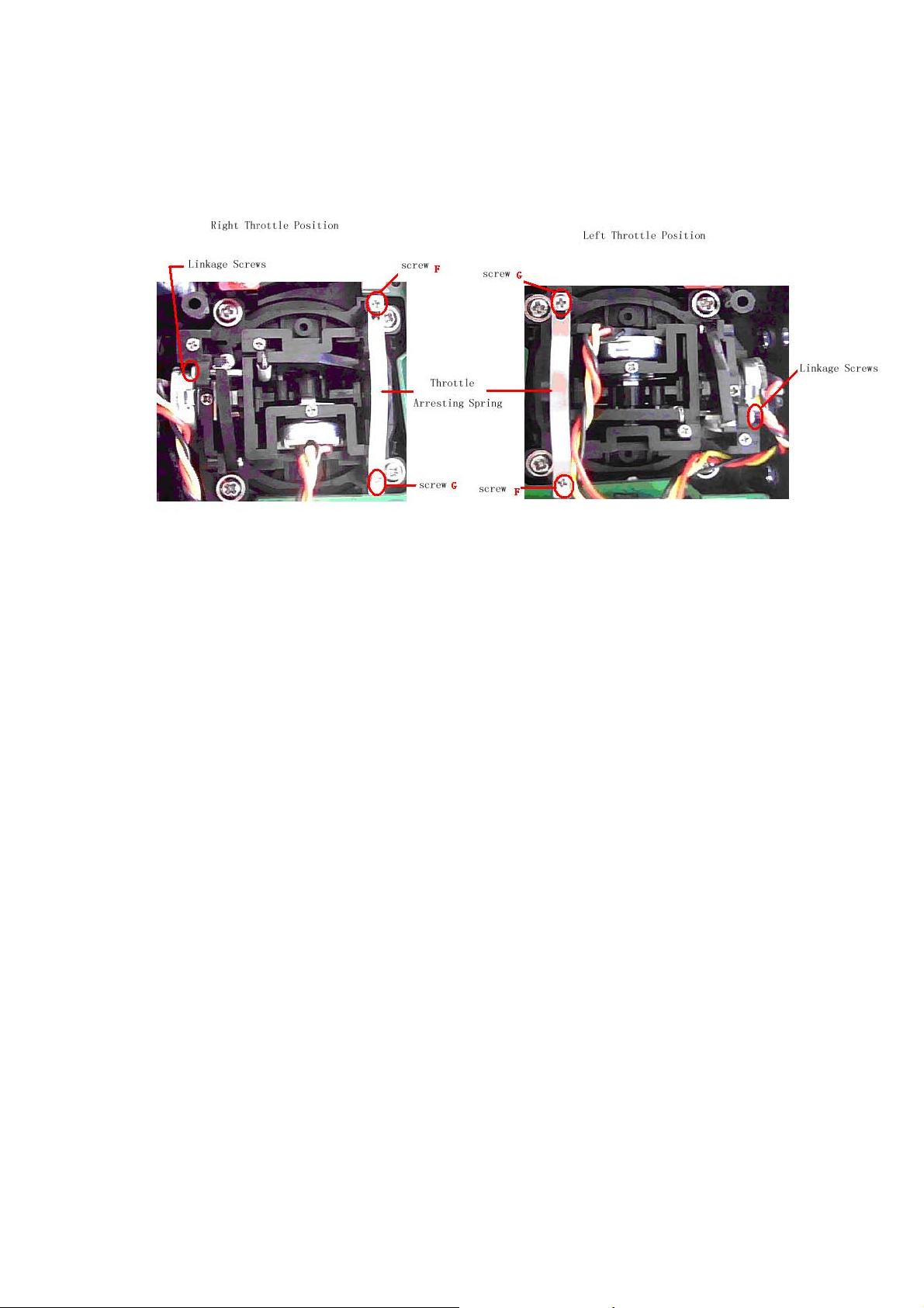
Remove the 6 fixed screws in the base plate.Below are shown the inside views of left
and right throttle sets, respectively. Use cross screwdriver to loosen and remove
Linkage Fixed Screw, Screw F, Screw G, and Throttle Control Spring in left throttle set,
respectively, and then mount them in the corresponding positions in right throttle set.
And then adjust the stick tension according to your habit.
2)The data switch
In the main surface touch the “ENT” Icon, it will come out the flashing “System”. Press
the“ENT”Icon to enter System Menu; and then press the UP or DN to enter the
flashing “
STMOD” menu, press “ENT” and then select the mode you desire. Press
UP or DN, then come out the flashing “ MODE1” or “ MODE3”, press “EXT” icon to
exit.
The switch from right-hand throttle to left-hand throttle is finished after both the
MECHANICAL and ELECTRONIC switches changed, respectively. And the
transmitter is ready to normally work now.
Note: Pay attention to the strength when removing and adjusting the screws.
Excessive strength may damage them.
9.0 Training function
Two DEVO-7 transmitters working together can execute the training function to meet
the requirements for the beginner. The setting method is shown as below:
1)Data copy
First, use the wireless copy function between two DEVO-7 to copy the main
DEVO-7 Page 16 of 170
Page 17
transmitter’s model data to the trainee’s transmitter, this promise the the model data
between two transmitters is same. Refer the copy method to the second part of
helicopter “2.4 model wireless copy” and do the following steps:
2)Linkage
Insert the signal wire from the trainer’s transmitter into the DSC socket of the trainee’s
transmitter. Turn on the transmitter and a linkage will be shown on the boot screen.
Show as below. Find out the trainee’s model data.
Linkage Display
Turn on the power of the trainer’s DEVO-7. Find out the trainee’s model data, and
then let the trainer’s DEVO-7 bind with the assigned model, fly it normally. Then turn
off the power Insert the other end of the digital signal wire into the trainer’s DEVO-7,
and then turn on its power. A linkage icon will be shown as below:
3) Setting for training function channels
Trainee is available to get full or part of flight control power to the aircraft model via
setting the training function channel in the trainer’s DEVO-7. Below is the setting
method:
Press the “ENT” in the main interface, It will come out the flashing “Function” menu;
press UP or DN to make the main interface come out the flashing “TRAIN” menu;
Press “ENT” to enter the function channel. Touch UP or DN, choose the required
channel, press R or L to change the control, INT is forbidden, ACT is granted. Press
“EXT” to exit after accomplished setting.
DEVO-7 Page 17 of 170
Page 18
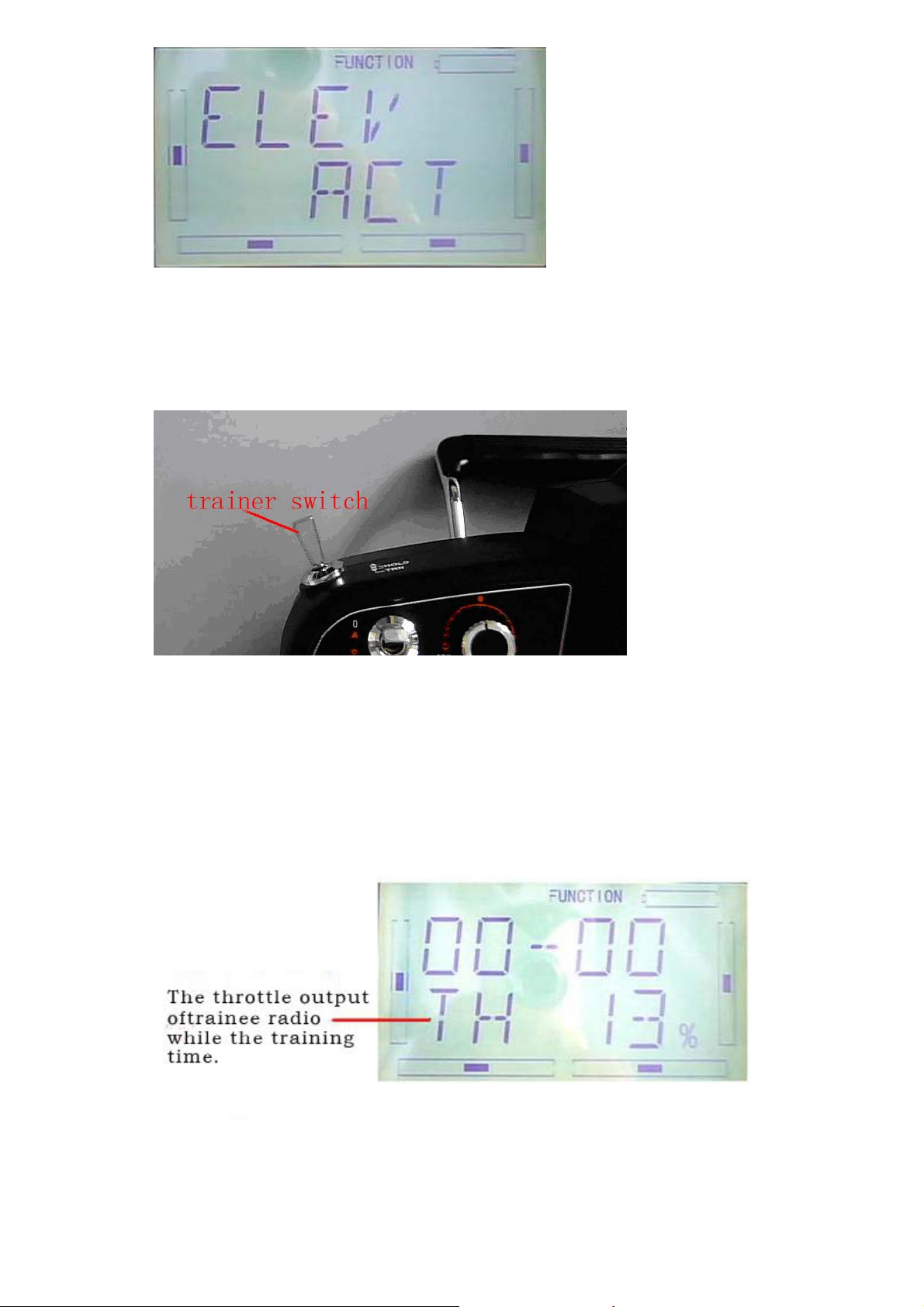
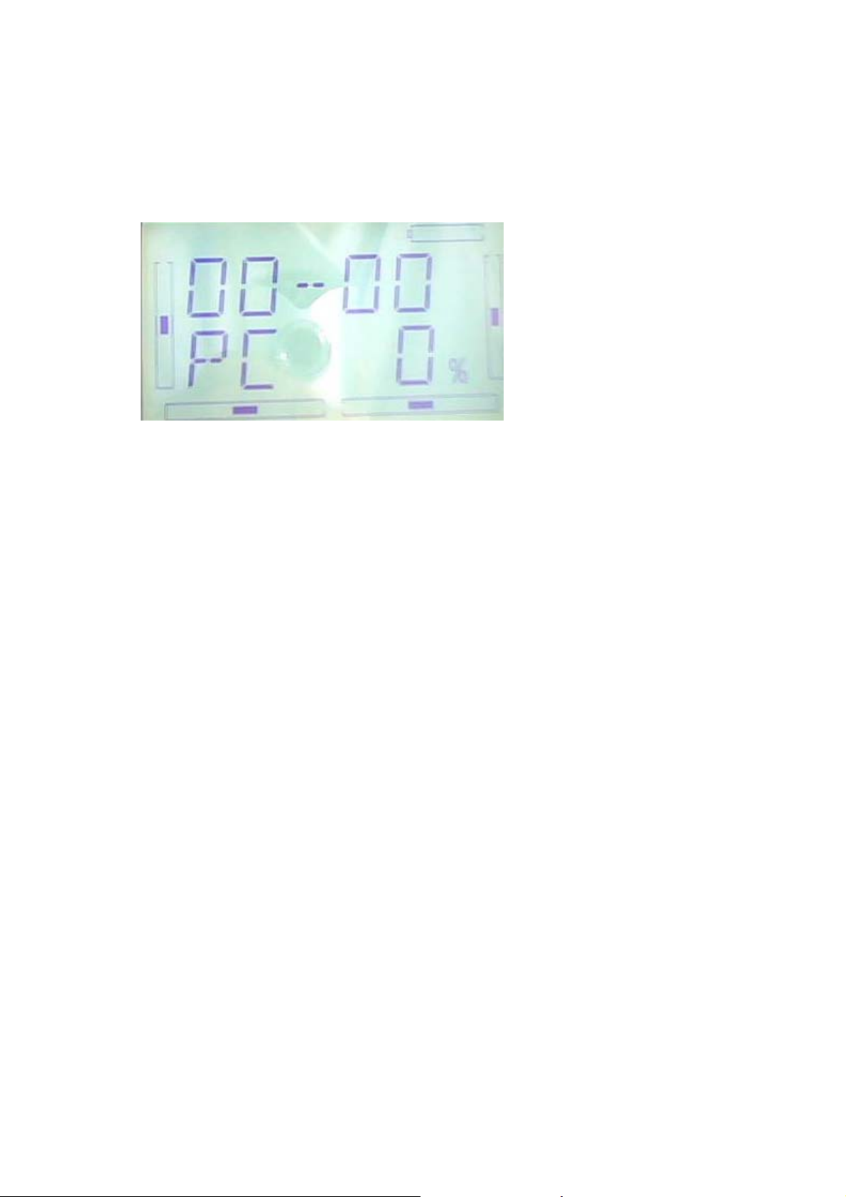
4)Usage method
The tranning switch is above the left coner,named HOLD/TRN, see below:
When flying, if the trainer push forward the TRN switch, it means the trainer has
already transfer the operate control to the trainee. At the same time, the output data
displayed on the boot screen belong to the trainee’s operate data. If the trainer push
back TRN switch, it means the trainer has recycle the operate control from the trainee
and the transmiter was operate by the trainer.
DEVO-7 Page 18 of 170
Page 19
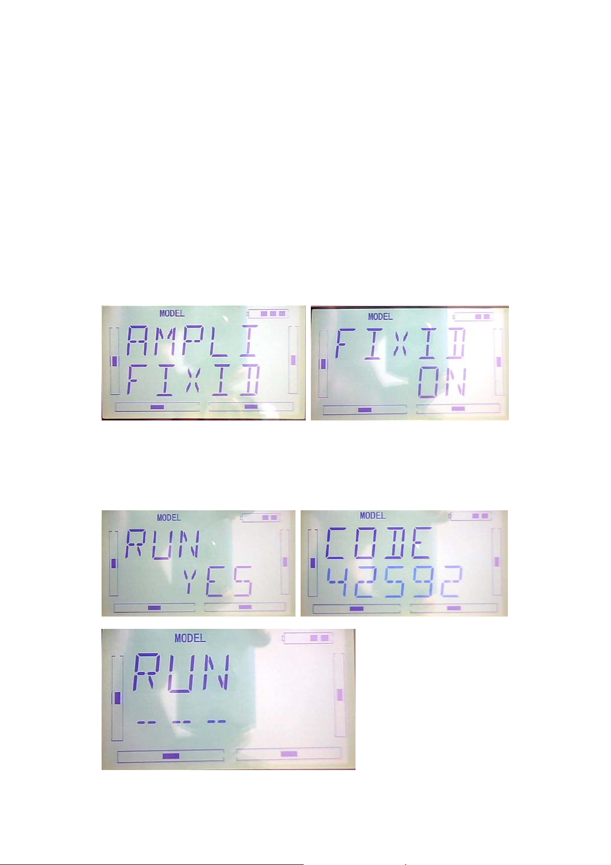
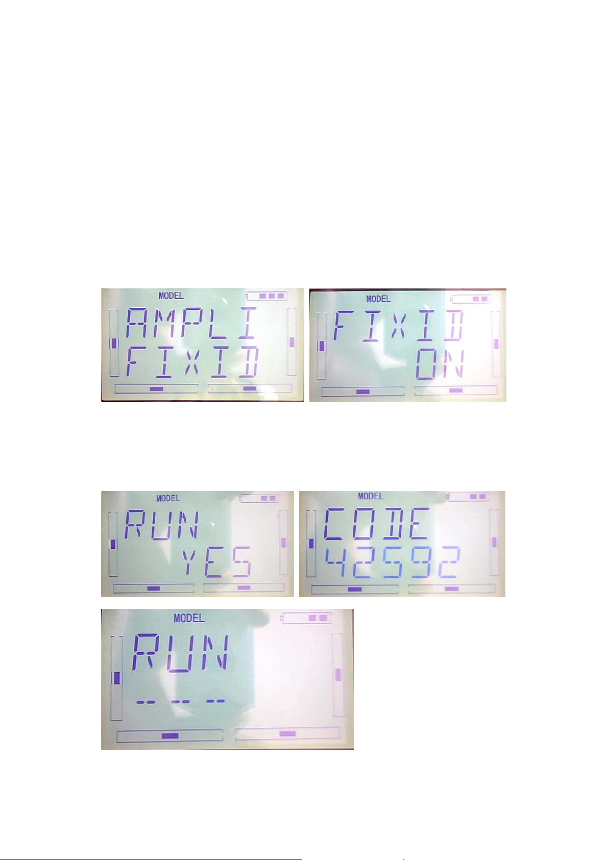
10.0 Customized fixed ID
This setting will bind the transmitter with its receiver in a unique corresponding
relationship. It will greatly speed up the time of automatic binding.
1) Setting for fixed ID
The setting for fixed ID should be under the status that automatic ID binding is
successfully finished. Below is the setting method.
Press the “ENT” on the main surface, it will come out the flashing main menu, press
UP or DN, come out the flashing “MODEL”, press “ENT” to enter Model menu;Press
UP or DN, it come out the flashing “FIXID” menu, Press “ENT” to enter the Switch
status Choose. Press R or L, choose “ON”, press DN to enter fixed ID setting.
Press ENT to change the data, press R or L to change the data; Press DN to move the
next data. After setting, press ENT, it will come out “RUN” interface. Press R or L to
change ON to YES,press ENT to make ID binding, it will automatically back to model
menu after accomplishment.
DEVO-7 Page 19 of 170
Page 20
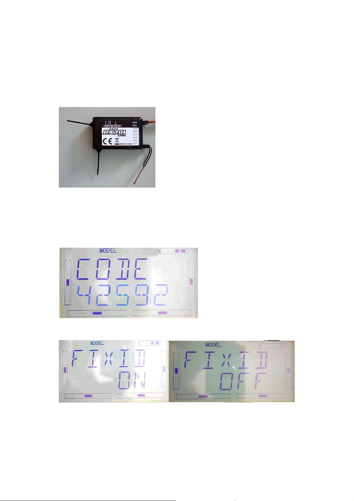
2) Fixed ID cancellation
Insert the assorted BIND PLUG into the output terminal of BATT before the receiver is
powered on, and then plug 5V DC power into other output terminal. The red light of
receiver will flash slowly. This means the fixed ID code has been cancelled. Pull out
BIND PLUG.
After the receiver’s Fixed ID cancelled, the transmitter also need to have
corresponding reset setting.
Refered to above fixed ID setting, if come to the following Image, press UP.
If come to the following image, press R or L , turn ON to OFF, press EXT to exit.
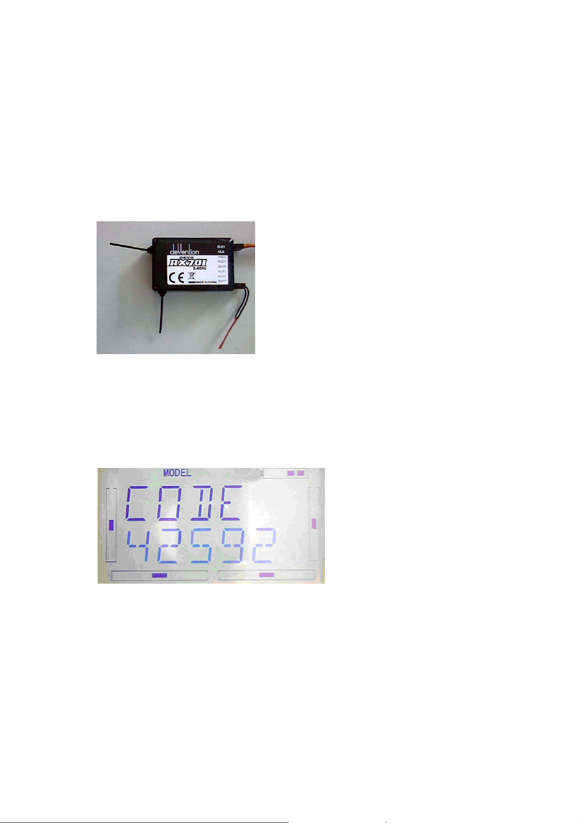
11.0 Installation requirement for receiver
1) / It is important to correctly mount your radio system in your model. Below are
DEVO-7 Page 20 of 170
Page 21

some advices on how to install your equipments.
2) Wrap the receiver with 10mm thick foam and fix it with a rubber band or magic
string on your helicopter or airplane. It helps protect the receiver.
3) It is necessary for you to use rubber grommets and copper sleeves to isolate the
vibration from the main body. The mounting screws cannot be over-tightened.
Otherwise, the rubber grommets will be distorted and decrease the vibration
absorption effect.
4) When mounting the servos, make sure the servos’ bellcranks can move freely
over their whole travel range and ensure the control linkages don't touch or
impede the movement of the servos.
5) If installing various switches, please keep them far away from the engine tuned
pipe and high vibration sources. Ensure all the switches move freely over their
whole range.
6) Don’t make the receiver antennas wrapped or parallel.
12.0 Installation requirement for Battery pack
Open the battery cover of the transmitter and take out the battery box. Then put 8 cells
AA battery or the same size full charged 8 cells NIMH battery into the battery box.
Please check again to make sure the polarities are correct.
Warning: Do not put the polarities of batteries in the opposite directions.
DEVO-7 Page 21 of 170
Page 22
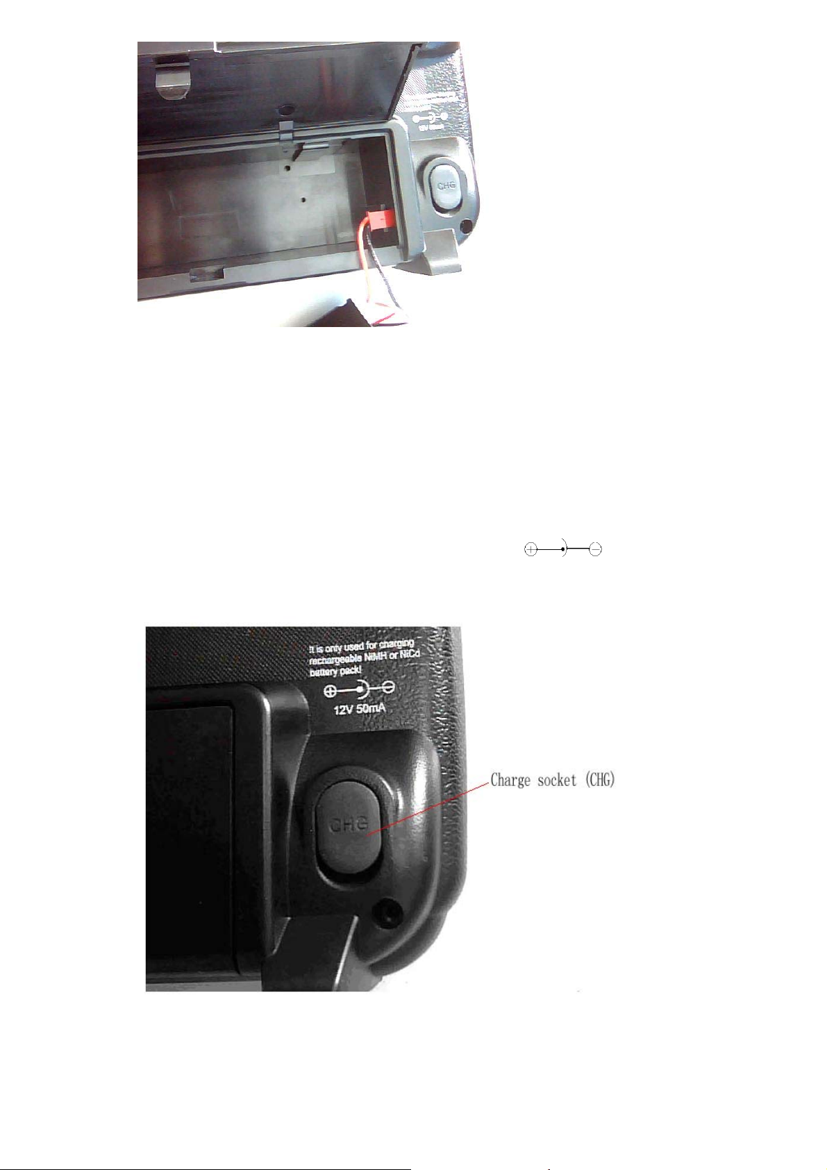
12. 1 DEVO-7 Battery Charging
Warning: the CHG socket is only used for the rechargeable NIMH batteries. If using
the batteries which is unchargeable. The CHG socket is not allowed to use.
Charge socket (CHG): input DC at 12V, 50mA; Polarity:
DEVO-7 Page 22 of 170
Page 23
Part two: Helicopter
System menu
All the functional settings, which are relative to the operation system of DEVO-7 itself,
FULLY integrated in System Menu. They include Display, Buzzer, Stick Mode,
are
Stick & Lever, and About.
Below is the boot screen of helicopter:
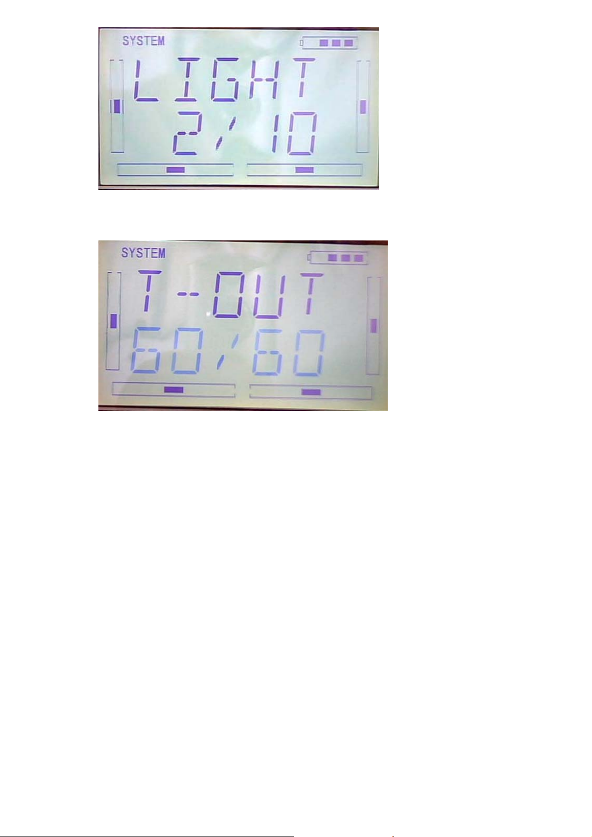
1.1 Display
1.Backlight lightness: the backlight lightness is adjustable by touching the navigation
marks. The power consumption will be increased if the backlight lightness is too bright
and the battery cruise duration will be shortened.
2.Backlight time out: it is possible to set the duration which LCD stays at highlight in
the form of “Always on” or any period from 5 to 60 seconds with an interval of 5
seconds.
3.Setting: press “ENT” key to get the flashing main memu. Press UP and DN keys
until “SYSTEM” becomes flashing, then press “ENT” key to the system menu. Press
UP or DN to get the flashing “DISPL”menu, press “ENT” to go to backlight
adjustment interface. Press R or L to adjust the backlight lightness or close it.
DEVO-7 Page 23 of 170
Page 24
Press DN to set Backlight time out, press R or L to adjust the period up to 60 seconds,
while 0 shows always ON. Press EXT key to exist after finished.
press EXT to exit
1.2 (Buzzer Setting)
Setting:
1) (STATE)Buzzer switch: press “ENT” key to get the flashing main memu. Press
UP and DN keys until “SBUZZE” becomes flashing, then press “ENT” key to the
STATE setting menu. Press R or L until the flashing characters to be ON or OFF,
ON is to set the Buzzer as active; while OFF is to set it as inhabit.
DEVO-7 Page 24 of 170
Page 25
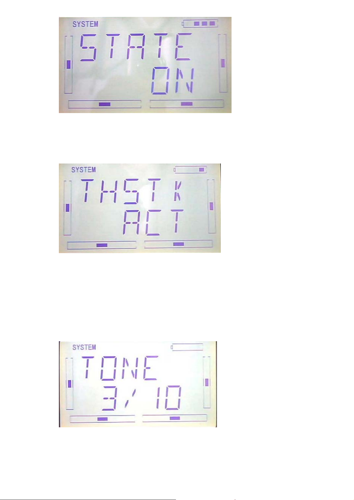
2) (THSTK)Throttle stick: under Buzzer Switch is at the status of On, if Throttle
Stick is set as “Active”, a relative musical scale will make response when moving
the throttle stick. You can judge the position of the throttle stick according to the
different musical scales. Also, it can be set as Inhibit.
After finishing the above setting, press DN key until getting THSTK setting menu.
Press R or L key to change the flashing characters to INH or ACT, ACT is to set the
Buzzer as active; while INH is to set it as inhabit.
3) (TONE) Buzzer tone: the tone is composed of 10 grades. You can choose the
favorite tone according to your interests.
After finishing the above setting, press DN key until getting TONE setting menu. Press
R or L key to change the flashing characters to numbers like 1-10.
Press EXT key to exist after finished.
DEVO-7 Page 25 of 170
Page 26
1.3(STMOD)
There are 4 stick modes including MODE1, MODE2, MODE3 and MODE4. Right
hand throttle includes MODE1 and MODE3; while left hand throttle includes MODE2
and MODE4. See Below:
MODE 2 and MODE 4 are listed in left-hand throttle.
Setting: (STMOD) Stick Mode: press “ENT” key to get the flashing main memu. Press
UP and DN keys until “STMOD” becomes flashing, then press “ENT” key to the Stick
Mode setting menu. Press R or L to select the required stick mode until it becomes
DEVO-7 Page 26 of 170
Page 27

flashing. Press ENT to confirm and press EXT to exist after finished.
1.4(CALIB)
Press “ENT” key to get the flashing main memu. Press UP and DN keys until “CALIB”
becomes flashing, then press “ENT” key to Stick Calibration setting menu. After
pressing ENT key, you will get the below interface:
Stick calibration: Clockwise or counter clockwise mechanically move the right stick
and left sticks from minimum levels to maximum levels several times, and then return
the sticks to the neutral positions, respectively.
When you get the below interface after pressed ENT key, it shows the calibration is
successful.
DEVO-7 Page 27 of 170
Page 28
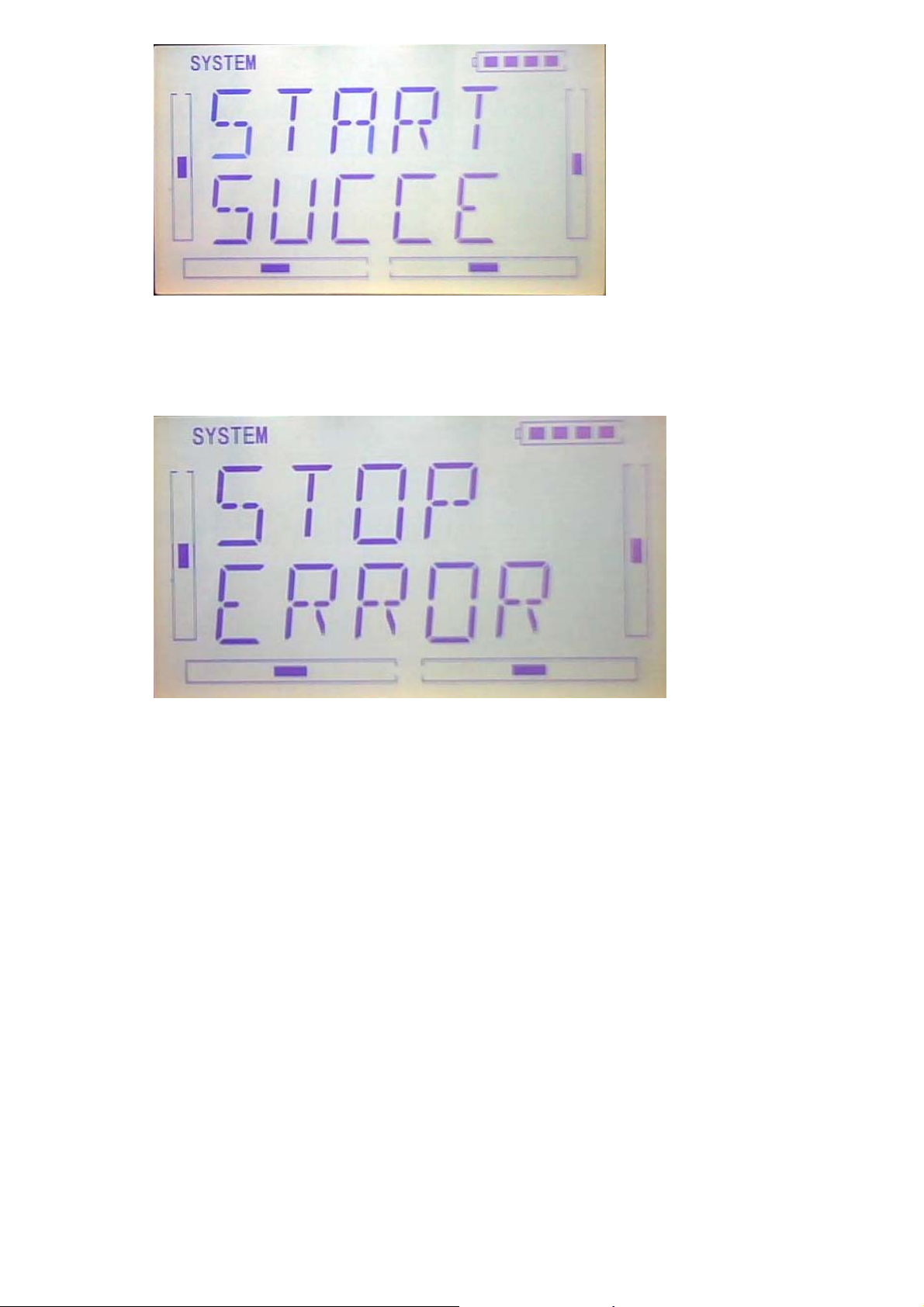
When you get the below interface after pressed ENT key, it shows the calibration is
failed, then you need to repeat the calibration.
Press EXT key to exist after finished.
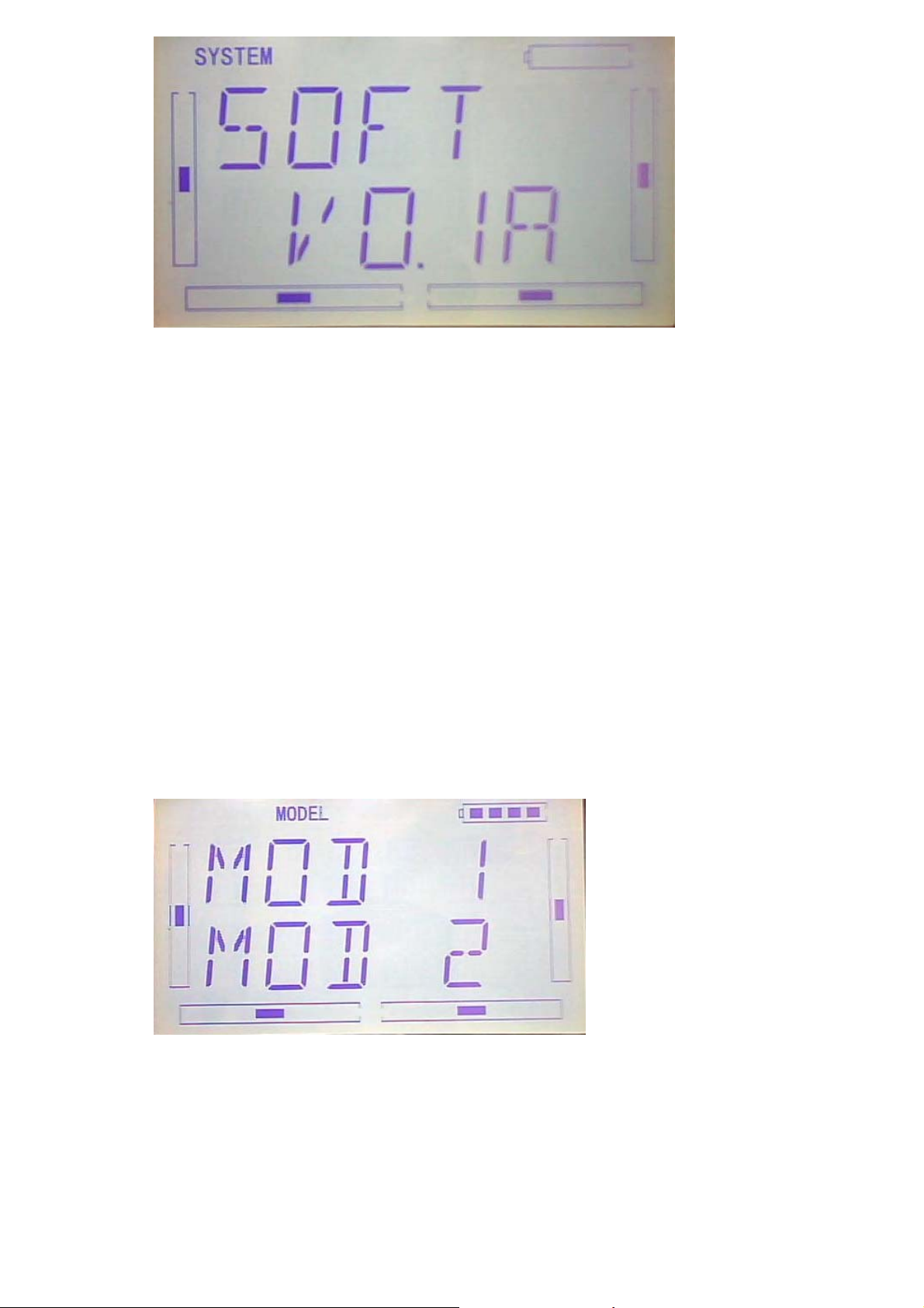
1.5(ABOUT)
press “ENT” key to get the flashing main memu. Press UP and DN keys until
“SYSTEM” becomes flashing, then press “ENT” key to system setting menu. Press
UP or DN key until “SOFT” becomes flashing; Press ENT key, you will find the version
information under the SOFT interface.
DEVO-7 Page 28 of 170
Page 29
Press EXT to exist after finished.
2.0(Model Menu)
Model Menu manages all the model data saved in DEVO-7. It includes Model Select,
Model Name, Model Copy, Model Transmit, Model Receive, Model Reset, Type Select,
Trim System, Device Select, Device Output, Swash Type, Power Amplifier and Fixed
ID.
2.1(Model select)
Press “ENT” button to enter Main Menu, press UP or DN until “MODEL” becomes
flash, then Press “ENT” button to enter Model Menu; Press UP or DN until “SELEC”
becomes flash and then press “ENT”key to get model options.
Press UP or DN key to flash the model you desired, total 15 models are optional.
Press ENT to confirm, then press EXT to exit.
DEVO-7 Page 29 of 170
Page 30

2.2 Model Name
In the menu of model name, you can make a desired name for your model for long
term storage. Its data can be directly withdrawn in next flights.
Repeat the step “2.1 Model Select” to choose the model you want to name or save.
Press “ENT” button to enter Main Menu, press UP or DN until “MODEL” becomes
flash , then Press “ENT” key to enter Model Menu; Press UP or DN until “NAME”
becomes flash and then press “ENT” button to get the Model serial NO. and original
name options.
Press UP or DN key can move the character and figure, which are needed to be
changed, Press R or L button to change the character and figure. EXT it after finish.
2.3(COPY)
Press “ENT” button to enter Main Menu, press UP or DN until “MODEL” becomes
flash , then Press “ENT” key to enter Model Menu; Press UP or DN until “copy”
becomes flash and then press “ENT” button to get the Model name options.Press R or
L can change the selected model.
DEVO-7 Page 30 of 170
Page 31

Press ENT to choose the model the enquiry interface of whether to copy will be shown.
Press R or L to select YES for reset or NO for Cancel.
Press ENT to copy and EXT to exit.
2.4 Model wireless copy
The model data between two DEVO-7 equipments can be wirelessly copied via Model
Transmit and Model Receive in Model Menu
1) Model transmission
Press “ENT” button to enter Main Menu, press UP or DN until “MODEL” becomes
flash , then Press “ENT” key to enter Model Menu; Press UP or DN until “TRANS”
becomes flash and then press “ENT” button to choose the source model.Press R or L
can change the selected model.
Press ENT to choose the model that need to transimit, the enquiry interface of
whether to transmit will be shown. Press R or L to select YES for copy or NO for
Cancel.
DEVO-7 Page 31 of 170
Page 32

Below is the picture show the interface of transimitting after press ENT.
Press EXT to exit.
2) Model receiving
Press “ENT” button to enter Main Menu, press UP or DN until “MODEL” becomes
flash , then Press “ENT” key to enter Model Menu; Press UP or DN until “RECEI”
becomes flash. The enquiry interface of whether to transmit will be shown after press
ENT. Press R or L to select YES for Receiving or NO for Cancel.
Choose YES for receiving,then press ENT “Connecting ……”interface will be shown.
DEVO-7 Page 32 of 170
Page 33

After receiving the data,the flash model name will be shown on the interface. Press R
or L can change the save position.Press ENT,there is an enquiry interface will be
shown. Press R or L to select YES for SAVE or NO for Cancel.
Data will be saved after press ENT then back to menu. Press EXT after saving.
2.5(RESET)
All the model data can be restored to factory settings via Model Reset.
Press “ENT” key to enter Main Menu, press UP or DN until “MODEL” flash , and then
Press “ENT” key to enter Model Menu; Press UP or DN button until “RESET”
becomes flash;Press “ENT” key,there are There are batch reset and single reset
selections. Press R or L to choose ALL or other models.
DEVO-7 Page 33 of 170
Page 34

Press ENT to choose the model name that need to be reset,the enquiry interface of
whether to reset will be shown. Press R or L to select YES for reset or NO for Cancel
After choosing YES,please press ENT to reset and return back to menu after reset.
Press EXT to exit.
2.6(TYPE)
This device offers two model types menu. They are helicopter and airplane
respectively.
Press “ENT” key to enter Main Menu, press UP or DN until “MODEL” flash , and then
Press “ENT” key to enter Model Menu; Press UP or DN button until “TYPE”becomes
flash;Press “ENT” key to get helicopter and Aeroplane selections. Press R or L button
until selected model becomes flash, Press ENT button to confirm, then press EXT to
exit.
DEVO-7 Page 34 of 170
Page 35
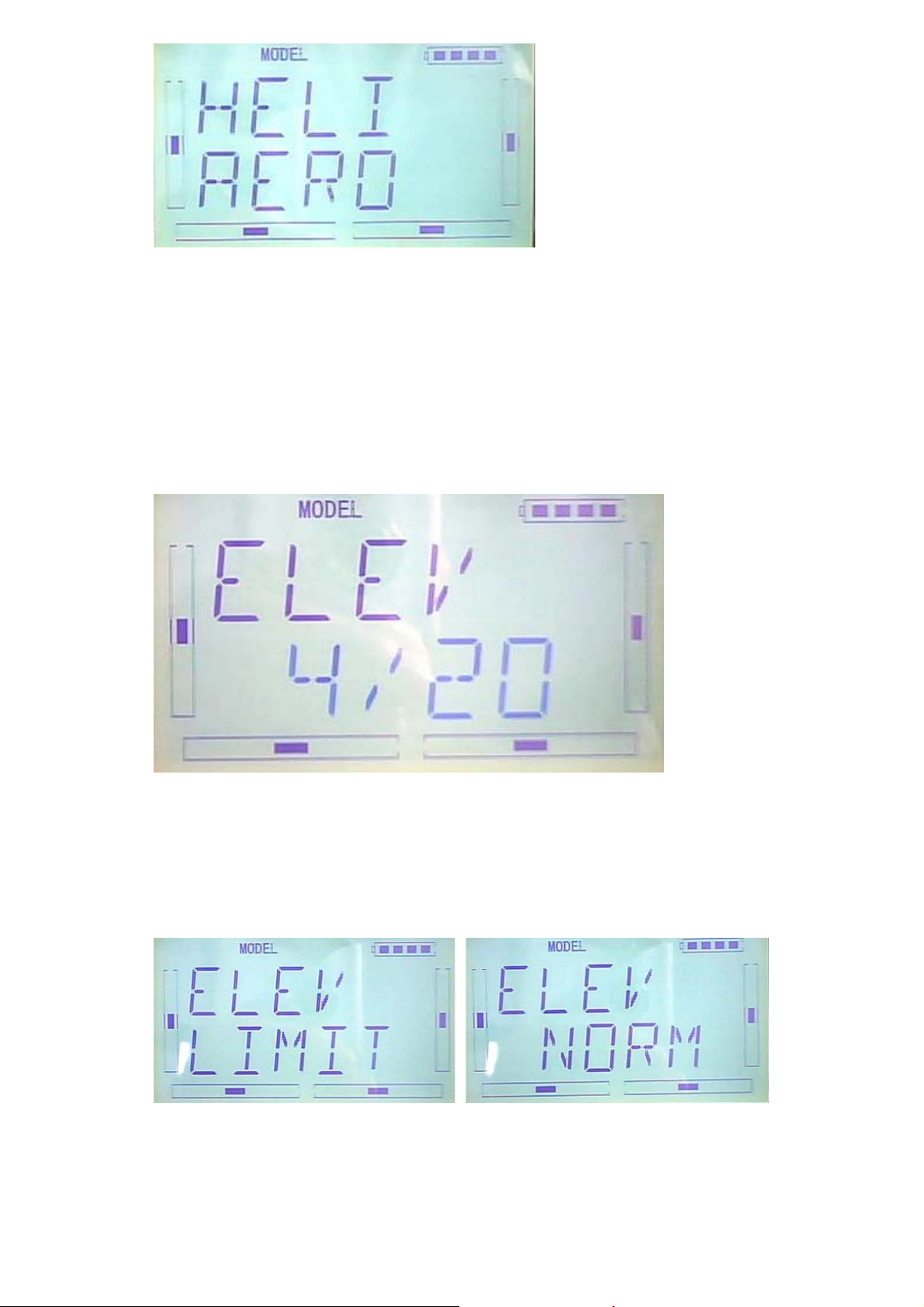
2.7(STEP)
Trim System is able to finely tune the following items, respectively: Elevator, Aileron,
Rudder, Throttle, Left Trim, and Right Trim,etc. The trim range is divided into 20
grades (factory default is set at 4). It is convenient to subtly modify the pitch by
adjusting the trim range.
For elevator, aileron, and rudder, there are two more options: Normal and Limited.
“Normal” means the trim is always working although the corresponding stick stays
anywhere. “Limited” means the trim is out of working when the corresponding stick is
at maximum position.
Press EXT to exit after setting.
DEVO-7 Page 35 of 170
Page 36

2.8 Device select
This setting can help you configure various functional switches, or adjust levers. It
includes Flight Mode Switch, Stunt Trim Select, Throttle Hold Switch.
Press “ENT” key to enter Main Menu, press UP or DN until “MODEL” flash , and then
Press “ENT” key to enter Model Menu; Press UP or DN button until“INPUT”becomes
flash. There are different options including Flight Mode Main Switch, Stunt Trim Select,
Throttle Hold Switch after press ENT.
1) Flight Mode Switch:Press R or L to choose FMD or MIX switches. factory default
setting is FMD .
2)Stunt Trim Select:There are two modes: Common and Flight Mode. In Common
mode all the trim values, which various sticks are corresponding to, put equally effects
on all the flight modes.
In Flight Mode, the trim value, which each stick is corresponding to, puts
independently effect on the corresponding stick. The factory default is Common.
Setting:After the setting 2),below interface will be shown after press DN.Press R or L
to choose Common(COMM) and Flight Mode(FMOD).
3)Throttle Hold Switch
Throttle Hold switch including Gear Switch,hold Switch,D/R switch,MIX2,MIX12,
FMD2,FMD12.Factory default setting is HOLD switch.
DEVO-7 Page 36 of 170
Page 37

Setting:After the setting 2), below interface will be shown after press DN.Press R or L
to choose corresponding switch.
Press EXT to exit after the settings.
2.9 Device Output
Device output can set up the output switches respectively. It can also activate, inhibit
or use other functions.
Setting:Press “ENT” key to enter Main Menu, press UP or DN until “MODEL” flash ,
and then Press “ENT” key to enter Model Menu; Press UP or DN button until
“OUTPU”becomes flash. The available GEAR,AUX2 options and switches will be
shown after press ENT.
1)Press R or L in OUTPU interface can change the gear switch. It includes FMD, MIX
D/R, HOLD,TRN and AUX2. The default setting is GEAR SW.
Press DN can enter the interface of Gear activate, inhibit or use other functions.
2)Press R or L can change activate, inhibit or use other functions which includes
INH,ACT and GYRO.
DEVO-7 Page 37 of 170
Page 38

3)(AUX2)
After the GEAR setting,Press DN to enter the AUX2 interface.Press R or L can
change the AUX2 switch. It includes FMD、MIX、D/R、HOLD、GEAR、TRN and AUX2.
The default setting is AUX2.
Press DN can enter the interface of AUX2 activate, inhibit or use other functions.
Press R or L can change activate, inhibit or use other functions which includes
INH,ACT,GYRO and GOV(governor).
Press EXT to exit.
DEVO-7 Page 38 of 170
Page 39

2.10 Swash type
The swash type is grouped into five options: 1 Servo Normal, 2 Servos 180°, 3 Servos
140°,3 Servos 90°, and 3 Servos 90°.
Setting: Press “ENT” key to enter Main Menu, press UP or DN until “MODEL” flash ,
and then Press “ENT” key to enter Model Menu; Press UP or DN key until“SWASH”
becomes flash. The available 1-NRM,2-180,3-120,3-140,3-90 options will flash after
press ENT.
Press EXT to exit.
2.11(AMPLI)
The transmission output power of DEVO-7 is adjustable. It is divided into six grades
from small to big. The lower the transmission output power transmits, the shorter the
radio range is, and the longer the stand-by time will be. The higher the transmission
output power, the farer the radio range, and the shorter the stand-by time. Choose the
appropriate transmission output power according to the actual situation
Setting method:
Press ENT,the flash main menu will be shown. Press UP or DN until the flash“AMPLI”
shown and then press ENT to enter the ouput power interface. Press UP or DN to
choose the appropriate output power and it will flash, press ENT to confirm.
After the setting, press EXT to exit.
DEVO-7 Page 39 of 170
Page 40
2.12 Fixed ID
This setting will bind DEVO-7 and its receiver in a unique corresponding relationship.
It will greatly speed up the time of automatic binding when DEVO-8 powered on.
1) Setting for fixed ID
The setting for fixed ID should be under the status that automatic ID binding is
successfully finished. Below is the setting method.
Press ENT,the flash main menu will be shown. Press UP or DN until the flash
“MODEL”shown and then press ENT to enter MODEL menu. Press UP or DN until
the “FIXED” flash.Press ENT to enter the status ON or OFF. Press R or L to choose
ON and press DN to enter the fixed ID setting interface.
Press ENT, the digit can be modified will be flash.Press R or L to modify the
digit.Press DN can modify the next digit. The RUN interface will be shown after press
ENT.Press R or L to change the ON to YES and press ENT to enter the binding
process. After binding, it will return to model menu automatically.
DEVO-7 Page 40 of 170
Page 41
2) Fixed ID cancellation
Insert the assorted BIND PLUG into the output terminal of BATTER before the
receiver is powered on, and then plug 5V DC power into one of the other output
terminals. The red light of receiver will flash slowly. This means the fixed ID code has
been cancelled. Pull out BIND PLUG.
DEVO-7 also needs to make relative cancellation and reversion after the fixed ID in
receiver is cleared out.
Take the fixed ID setting method as a reference .Press UP when below interface
shown.
Press R or L to change ON to OFF when below interface shown, and then press EXT
to exit.
3.0 Function Menu
Function Menu can help you make CUSTOM adjustments for the selected models.
The menu includes such items as Reverse Switch, Travel Adjust, Sub Trim, Dual Rate
DEVO-7 Page 41 of 170
Page 42

and Exponential, Throttle Hold, Throttle Curve, Mix to Throttle, Gyro Sensor, Governor,
Tail Curve, Dual Pitch, Swash Mix, Pitch Curve, Program Mix, Monitor, Fail Safe,
Trainer, and Timer.
3.1 Reverse Switch
Press ENT to enter the flashing main menu, Press UP or DN to flash “FUNCTION”,
and then press “ENT” to enter Function Menu; Press UP or DN to flash “REVSW”;
Press ENT, Channel Name and flashing normal or reverse state will be shown. Press
R or L to change the NOR or REV state. Press DN, there are normal & reverse
switches in turn for AILE, THRO, RUDD, GEAR, PITCH, GYRO and so on. The
setting are the same as above, EXT it for finish.
3.2 (Travel Adjust)
Press ENT to enter Main Menu, press UP or DN until “FUNCTION” flash, and then
press ENT to enter Function Menu; Press UP or DN button to flash “TRVAD”; Press
ENT button to enter the enactment options for channel names and flashing travel
range. Press R or L to change the enactment value of travel range; Press DN button,
there are travel range enactment options in turn for AILE, THRO, RUDD, GEAR,
PITCH, GYRO and so on. The setting are the same as above, here we take the ELEV
as example. EXT it for finish.
DEVO-7 Page 42 of 170
Page 43

3.3 (Sub Trim)
Sub Trim is used to make parallel movement of the neutral point of the servo. But we
advise you to mechanically adjust the servo bell crank if offset is far away from the
neutral point of servo. Because servo would be damaged if excessive usage of the
sub trim and beyond its range.
Setting: Press ENT to enter Main Menu, press UP or DN until “FUNCTION” flash, and
then press ENT to enter Function Menu; Press UP or DN to flash “SUBTR”; Press
ENT to enter the enactment options for channel names and flashing neutral point
value. It is possible to change the neutral point setting value through R or L button,if
the direction is reverse, change the sign “+””-” before value. Press DN button, there
are travel range enactment options in turn for AILE, THRO, RUDD, GEAR, PITCH,
GYRO and so on. The setting are the same as above, here we take the ELEV for
example.
Every channel default value is 0.0%. Adjust ranges as below:
Channel name
Adjustment range
Channel name
Adjustment
range
Elevator D62.5%-U62.5% Gear -62.5%- +62.5%
Aileron R62.5%-L62.5% Pitch L62.5%- H62.5%
Throttle L62.5%-H62.5% Gyro -62.5%- +62.5%
DEVO-7 Page 43 of 170
Page 44
Rudder R62.5%-L62.5%
EXT it for finish.
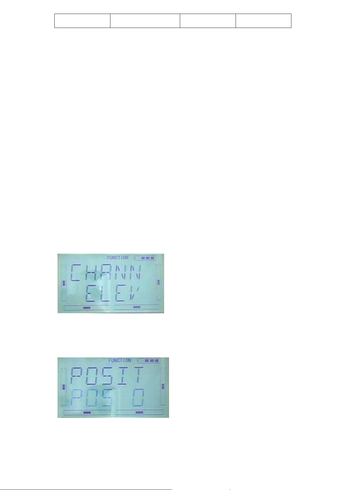
3.4 Dual rate and exponential
It is possible to use D/R switch to control over the dual rate of elevator, aileron, and
rudder,after the function of Dual Rate and Exponential is setup. The setting range is
0-125%. Under the help with exponential curve adjustment, it is not only manually but
also automatically able to set up various parameters which are suitable for yourself.
Under working with Flight Mode, it is possible to switch between the dual rate and
exponential.
1) Channel selection
Setting method: Press ENT to enter Main Menu. Press UP or DN to flash
“FUNCTION”, and then press ENT to enter Function menu; Press UP or DN until
“DREXP” blink; Press ENT to enter the options for Channel names. Press R or L,
there is a selectable list for ELEV, AILE, RUDD. Here we take the ELEV for example.
The picture as below:
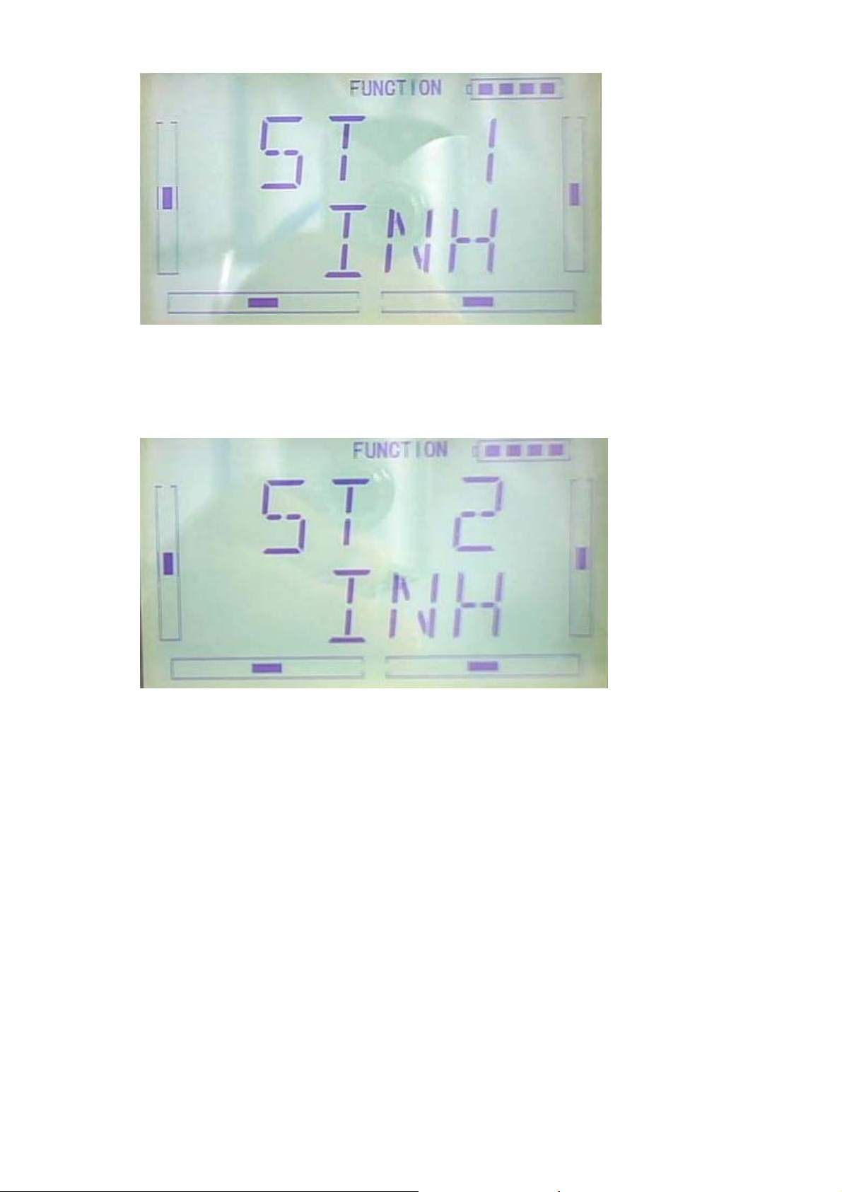
2) Position selection
Press DN to enter Switch Position setting in the above Picture, there are
POS0,POS2,POS3. Press R or L, it is possible to choose POS0,POS1,POS2,POS3.
The D/P Switch Position on transmitter
DEVO-7 Page 44 of 170
Page 45

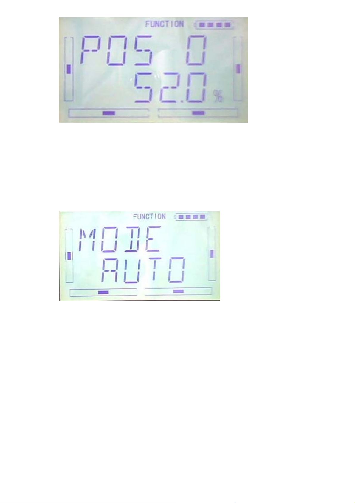
3) Dual Rate adjustment
After setup the position, press DN to enter D/R enactment interface, press R/L to
adjust D/R value.
4) Exponential adjustment
After setup the Dual Rate, Press DN to enter EXP setting interface, there are Line and
adjustable value, 2 setting options. Press R or L to choose.
DEVO-7 Page 45 of 170
Page 46

5) Automatic setting
Under working with Flight Mode, it is possible to switch between the dual rate and
exponential, which are set in above 3) Dual Rate adjustment and 4) Exponential
adjustment, respectively.
The settings for Normal Flight, Stunt Flight 1, Stunt Flight 2, Throttle Hold are available.
The Throttle hold state should be “activated” (Refer to aftermentioned”3.5” Throttle
Hold ) in “Throttle Hold”, under “Function Menu”.
After setup the Exponential adjustment, press DN to enter NORM setting interface,
Press R or L to flash “SWITC” (switch), there are opions for POS0,POS1,POS3,POS3.
Press R or L to bink the desired option.
DEVO-7 Page 46 of 170
Page 47

After setup NORM mode, Press DN to enter ST1 setting interface, the setting method
as the same as above.
After setup ST1 mode, Press DN to enter ST2 setting interface, the setting method as
above.
If the Throttle Hold is activated, it appears Throttle Hold option as below,
After setting ST2 Mode, Press DN to enter THHLD setting interface, the setting
method as above.
DEVO-7 Page 47 of 170
Page 48

Ext it to finish.
3.5 Throttle hold
If this function is activated, the switch will be executed by hold switch. The setting
value of throttle hold is ranged from -20.0 to 50.0%. The default setting is “Inhibited”.
Setting method:
Press ENT to enter the Main Menu. Press UP or DN until “FUNCTION” flash, and then
press ENT to enter Function Menu; Press UP or DN to blink “THHLD”; Press ENT to
enter the display of Throttle Hold states. Press R or L , ACT (activated) or INH
(Inhibited) is available. Factory default setting is Inhibited.
If throttle Hold is activated, “Throttle Hold Position” Menu will be shown in the
Interface.
“Throttle Hold Position” setting
Throttle Hold is activated, press DN to enter the interface as below:
Press R or L to change the Hold value. The minimum value is -20.0%; The maximum
value is +50.0%.
DEVO-7 Page 48 of 170
Page 49

The Throttle Hold Switch “HOLD” forward is to “start” , the Throttle Hold Switch
“HOLD” backward is to”close” and then Throttle Hold state is dismissed.
EXT it to finish.
3.6Throttle Curve
Press ENT to enter the flashing Main Menu. Press UP or DN until “FUNCTION” flash,
and then press ENT to enter Function Menu; Press UP or DN to blink “THCRV”; Press
ENT to enter the interface of Servo Hold State, Press R or L to choose YES or NO.
Press ENT to confim.
Flight Model options will be shown in the interface, there are NORM, ST1, ST2.
DEVO-7 Page 49 of 170
Page 50

Every flight mode curve that can be set separately.
Press R or L to choose the desired flight mode.
Press DN,the EXP on or off option will be shown. Press R or L to choose ON or OFF.
Press DN, the 7 piont options will be shown, then press R or L to choose one of 7
points, There are L、1、2、3、M、4、5、H for option. Press DN button, the output can
be set and then press R or L to set the output amount.
DEVO-7 Page 50 of 170
Page 51

Press UP to return after the setting, then choose other point to set. Press EXT to exit
after the settings finished.
3.7 Mix to throttle
This function can keep the main rotor blades running at the certain revolution caused
by the changed load when operating the aileron servo, elevator servo, and rudder
servo. It is just used for stunt flight. Generally, It is not advised to use this function.
Setting method:
Press ENT to flash Main Menu. Press UP or DN to blink”FUNCTION”, and then press
ENT to enter Function Menu; Press UP or DN until “MIXTH” flash; Press ENT to enter
Channel Option Interface; there are ELEV, AILE,RUDD available.
1.Channel setting
Press R or L to choose the channel ELEV that need to be set.
After chose the ELEV channel, press DN to enter Switch setting interface, it would be
shown as below:
2)Switch option
In above interface, Press ENT to enter Switch options and Switch state. There are
Switch options including ALLON (always on), NOR (normal mode), ST1(stunt 1),
ST2(stunt2),Gear.
ALLON(always on) option: It will be default always on if NOR (normal mode) or
DEVO-7 Page 51 of 170
Page 52

ST1(stunt 1) or ST2(stunt2) or Gear switch option is activated, but this is inhibited
automatically.
After setting ALLON (always on) option, press DN to enter NOR(normal mode) Switch
setting interface, press R or L to set the Switch activated or inhibited.
After setting NOR(normal mode) option, press DN to enter ST1 (stunt1) switch setting
interface, press R or L to set switch activated or inhibited.
After setting ST1(stunt1) option, press DN to enter ST2 (stunt2) switch setting
interface, press R or L to set switch activated or inhibited.
DEVO-7 Page 52 of 170
Page 53

After setting ST2(stunt2) option, press DN to enter GEAR switch setting interface,
press R or L to set switch activated or inhibited.
3)UP setting
After Switch option setting finished, press EXT to back Switch Option, the picture
as below:
DEVO-7 Page 53 of 170
Page 54

Press DN to enter Up setting interface and adjustable value option.
Press L button, Mix value is adjustable that means Mix value will increase when
forward push elevator rocker. The bigger of value, the bigger of Mix; Press R to get
negative value if you want reverse the direction of Throttle and Mix. Adjustable range
is ±125%.
4)Down Setting
After setting UP option, Press DN to enter DOWN setting interface.
Press L button, Mix value is adjustable that means Mix value will decrease when
backward pull elevator rocker. The bigger of value is, the bigger of Mix gains; Press R
to get negative value if you want reverse the direction of Throttle and Mix. Adjustable
range is ±125%.
5)The setting method is the same as above when “Channel” option displays “Aileron”
or “Rudder”. Press EXT to finish.
Tips:
1) Please make sure the above setting value for Mix & Throttle is good for ideal flight
and the action in various flight modes are normal.
2) The function is in spare when governor is working.
DEVO-7 Page 54 of 170
Page 55

3.8 GYRO SETTING
Press “ENT” button to enter Main Menu, press UP or DN until “FUNCTION” flash, and
then press “ENT” button to enter function Menu. Press UP or DN until
“SWHMX”becomes flash. Press ENT to get the Mode option interface. Press R or L, to
choose Manual setting or Automatic setting.
1) Manual Setting:
Press R or L to choose Manual setting, Press ENT button to enter SWITC MIX
interface, Press R or L to choose the desired Switch, MIX is the default
switch.
Press DN to enter SWITC POSITION DATA interface, the initial position is 0. Press R
or L to change value. The gyro you use owns two modes of AVCS and NOR, AVCS
will be activated when the amount is above 50.0%. The bigger the amount is, the
bigger the gyro sensor gain becomes. If the value less than 50,it’s NOR mode. The
smaller the amount is, the bigger the gyro sensor gain becomes.
DEVO-7 Page 55 of 170
Page 56
After POS 0 setup, please press DN to continue set the POS1 or POS2, which the
steps are the same as POS 0. Press EXT to finish.
2) Automatic setting
After gyro auto setup, The position range is mutative according to the flight MODE
Press R or L to choose AUTO under MODE option interface.
Press DN to enter the auto setting NORM mode, press R or L to set the amount. The
gyro you use owns two modes of AVCS and NOR, AVCS will be activated when the
amount is above 50.0%. The bigger the amount is, the bigger the gyro sensor gain
becomes. If the value less than 50, it is NOR mode. The smaller the amount is, the
bigger the gyro sensor gain becomes.
DEVO-7 Page 56 of 170
Page 57

Press DN to enter ST1 and ST2 after finish, setting steps are the same as NOR
MODE setting
Press EXT to finish.
3.9 Governor
Before setup this function, “Governor” should be set and activated in “Device output”
interface. (Refer to 2.9 Device Output)
It is possible to set Governor control rate in various flight modes separately. Please
setup the Governor for the desired retation speed. The transmitter display data is only
for percentage reference. The real rotation speed refer to Governor.
Press “ENT” key to enter Main Menu, press UP or DN until “FUNCTION” flash , and
then Press “ENT” key to enter Function Menu; Press UP or DN button until“GOVER”
becomes flash. Press ENT to enter the interface of MODE Menu and adjustable Value
options. There are “Normal mode”,”ST1”,“ST2”, “Throttle Hold” 4 options available.
NORM setting: The picture as below. Press R or L to set the value. Press R to
decrease, the minimum is -125%; Press L to increase, the maximum is +125%.
DEVO-7 Page 57 of 170
Page 58

ST1 setting: After setup the NORM option, press DN to enter ST1 setting interface.
Press R or L to set the value. Press R to decrease, the minimum is -125%; Press L to
increase, the maximum is +125%.
ST2 setting: After setup the ST1 option, press DN to enter ST2 setting interface. Press
R or L to set the value. Press R to decrease, the minimum is -125%; Press L to
increase, the maximum is +125%.
THHLD setting: Throttle Hold should be activated. After setup the ST2 option, press
DN to enter THHLD setting interface. Press R or L to set the value. Press R to
decrease, the minimum is -125%; Press L to increase, the maximum is +125%.
DEVO-7 Page 58 of 170
Page 59

Press EXT to finish.
3.10 SWASH MIX
This function is to adjust the swash mix during the flights. It will only be affected when
the swash type is 2 servos or above (refer to 2.12 swash type).
Setting Method:
Press “ENT” button to enter Main Menu, press UP or DN until “FUNCTION” flash, and
then press “ENT” button enter function Menu. Press UP or DN button until
“SWHMX”becomes flash. Press ENT button to get the setting items and value
adjustment interface. Take 3 servos 120°for example, there are 4 items including
AILE,EEV,PITCHS and EXP are adjustable.
1)Aileron Mix Adjustment
Under flashing “ SWHMX” menu, press ENT button to go to the AILE Mix Adjustment interface.
Press R button to reduce the mix and L button to increase. If the mix directions are opposite, it is
possible to reverse mix direction through R or L button to change
amount. The adjustable range is ±125%.
DEVO-7 Page 59 of 170
the plus or minus sign before
Page 60

2)Elevator mix adjustment
After AILE mix setting complete, press DN button until get ELEV mix setting interface.
If the “swash type” is 3 servos or more (refer to “2.12 Swash Type”), the setting
is the same as above.
3)Pitch Mix Adjustment
If the “swash type” is 2 servos or more (refer to “2.12 Swash Type”), the setting
is the same as above.
4)Exponential Curve
When the function is ON, the dual rate is adjustable in the “Dual rate and exponential”
under “function menu”.
Setting Method: After PITCH mix setting complete, press DN button to get into EXP
setting interface. Press R or L button to get “ON” and “OFF” options. The default
setting is “OFF”, but it is suggested to be “ON”.
DEVO-7 Page 60 of 170
Page 61

After the setting, press EXT to exit.
3.11Pitch Curve
Pitch curves are adjusted through 7 points, which of all the flight modes can be
respectively set. There are “normal flight”, stunt flight 1, stunt flight 2 and “throttle
hold” 4 flight modes.
Setting Method:
Press ENT to flash main menu. Press UP or DN key, FUNCTION will flash and then
press ENT to enter function menu. Press UP or DN, “PTCRV” will flash, press ENT
to enter the interface of servo hold , press R or L to choose YES or NO. then press
ENT to confirm.
There are “normal flight”, stunt flight 1, stunt flight 2 and “throttle hold” 4 flight modes.
The curve of each flight mode can be set respectively.
Press R or L button to choose the required flight model.
Press DN button to get the EXP ON or OFF option. Press R or L button to choose ON
or OFF.
DEVO-7 Page 61 of 170
Page 62

Press DN, the 7 point options will be shown. Press R or L to select any point from L, 1,
2, M, 4, 5 and H7. Press DN key, the output can be set and then press R or L to set
the amount.
Press UP to return, and continue to set other points. Press EXIT after the settings.
The basic examples are only for your reference. Adjustment to the real flights is a
must.
Normal
DEVO-7 Page 62 of 170
Page 63

Flight Mode: Normal
Throttle Curve Pitch Curve
Flight Mode 1
Throttle Curve Pitch Curve
Flight Mode 2
DEVO-7 Page 63 of 170
Page 64

Autorotation Landing
DEVO-7 Page 64 of 170
Page 65

3.12 Program Mix
There are 8 series of program mix, mix channels and values are adjustable.
Setting Method:
Press ENT to flash main menu. Press UP or DN, FUNCTION is flashing, press ENT to
enter function menu, then press UP or DN to flash “PRGMX”. And press ENT to
program mix setting and current status (default setting is “inhabit”) interface. Press R
or L to choose inhibited, normal or curve.
Take “program mix 1” for example, there are “normal” and “curve” setting.
A the “normal” setting of “program mix”
。
Press L button to get into the normal setting interface.
Press ENT button then expand an enquiry “All Servos Hold?” Press R or L to choose
YES or NO. If “YES” selected, all the servos will be locked in the current status, if “NO”
selected, all servos are unlocked.
DEVO-7 Page 65 of 170
Page 66

Press ENT button to get program mix 1 setting interface. There are adjustments
including main channel, slave channel, gain, offset and switch, etc.
1) Setting of main channel: See below interface, press R or L to choose the required
main channel among ELEV, AILE, THRO, RUDD, GEAR, PITCH, AUX2, OELEV,
OAILE, OPITC, ORUDD, PELEV, PAILE, PTHRO, PRUDD and FMOD。
2) Setting of slave channel: after the setting of main channel finished, press DN button.
When getting to below interface, choose the required slave channel among ELEV,
AILE, THRO, RUDD, GEAR, PITCH and GYRO.
3) Setting of Gain: Take Elevator as main channel as an example. Press DN button
DEVO-7 Page 66 of 170
Page 67

after slave channel is set, then get to gain setting interface.
3.1) Mix amount setting when elevator stick moved upward:
Press R to decrease the mix amount and press L to increase. It is possible to reverse
mix direction by pressing R or L button to change the plus or minus sign before
amount. The adjustable range is ±125%.
3.2) Mix amount setting when elevator stick moved downward:
Press DN button after the above setting is finished. Press R to decrease the mix
amount and L to increase. It is possible to reverse mix direction by pressing R or L
button to change the plus or minus sign before amount. The adjustable range is
±125%.
3.3) Offset Setting: it can be started from any position in “slave channel” through
related switch.
After mix amount setting when elevator stick moved downward finished, press DN
button to get to Gain Setting Interface. Press R to decrease the mix amount and L to
increase. It is possible to reverse mix direction through changing the plus or minus
sign before amount. The adjustable range is ±100%.
DEVO-7 Page 67 of 170
Page 68

3) Switch: After setting Gain, press DN button to get to switch setting interface and
shown current status. Press ENT button to the switch setting including all on, normal
mode switch, ST 1 switch, ST 2 switch, D/R switch, HOLD switch and GEAR switch.
ALLON ( always on): if normal mode switch, ST 1 switch, ST 2 switch, D/R switch,
HOLD switch and GEAR switch are all active, then this switch is inhibited. The default
setting is ALL ON.
DEVO-7 Page 68 of 170
Page 69

After setting ALLON (always on), press DN button to get to NOR (normal flight) switch
setting interface. Press R or L to set the switch inhibited or active.
After setting NOR ( normal flight ), press DN button to get to ST 1 ( Stunt flight 1 )
switch setting interface. Press R or L to set the switch inhibited or active.
After setting ST 1 ( Stunt flight 1 ), press DN button to get to ST 2 ( Stunt flight 2 )
switch setting interface. Press R or L to set the switch inhibited or active.
DEVO-7 Page 69 of 170
Page 70

After setting ST 2 ( Stunt flight 2 ), press DN button to get to D/R switch setting
interface. Press R or L to set the switch inhibited or active.
After setting D/R, press DN button to get to HOLD switch setting interface. Press R or
L to set the switch inhibited or active.
DEVO-7 Page 70 of 170
Page 71

After setting HOLD, press DN button to get to GEAR switch setting interface. Press R
or L to set the switch inhibited or active.
After finished, press EXT to exit.
:
B “ Curve” setting of “ Program Mix”
Press ENT to flash main menu. Press UP or DN, FUNCTION is flashing, press ENT to
enter function menu, then press UP or DN to flash “PRGMX”. and press ENT to
program mix setting and current status (default setting is “inhabit”) interface. Press R
or L to choose inhibited, normal or curve.
Take “program mix 1” for axample, and choose “curve” setting.
DEVO-7 Page 71 of 170
Page 72

Press ENT button then expand an enquiry “All Servos Hold?”. Press R or L to
choose YES or NO. If “YES” selected, all the servos will be locked in the current
status, if “ NO” selected, all servos are unlocked. Press ENT button to get program
mix 1 setting interface.
1) Setting of main channel: See below interface, press R or L to choose the required
main channel among ELEV, AILE, THRO, RUDD, GEAR, PITCH, AUX2, OELEV,
OAILE, OPITC, ORUDD, PELEV, PAILE, PTHRO, PRUDD and FMOD。
2) Setting of slave channel: after the setting of main channel finished, press DN button.
When getting to below interface, choose the required slave channel among ELEV,
AILE, THRO, RUDD, GEAR, PITCH and GYRO.
DEVO-7 Page 72 of 170
Page 73

3) Exponential curve: after setting the slave channel, press DN button to get to the
EXP setting. When getting to below interface, press R or L to choose from EXP “ ON
“ or “ OFF”. The pitch curve will be smoothly changed if choosing On. Otherwise
choosing Off.
4) Point setting: Press DN, the 7 piont options will be shown. Press R or L to select
any point from L, 1, 2, M, 4, 5 and H7.
DEVO-7 Page 73 of 170
Page 74

Press DN to get to setting status.
5) State setting: See below interface, press R or L to choose from “ Inhibited” or
“ Active”. If no changes, choose Inhibited (the default setting is Inhibited); choose
Active for changing the amount.
Press DN button to get to output setting.
6) output setting: See below interface, press R to decrease the output amount to
minimum -100%; press L to increase the output amount to maximum +100%.
It is possible to reverse mix direction by pressing R or L button to change the plus
or minus sign before amount.
7) Switch: after finishing output setting, press DN button then get to Switch setting
interface and the current switch status will be shown.
Press ENT button to get the switch setting including ALLON, normal mode switch, ST
1 switch, ST 2 switch, D/R switch, HOLD switch and GEAR switch.
DEVO-7 Page 74 of 170
Page 75

ALLON ( always on): if normal mode switch, ST 1 switch, ST 2 switch, D/R switch,
HOLD switch and GEAR switch are all active, then this switch is inhibited. The default
setting is ALL ON.
After setting ALLON (always on), press DN button to get to NOR (normal flight) switch
setting interface. Press R or L to set the switch inhibited or active.
After setting NOR (normal flight), press DN button to get to ST 1 (stunt flight 1) switch
setting interface. Press R or L to set the switch inhibited or active.
DEVO-7 Page 75 of 170
Page 76
After setting ST 1 (stunt flight 1), press DN button to get to ST 2 (stunt flight 2) switch
setting interface. Press R or L to set the switch inhibited or active.
After setting ST 2 (stunt flight 2), press DN button to get to D/R switch setting interface.
Press R or L to set the switch inhibited or active.
DEVO-7 Page 76 of 170
Page 77

After setting D/R switch, press DN button to get to HOLD setting interface. Press R or
L to set the switch inhibited or active.
After setting HOLD switch, press DN button to get to GEAR setting interface. Press R
or L to set the switch inhibited or active.
DEVO-7 Page 77 of 170
Page 78
After finished, press EXT to exist.
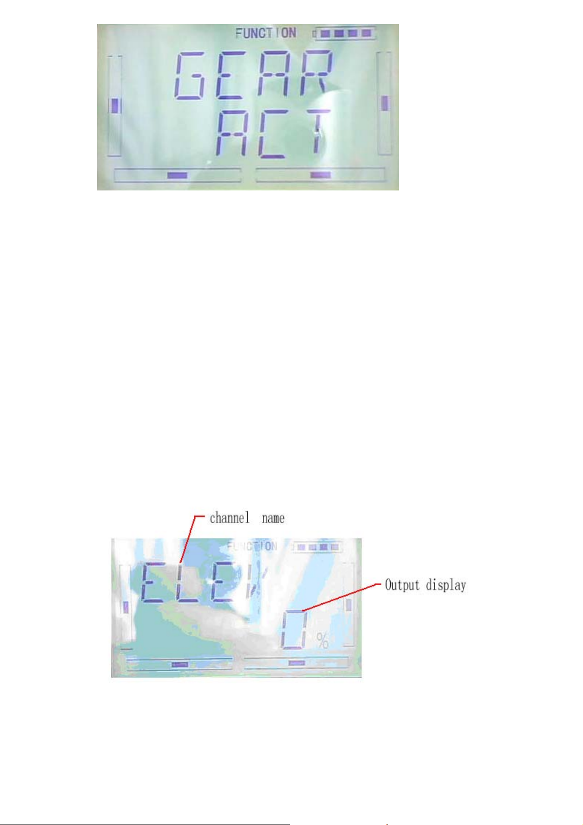
3.13 (MONIT) Monitor
This function can display the current statuses and positions of all the channels’ outputs, and
check the current working status of each channel.
Press “ENT” button to enter flashing Main Menu, press UP or DN until “FUNCTION”
flash, and then press “ENT” button enter function Menu. Press UP or DN button until
“MONIT”becomes flash. Press ENT button to get the name of ELEV channel and
output display. Press R or L to check other channels’ name and output.
channel name
Output display
After finished, press EXT to exist.
DEVO-7 Page 78 of 170
Page 79

3.14 Fail safe
There are two possibilities for use if the transmitter signal is under abnormal
condition,the first one is lock the last action date received; the second one is to
execute the pre-set date which is pre-set. The default setting is Servo Hold
setting method:
Press ENT to enter flash main menu. Press UP or DN until FUNCTION flash,repress
ENT flash to enter function menu; press UP or DN until SAFE flash ;press ENT to FAIL
SATE setting interface. There are ELEV,AILE,THRO,RUDD,GEAR,PITCH,GYRO 7
channel setting. Take the item Elevator as an example to explain.
On above interface,press R or L to selet keep or fail safe. If selecting keeping,locking
the last dated received; If selecting fail safe, to execute the pre-set date which is
pre-set. The default setting is Servo Hold
Press R to SAFE,press DN to enter fail safe date interface
DEVO-7 Page 79 of 170
Page 80

Press R or L(if servo keep neutrally,etc 0%),to decrease or increase the position
amount which centers on the neutral point of servo.The settable range is 125%,and
0% is the servo’s neutral position.
Setting finishing DN to set other channel.
The setting methods for other channels are the same as above
Press EXT to exit after finished
Note: checking whether all the actions when fail safe happened correct is a must after
the setting is finished.It is dangerous to use full throttle,especially after fail safe taken
place
3.15(TRAIN)
Two DEVO-7 transmitters working together can execute the training function to meet
the requirements for the beginner. The setting method is shown as below:
1)Data copy
Using the wireless copy function of the two DEVO-7 transmitter, the model saved in
the trainer’s transmitter can be transmitted to the trainee’s to ensure the model
parameters are exactly same.
2)Linkage
Insert the signal wire from the trainer’s transmitter into the DSC socket of the trainee’s
transmitter. Turn on the transmitter and a linkage icon will be shown on the boot
screen. Showed as following interface.Find out the trainee’s model data.
linkage icon
Turn on the power of the trainer’s transmitter,find out the trainee’s date and let the
trainer’s devo 7 fly the aircraft normally. After testing flying normal, insert one end of
the signal wire into DSC socket at the rear face o the trainer’s.
DEVO-7 Page 80 of 170
Page 81

3) Setting fro training function channels
By setting trainning function channels, trainee can obtain all or parts of operation
rights of designated channel function.The following is setting method.
Press ENT to show flash main menu. Press UP or DN to flash FUNCTION, repress
ENT to enter function menu; Press UP or DN to untill flash TRAIN menu, press ENT to
channel selection. Press UP or DN,select controlled channel,press R or L to change
channel controlled right, INT for forbidden; ACT for granting. Press EXT to exit after
finishing setting.
4)usage method
The training switch should be worked with HOLD/TRN,as following
DEVO-7 Page 81 of 170
Page 82

During flying, if trainer pull TRN front and keep it,that means trainer already hand over
the controlled right to trainee. At the same time, the output date of open interface
should be the operated data of trainee. If trainer move away TRN, that means trainer
will get back the operated right from trainee and operate the model.
3.16(TIMER)
There are two timers which can be set shopwatch and countdown,respectively.Each
timer can be operated by switch.
DEVO-7 Page 82 of 170
Page 83

Press”ENT” to flash main menu. Press”UP” or”DN” to be showed flash”FUNCTION”
then press”ENT” to enter function menu; Press UP or DN,make interface showed
flash”TIMER” menu, press”ENT” to enter type selection. There are stopwatch and
countdown. Press R or L to select.
Stopwatch setting, the following interface for stopwatch,press EXT to exit
The max range of stopwatch is from 0 to 59 min 59 sec
A:Countdown setting: press R or L on press the above interface to select counterdown
setting as following;
DEVO-7 Page 83 of 170
Page 84

Press DN on above interface to enter countdown
Press R or L to set countdown. The countdown rang of is from00:05-59:55.
C:usage
Press UP on “ on” interface AN to start on the first time,repress UP to stop; press
DN,timer is the orginal 0
stopwatch interface
coundown interface
DEVO-7 Page 84 of 170
Page 85

Part three: Airplane
1.0(system)
1.0 System menu
The related functions of Devo 7 are integrated to SYSTEM MENU, including DISPLAY,
BUZZE, STICK MODE, STICK CALIBRATION and ABOUT.
The boot screen of airplane is shown as below:
1.1 (DISPL)
1 ) Backlight brightness: the backlight brightness can be adjusted. The power
DEVO-7 Page 85 of 170
Page 86

consumption will be increased if the backlight lightness is too bright and the battery
cruise duration will be shortened.
2)Backlight time out: it is possible to set the duration which LCD stays at highlight in
the form of Always on and duration from 5 to 60 seconds with an interval of 5 seconds.
SETUP: press ENT key in main interface, it appears twinkling main menu. Press UP
or DN to get twinkling SYSTEM, and then press ENT to enter system menu, press UP
or DN to get twinkling DISPL menu.
Press ENT key to enter brightness adjustment, you can adjust the brightness or turn
off the backlight by press R or L.
Press DN in above interface to enter backlignt time out setup, press R or L you can
adjust the backlight duration, 60 seconds is longest time, 0 means always on.
Press EXT to exit after finished.
1.2 Buzzer warning
1) Buzzer switch: Press ENT key in main interface, it will shows twinkling main
menu. Press UP or DN to get twinkling “SBUZZE”, and press ENT to enter STATE
menu. Press R or L to make twinkling figure turn into ON or OFF. On means
active, OFF means inhibitive.
DEVO-7 Page 86 of 170
Page 87

2)Throttle stick: under Buzzer Switch is at the status of On, if Throttle Stick is set as
“Active”, a relative musical scale will make response when moving the throttle stick.
You can judge the position of the throttle stick according to the different musical scales.
Also, it can be set as Inhibit.
After finish above setup, press DN to enter THSTK setup interface. Then press R or L
to set twinkling figure is INH or ACT. ACT is active, INH is inhibitive.
3)Buzzer tone: the tone is composed of 10 grades. You can choose the favorite tone
according to your interests and make a listening test.
After above setup, Press DN to get TONE setup interface, then Press R or L to
confirm the tone grade you want.
DEVO-7 Page 87 of 170
Page 88

Press EXT to exit after finished.
1.3 Stick Mode
There are four stick modes from MODE 1 to MODE 4. Right-hand throttle includes
MODE 1 and MODE 3, Left-hand throttle include MODE 2 and MODE 4.
Please see below picture.
MODE 2 and MODE 4 are listed in left-hand throttle.
Stick Mode setup: Press ENT key in main interface and it will appears twinkling main
DEVO-7 Page 88 of 170
Page 89

menu. Press UP or DN to get twinkling “STMOD”, and then press ENT to enter stick
mode selection. Press R or L to choose stick model you desired, and then Press ENT
to confirm.
Press EXT to exit after finished.
1.4 Calibration
Press “ENT” key in main interface then it will appears twinkling main menu. Press UP
or DN to get twinkling “CALIB”, and then press ENT to enter calibration menu.you can
start calibration after press ENT key.
Press ENT to start stick calibration, it appears below interface.
Stick Calibration: Clockwise or counter clockwise mechanically move the right stick
and left sticks from their minimum levels to their maximum levels several times, and
then return the sticks to the neutral positions, respectively.
If shows below interface after press EXT, it means calibration is finished.
DEVO-7 Page 89 of 170
Page 90
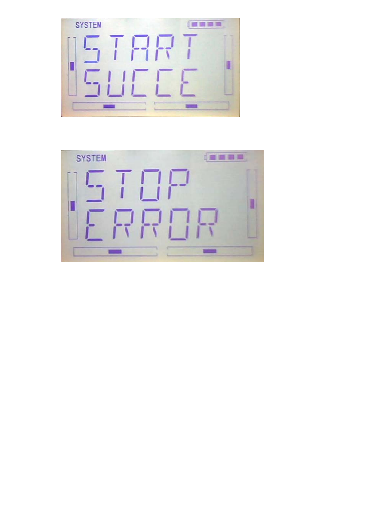
If shows below interface after press EXT, it means calibration failed and you should
calibrate again
Press EXT to exit after finish.
1.5(ABOUT)
Press the key “ENT” in main Interface then it will show a twinkling Menu. Press “UP”
or “DN” to get a twinklyng “SYSTEM”, And then press “ENT to enter system menu.
Press “UP” or “DN” to get twinklyng “
interface, you can check the versions of hardware and software.
DEVO-7 Page 90 of 170
ABOUT”. And then press “ENT” to get SOFT
Page 91

Press EXT to exit after finish.
2.0(Model Menu)
Model Menu manages all the model data saved in DEVO-7. It includes Model Select,
Model Name, Model Copy, Model Transmit, Model Receive, Model Reset, Type Select,
Trim System, Stick Position, Warning, Device Select, Device Output, Wing Type and
Fixed ID.
2.1 Model Selec
Press ENT to flash main menu in main interface, press UP or DN, MODEL will flash, and
then press ENT to enter model menu; Press UP or DN to flash SELEC, Press ENT to enter
into Mode Selec
Press UP or DN to flash MODE, there are 15setting memories for option.
Press ENT to confirm, and press EXT after finish.
DEVO-7 Page 91 of 170
Page 92

2.2Model Name
In the MODEL NAME menu, you can give a name to your heli as your expect and
save it for next time’s flightt.
Please repeat the step”2.1 model selec”, choose mode number you want to rename
and to save.
Press ENT to flash main menu in main interface, press UP or DN to flash MODEL,
then press ENT to enter model menu; press UP or DN to flash NAME, press ENT to
show model number and old name
Press UP or DN to move the character and figure need to change, press R or L to
change the character and figure. Press EXT after finish.
2.3 Model Copy
Press ENT to flash main menu in main interface, and press UP or DN to flash MODEL, then
press ENT to enter model menu, press UP or DN to flash COPY; press ENT to show source
model, and press R or L to choose model source again.
Press ENT to show model you want to change, and press ENT, the inquiring interface
will be shown. Press R or L to choose ON or YES, and then press YES to copy, press
NO to give up.
DEVO-7 Page 92 of 170
Page 93

Press ENT to back to menu after copy and then press EXT
2.4 Model wireless copy
The model data between two DEVO7 can be copied and shared through model
transfer and model receiving in model menu.
1)Model transfer
Press ENT to flash main menu in main interface, press UP or DN to flash MODEL,
then press ENT to enter model menu, press UP or DN to flash TRANS, press ENT,
model name ready for transfer will be shown. Press R or L to choose model
After choose the model to transfer, please press ENT to enter inquiring interface.
Press R or L to choose ON or YES, press YES to copy and press NO to give up.
DEVO-7 Page 93 of 170
Page 94

Press ENT, it is transferring, refer to image as below:
Press EXT after finish
2) (RECEI) model recei
Press ENT to flash main menu in main interface, and press UP or DN to flash MODEL,
then press ENT to enter model menu; Press UP or DN to flash RECEI, and press ENT
to enter the inquiring interface. Press R or L to choose ON or YES, and choose YES to
receiver, choose NO to give up.
Choose YES to receive, and press ENT to show model connecting interface…
DEVO-7 Page 94 of 170
Page 95

The model name will flash after model date trasfer, and press R or L to change the
save place for model data. Press ENT to enter inquiring interface. Press R or L to
choose ON or YES. Choose YES to save and choose No to give up.
Press YES to save data and press ENT to back to menu.
Press EXT to after finish
2.5 Model RESET
Press MODE RESET to recover all data to factory setting
Press ENT to flash main menu in main interface. Press UP or DN to flash MODEL,
and then press ENT to enter model menu. Press UP or DN to flash RESET, press
ENT to enter item for option. There are WHOLE RESET or UNIQUE RESET for option.
Press R or L to choose item need to reset.
DEVO-7 Page 95 of 170
Page 96

Press ENT to enter the inquiring interface. Press R or L to choose ON or YES, press
YES to continue and press NO to give up.
Press ENT to confirm and back to menu. Press EXT after finish.
2.6TYPE OPTION
There are two type for option: helicpter and airplane.
Press ENT to flash main menu in main interface. And press UP or DN to flash MODEL,
and press ENT to enter into model menu. Press UP or DN to flash TYPE, and press
ENT. There are helicopter and airplane for option, press R or L to flash the item be
chosen.
Press EXT after finish
DEVO-7 Page 96 of 170
Page 97

2.7 Trim system
Trim System is able to finely tune the following six items, respectively: Elevator,
Aileron, Rudder, Throttle, Left Trim, and Right Trim. The trim range is divided into 20
grades (factory default is set at 4). It is convenient to subtly modify the pitch by
adjusting the trim range.,settings are belows:
Press ENT in the main interface,main menu blinking,,press UP or DN to sppear
“MODEL”then press ENT to enter model menu, press UP or DN, “STEP”
blinking,Press ENT to appear selectable options, there are elevator, aileron, and
rudder, step range,Press R or L to change the step range,the maximun is 20
there are elevator, aileron, and rudder, Normal and Limited. “Normal” means the
trim is always working although the corresponding stick stays anywhere. “Limited”
means the trim is out of working when the corresponding stick is at maximum position.
Press R or L to select Normal and Limited,once finished, press EXT to exit.
2.8 Device select
This setting can help you configure various functional switches, or adjust levers. It
DEVO-7 Page 97 of 170
Page 98

includes Flight Mode Main Switch, Stunt Trim Select, Throttle Hold Switch, Hovering
Pitch, and Hovering Throttle.
1)Press ENT in the main interface, main menu blinking, press UP or DN to appear
blinking MODEM”,then press ENT to enter the model menu, press UP or DN to
appear blinking “INPUT”,press ENT to appear selectable options,there are Flight
Mode Main Switch option, Throttle Hold Switch option, Hovering Throttle options
2) Flight Mode Main Switch
Press R or L to select INH,FMD or MIX switch, The factory default setting is FMOD
SW.
3) Stunt Trim Select
There are two modes: Common and Flight Mode. In Common mode all the trim values,
which various sticks are corresponding to, put equally effects on all the flight modes.
In Flight Mode, the trim value, which each stick is corresponding to, puts
independently effect on the corresponding stick. The factory default is Common.
Settings: once finished the step2 , press DN to appear below interface,press R or L to
select COMM or FMOD
DEVO-7 Page 98 of 170
Page 99

4)Throttle Hold Switch
There are GEAR switch,HOLD switch,D/R switch, MIX2、MIX12、FMD2、FMD12,
The factory default is HOLD switch
5) Settings: once finished the step2 , press DN to appear below interface,press R or L
to select switch
Setting method: once finished the step3 , press DN to appear below interface,press R
or L to select MIX or FMD switch,once finished the setting, press ENT to exit,
2.9 Device Output
Device output can set up the output switches and select the usage of levers,
respectively. It can also activate, inhibit or use other functions.
Setting method:
Press ENT in the main interface, main menu will be blinking, press UP or DN to
DEVO-7 Page 99 of 170
Page 100

appear blinking “MODEL”, then press “ENT” to enter model menu, press UP or DN to
appear blinking “OUTPUT”;press ENT to appear setting items and selectable switch,,
There are three adjustable items. They are Gear, AUX2 and AUX3, respectively.
1)Under the above interface,press R or L to change to select GEAR switch or button
option,ther are FMOD SW, MIX SW, D/R, HOLD , GERA SWTRN and AUX and
so on. The default setting is GEAR SW.
Press DN to enter GEAR ACT ,INHIBIT and other functions options,
Press R or L to change select ACT ,INHIBIT and other functions options,there are
INH、ACT、GOV。
2)FLAP
After set the GEAR , press DN to enter the FLAP setting, see belows, press R or L to
change select FLAP SW or BUTTON option,there are FMD MIX D/R、HOLD、GEAR、
TRN、AUX2 and so on
DEVO-7 Page 100 of 170
 Loading...