

Page 1

User Manual for DEVO-12
Part one: General information...................................................................................................... 5
1.0 Gen eral in forma tion........................................................................................................................................5
1.1 Foreword................................................................................................................................................5
1.2 Imp ortan t st a temen ts....................................................................................................... .......................6
1.3 Safety needing attention..........................................................................................................................6
1.4 Attention before flight..............................................................................................................................6
2.0 Feature s.........................................................................................................................................................7
2.1 Features of DEVO-12..............................................................................................................................7
2.2 Features of RX1201................................................................................................................................7
3.0 Specification...................................................................................................................................................8
3.1 DEVO-12 specification............................................................................................................................8
3.2 Receiver specification.............................................................................................................................8
4.0 Definition of DEVO-12.....................................................................................................................................9
4.1 Panel definition.......................................................................................................................................9
4.2 Rear definition......................................................................................................................................10
4.3 Wirin g Diagra m.....................................................................................................................................11
4.4 Function keys in panel..........................................................................................................................12
5.0 Control stick adjustment................................................................................................................................12
5.1 Control stick length adjustment .......................................................................................................12
5.2 Control stick tension adjustment............................................................................................................13
6.0 Neck strap usage..........................................................................................................................................13
7.0 Stick mode switch...................................................................................................................................14
8.0 Switches between left-hand and right-hand throttles ................................................................................16
8.1 Right-hand throttle switched to left-hand throttle.....................................................................................16
8.2 Left-hand throttle switched to right-hand throttle...............................................................................20
5.5 Stick tension adjustment............................................................................................错误!未定义书签。
9.0 T ra in ing funct ion.......................................................................................................... .................................22
10.0 Customized fixed ID....................................................................................................................................25
11.0 Instal lation requirements for receiv er............................................................................................................28
12.0 Installation requirement for DEVO-12 Battery pack.......................................................................................29
12.1 Matters needing attention on battery pack............................................................................................30
12.2 DEVO-12 battery charging..................................................................................................................30
12.3 Voltage parameters.............................................................................................................................31
12.4 Indication for charging status...............................................................................................................31
Part two: Helicopter................................................................................................................... 32
1.0 System menu.........................................................................................................................................32
1.1 Language setting..................................................................................................................................34
1.2 Skin selection.......................................................................................................................................34
1.3 Display.................................................................................................................................................35
1.4 Buzzer warning.....................................................................................................................................36
1.5 Date & Time.........................................................................................................................................36
1.6 TFT screen calibration ..........................................................................................................................38
1.7 Stick mode...........................................................................................................................................39
1.8 Stick and lever......................................................................................................................................39
1.9 Power amplifier.....................................................................................................................................41
1.10 About..................................................................................................................................................42
User Manual for DEVO-12 Page 1 of 238
Page 2

2.0 Model menu.................................................................................................................................................42
2.1 Model select.........................................................................................................................................42
2.2 Model name..........................................................................................................................................43
2.3 Model copy...........................................................................................................................................44
2.4 Model wireless copy..............................................................................................................................46
2.5 Model reset...........................................................................................................................................48
2.6 Typ e sele c t...........................................................................................................................................49
2.7 Tr i m s y s tem..........................................................................................................................................50
2.8 Stick position........................................................................................................................................51
2.9 Warn ing ................................................................................................................................................53
2.10 Device select......................................................................................................................................54
2.11 Device Output.....................................................................................................................................56
2.12 Swash type.........................................................................................................................................59
2.13 Fixed ID..............................................................................................................................................60
3.0 Fun ction M enu..............................................................................................................................................63
3.1 Reverse Switch.....................................................................................................................................63
3.2 Trav el ad ju st.........................................................................................................................................64
3.3 Sub Trim ..............................................................................................................................................64
3.4 Dual Rate and Exponential....................................................................................................................65
3.5 Throttle hold.........................................................................................................................................70
3.6 Throttle curve.......................................................................................................................................72
3.7 Mix to throttle........................................................................................................................................74
3.8 Gyro sens o r..........................................................................................................................................75
3.9 Gov ernor..............................................................................................................................................77
3.10 Tail curve............................................................................................................................................78
3.11 Dual pitch...........................................................................................................................................79
3.12 Swash mix..........................................................................................................................................81
3.13 Pitch curve..........................................................................................................................................82
3.14 Program mix.......................................................................................................................................85
3.15 Monitor...............................................................................................................................................89
3.16 Fail safe..............................................................................................................................................89
3.17 Trainer................................................................................................................................................91
3.18 Timer..................................................................................................................................................94
Part three: Airplane.................................................................................................................... 97
1.0 System menu.........................................................................................................................................97
1.1 Language setting..................................................................................................................................98
1.2 Skin selection.......................................................................................................................................98
1.3 Display.................................................................................................................................................99
1.4 Buzzer warning...................................................................................................................................100
1.5 Date & Time.......................................................................................................................................101
1.6 TFT screen calibration ........................................................................................................................102
1.7 Stick mode......................................................................................................................................... 103
1.8 Stick and lever.................................................................................................................................... 103
1.9 Power amplifier...................................................................................................................................105
1.10 About.....................................................................................................................
........................... 106
2.0 Model menu...............................................................................................................................................106
2.1 Model select.......................................................................................................................................107
2.2 Model name........................................................................................................................................107
User Manual for DEVO-12 Page 2 of 238
Page 3

2.3 Model copy.........................................................................................................................................109
2.4 Model wireless copy............................................................................................................................110
2.5 Model reset.........................................................................................................................................112
2.6 Typ e sele c t.........................................................................................................................................113
2.7 Tr i m s y s tem........................................................................................................................................114
2.8 Stick position......................................................................................................................................115
2.9 Warn ing ..............................................................................................................................................117
2.10 Device select.................................................................................................................................... 118
2.11 Device Output...................................................................................................................................120
2.12 Wi n g type.........................................................................................................................................124
2.13 Fixed ID............................................................................................................................................130
3.0 Fun ction M enu............................................................................................................................................133
3.1 Reverse switch...................................................................................................................................133
3.2 Trav el ad ju st....................................................................................................................................... 133
3.3 Sub trim..............................................................................................................................................134
3.4 Dual rate and exponential ...................................................................................................................135
3.5 Throttle hold.......................................................................................................................................138
3.6 Throttle curve..................................................................................................................................... 140
3.7 Snap roll.............................................................................................................................................143
3.8 Differential..........................................................................................................................................145
3.9 Balance..............................................................................................................................................148
3.10 Gyro sensor......................................................................................................................................149
3.11 Governor..........................................................................................................................................151
3.12 Aileron to Rudder Mix........................................................................................................................152
3.13 Elevator to flap mix...........................................................................................................................153
3.14 Rudder to aileron/elevator mix...........................................................................................................154
3.15 Flap system......................................................................................................................................156
3.16 Aileron to flap mix.............................................................................................................................158
3.17 Pitch curve........................................................................................................................................159
3.18 Program mix.....................................................................................................................................162
3.19 Monitor.............................................................................................................................................165
3.20 Fail safe............................................................................................................................................
3.21 Trainer..............................................................................................................................................167
3.22 Timer................................................................................................................................................170
Part four: Glider........................................................................................................................173
1.0 System menu.............................................................................................................................................173
1.1 Language setting................................................................................................................................174
1.2 Skin selection.....................................................................................................................................174
1.3 Display...............................................................................................................................................175
1.4 Buzzer warning...................................................................................................................................175
1.5 Date & Time.......................................................................................................................................176
1.6 TFT screen calibration ........................................................................................................................178
1.7 Stick mode......................................................................................................................................... 179
1.8 Stick and lever.................................................................................................................................... 179
1.9 Power amplifier...................................................................................................................................181
1.10 About................................................................................................................................................182
2.0 Model menu...............................................................................................................................................182
2.1 Model select.......................................................................................................................................182
165
User Manual for DEVO-12 Page 3 of 238
Page 4

2.2 Model name........................................................................................................................................183
2.3 Model copy.........................................................................................................................................184
2.4 Model wireless copy............................................................................................................................186
2.5 Model reset.........................................................................................................................................188
2.6 Typ e sele c t.........................................................................................................................................189
2.7 Tr i m s y s tem........................................................................................................................................190
2.8 Stick position......................................................................................................................................191
2.9 Warn ing ..............................................................................................................................................193
2.10 Device select.................................................................................................................................... 194
2.11 Device Output...................................................................................................................................196
2.12 Wi n g type.........................................................................................................................................200
2.13 Fixed ID............................................................................................................................................203
3.0 Fun ction menu............................................................................................................................................206
3.1 Reverse switch...................................................................................................................................206
3.2 Trav el ad ju st....................................................................................................................................... 207
3.3 Sub trim..............................................................................................................................................208
3.4 Dual rate and exponential ...................................................................................................................209
3.5 Motor hold..........................................................................................................................................212
3.6 Fla p eron mix.......................................................................................................................................213
3.7 Camber system..................................................................................................................................214
3.8 Differential..........................................................................................................................................216
3.9 Balance..............................................................................................................................................217
3.10 Gyro sensor......................................................................................................................................218
3.11 Rudder to spoiler mix........................................................................................................................219
3.12 Aileron to rudder mix.........................................................................................................................220
3.13 Elevator to flap mix...........................................................................................................................222
3.14 Aileron to flap mix.............................................................................................................................223
3.15 Flap to tip-aileron mix........................................................................................................................223
3.16 Flap rate...........................................................................................................................................224
3.17 Brake system....................................................................................................................................225
3.18 Program mix.....................................................................................................................................227
3.19 Monitor.............................................................................................................................................231
3.20 Fail safe............................................................................................................................................231
3.21 Trainer..............................................................................................................................................232
3.22 Timer................................................................................................................................................236
Welcome to use DEVO-12 transmitter.
Note: rea d thoroughl y the manual b efore using , and keep it i n a safe p lace for th e
future reference.
User Manual for DEVO-12 Page 4 of 238
Page 5
User Manual of DEVO-12 transmitter
Part one: General information
1.0 General information
1.1 Foreword
DEVO-12 takes 2.4GHz Direct Sequence Spread Spectrum (DSSS) technology,
features automatic ID binding, automatic ID assignment, and also features
custom izedly fixed ID setup . The usage of wireless copy function keeps you away
from the tr oubl e in wi re l ink- up. Three m ode types of Hel icopter, Airpl ane, and Gli der
are avai lable t o meet your req uir ements f or differ ent model s. Touch scr een w ith w ide
area is us ed and it off ers you co nvenient op eration. U SB Online updat e technolog y
ensures one transmitter in hand forever not to be out of date and makes it full of vigor.
User Manual for DEVO-12 Page 5 of 238
Page 6

1.2 Important statements
1) The transmitter is suitable for experienced radio controlled aircraft modelers
beyond 14 years old.
2) Flying the model aircraft in approved ground is a must.
3) We are not respons ible f or any safety c aused b y operati on, usage or control as
soon as the transmitter is sold out.
4) We consign our distributors to offer technical support and service after sale.
Please contact the local distributors for problem solutions caused by usage,
operation, maintenance, etc.
1.3 Safety nee ding attention
1) Far away from obstacle and people.
RC air cr af t i n f l ig ht s i s uncer t ain of f l i g ht speed and s tat us, which p otenti al ri sk ex is ts
in when f lying. Please keep your r adio contr olled ai rcr aft far aw ay from peopl e, high
buildings, high-tension line, etc, and avoid operating in rain, storms, thunder and
lightening.
2) Away from humidity environment
Radio contr olled ai rcraf t should be kep t away f rom humidity and vapor because i t is
composed of complicated precise electronic elements and mechanic parts.
3) Proper operation
Use orig inal spare par ts to upgrade, m odify or maintain your equipm ent in order to
assure its safety. Please operate your equipment within the range of functions
permitted. It is forbidden to use out of the safety laws or regulations.
4) Safety operation
Operate your equipment according to your body status and flight skills. Fatigue,
listlessness and mis-operation will increase the po ssibilit ies of accidental hazard.
5) Away from heat sources
The inside of the transmitter is composed of precise electronic components and
mechanical parts. Keep it far away form heat sources and sunshine to avoid distortion,
or even damage caused by high temperature.
6) Correct charging method
Use the assor ted charg er to charg e the batter y for your DEVO -12. The usag e of the
charger should be within the range of rated voltage.
1.4 Attention before flight
1) Ensure the battery packs of both transmitter and receiver are fully saturated.
2) Ensure both the throttl e stick and the thrott le trim of your DEVO-12 stay at the
lowest positions before operation.
3) Strictly obey the order of TURN-ON and TURN-OFF before operation. When
starting your flig ht, turn on your DEVO- 12 first, and connect the battery to the
aircraft l ast. W hen tur ni ng off the ai r cr aft, disconnec t the b atter y f i r st, and tur n off
your DEVO- 12 last. An upset i n t he or der m ay caus e your ai rc raft out of contr ol.
User Manual for DEVO-12 Page 6 of 238
Page 7

Cultivate a correct habit of turn-on and turn-off.
4) Ensure whether the directions and actions of all the servos in your RC aircraft are
correct when executing commands of the tr ansmitter. Using broken serv os will
result in unforeseen dangers.
2.0 Features
2.1 Features of DEVO-12
1) The DEVO-12 adopts 2.4 GHz Direct Sequence Spread Spectrum (DSSS)
technology and features both automatic ID binding and ID assignment. It can also
be customizedly set as fixed ID code.
2) USB online update makes you always enjoy the latest program.
3) Hi-frequency output power is adjustable.
4) W ireless data transm iss ion betw een tw o DEVO-12 hel ps exp eri ence the tr aini ng
function.
5) Up to 60-model data can be saved.
6) DEVO-12 adjusti ng the gyro sensi tivity m akes hoveri ng flight and f ancy flight i n
an easy way.
7) Ultra big size TFT touch screen with graphic interface features direct and
convenient setting.
8) Shape design accords with human engineering, and provides comfortable
holding.
9) Both the length and ten sion of the sticks can be amendable.
10) DEVO-12 can be freely switched among Modes 1, 2, 3, and 4.
11) D EVO-12 i s sui table for Helic opter, Airpl ane, and Gli der. In the Helic opter mode,
there are f our fli ght modes, each of whi ch can be freel y set and its param eters
can be per sonali zedly adj usted t o m eet the req uir ement f or F3C or 3D aerob atic
flight.
2.2 Features of RX1201
1) Adopt 2.4GHz Direct Sequence Spread Spectrum (DSSS) that features fast
reaction and strong anti-jamming protection.
2) Double receiving circuits ef fectively assu re stability of receiving signal.
3) The single chip as CPU provides super-strong analyzing ability.
4) RX-12 maintains memories of both the frequency and ID code when it’s changed
a new battery pack with DEVO-12 powered on
5) It can be customizedly set as fixed ID and automatic ID assignment. .
User Manual for DEVO-12 Page 7 of 238
Page 8

3.0 Specification
3.1 DEVO-12 specification
Encoder ………………………..12-channel micro computer system
Frequency ……………………... 2.4GHz DSSS
Output power ………………….. ≤ 100 mW
Current drain ……………………≤ 400 mA (at 100 mW)
Power supply ………………….... LiPo 3.7V 3,000 mAh
Output pulse ……………………. 1000 – 2000 mS (1500 Neutral)
3.2 Receiver specification
T ype ………………………………2.4G Hz 1 2 channels
Sensitivity ……………………….. 95 dbm
Frequency interval ……………… ≥ 4 M
Weight ………………… ………… 15 g
Dimension ………………………. 48.6 X 32 . 3X17.3 mm
User Manual for DEVO-12 Page 8 of 238
Page 9
4.0 Definition of DEVO-12
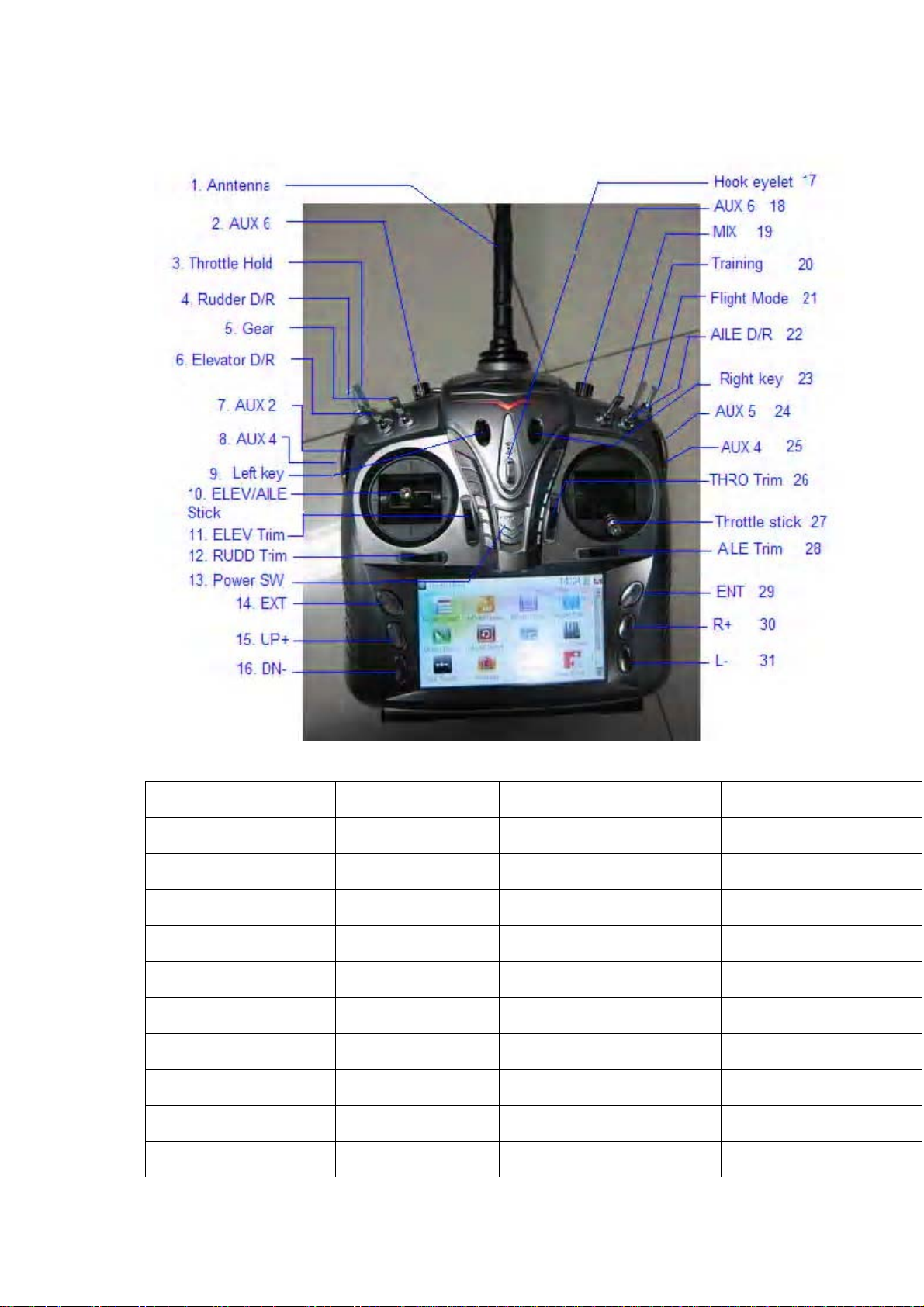
4.1 Panel definition
N/O English Your language N/O English Your language
1 Antenna 17 Hook eyelet
2 AUX 6 18 AUX 6
3 Throttle Hold 19 MIX
4 RUDD D/R 20 TRN
5 GEAR 21 FMOD
6 ELEV D/R 22 AILE D/R
7 AUX 2 23 Right key
8 AUX 4 24 AUX 5
9 Left Key 25 AUX4
10 ELEV/AILE Stick 26 THRO Trim
User Manual for DEVO-12 Page 9 of 238
Page 10
11 ELEV Trim 27 Throttle stick
12 RUDD Trim 28 AILE Trim
13 Power SW 29 ENT
14 EXT 30 R+
15 UP+ 31 L-
16 DN- 32
33
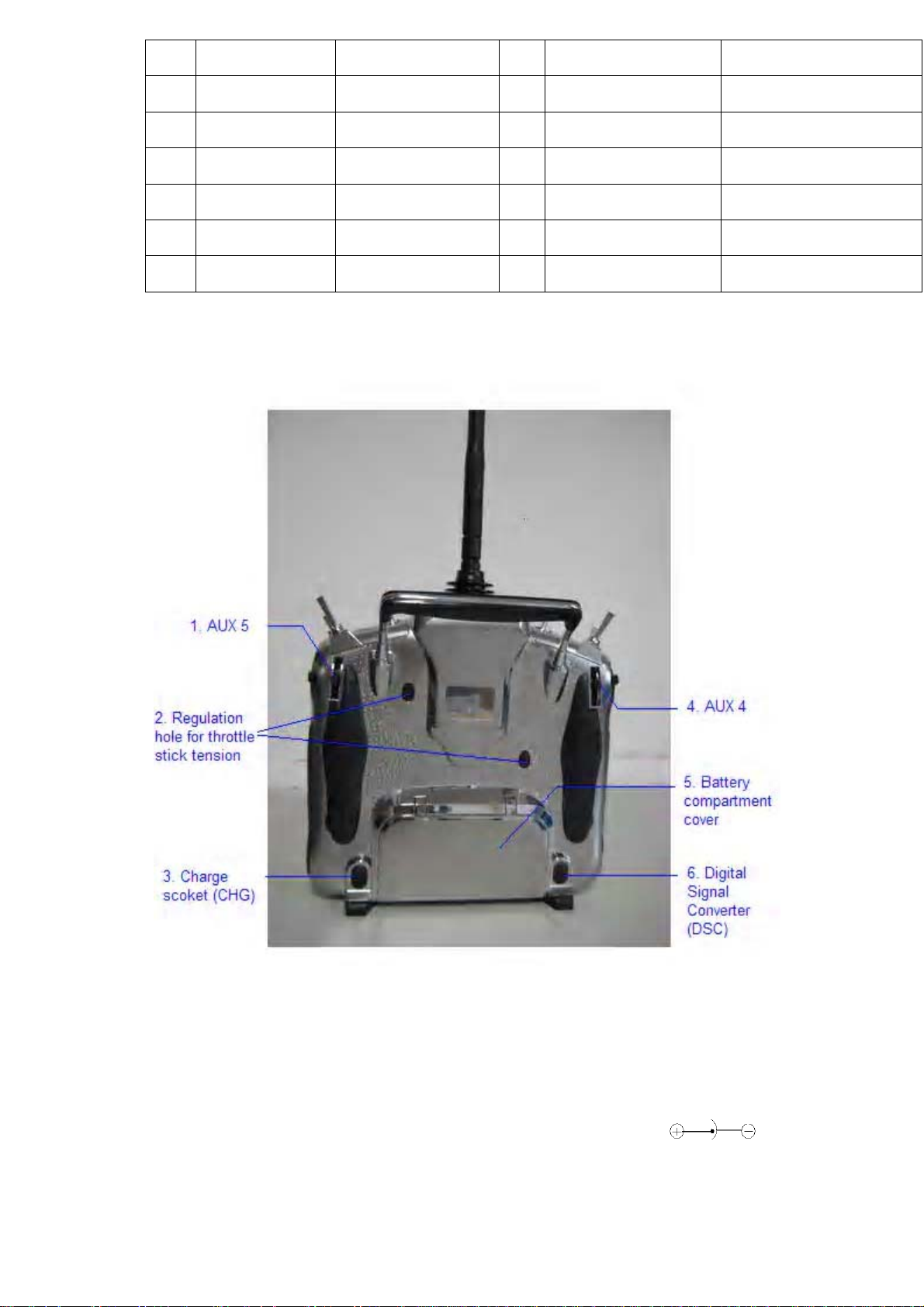
4.2 Rear definition
1. AUX 5
2. Regulation holes for throttle stick tension.
3. Charge socket (CHG): input DC at 5V, 500-1000 mA; Polarity:
4. AUX 4
User Manual for DEVO-12 Page 10 of 238
.
Page 11
5. Battery compartment cover
6. Digital Signal Converter socket (DSC): for simulator flight practice via
computer (You need softw are and its dongle which are available in hobby
shops, and for training.
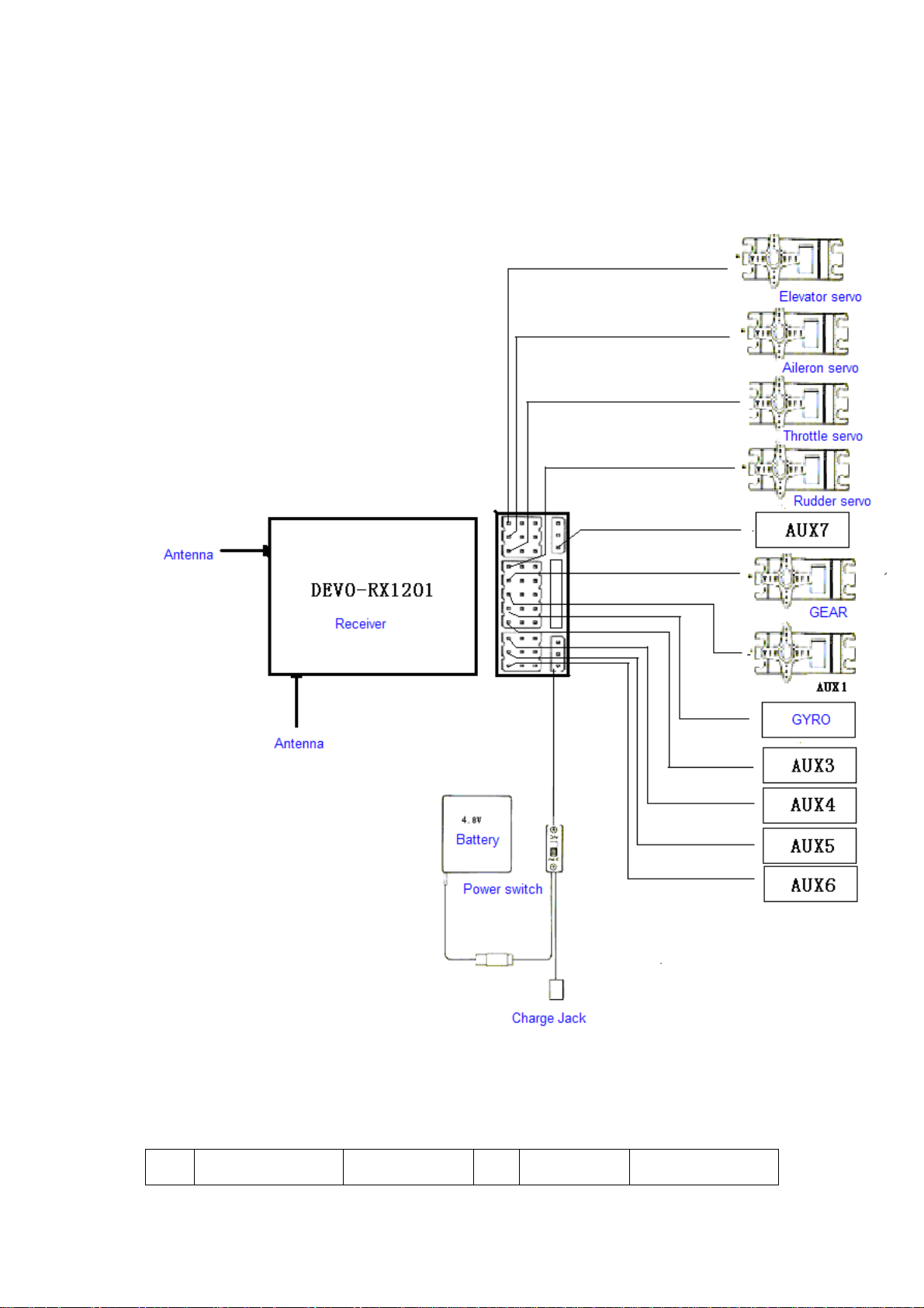
4.3 Wirin g Di a gram
N/O English Your language N/O English Your language
User Manual for DEVO-12 Page 11 of 238
Page 12

1
2 Antenna 11 AUX 1
3 Battery 12 AUX 2
4 Power switch 13 AUX 3
5 Charge jack 14 AUX 4
6 Elevator servo 15 AUX 5
7 Aileron servo 16 AUX 6
8 Throttle servo 17 AUX 7
9 Rudder servo 18
Receiver
DEVO-RX1201
10 Gear servo
4.4 Function keys in panel
There are 6 functional keys in the panel of DEVO-12. Below are the details:
1) EXT: Resetting key. Press EXT to exit the menu.
2) ENT: Confirm ation key. Press ENT to get ac cess to the s ystem or the f unction
mode.
3) UP+: Function-selecting key. Move cursor up to the forward function item.
4) DN-: Function-selecting key . Move cursor down to the next function item.
5) R+: Move cursor rightwards to increase the setting value.
6) L-: Move cursor leftwards to decrease the setting value.
5.0 Control stick adjustment
The control stick adjustment includes parts: control stick length adjustment and
control stick tension adjustment.
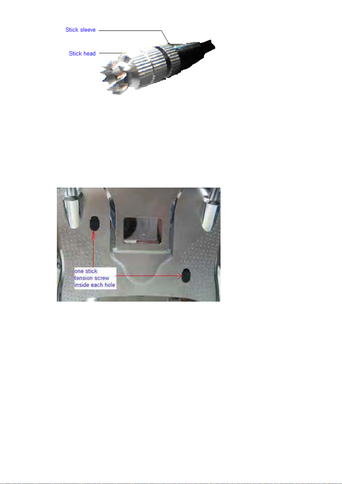
5.1 Control stick length adjustment
1) Prolong the stick leng th: CCW rotate the stic k head until the length you desir e,
and then CCW tighten the stick sleeve.
2) Shorten t he stick l ength: CW rotate the stic k sleeve unti l the leng th you desi re,
and then CW tighten the stick head.
User Manual for DEVO-12 Page 12 of 238
Page 13
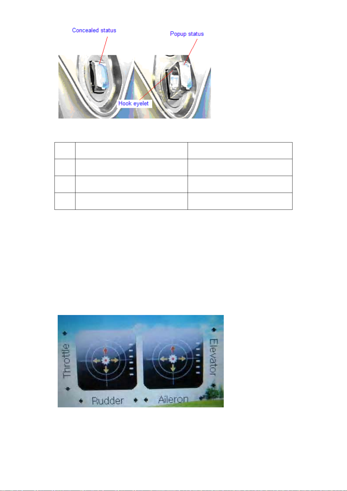
5.2 Control stick tension adjustment
Clockw ise rotate the sti ck tens ion sc rew thr ough the r egul ation hol e in the r are panel
of DEVO-12 for tightening the tension of the corresponding stick by a Phillips
screwdriver, and counterclockwise rotate the stick tension screw for loosening the
tension.
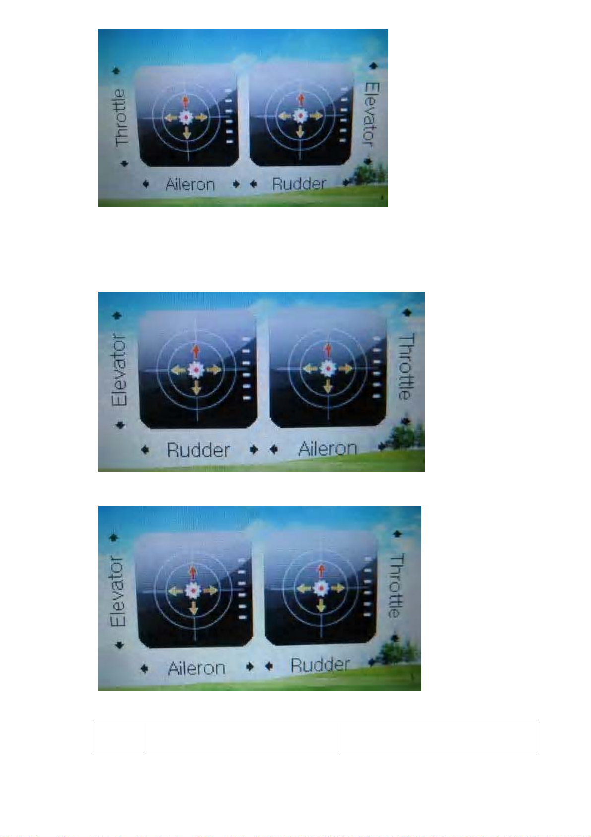
6.0 Neck strap usage
There is a concealable hook eyelet in the face panel of DEVO-12. It will pop up as you
press t he hook eyelet. The neck str ap can be connec ted to the eyelet . The eyelet
located at the center helps to get the best balance of your DEVO-12.
User Manual for DEVO-12 Page 13 of 238
Page 14
English Your language
1 Concealed status
2 Popup status
3 Hook eyelet
7.0 Stick mode switch
There are total four stick modes from MODE 1 through MODE 4. The left-hand throttle
includes M ODE 1 and MODE 3, and the rig ht-hand throttle co ntains MODE 2 an d
MODE 4. Below are the sketch maps:
1) Left-hand stick includes MODE 2 and MODE 4.
MODE 2
MODE 4
User Manual for DEVO-12 Page 14 of 238
Page 15
2) Right-hand stick includes MODE 1 and MODE 3.
MODE 1
MODE 3
English Your language
User Manual for DEVO-12 Page 15 of 238
Page 16
1
Throttle
2
3
4
Rudder
Aileron
Elevator
8.0 Switches between left-hand and right-hand
throttles
The throt tle sw itches b etween th e left hand an d rig ht hand w ill be successful if both
the MECHAN ICAL switch and ELECTRON IC switch are fi nished, separatel y. Below
are the methods for switching.
8.1 Right-ha nd throttle switched to left-hand throttle
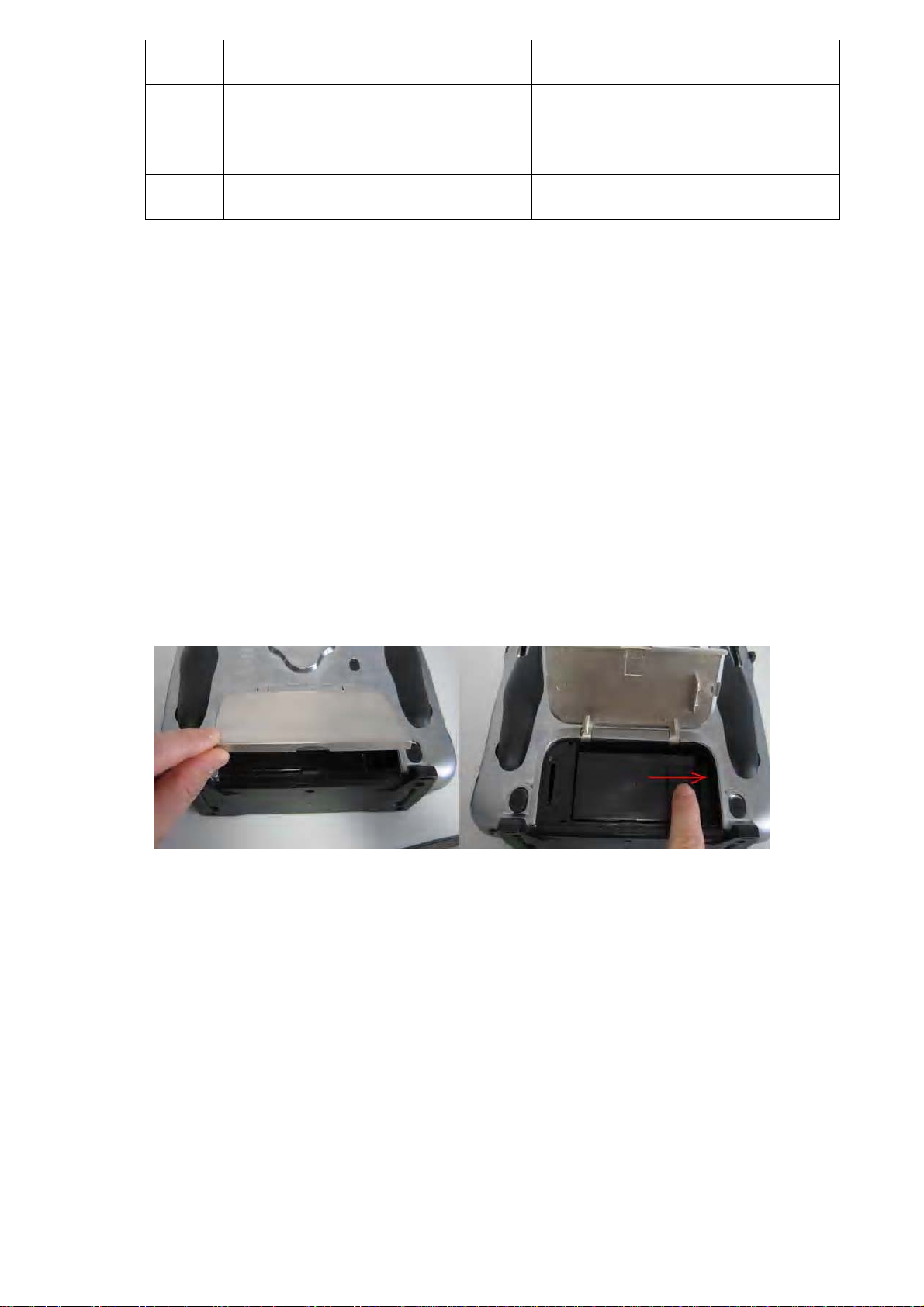
1) MECHANICAL switch
Open the batt ery compar tment cov er in the rear of your DEVO-12. Push rig htwards
and take out the battery pack.
Remove the left lateral, right lateral, and rear non-slipping blocks, respectively.
User Manual for DEVO-12 Page 16 of 238
Page 17
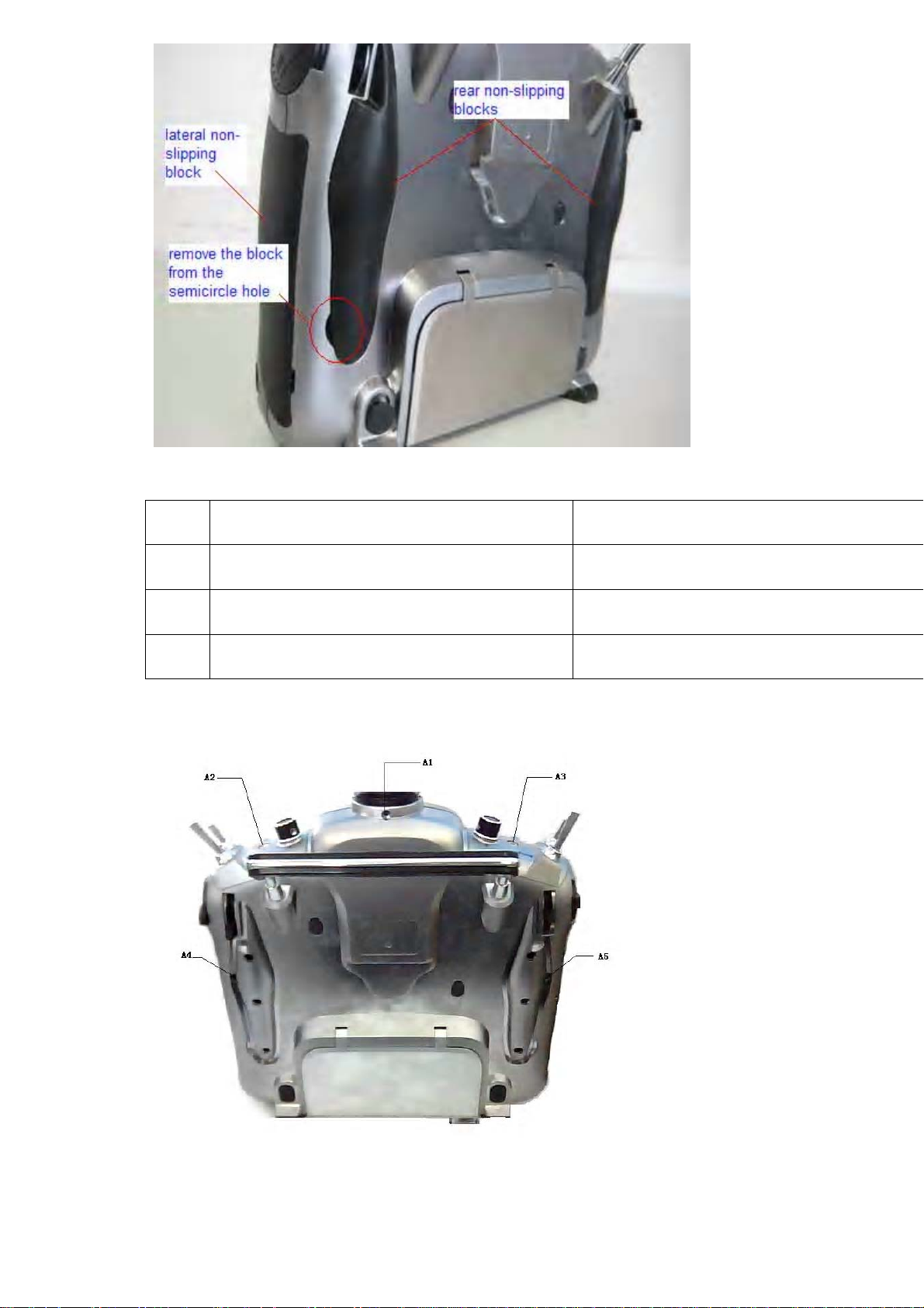
English Your language
1 Lateral non-slipping block
2 Rear non-slipping block
3 Remove the block from the semicircle hole
Remove the fixed screws A1~A5, B1~B5, and then remove the base plate.
User Manual for DEVO-12 Page 17 of 238
Page 18
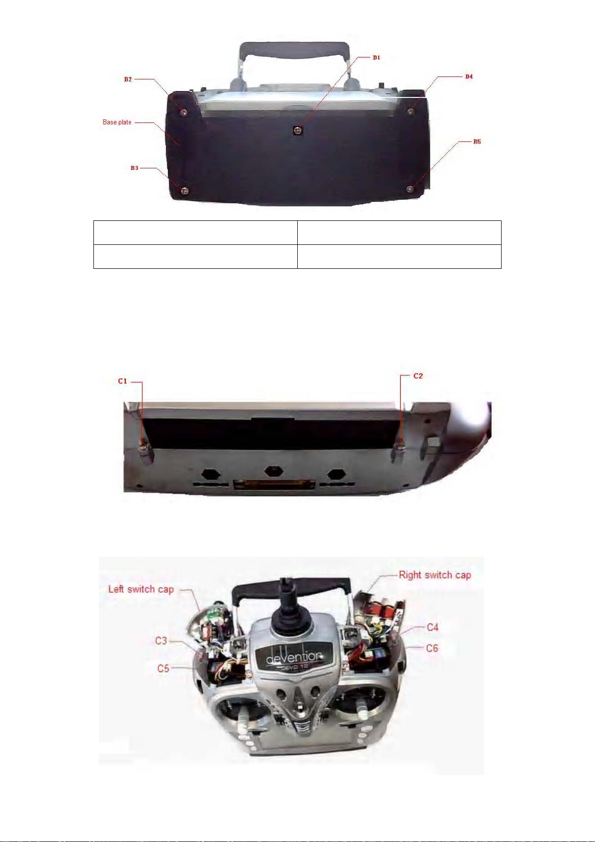
English Your language
Base plate
Remove the screws C1 and C2.
Open the left and right switch caps, respectively, and then unscrew the screws C3 and
C4. And remove the rear cover. Note: don’t break the wires inside.
User Manual for DEVO-12 Page 18 of 238
Page 19
English Your language
Left switch cap
Right switch cap
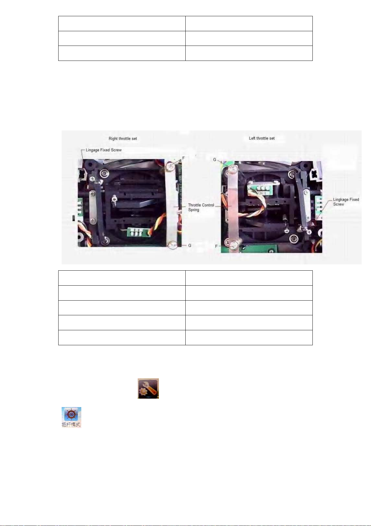
Below are shown the inside views of left and right throttle sets, respectively. Use cross
screwdriver to loosen and remove Linkage Fixed Screw, Screw F, Screw G, and
Throttle Contr ol Spring in rig ht throttle set, r espectivel y, an d then mount them in the
corresponding positions in left throttle set. And then adjust the stick tension according
to your habit.
English Your language
Right throttle set
Left throttle set
Linkage Fixed Screw
Throttle Cont rol Spring
2) ELECTRONIC switch
Touch the shortcut icon
to enter System Menu. Touch the shortcut icon
to enter the interface of Stick Mode, and then select the mode you desire.
User Manual for DEVO-12 Page 19 of 238
Page 20
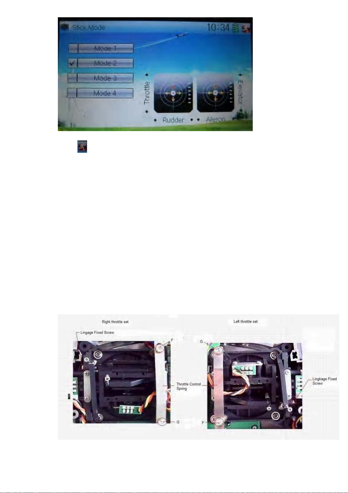
Touch
The switch from right-hand throttle to left-hand throttle is finished after both the
MECHANICAL and ELECTRONIC switches changed, respectively. And the
transmitter is ready to normally work now.
to save and exit after the selection is finished.
8.2 Lef t-hand throttle switched to right-hand throttle
1) MECHANICAL switch
Refer to the above “MECHANICAL switch” to open the transmitter cover.
Below are shown the inside views of left and right throttle sets, respectively. Use cross
screwdriver to loosen and remove Linkage Fixed Screw, Screw F, Screw G, and
Throttle Con trol Spring in left throttle set, respectively, and then mount them in the
corresponding positions in right throttle set. And then adjust the stick tension
according to your habit.
2) ELECTRONIC switch
User Manual for DEVO-12 Page 20 of 238
Page 21
Touch the shortcut icon to enter System Menu, and then touch the icon
to access to Stick Mode.
The model data will be automatically switched when touching MODE 1 or MODE 3.
The left- an d right-stick posi tions are shown, res pectively, in the lower rig ht corner
when MODE 1 is selected.
The left- an d right-stick posi tions are shown, res pectively, in the lower rig ht corner
when MODE 3 is selected.
Touch
to save and exit after the selection is finished.
The switch from left-hand throttle to right-hand throttle is finished after both the
MECHANICAL and ELECTRONIC switches changed, respectively. And the
transmitter is ready to work normally.
User Manual for DEVO-12 Page 21 of 238
Page 22
Note: pay attention to the strength when removing and adjusting the screws.
Excessive strength may damage them.
9.0 Training function
Two DEVO-12 working together can execute the training function to meet the
requirements for the beginners. The setting method is shown as below:
1) Data copy
Using the wirel ess copy function of the tw o DEVO-12 transmi tters, the model data
saved in the trainer ’s transmitter can be transmitted to the trainee’s to ensure the
model parameters are exactly same. Regarding the copying method, refer to 2.4
Model Wireless Copy at “Part Two: Helicopter”. Then fallow the steps below:
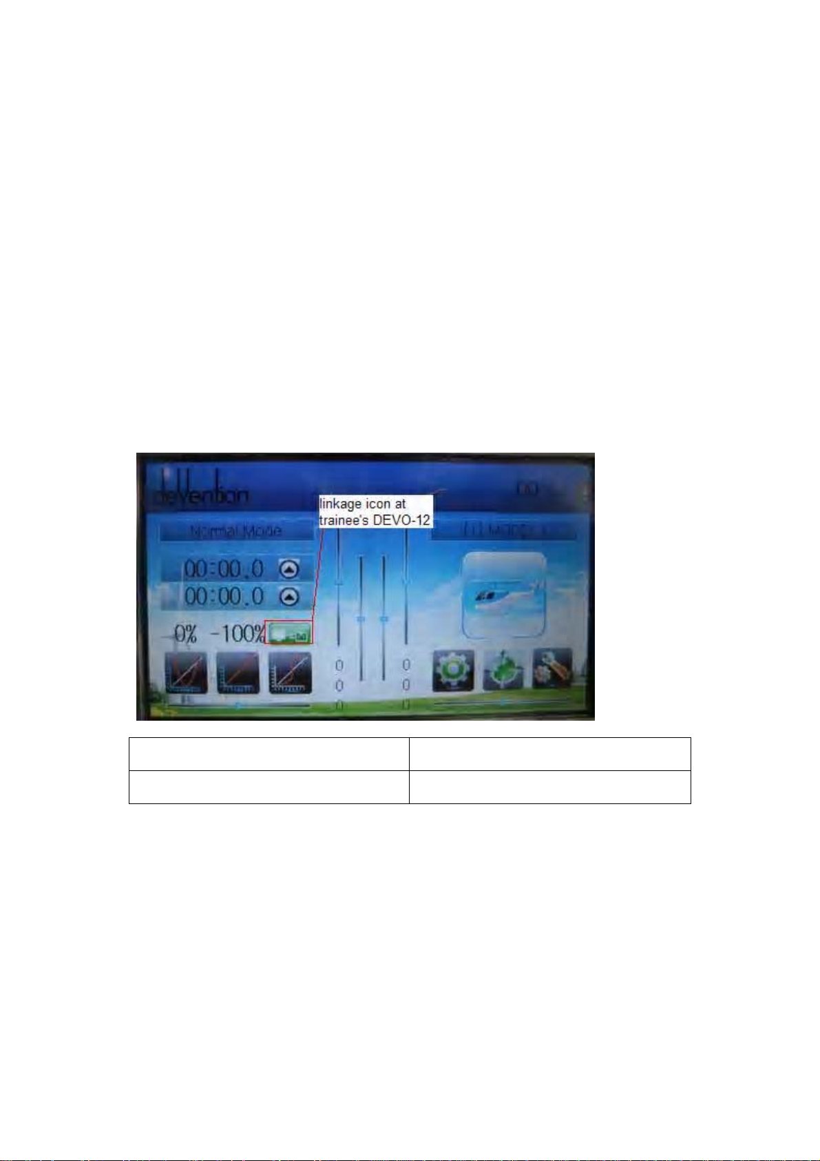
2) Linkage
Insert one end of the sig nal wire into D SC socket at t he rear face of the trainee’s
DEVO-12, and then turn on the power. A linkage icon will be shown on t he boot screen.
Find out the trainee’s model data.
English Your language
Linkage icon at trainee’s icon
Turn on the power of the trainer’s DEVO-12. Find out the trainee’s model data, and let
the trainer’s DEVO-12 fly the aircraft model normally . Then turn off the power.
Insert the other end of the digital signal wire into the trainer’s DEVO-12, and then turn
on its po wer. A linkage icon will be shown as below:
User Manual for DEVO-12 Page 22 of 238
Page 23
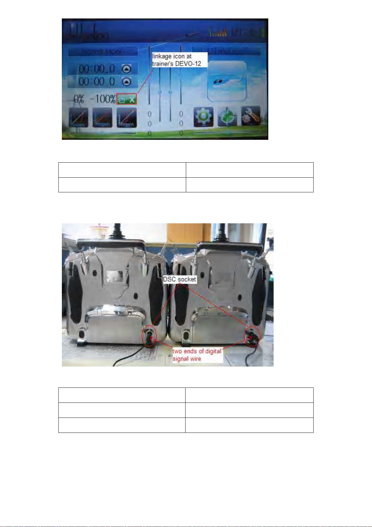
English Your language
Linkage icon at trainer’s DEVO-12
English Your language
DSC socket
Two ends of digital signal wire
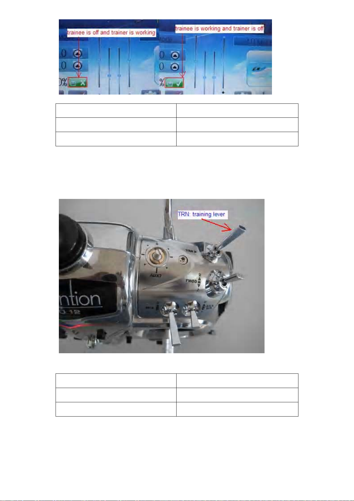
Training status disp lay: when the trainer ’s icon becom es into “X”, the trainee stops
flying and the trainer is working; when the trainer’s icon turns into “√”, the trainee is
flying and the trainer is in leisure.
User Manual for DEVO-12 Page 23 of 238
Page 24
English Your language
Trainee is off and trainer is working
Trainee is working and trainer is off
3) Usage method
The traini ng sw itc h should b e w ork ed with t he TRN tr aini ng lev er, which i s located at
the right top of DEVO-12.
English Your language
TRN: training lever
If the tr ainer ’s f inger pulls the tr aining lever TRN, a “√” is shown in the linkage icon,
whic h means the trai nee is c ontrolling the flight; if the trainer releases his finger from
the tra ine r lever, an “X” will be sho wn the re, which means the trainee stops controlling.
User Manual for DEVO-12 Page 24 of 238
Page 25
4) Setting for training function channels
Trainee is avai lable to get full or part of flight c ontrol power to the aircraft m odel via
setting the traini ng function chan nel in the trai ner’s DEVO-12. Below is the setting
method:
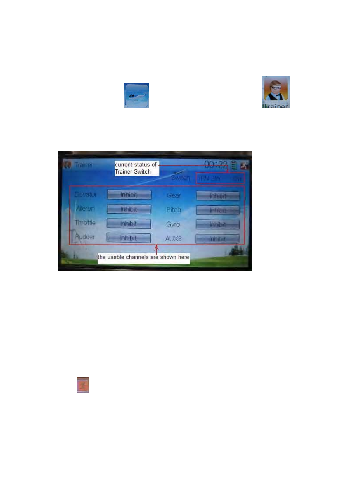
Touch the shortcut icon
in Function M enu to g et acces s to Trainer s creen. The av ail able c hannels ar e show n
below, and the current status of trainer switch TRN is also shown.
to enter Function Menu, and then touch
English Your language
Current status of Trainer Switch (TRN
SW)
The usable channels are shown here
Touc h the channel( s) which you desi re to grant t o trainee. The c hannel(s) you have
touched will be activated as “Active”. The channels which are not granted to trainee
will be kept inhibited. The defau lt setting is “Inhibit”.
Touch
to save and exit after finished.
10.0 Customized fixed ID
This setting will bind DEVO-12 and its receiver in a unique corresponding relationship.
It will greatly speed up the time of automatic binding when DEVO-12 powered on.
User Manual for DEVO-12 Page 25 of 238
Page 26
1) Setting for fixed ID
The setting for fixed ID should be under the status that automatic ID binding is
successfully finished. Below is the setting method.
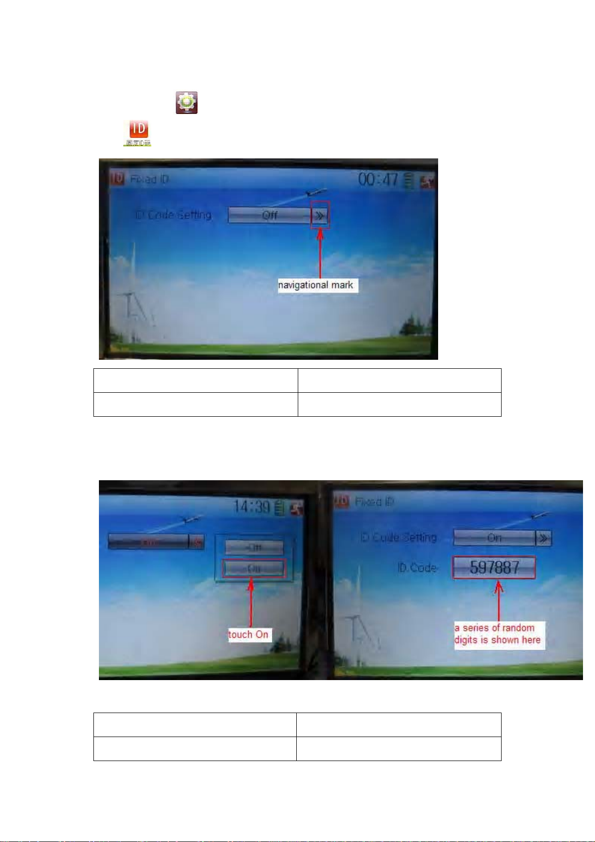
Touc h the i con
icon
in Model Menu.
to e nter M odel Menu, and then ent er Fi xed ID by t ouching the
English Your language
Navigation mark
Touch the navigation mark of the ite m ID Code S et ting. It will expand into two statuses:
Off and On. A series of random digits will be shown below after touching On.
English Your language
Touch “On”
User Manual for DEVO-12 Page 26 of 238
Page 27
A series of random digits is shown here
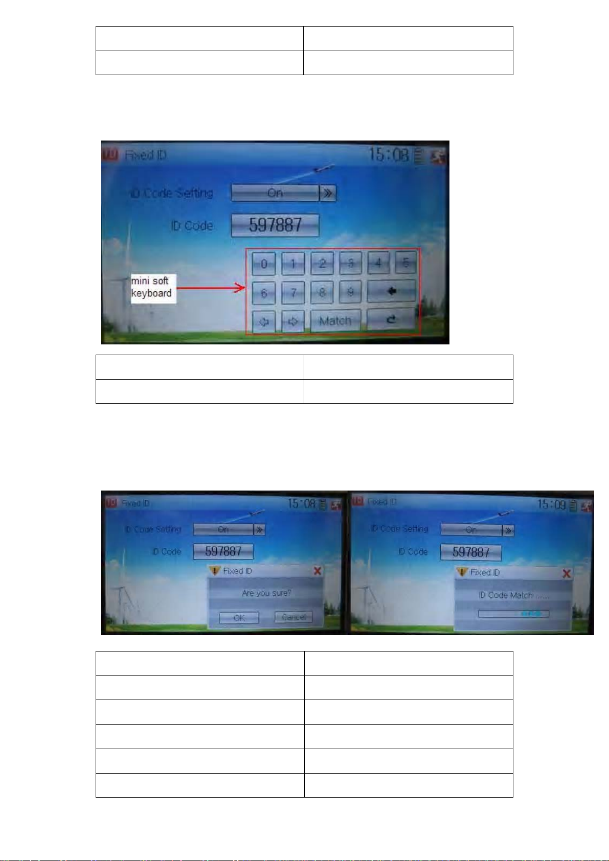
A mi ni soft keyboar d is show n in the low er part after touchi ng the r andom digi ts of ID
Code
English Your language
Mini soft keyboard
The new ID dig its can be m odif ied by to uching the mi ni soft keyb oard. Touch Match
after the n ew ID i s already se t. An enq uiry interf ace of “A re you s ure?” pop up . “ID
Code Match … …” will be shown after touching OK.
English Your language
ID Code Setting
ID Code
Fixed ID
Are you sure?
Cancelled
User Manual for DEVO-12 Page 27 of 238
Page 28
ID Code Match
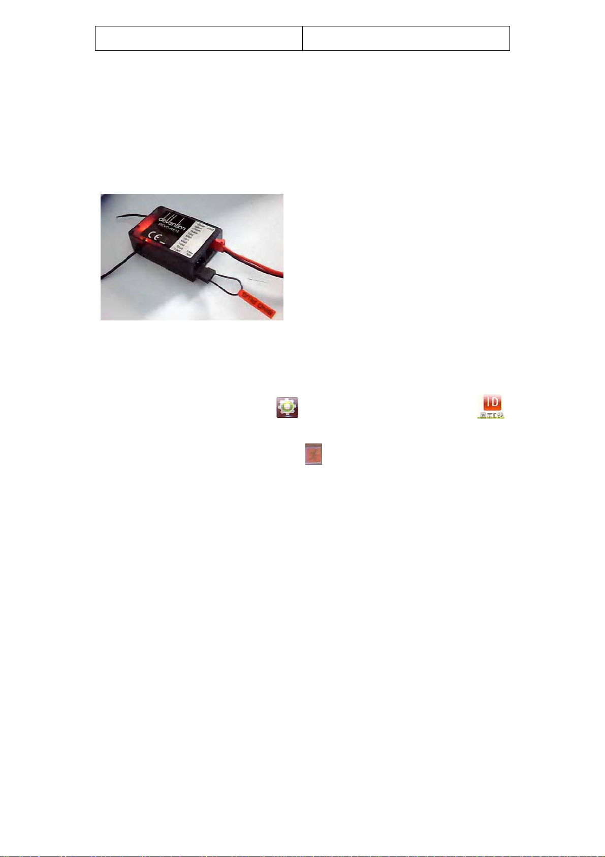
2) Fixed ID cancellation
Insert the assorted BIND PLUG into the output terminal of BATT before the receiver is
powered on, and t hen pl ug 5V DC p ower into oth er output term inal. The red li ght of
receiv er will fl ash slowl y. This m eans the fi xed ID c ode has been c ancell ed. Pull out
BIND PLUG.
DEVO-12 als o needs t o m ake rel ative c ancell ation and r ever si on after the f ixed ID in
receiver is cleared out.
In the m ai n i nter face touc h the ico n
to enter Fixed ID. Touch ID Code Setting to expand the navigation mark into two
statues On and Off. Touch Off. Then touch
to enter M odel Menu and then touch
to exit.
11. 0 Installation requirements for receiver
It is im portant to cor rectly mount your transm itter system i n your model . Below are
some advices on how to install your equipments.
1) Wrap the r ec eiver with 10m m thick foam and soundly fix i t w i th a r ub ber or m agi c
string on your aircraft model. It helps protect the receiver from damage.
2) It is necessary to use rubber grommets and copper sleeves to isolate the
vibrati ons from the main b ody of air craft model . The mounti ng scr ews cannot b e
over-tightened. Otherwise the rubber grommets will be distorted and decrease the
vibration absorption effect.
3) When mounting the servos, make sure the servos’ bellcranks can move freely
over their whole travel range and ensure the control linkages don’t touch or
impede the movement of these servos.
4) If installing various switches, keep them far away from the engine tuned pipe and
high vibration sources. Ensure all the switches move freely over their whole travel
range.
5) Don’t make the receiver antennas wrapped or parallel.
User Manual for DEVO-12 Page 28 of 238
Page 29
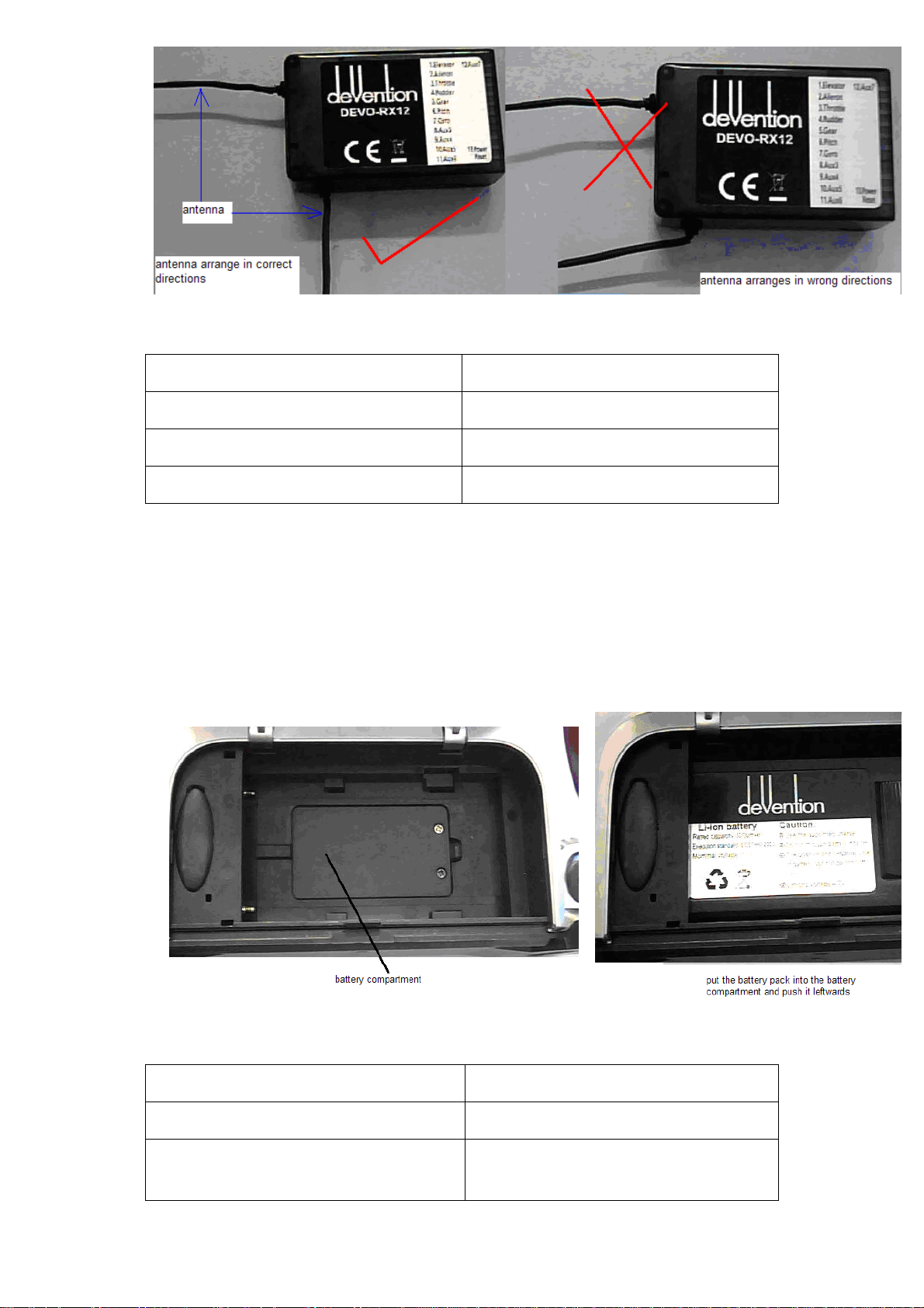
English Your language
Antenna
Antenna arranges in correct directions
Antenna arranges in wrong directions
12.0 Installation requirement for DEVO-12 Battery
pack
Put the batt ery pack int o t h e b att ery com par tm ent i n a c or r ec t p os i ti on an d then push
it left wards.
English Your language
Battery compartment
Put the battery pack into the battery
compartment and push it leftwards
User Manual for DEVO-12 Page 29 of 238
Page 30
12.1 Matters needing attention on battery pac k
1) Forbidden to disassemble battery pack in any case.
2) Forbidden to use or save the battery pack under such high temperature
environment as fir e, heater, strong sunshine, or c ar. Otherwis e superheat, f ire,
functional decline or lifetime dumping may happen.
3) Forbi dden to sink the batter y pack in water, also for bidden to be affected w ith
damp.
4) Forbidden to make a short circuit between anode and cathode of battery pack.
5) Forbidden to use damaged battery pack. The battery pack with electrolyte leaking
or smelling should be aw ay from fire in order to avoid firing or explosion. He
should be washed with water and sent to see a doctor immediately in case of the
leaked electrolyte caught skin, eyes, or other part of body .
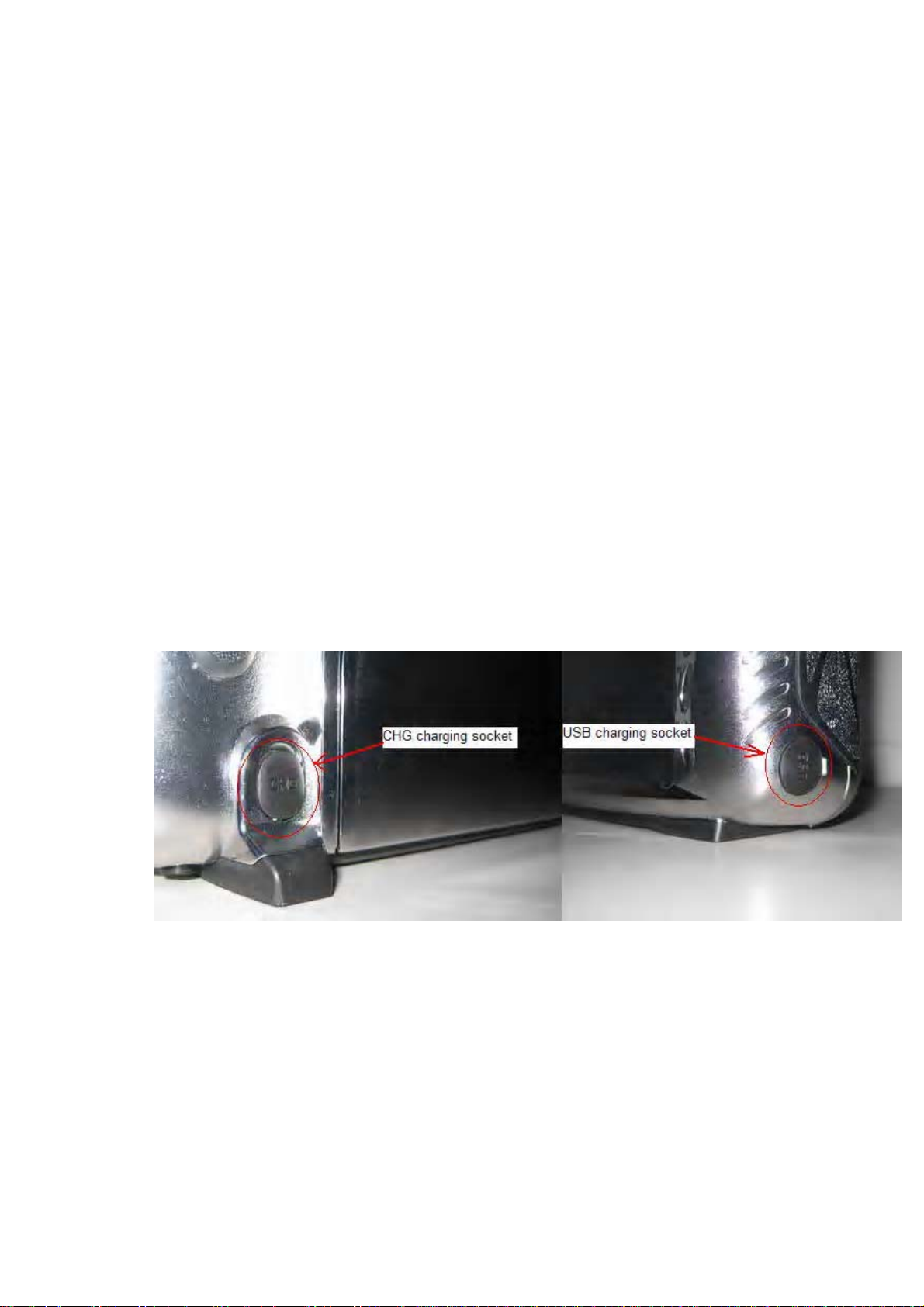
12.2 DEVO-12 battery charging
DEVO-12, which is equipped with build-in charging circuit, is powered by 3.7V
3000mAh Lithium Polymer battery. It begins to charge when the output pin of the
assorted power adapter is inserted into CHG socket, or the normal end of USB
connecting line is connected to the computer USB interface, and the mini end is
inserted into USB in the side face of DEVO.
Charging connection is shown as below:
User Manual for DEVO-12 Page 30 of 238
Page 31

English Your language
CHG charging socket
USB charging socket
Being charged by adapter
Being charged by mini USB
12.3 Voltage p ar ameters
Output of assorted power adapter ……………….. 5.0V 2000mA
Maximum current of CHG socket …………………700mA
Maximum current of USB interface ……………….350mA
12.4 Indication for charging status
There is a slim V-shape indicator light at the top center of DEVO-12. It indicates three
different working statuses from left to right:
0.1) Charging indicator light: blue light is lighting;
0.2) Power-on status of DEVO-12: red light is lighting;
0.3) Saturation level of charge: green light is lighting when the battery pack is
unsaturated; green light is extinguished when saturated.
User Manual for DEVO-12 Page 31 of 238
Page 32

English Your language
Charging indicator light in blue
Power-on indicator light in red
Saturation level light in green
1) Charging at power-on status:
1.1) Charging indicator light: blue light is always lighting;
1.2) Power-on indicator light: red light is always lighting;
1.3) Saturation lev el indic ator lig ht: the gr een lig ht is alw ays lighti ng if the batter y
pack is unsaturated; the green light is extinguished if saturated.
2) Charging at power-off status:
2.1) Charging indicator light: blue light is always lighting;
2.2) Power-on indicator light: red light is extinguished;
2.3) Saturation level indicator light: the green light is lighting when the battery pack
is unsaturated; green light is extinguished when saturated.
Part two: Heli copter
1.0 System menu
All the functional settings, w hich are relative to the op eration systems of DEVO-12
itself, ar e wholly int egrated in S ystem Menu. They include L anguage, Ski n, Disp lay,
Buzzer, Date & Time, TFT Screen, Stick Mode, Stick & Lever,Power Amplif ier, and
User Manual for DEVO-12 Page 32 of 238
Page 33

About.
Below is the boot screen for helicopter:
English Your l anguage Engl i sh Your language
1 Throttle trim 11 Dual rate &
exponential
2 Elevator trim 12 Model menu
icon
3 PIT hover trim 13 Gyro sensor
icon
4 Flight mode 14 System menu
icon
5 Timer 15 Function menu
icon
6 PIT percentage
16 Model name
value
7 Throttle
percentage
value
8 Throttle curve
icon
9 Pitch curve
icon
User Manual for DEVO-12 Page 33 of 238
17 Battery volume
display
18 Time display
19 Transmission
power d i splay
Page 34

10 Rudder trim 20 Throttle hover
trim
1.1 Lan gu a g e set t ing
Touc h the shortcut ico n to e nter System M enu and then touch to enter
the interface of Language. Touch the language that you want to select. A “√” will be
shown on the screen after selected.
Then touch
to save and exit.
1.2 Skin selection
DEVO-12 offers three skins for your selection.
Touch
to enter System Menu and touch to enter Skin.
Touch the skin you desire and then touch
User Manual for DEVO-12 Page 34 of 238
to exit.
Page 35

1.3 Display
Touch the shortcut icon to enter System Menu and then touch the icon
to enter “Display”.
Five items are available to be set. Below are the setting methods for them:
1) LCD brightness: it is possible to increase or decrease the LCD brightness by
touching the n avigation mar ks. The power consumption wil l be increased i f the
LCD is too bright and the battery cruise duration will also be shorten ed .
2) LCD contrast: the con trast is adjustab le by touching the nav igation marks . The
power consumption w ill be increased if the contrast i s too high and the battery
cruise dura t ion will be shortened.
3) Backlight lightness: the backlight lightness is adjustable by touching the
navigation marks. The power consumption will be increased if the backlight
lightness is too bright and the battery cruise duration will be shortened.
4) Backlight time out: it is possible to set the duration which LCD stays at highlight in
the form of “A lways on” or any peri od from 5 to 60 sec onds wi th an interv al of 5
seconds.
5) Pow er save time: it c an adjust the duration w hich turns off the b acklight light i n
order to prolong the battery cruise time. The setting status contents Always on and
30 grades with an interval of 1 minute.
Touch
to exit.
User Manual for DEVO-12 Page 35 of 238
Page 36

1.4 Buzz er warnin g
Touc h the i con to enter S ystem Menu an d the n touc h to enter
the interface of Buzzer interface.
1) Buzzer switch: touch the navigation mark at Buzzer Switch and pop up an
alternativ e item: Off and On. If touching On, a drop -down m enu is shown at the
right upper.
2) Throttle stick buzzer: if Throttle Stick is set as “Active” while Buzzer Switch at On,
a relativ e m usic al scal e chang e w ill be made w hen m oving the t hrottl e s tick . You
can judge the position of the throttle stick according to the different musical scales.
It can also be set as “Inhibit” to silence the musical scales.
3) Levers and knobs buzzer: under the condition that this item is set as “Active”,
DEVO-12 will sound when rotating or moving such levers or knobs as AUX2,
AUX3, AUX4, AUX5, AUX6, and AUX7 to their neutral positions. It can also be set
as “Inhibit” to silence the musical scales.
4) Buzzer tone: the tone is composed of 10 grades. You can choose the favorite one
according to your interests. Touch Test to make a listening test.
Touch
to exit after finished.
1.5 Date & Time
Touc h the icon to ent er System Menu and then t ouch to enter
the item of “Date & Time”.
User Manual for DEVO-12 Page 36 of 238
Page 37

The clock s etting is g rouped into Year, Month , Day, and Time. Touc h the nav igation
marks, respectively, to make modifications.
Touch
to save and exit.
Note: if incorr ect t ur n- on or p r oduc ti on t ime appears, one possi b ility is that the power
supply for the clock is not enough. Replacing a new button cell is a must.
The method for changing button cell:
Turn off the power of your DEVO-12 and take off its battery pack. Use a cross
screwdriver to remove the two fixing screws on the fixing board.
English Your language
Fixing screws
Push outwards the button cell holder, and the button cell will automatically pop up.
Replace the old cell with a new one.
User Manual for DEVO-12 Page 37 of 238
Page 38

Cell size: CR 1220 3V
English Your language
Button cell holder
Push outwards
1.6 TFT scr een calib rat ion
Touch the icon to enter System Menu and then touch to
enter the interface of TFT Screen Calibration.
Click anywhere on the s creen to start c alibr ation wi th the touch pen, and t hen fol low
the indication to calibrate. It will automatically return to System Menu after the
calibration is finished.
User Manual for DEVO-12 Page 38 of 238
Page 39

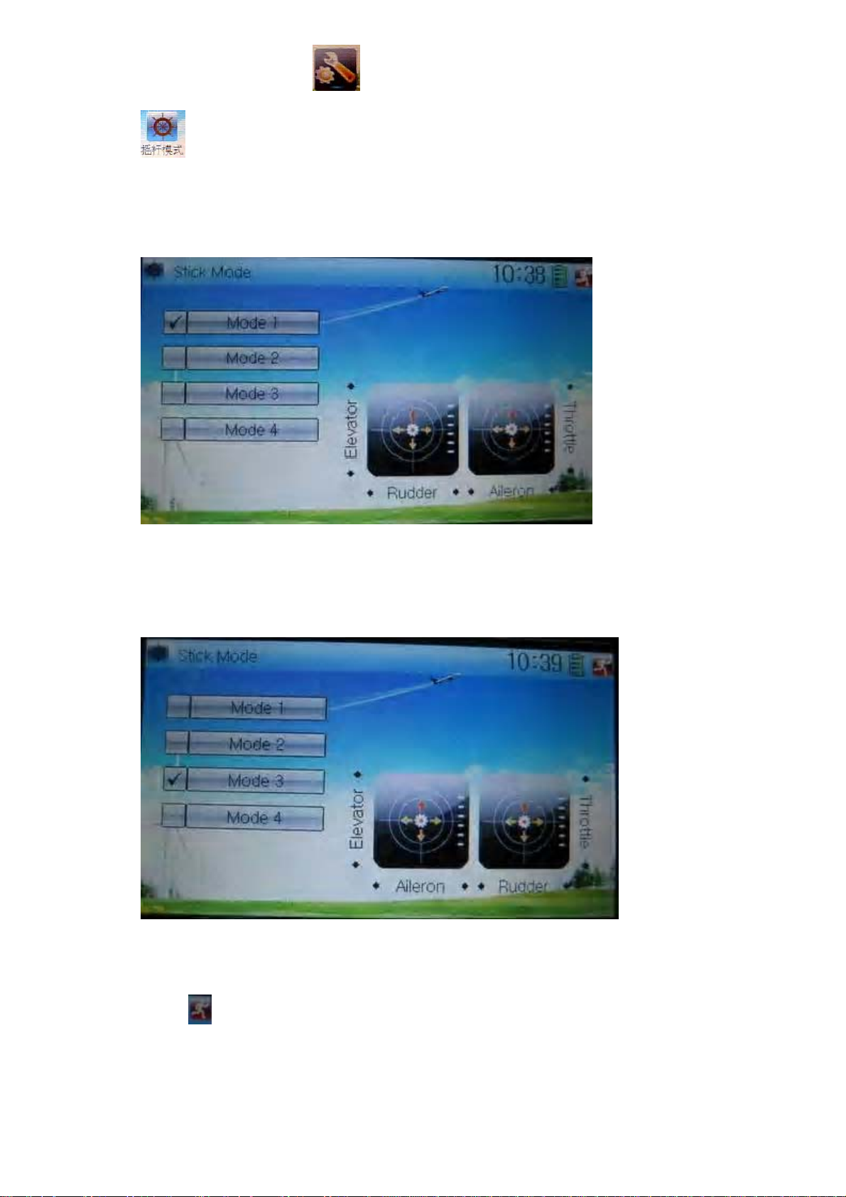
1.7 Stick mode
Touc h the icon to enter System Menu, and the n touch the i con
to enter the interface of Stick Mode.
There are four stick modes from MODE 1 to MODE 4. Select the stick mode you
desire and then touch the icon
to exit.
1.8 Stick and lever
Touc h the icon to enter System M enu and then to uch the icon
to enter the interfac e of Stick and Lever. There are tw o items in the i nterface: Sti ck
Direction and Stick & Lever Calibration.
1) Stick direction: there are four options: Elevator, Aileron, Throttle, and Rudder.
Click the i tem, which you want t o reverse, to change t he output direction of the
User Manual for DEVO-12 Page 39 of 238
Page 40

stick. The default setting is Normal.
2) Stick & lever calibration: if variance happened in sticks or levers, it would be
calibrated via this option.
Method for calibration:
Click the display item of Start to enter the status of calibration, and Start will be turned
into Stop.
2.1) Stick calibration: Clockwise or counter clockwise mechanically move the right
stick and l eft stick from their minim um levels to their m aximum levels s everal tim es,
and then return the sticks to the neutral positions, respectively.
2.2) Lever calibration: mechanically move the levers of AUX2, AUX3, AUX4, and
AUX5, respectively, from the minimum level to the maximum level several times, and
then return to the neutral positions, respectively.
2.3) Cli ck the item of Stop. If the calib ration is fi nished, “C alibrat ion success! ” will be
shown at the low er of the sc r een. If the c al i b r ati on i s f ai l ed, “ C ali bration er r or! Pleas e
try again!” will be shown instead. It needs to be calibrated again.
User Manual for DEVO-12 Page 40 of 238
Page 41

English Your language
Normal
Reverse
Stick direction
St ick & lever calibration
Start
Stop
Calibration su ccess
Calibration error! Please try again!
2.4) Re-c alibr ation: direc tly rep eat the sai d st eps 2.1 and 2.2 i n the cal ib rati on fai lur e
interface.
Touch the icon
to exit.
1.9 Power amplifier
The transmissi on output power of DEVO-12 is adjustable. It i s di vided into s i x g rades
from small to big . The low er the t ransm iss ion outp ut pow er tr ansm its, the shor ter t he
radio rang e is, and the l onger the stand-b y time w ill be. The hig her the tr ansmi ssion
output power, the farer the radio range, and the shorter the stand-by time. Choose the
appropriate transmission output power according to the actual situation.
Setting method:
Touch the icon
interface of Power Amplifier.
to enter System Menu and then click to enter the
User Manual for DEVO-12 Page 41 of 238
Page 42

Choose the appropriate output power level and then touch to exit.
1.10 Ab out
Touch the icon to enter System Menu and then touch to get
access to the interface of About. You can check the versions of hardware and
software.
Click the icon
to exit.
2.0 Model menu
Model Menu manages all the model data saved in DEVO-12. It includes Model Select,
Model Name, Model Copy, Model Transmit, Model Receive, Model Reset, Type Select,
Trim System, Stick Position, Warning, Device Select, Device Output, Swash Type,
and Fixed ID.
2.1 Model select
Touc h t he i c on to enter M odel Menu and then cl i c k t he i c on to enter the
interface of Model Select.
User Manual for DEVO-12 Page 42 of 238
Page 43

Click the model you desired. The selected model will be temporarily changed into
orange color. Then click the icon
to exit.
2.2 Model name
In the m enu of Mod el Nam e, you ca n mak e a desir ed nam e for your m odel f or long
term storage. Its data can be directly withdrawn in next flights.
Repeat the st ep “ 2.1 Model S elect” to c hoose the m odel you want to nam e or save.
And then touch the icon
Click the icon
get the interface of Model Name. The following is the interface:
to exit.
to enter System Menu and then click the icon to
Click the right blank frame of Name and a gray stripe will be shown in the frame.
User Manual for DEVO-12 Page 43 of 238
Page 44

Touch the return key to clear up the old name.
English Your language
Gray stripe
Touch the soft keyboard to input a new name. It is possible to switch between
lowercase and uppercase by clicking the key
Then touch
to exit.
.
2.3 Model copy
Touc h the icon to enter Model M enu and click t o enter Model
Copy.
User Manual for DEVO-12 Page 44 of 238
Page 45

Choose the model you want to b e cop i ed as s our ce model . The ser i al N o. and model
name of Source Model will be shown in the left side of the interface.
Then touch the model in the right list where you want to locate the source model. The
serial No. and name of the model you chose are shown under Dest Model in the lower
left of interface as well as an enquire “Are you sure?” is popped up.
User Manual for DEVO-12 Page 45 of 238
Page 46

Click OK to copy. Otherwise click Cancel. Then the interface will automatically return
to Model Menu. Click
to save and exit.
2.4 Model wireless copy
The model data between two DEVO-12 equipments can be wirelessly copied via
Model Transmit and Model Receive in Model Menu
1) Model transmission
Touc h the icon
to enter Model Transmit.
to enter Model M enu and then c ontinue to c lick the i con
Choose the s ource m odel w hich will be transmitted. The serial No. and name of the
source model will b e s how n under Sel ect M od el i n lef t s i de of the i nt er f ac e as well as
enquiry information “Are you sure?” in the right side.
User Manual for DEVO-12 Page 46 of 238
Page 47

Click OK for transmission or Cancel for rejection. Enquiry information
“Transmitting ……” appears after clicking OK. Touch the icon
to exit.
2) Model receiving
Touc h th e s hor tc ut i c on
to enter Model M enu and t hen touch the i c on to
enter the inter face of M odel R ec eiv e. Enquiry inf orm ati on “ Ar e you sur e?” is s how n i n
the center of the interface.
Click Ok for r ec eivi ng or C anc el f or r ej ec ti on. “ C onnec ti ng ……” and “R ec eiv i ng … …”
will be shown in series in the interface. The information of “Received” with the model
name will be shown in left side after receiving is finished.
User Manual for DEVO-12 Page 47 of 238
Page 48

Choose the save position in the right name list. Enquiry information “Are you sure?” is
shown after c lic k i ng the save pos ition. C li c k OK for save and the curr ent i nterf ace w i ll
automatically return to Mode Menu. Click Cancel for rejection.
Touch the icon
to exit.
2.5 Model reset
All the model data can be restored to factory settings via Model Reset.
Touch the icon
Model Reset.
It is pos sibl e to stor e 60 models data in the m odel l ist of DEVO- 12 equipm ent. There
are two methods to reset the model data: batch reset and single reset.
to enter Model Menu and then click to enter
1) Method for batch reset:
User Manual for DEVO-12 Page 48 of 238
Page 49

Touc h ‘All Model s’ in M odel R eset inter fac e. The n ‘’ All Model s” and enq uiry “Ar e you
sure?” appear in the left side. Click OK for reset, or Cancel for rejection.
2) Method for single reset:
Touch the upper or lower navigation mark to move the scroll bar, and then choose the
model you want to restore in the model name list. All the selected model’s name,
serial No and enquiry “It is in use! Are you sure?” will appear in the left side. Click OK
for resetting, or Cancel for rejection.
Click the icon
to exit.
2.6 Type select
This dev ice of fer s thr ee m odel types m enu. The y are hel icop ter, airp lane, and g lider,
respectively.
Touc h the icon
User Manual for DEVO-12 Page 49 of 238
to enter M odel Menu and then cli ck to enter Type
Page 50

Select.
Choose the model type and then touch the icon
to exit.
2.7 Trim system
Trim System is able to finely tune the following six items, respectively: Elevator,
Aileron, R udder, Throttl e, Left Trim , and Ri ght Trim. The trim r ange is divi ded into 20
grades (factory default is set at 4). It is convenient to subtly modify the pitch by
adjusting the trim range.
Touc h the icon
Trim System.
to enter M odel Menu and then clic k to enter
Touch the corresponding nav igation mark to change the tri m value. The bigg er the
trim value is, the bigger the trim range will be.
For elev ator, aileron, and rudder, there are two more options: Norm al and Limited.
User Manual for DEVO-12 Page 50 of 238
Page 51

“Normal” means the trim is always working although the corresponding stick stays
anywher e. “ Limited” m eans t he tr i m is out of working w hen the corr esponding s ti c k i s
at maximum position.
2.8 Stick position
The stick can b e used as a sw it ch. The t urn- on or t urn- off p ositi on at w hi ch the stic k
stays can also be set table.
Method for setting:
Touch the icon to enter Model Menu and then click to enter
Stick Position Switch.
Click the navigation mark of Switch. It pops up a drop-down menu: SPS0, SPS1,
SPS2, and SPS3. Choose the switch you want to define.
Then touch the navigation mark of Channel. It expands into five items: Inhibit, Elevator,
Aileron, Thr ottle, and R udder. The factory def ault setti ng is Inhib it. Choose the st ick
you want to set as “switch”.
User Manual for DEVO-12 Page 51 of 238
Page 52

English Your language
Stick po sit ion switch
Switch
Channel
Inhibit
Elevator
Aileron
Throttle
Rudder
Choose the c hannel w hich will b e set as
switch.
At the same time, “Position” and the status of turn-on or turn-off appear under the item
Channel. The current status of turn-on or turn-off will be shown in the form of On or Off
on the right top corner.
User Manual for DEVO-12 Page 52 of 238
Page 53

English Your language
Switch sta tus
“Position” and switch status appear under
“Channel”
Click the icon
to exit after the setting finished.
2.9 Warning
This functi on can set the war ning for uns afety of whi ch stick, s witch status, or flig ht
mode stays at the p os it i on while tur ni ng on t h e d evice, or i s use d as start- up warning
in special pur po s e.
In factor y, Throttle Stick is s et as Act ive, Hi g h di r ect ion at 10.0% P os it i on, flig ht m ode
as Stunt, and Throttle Hold at on position.
Touc h the icon
interface of Warning.
User Manual for DEVO-12 Page 53 of 238
to enter M odel Menu and then click to enter the
Page 54

Setting method:
1) setting Throttle stick as warning
Click the nav igat ion mar k of Throttl e Stick in the i nter fac e of Warning. It ex pands int o
Inhibit and Active. If Inhibit clicked, the dropdown menu is retracted. If Active clicked, it
will expand into two sub items: On and Position.
The throttle stick can be set at high or low position when startup is warning, via
clicking the navigation mark of On. The warning level can be set by changing the
percentage in Position, whose setting value is ranged from 0.0 to 100.0%.
Take t he ri ght- hand thrott le as an exam p le. Positi on is 0.0% w hen the thrott le sti ck i s
at the lowest position; Position is 100.0% when the throttle stick is at the highest
position. In factory, Throttle Stick is set as Active, Position in High direction at 10.0%.
2) setting other items
Other flight modes and switches warning is shown in the low er-middle part of the
interf ace. Cli ck the corr espondi ng item s you w ant to us e. Th e factor y def ault setting
includes Stunt 1, Stunt 2, Stunt 3, Stunt 4, and Throttle Hold.
Click
to exit.
2.10 Device select
This setti ng can help you c onfigure v arious func tional switches , or adjust levers. It
includes Flight Mode Main Switch, Flight Mode Extra Switch, Stunt Trim Select,
Throttle Hold Switch, Hovering Pitch, and Hovering Throttle.
Setting method:
Touc h th e i c on
enter Device Select.
User Manual for DEVO-12 Page 54 of 238
to enter M odel M enu, and then cl i c k the i c on to
Page 55

1) Flight Mode Main Switch
Touc h the nav igat ion mark of Flig ht Mode Mai n Switch an d expand i nto a dr opdow n
menu, where to choose the mode switch you desire. The factory default setting is
FMOD SW.
2) Flight Mode Extra Switch
Refer to “Flight Mode Main Switch”.
3) Stunt Trim Select
There are two modes: Common and Flight Mode. In Common mode all the trim values,
which various sticks are corresponding to, put equally effects on all the flight modes.
In Flight Mode, the trim value, which each stick is corresponding to, puts
independently effect on the corresponding stick. The factory default is Common.
4) Throttle Hold Switch
Refer to “Flight Mode Main Switch”.
5) Hovering Pitch
Refer to “Flight Mode Main Switch”.
6) Hovering Throttle
User Manual for DEVO-12 Page 55 of 238
Page 56

Refer to “Flight Mode Main Switch”.
2.11 Device Output
Device output is composed of eight items. It can set up output switches and select the
usage of levers, respectively. It can also activate, inhibit or use other functions.
Setting method:
Touch the icon to enter Model Menu and then click to enter the
interface of Device Output.
There are eig ht adjus table item s. They ar e Gear, Pitch, AUX2, AUX3, AUX4, AUX5,
AUX6, and AUX7, respectively . The setting methods for them are shown below:
1) Gear
Touc h the l eft c ol umn navig at i on m ar k of Gear and p op up an expansi on l i s t i nc ludi ng
FMOD SW, MIX SW, ELEV D/R, AILE D/R, RUDD D/R, H OLD D/R, and GER A SW.
Touch the desired item. The default setting is GEAR SW.
User Manual for DEVO-12 Page 56 of 238
Page 57

English Your language
Touch navigation mark
Expansion of GEAR SW
Touc h the rig ht column navi gation mar k of Gear. Pop up an expansi on list incl uding
Inhibit, Active, Gyro, Governor, and Pitch 2. Touch the desired item. The default
setting is Active.
English Your language
Right column navigation mark
Expansion list
1) Pitch
The item is programmed as system default. Any setting is unavailable.
2) AUX 2
Touc h the l eft colum n navi gation m ark of AUX 2. P op up an expansion list i ncluding
SPS0 SW, SPS1 SW, SPS2 SW, SPS3 SW, Left Tr im, Rig ht Trim, and AU X2 Lever.
Touch the desired item. The default setting is AUX2 Lever.
User Manual for DEVO-12 Page 57 of 238
Page 58

Touch the right column navigation mark of AUX 2, and expands a list including Inhibit,
Active, Gyro, Governor, and Pitch 2. Click the desired item. The default setting is
Active.
Then continue to set other items.
3) AUX 3
Touch t he left col um n navigat ion mar k of AU X 3, and expands a list i ncludi ng AUX3
Lever, AUX4 Lever, AUX5 Lev er, AUX6 Knob, AXU7 Knob. Touch th e desired i tem.
The factory default setting is AUX3 Lever.
User Manual for DEVO-12 Page 58 of 238
Page 59

Click the right column navi gation mark of AU X3, and see a expansion list including
Inhibit, Active, Gyro, Governor, and Pitch 2. Choose the desired item. The factory fault
setting is Active. Then continue to set up other items.
4) AUX 4
Refer to “4) AU X 4”.
5) AUX 5
Refer to “4) AU X 4”.
6) AXU6
Refer to “4) AU X 4”.
Click the icon
to exit.
2.12 Swash type
The swash type is grouped into six options: 1 Servo Normal, 2 Servos 180°, 3 Servos
140°, 3 Servos 140°, and 4 Servos 90°.
User Manual for DEVO-12 Page 59 of 238
Page 60

Setting method:
Touc h the icon
to enter the interface of Swash Type.
Choose the desired swashplate and then click the icon
to enter Model M enu, and t hen cli ck the icon
to exit.
2.13 Fixed ID
This setting will bind DEVO-12 and its receiver in a unique corresponding relationship.
It will greatly speed up the time of automatic binding when DEVO-12 powered on.
1) Setting for fixed ID
The setting for fixed ID should be under the status that automatic ID binding is
successfully finished. Below is the setting method.
Touc h the icon
by touching the icon
to enter Model M enu, and the n enter the interf ace of F ixed ID
.
User Manual for DEVO-12 Page 60 of 238
Page 61

English Your language
Navigation mark
Touch the navigation mark of the ite m ID Code S et ting. It will expand into two statuses:
Off and On. A series of random digits will be shown below after touching On.
English Your language
Touch “On”
A series of random digits is shown here
A mi ni soft keyboar d is show n in the low er part after touchi ng the r andom digi ts of ID
Code
User Manual for DEVO-12 Page 61 of 238
Page 62

English Your language
Mini soft keyboard
The new ID digits can b e modified b y touching t he mini s oft keyboard. Then touch
Match after the new ID is already set. An enquiry interface of “Are you sure?” pops up.
“ID Code Match … …” will be shown af ter touching OK.
English Your language
ID Code Setting
ID Code
Fixed ID
Are you sure?
Cancelled
ID Code Match
2) Fixed ID cancellation
Insert the assorted BIND PLUG into the output terminal of BATT before the receiver is
powered on, and t hen pl ug 5V DC power into one of the ot her output ter minal s. The
User Manual for DEVO-12 Page 62 of 238
Page 63

red light of receiver will flash slowly. This means the fixed ID code has been cancelled.
Pull out BIND PLUG.
DEVO-12 als o needs t o m ake rel ative c ancell ation and r ever si on after the f ixed ID in
receiver is cleared out.
In the m ai n i nter face touc h the ico n
to enter Fixed ID. Touch ID Code Setting to expand the navigation mark into two
statues On and Off. Touch Off. Then touch
to enter M odel Menu and then touch
to exit.
3.0 Function Menu
Function Menu can help you make customizedly adjustments for the selected models.
The menu includes such items as Reverse Switch, Travel Adjust, Sub Trim, Dual Rate
and Exponential, Throttle Hold, Throttle Curve, Mix to Throttle, Gyro Sensor, Governor,
Tail Curve, Dual Pitch, Swash Mix, Pitch Curve, Program Mix, Monitor, Fail Safe,
Trainer, and Timer.
3.1 Reverse Switch
Touch the shortcut icon to enter Function Menu, and then click to
enter the interface of Reverse Switch.
The statues of total 12 channels are shown in the interface. T ouch the relative channel
User Manual for DEVO-12 Page 63 of 238
Page 64

for Normal or Reverse switch. The default setting is Normal.
Click the icon
to exit.
3.2 Travel adju st
Touc h the icon to enter Function Me nu and then c lick to enter the
interface of Travel Adjust.
Touch the navigation mark of the desired item to increase or decrease the servo travel
rang. The adjustment range is from 0.0% to 150.0%. The factory default is 100.0%.
Click the icon
to exit.
3.3 Sub Trim
Sub Trim can par allel to move the ne utral point of the servo. But w e advise you to
adjust the servo bell crank if offset is far away from the neutral point of servo, because
excessive usage of the sub trim, out of its range, may damage the servo.
Setting method:
Touch the icon
Trim.
to enter Function Menu and then click to enter Sub
User Manual for DEVO-12 Page 64 of 238
Page 65

It is pos s ibl e t o change the servo neutral point by to uc hi ng the navig ati on m ar k of the
desired item to am end the percentage. The default for each channel is 0.0%. The
following chart shows you the adjustment range of each channel:
Engli sh Y our language English Your language
Channel name Adjustment range
1 Elevator D62.5%-U62.5%
2 Aileron R62.5%-L62.5%
3 Throttle L62.5%-H62.5%
4 Rudder R62.5%-L62.5%
5 Gear -62.5%- +62.5%
6 Pitch L62.5%- H62.5%
7 AUX2 -62.5%- +62.5%
8 AUX3 -62.5%- +62.5%
9 AUX4 -62.5%- +62.5%
10 AUX5 -62.5%- +62.5%
11 AUX6 -62.5%- +62.5%
12 AUX7 -62.5%- +62.5%
Touch
to exit.
3.4 Dual Rate and Exponential
After this f unct ion is set up , it i s possib le for D/R switches to con trol the dual rates of
elevator, ail eron, and rudder, respect ively. The setti ng range is c overed f rom 0% to
User Manual for DEVO-12 Page 65 of 238
Page 66

125%. Under the help w ith ex ponenti al curv e adj ust m ent, it i s p ossi ble t o m ake bot h
customized settings and automatic settings.
The switch between Dual Rate and Exponential can be performed via pushing or
pulling th e Flight Mode lever.
Setting method:
Touch the icon
to enter Function Me nu and then clic k to enter
the interface of Dual Rate and Exponential.
1) Channel selection
Touch the navigation m ark of Channel. An expansion list pops up, which contents
Elevator, Aileron, and Rudder. Choose the desired channel for setting.
English Your language
Expansion list pops up
2) Position selection
Touc h the n avig ati on m ark of Posi t i on. An expans i on l i s t pops up , wher e ther e ar e s i x
points for you choosing from Pos0 through 5. Chose the position you want to set. The
User Manual for DEVO-12 Page 66 of 238
Page 67

chosen point will be shown in the frame of the item Position.
In manual m ode, the functi on of Dual R ate and Exponenti al will be executed by the
corresponding dual rate switch among Pos 0, Pos 1, and Pos 2.
Take t he item El evator at Channel as the exam p le. All the f lig ht modes , shown i n the
right c olumn, are set as “Swi tch” . Then if w e move the lev er of ELEV D /R, the swi tch
will be taken place among Po s 0, Pos 1, and Pos 2.
If moving the le ver EL EV D/R (sho wn above), s witch will h a ppen a mon g Pos 0 , Pos 1,
and Pos 2 (shown below).
User Manual for DEVO-12 Page 67 of 238
Page 68

English Your language
ELEV D/R
“Channel” is set as “Elevator”
All the flight modes are set as “Switch”
The current Switch position is shown here
3) Dual Rate adjustment
It is pos sible to modify the dual r ate value by touc hing the navig ation mark of Dual
Rate.
If touching the navigation mark for just one item to amend the dual rate value, the dual
rate of the c orresp onding s ervo will be c hanged in one dir ection, w hile t he curv e will
being changed in one direction at the right graph.
If touchi ng the nav ig ation m ar k for b oth i tem s to am end the dual rate v al ue, the du al
rate of the c or r es p ondi ng s ervo will be c hang ed w hi le the c ur ve will bei ng c hang ed at
the same time, shown at the right graph. The default setting is 100%.
English Your language
User Manual for DEVO-12 Page 68 of 238
Page 69

Upper curve
Lower curve
If touch this mark, both the upper and
lower curves will being changed at the
same time.
If touch this mark, upper or lower curve
will being changed.
4) Exponential adjustment
It is pos s ibl e t o adj ust t h e ex p onen ti al out p ut value o f the s er vo at that p oint , which i s
set up in step “2) Position selection”, by touching the navigation mark of Exponential.
If touching the navigation mark for just one item to amend the dual rate value, the dual
rate of the c orresp onding s ervo will be c hanged in one dir ection, w hile t he curv e will
being changed in one direction at the right graph.
If touchi ng the nav ig ation m ar k for b oth i tem s to am end the dual rate v al ue, the du al
rate of the c or r es p ondi ng s ervo will be c hang ed w hi le the c ur ve will bei ng c hang ed at
the same time, shown at the right graph. The default setting is Line.
Then touch this mark
to return to the interface of Dual Rate and Exponential.
5) Automatic setting
Under working with Flight Mode, it is possible to switch the dual rate and exponential,
whic h are set in above “ 3) Dual Rate adjus tment” and “4) Exponential adj ustment”,
respectively.
User Manual for DEVO-12 Page 69 of 238
Page 70

The settings for Normal Mode, Stunt 1, Stunt 2, Stunt 3, Stunt 4, and Throttle Hold are
avail able. But for Stunt 3 and Stunt 4, Flig ht Mode Extr a Switch at D evice Selec t in
Mode Menu sho uld b e activ ated ( Ref er to “ 2.10 Dev ice Sel ect” ), and T hrottl e Hold i n
Function Menu should be set as “Active” (Refer to “3.5 Throttle Hold” below).
Touc h the fl ig ht mode that you want t o set as aut omati c op erati on, and an expa nsion
list w ill be show n. Cl ick the desi red p osit ion. If Switch i s selec ted, it i s onl y controll ed
by the corresponding dual rate lever.
Click the icon
to exit.
3.5 Thr ot tle hold
If this function is set, the switch will be executed by hold switch. The setting value of
throttle hold is ranged from -20.0 to 50.0。
Setting method:
Touch the shortcut icon
enter the interface of Throttle Hold.
User Manual for DEVO-12 Page 70 of 238
to enter Function Menu, and then click to
Page 71

Touch the navigation mark of Hold Status, and an expansion list will be shown as
Inhibit and Active. Click Active, there appeared Swi tch, Hold Position, and Throttl e
St ick in the following interface.
vv
1) Setting for Switch
This item is impossible to be set. The default setting is HOLD SW.
2) Setting for Hold Position
Touch the left navigation mark of the item Hold Position to decrease the position
amount, w hose minim um is -20. 0%; touch the r ight to inc rease th e position amount
whose maximum is +50.0%.
3) Setting for Throttle Stick
Given the function is used. If the throttle hold lever is turned on, it is possible to set the
throttle stick as the switch that enters the status of throttle holding.
User Manual for DEVO-12 Page 71 of 238
Page 72

Setting method:
Touc h the navig ation mark of Throttle Stick and an expansion l ist will be shown as
Inhibit and Active. Click Active and pop up a dropdown menu of Cut Position.
Touch the left navigation mark of Cut Position to decrease the amount whose
minim um is 0.0%; touch t he right m ark to increase the amount w hose maximum is
100.0%.
Under the throttle hol d turned on (pull the throttle h old lev er forw ard), when mov ing
the throttle stick to the point set by Cut Position f rom hig h position to low p osi tion, the
throttle e nters the l ocked status . Th at m eans the thr ottl e is l ocked at t he point set by
Hold Position.
If pushing the throttle hold lever, the throttle locked status is released.
Click the icon
to exit after all the settings are finished.
3.6 Thr ott le curv e
Throttle cur ves are adjus ted throug h nine p oints, w hi ch of all the f lig ht modes c an be
User Manual for DEVO-12 Page 72 of 238
Page 73

respectively set. The flight mode includes Normal Flight, Stunt 1, Stunt 2, Stunt 3, and
Stunt 4 while Fl ight M ode Ext r a Switch i n Dev i ce Selec t shoul d be activated (Refer to
“2.10 Device Sele c t”).
Setting method:
Touch the shortcut icon
to enter Function Menu, and then click the icon
to enter the interface of Throttle Curve while an enquiry dropdown is shown
“All Servos Hold?” If click OK, all the servos will be locked at the current status; if click
Cancel, all the servos will not be locked at the current status. Enter the following
interface after clicking OK or Cancel.
1) Adjustment for Exponential
Touc h the navi gation mar k of Exponential and expand a n option dr opdown: Off and
On. The throttle curve will be changed smoothly if touching On, or in fold line if clicking
Off.
2) Curve Setting
It includes two items: Point, and Output.
2.1) Adjustment for Point
Touch the navigation mark of Point and an expansion list including nine points is
shown. Click the point which you want to adjust.
2.2) Status adjustment
User Manual for DEVO-12 Page 73 of 238
Page 74

Touch the navigation mark of Status and drop down a menu including Inhibit and
Active. Click Inhibit if you don’t amend the amount of the selected point which is set in
“2.1 Adjustment for Point” (the factory default setting is Inhibit). Click Active if you want
to amend the amount of the s aid point, and an expansion li st including Out put and
Hovering is shown below.
2.3) Output adjustment
Touch the left navigation mark of Output to decrease the output amount of the
selected point with a minimum of 0.0%; touch the right navigation mark to increase the
output amount with a maximum of 100.0%.
2.4) Hovering adjustment
After the setting in “2.3 Output adjustment” is finished, it is necessary to set the item of
Hoveri ng as On and all the selected points of t he throttl e curv e s hould be acti vated if
using thr ottle t rim i n fli ght i s a m ust. The s even p oin ts of 1-3, M , 4- 7 in t he c urv e wi ll
being paralleled up or down with the changing of throttle trim. So the throttle curve will
being paralleled up or down with the movements of the seven points.
3) Flight mode
There are to tal fiv e fl ig ht m odes: No rmal Fl ig ht, Stunt 1, Stunt 2 , Stunt 3, and Stunt 4,
the curve of which can be respectively set in their corresponding flight mode. The
setting method is same with “2) Curve Setting” above. Regarding the setting for Flight
Mode, please refer to “2.10 Device Select”.
Click the icon
to exit.
3.7 Mix to throttle
This functi on can keep the m ai n r otor b l ades r un ni n g at the cer tain r evoluti on caused
by the ch anged load when operating the aileron s ervo, elevator serv o, and rudder
servo. Generally this function is advised to use in aerobatic flight.
Setting method:
Touc h th e s hor tc u t i c on
enter the interface of Mix to Throttle.
to enter F uncti on M enu, and th en c l i ck to
If the item of Channel is show n as “Elevator” , there are Chan nel, Switch, Up, and
Down in the i nterf ace. If the item of Channel is Ai leron or Rudder, the contents i n the
said inte rface will be changed into Channel, Switch, Left, and Right. Take the example
of Channel set as Elevator to illustrate the setting method.
User Manual for DEVO-12 Page 74 of 238
Page 75

1) Channel setting
Touch the navigation item of Channel and expand three options: Elevator, Aileron, and
Rudder. Touch the channel you want to mix.
2) Switch selection
Touc h the nav igat ion mark of Swi tch and pop up a dropdow n menu w ith Alw ays on,
Normal Mode, Stunt 1, Stunt 2, Stunt 3, Stunt 4, and GEAR SW. Touch the switch you
desire. You can check by
3) Up setting
Touc h the left or ri ght nav i gati on mar k of Up t o decrease or incr ease th e m ix am ount
when m ovi ng the t hr ot t le s ti c k upwar ds . Th e b i g ger the amount is, the big ger the mix
to throttle b ecom es. Cli ck the l eft m ark and c hange the am ount f rom “+” t o “-” f or t he
throttle mix direction reverting. The adjustable range is ±125%.
4) Down setting
Touch the left or right navigation mark of Down to decrease or increase the mix
amount when moving the throttle stick downwards. The bigger the amount is, the
bigger the mix to throttle becomes. Click the left mark and change the amount from “+”
to “-” for the throttle mix directio n reverting. The adj us table range is ±125%.
5) The setting m ethods are same as abov e when Channel i s shown as Ailer on or
Rudder.
Touch the icon
Note:
1) Check the mi x am ount s et above whether or n ot it reac hes the d es ir ed flig ht effect
before flying, and all the actions are right in various flight modes.
2) It is unnecessary to use this function when Governor is taken to control the
revolution.
to exit after finished.
3.8 Gyro sensor
This functi on offers the g ain adjustm ent for g yro sensor, which can b e manually set
through D/ R sw i tches or Flig ht m ode sw itch, and al so is p oss ib le to b e autom atic ally
switched various gains through flight mode switch.
Setting method:
User Manual for DEVO-12 Page 75 of 238
Page 76

Touc h the i con to enter F unc ti on M enu , and th en t o uch t he i con to
enter the interface of Gyro Sensor.
A) Manual setting
1) Mode selection
Touch the navigation mark of Mode and expand into two options: Manual and
Automatic. Select Manual.
2) Switch selection
Touc h the navi gation m ark of Swit ch and expand int o five ar ticles: F MODE SW, MIX
SW, ELEV D/R, AILE D/R, and RUDD D/R.
3) Channel setting
The default s etting is AUX 2. It i s possib le to al ter i nto other cha nnels b y choos ing i n
the item of Device Output (refer to “2.11 Device Output”).
4) Gain adjustment
There are total three levels for respective setting: Pos 0, Pos 1, and Pos 2.
4.1) Pos 0
Touc h the left or r ight nav igation m ark of Pos 0 to decr ease or inc rease the am ount,
respectively. If the gyro you use has two modes of NOR or AVCS, AVCS will be
activ ated when the amount is abov e 50. 0%. The b i gg er t he amount is, the b i g ger the
gyro sensor gain becomes. The default setting is 50.0%.
4.2) Pos 1
Refer to the step of “4.1) Pos 0”.
4.3) Pos 2
Refer to the step of “4.1) Pos 0”.
B) Automatic setting
User Manual for DEVO-12 Page 76 of 238
Page 77

1) Mode selection
Touc h the navi gation of Mode and expand into tw o options : Manual and Autom atic.
Select Automatic.
2) Channel output
The default setting i s AU X 2. It i s p os s ible to alter i n t o ot her c ha nnel s in the int er f ac e
of Device Output (Refer to “2.1 1 Device Output”).
3) Flight mode selection
All the flight modes are show n in the right interface which includes Normal Flight,
Stunt 1, Stunt 2, Stunt 3, Stunt 4, and Throttle Hold.
For Stunt 3 and Stun 4, Flight Mode Extra Switch should be activated in Device Select
as well as Throttle Hold Switch is set as HOLD SW (Refer to “2.10 Device Select”).
Click the left or right navigation mark of the flight mode, which you want to
automatically adjust, to decrease or increase the amount of gyro gains, respectively. If
the gyro yo u use has two modes of NOR or AVCS, w hen the amount is less than
50.0%, NOR m ode is activat ed. The lesser the am ount is, the bi gger the gyro gai n
becomes. The default setting is 50.0%.
Click the icon
to exit after finished.
3.9 Governor
Governor should be set at Device Output (Refer to “2.11 Device Output”).
The control pr opor tion of gov ernor can be s eparatel y set in v ar ious f lig ht modes . For
the absolute revolution amount, please set in external governor. The amount shown in
DEVO-12’s g overnor i s just a percentage f or refer ence. The actual r evoluti on should
be read in the external governor.
Setting method:
Touc h the icon
enter the interface of Governor.
User Manual for DEVO-12 Page 77 of 238
to enter F unction Menu, and then cli ck the icon to
Page 78

The output channel, current statuses of flight modes and usable flight modes are
shown i n the interface. According t o the requi rement, touc h the corres ponding f light
mode to set the amount. Cl i c k the lef t or ri g ht navig at ion mark to s epar atel y decr eas e
or increase the amount. The adjustable range is ± 125%.
The usabl e flig ht modes i nclude N orm al Mode, Stunt 1, Stunt 2, Stunt 3, Stunt 4, and
Throttle Hold.
Click the icon
to exit after finished.
3.10 Tail curve
This function is mainly used for amending the reaction torque produced by pitch
change of main rotor blades. It is possible to set the mix amount at any hovering point
as the benchmark.
The mix amount in various flight modes can be set, respectively;
Setting method:
Touch the icon
enter the interface of Tail Curve. There will be shown an enquiry of “All Servo Hold?”
Click OK for locki ng the cur rent statues of all servos, and Cancel f or unlocking t he
current statues of all servos.
to enter Function Menu, and then click the icon to
User Manual for DEVO-12 Page 78 of 238
Page 79

The interface will show the current status of flight mode, input value, ou tput v alue,
curve graph, and the adjustable items.
1) Flight mode
The current status of flight mode is shown in gray characters.
2) Pitch
Click the navigation mark of Pitch and expand into two options of Normal and Original.
Select the desired item.
3) Exponential setting
Click the nav ig ation m ar k of Exp onential and expan d into tw o opti ons of Off and On.
The curve will be smoothly changed if touching On. Select the desired item.
4) Curve Setting
The setting is di vided i nto tw o steps . Fi rstl y choose the p oint tha t you w ant t o adjust ,
and secondly adjust its amount.
4.1) Point setting
Touc h th e navig ati on mark of Poi nt and ex pan d i nto ni ne points. Cli c k the p oi nt which
you want to adjust.
4.2) Status setting
Touc h the nav igat ion mar k of Status and ex pand int o Inhib it and Ac tive. C lick Inhibit
for unchanging the said point’s amount. The default setting is Inhibit.
Click Act iv e for chang i ng the s ai d p oi nt’s amount, an d a dropdow n m enu of Output i s
shown below.
4.3) Output setting
Touc h the left or rig ht nav igati on mar k of Outp ut to respec tivel y decrease or inc rease
the said point’s amount. The adjustment range is from -100% to +100%.
The right curve graph will be changed synchro nousl y w hen adj usti ng the s aid poi nt’s
amount.
Click the icon
Note: if an AVCS gyro is used, this function is not necessary.
to exit after finished.
3.11 Dual pitch
The dual pi tch function i s offered to the h elicopt er whic h needs two pitc hes. Pitch 2
should be selected at Device Output in Model Menu if want to use this function (Refer
User Manual for DEVO-12 Page 79 of 238
Page 80

to “2.11 Device Output”).
When the function of Dual Pitch is in service, the work statuses, which the dual
pitches synchronously change, are shown in the top right. Due to the mechanical
cause or servos’ variations, if the dual pitches don’t work synchronously, the output of
Pitch 2 c an be am ended by adj usting the param eter s of the s even poi nts offer ed by
Dual Pitch.
English Your language
Dual pitch statuses will be shown at the
upper right corner when moving the
throttle stick.
Setting method:
Touch the icon
to enter Function Menu and then click the icon to
enter the interface of Dual Pitch.
Click the nav igati on m ark of t he item you w ant to a m end and expand i nto I nhib it and
Activ e. C l ic k Act iv e for adjust ment, and then touch the left or r i g ht nav i gation m ar k of
the item to decrease or i ncr eas e, resp ec ti vely, the amount. M i nus amount m eans t he
amending direction i s downward, and p lus amount means an upw ard directi on. The
adjustment range is ±100%.
User Manual for DEVO-12 Page 80 of 238
Page 81

Click Inhibit for rejection.
Touch the icon
to exit after finished.
3.12 Swash mix
This functi on is used for am ending the variation caused b y swashplate m ovement,
when the aileron or elevator is working. It can be executed through flight mode.
Setting method:
Touc h t he i c on
enter Swas h Mix. T he inter face w ill show the tw o options of Ai leron to Elev ator M ix,
and Elevator to Ai l er on M i x . If tw o servos or mor e have been selec ted i n Swash Type
(Refer to “2.11 Swash Type”), the amount of servos mix and Exponential will be shown
in the right.
to enter F u nct i on M enu an d then to uc h t he icon to
1) Aileron to Elevator Mix
1.1) the mix amount setting for aileron stick moving to left: touch the left or right
navigation mark of the item Left to decrease or increase, respectively, the mix amount.
The mix direction can be reverted through altering the plus or minus sign before
amount. The adjustable range is ±125%.
1.2) the mix amount setting for aileron stick moving to right: touch the left or right
navigation mark of the item Right to decrease or increase, respectively, the mix
amount. The mix direction can be rev erted through altering the plus or minus sign
before amount. The adjustable range is ±125%.
This function can be cancelled through setting the amount as 0%.
2) Elevator to Aileron Mix
2.1) the m ix amount s etting f or elev ator st ick mov ing upwar ds: touch the l eft or ri ght
navigation mark of the item Up to decrease or increase, respectively, the mix amount.
The mix di rection c an be rev erted thr ough alter ing the p lus or m inus sig n befor e the
amount. The adjustable range is ±125%.
2.2) the mix amount setting for elevator stick moving downwards: touch the left or right
navigation mark of the item Down to decrease or increase, respectively, the mix
amount. The mix direction can be rev erted through altering the plus or minus sign
before the amount. The adjustable range is ±125%.
User Manual for DEVO-12 Page 81 of 238
Page 82

This function can be cancelled through setting the amount as 0%.
3.13 Pitch curve
Pitch Cur ve i s adjus ted in ni ne poin ts tha t all t he pi tch c urv es i n vari ous fl ight m odes
can be set up, r esp ecti vel y. The flight mode inc lude s Norm al Mode, Stunt 1 , Stunt 2,
Stunt 3, Stunt 4 (th e Flight Mode Extr a Switch in Device Selec t should be chosen.
Refer to “2.10 Device Select”), and Throttle Hold.
Setting method:
Touch the icon
Pitch Curve. A dropdown pops up “ All Servos Hold?” . C l i ck OK f or al l the ser vos will
be locked at the current status; click Cancel for unlocked.
Enter the next interface after clicking OK or Cancel.
to enter Function Menu, and then click to enter
1) Exponential setting
Touc h the n avig ati on m ark of Exponential to ex pand i nt o two opti ons Off and On. Th e
User Manual for DEVO-12 Page 82 of 238
Page 83

pitch curve will be smoothly changed if clicking On. Otherwise click Off.
2) Curve setting
It includes four sub-items: Point, Status, Output, and Hovering.
2.1) Point setting
Touc h the navig ation mark of Poi nt and expand into nine points for selection. Touch
the point that you want to amend.
2.2) Status setting
Touc h the navi gation m ark of Status and expand into t wo opt ions: Inhib it and Activ e.
Click Inhibi t for k eeping the cur rent am ount of the s elected p oint (t he fac tory def ault
setting is Inhibit); Click Active for changing its current amount with a dropdown of
Output popped up.
2.3) Output setting
Touch the left or right navigation mark of Output to decrease or increase, respectively,
the output amount with a range from -100% and +100%.
2.4) Hovering setting
After all t he said st eps f inis hed, the i tem Hov ering shoul d be set as On as w ell as all
the points i n the pitc h curve shoul d be activ ated if PIT Trim w ill be necessar y to be
used in fl ig ht. The p oi nts of 1- 3, M , 4- 6 w i ll bei ng parallel ed to move the p i tc hes up or
down while adjusting PIT Trim.
3) Flight mode setting
Flight M ode includes s ix sub -item s: Norm al Mode, Stunt 1, Stunt 2 , Stunt 3, Stunt 4,
and Throttle Hold (the flight mode should be previously set at Flight Mode Extra
User Manual for DEVO-12 Page 83 of 238
Page 84

Switch in Device Select. Refer to “2.10 Device Select”). Their pitch curves can be
separately set in their own flight modes. The setting method is same as above.
Click the icon
to exit after finished.
Below are shown several basic examples of Throttle curves and Pitch Curves for
reference.
1) Normal flight
2) Flight mode 1
3) Flight mode 2
User Manual for DEVO-12 Page 84 of 238
Page 85

4) Autorotation landing
3.14 Program mix
There are total ei g ht sets of Pr ogram Mi x. It i s poss ib l e to f reely set the cha nnel s a nd
amounts which you want to select and amend, respectively .
Setting method:
Touch the icon
the interface of Program Mix. Eight Program Mix names and their current statuses are
shown ( the factory default setting is Inhibi t). Take Prog ram Mix 1 as an examp le to
show how to use.
User Manual for DEVO-12 Page 85 of 238
to enter Function Menu, and then click to enter
Page 86

.
A) Setting method for Normal in Program Mix 1
Touc h the i tem Norm al in Progr am M ix 1 and ex pands an enq uir y “All Serv os H old?”
Click OK for all the servos will be locked at the current statuses; click Cancel for
unlocked. Enter the next interface after clicking.
1) Mater channel setting
Touch the navigation mark of Master and expands a selectable dropdown menu. After
clicking the desired channel the channel name will be shown in Master.
User Manual for DEVO-12 Page 86 of 238
Page 87

2) Slave channel setting
Touc h the nav ig ati on mark of Slave and ex pands a selectab le drop dow n menu. Click
the desired channel which will be shown in Slave.
3) Gain setting
Take an example of Elevator as Master channel.
3.1) Mix amount setting when elevator stick moved upward
Touc h left or ri ght navig ation m ark of Up to dec rease or incr ease, separ ately, the mi x
amount. It is possible to reverse mix direction through changing the plus or minus sign
before amount. The adjustable range is ±125%.
3.2) Mix amount setting when elevator stick moved downward
Touc h left or right navigation m ark of Down to dec rease or incr ease, separatel y, the
mix amount. It is possible to reverse mix direction through changing the plus or minus
sign before amount. The adjustable range is ±125%.
4) Offset setting
User Manual for DEVO-12 Page 87 of 238
Page 88

This functi on c a n make Slave beg i n to mi x thr oug h switch f rom a cer tain p oi nt as the
starting point.
Touc h th e l eft or r i g ht navig ati on mark of O ffs et t o decr eas e or i ncrease, r es p ec ti vely,
the mix amount. It is possible to reverse the offset direction through changing the plus
or minus sign before amount. The adjustable range is ±125%.
5) Switch selection
Touch the right navigation mark of Switch and pop up a dropdown menu which
contains the adjustable items. Click the desired switch. Then touch the right
navigation mark to return the previous interface.
Click the icon
the icon
to return to the interface of Program Mix for other setting, or click
once again to exit.
B) Setting method for Curve in Program Mix2
Touc h the item Curve in Pr ogram Mix 1 and expan ds an enqui ry “All Serv os Hold?”
Click OK for all the servos will be locked at the current statuses; click Cancel for
unlocked. Enter the next interface after clicking.
1) Master channel setting
Touch the navigation mark of Master and expand a selectable dropdown menu. Select
the desired channel and its name will be shown in Master. Click the navigation mark of
Master to return to the interface of Program Mix 1.
2) Slave channel setting
Touc h t he navig ati on mark of Sl ave and expand a selectabl e dr op down m enu. Selec t
the desired channel and its n ame will b e show n i n Slave. C lic k t he navi g at i on m ar k of
Slave again to return to the interface of Program Mix 1.
3) Exponential
Touch the navigation mark of Exponential and expand a dropdown menu with two
options of Off and On. The pitch curve will be smoothly changed if choosing On.
Otherwise choosing Off.
4) Point
User Manual for DEVO-12 Page 88 of 238
Page 89

Touc h the navi gation mar k of Point and expand a dr opdown m enu with nine poi nts.
Click the point you want to set, and then touch the navigation mark to return.
5) Status
Touch the navigation mark of Status and expand a dropdown with two options of
Inhibit and Active. Touch Inhibit for unchanging the current amount (the default setting
is Inhibit); click Active for changing the amount.
6) Output
Touch the left or right navigation mark of Output to decrease or increase, respectively,
the output am ount. It is p ossi bl e to rev er se the m ix direc tion b y chang ing the pl us or
minus sign before the amount. The adjustable range is ±125%.
7) Switch
Touch the navigation mark of Switch and expand a usable dropdown menu. Select the
desired switch, and then click the navigation mark to return.
Click the icon
the icon
to return to the interface of Program Mix for other setting, or click
once again to exit.
3.15 Monitor
This function can display the current statuses and positions of all the channels’
outputs, and check the current working status of each channel.
Touc h the icon
enter the interface of Monitor for checking the current working status of each channel.
to enter Funct ion Menu, and then click the icon to
Click to the icon
exit after finished.
3.16 Fail safe
There are two possibilities for use if the transmission signal is under abnormal
User Manual for DEVO-12 Page 89 of 238
Page 90

condition. The first one i s to lock the l ast action data receiv ed; the second one is t o
execute the pre-set data which is pre-set. The default setting is Servo Hold.
Setting method:
Touc h the i con
to enter Func tion M enu, and then c lick to enter
the interface of Fail Safe.
Take the item Elevator as an example to explain.
Elevator setting:
Touch the item Elevator and expand a sub-item in its right. Click the left or right
navigation mark to decrease or increase, respectively, the position amount which
centers on the neutral point of servo.
The setting methods for other channels are same as above.
Click the icon
to exit after finished.
Note: checking whet her all t he ac ti ons when fai l s afe hap pened are c or r ec t i s a must
after the setti ng i s f i nished. It i s dang er ous to use ful l thr ott l e, es p eci al l y after fail saf e
taken plac e.
User Manual for DEVO-12 Page 90 of 238
Page 91

3.17 Train er
The training function can be practiced via two DEVO-12 equipments.
Setting method:
A) Data copy
Using the wirel ess copy function of the tw o DEVO-12 transmi tters, the model data
saved in the trainer ’s transmitter can be transmitted to the trainee’s to ensure the
model parameters are exactly same. Regarding the copying method, refer to “2.4
Model Wireless Copy”
B) Linkage
Insert one end of the sig nal wire into D SC socket at t he rear face of the trainee’s
DEVO-12, and then turn on the power. A linkage icon will be shown on t he boot screen.
Find out the trainee’s model data.
English Your language
Linkage icon at trainee’s icon
Turn on the power of the trainer’s DEVO-12. Find out the trainee’s model data, and let
the trainer’s DEVO-12 fly the aircraft model normally . Then turn off the power.
Insert the other end of the digital signal wire into the trainer’s DEVO-12, and then turn
on its po wer. A linkage icon will be shown as below:
User Manual for DEVO-12 Page 91 of 238
Page 92

English Your language
Linkage icon at trainer’s DEVO-12
English Your language
DSC socket
Two ends of digital signal wire
Training status disp lay: when the trainer ’s icon becom es into “X”, the trainee stops
flying and the trainer is working; when the trainer’s icon turns into “√”, the trainee is
flying and the trainer is in leisure.
User Manual for DEVO-12 Page 92 of 238
Page 93

English Your language
Trainee is off and trainer is working
Trainee is working and trainer is off
C) Usage method
The traini ng swi tch should be w orked w ith the TRN training lever at t he right top of
DEVO-12.
English Your language
TRN: training lever
If the tr ainer’s f i ng er pulls t he tr ai ni ng l ever TRN, a “ √” is shown in the linkage icon; if
the trainer releases his finger from the trainer lever, an “X” will be shown there.
User Manual for DEVO-12 Page 93 of 238
Page 94

Setting for training function channels
Trainee is avai lable to get full or part of flight c ontrol power to the aircraft m odel via
setting the traini ng function chan nel in the trai ner’s DEVO-12. Below is the setting
method:
Touch the shortcut icon
in Function M enu ac c ess to Trainer s c r een. The av ai l ab l e c hannel s ar e s hown below,
and the current status of trainer switch TRN is also shown.
to enter Function Menu, and then touch
English Your language
Current status of Trainer Switch (TRN
SW)
All channels available to be used
Touc h the channel( s) which you desi re to grant t o trainee. The c hannel(s) you have
touched will be activated as “Active”. The channels which are not granted to trainee
keep inhibited. The default setting is “Inhibit”.
Touch
to save and exit after finished.
3.18 T im er
There are tw o timers w hich can be set as stopwatch an d countdown, respectively.
Each timer can be operated by switch or by shortcut.
User Manual for DEVO-12 Page 94 of 238
Page 95

Setting method:
Touc h the icon
to enter Function Men u, and then click the i con to
enter the interface of Timer.
A) Setting for Timer 1
1) Timer 1 setting
Touch the navigation mark of Timer 1 and expand a dropdown of Stopwatch and
Countdown. Selec t the d esi r ed t i ming m et hod. The timi ng r ang e of stopw at ch i s f r om
0 to 59:59 (59 minutes 59 seconds).
Stopwatch view:
Countdown view:
User Manual for DEVO-12 Page 95 of 238
Page 96

Take countdown manner as an example to explain.
2) Switch selection
Touch the navigation mark of Switch and get a selectable dropdown
We can select the d esired i tem b ut these item s of SPS0 SW, SPS1 SW, SPS2, and
SPS3 which should be previously set at Stick Position Switch at Model Menu (refer to
“2.8 Stick Position Switch”).
3) Set time
The settable countdown time range is from 00:05 to 59:55.
4) Interval
This item offers the possibility to set the warning interval. It will warn once every
interval time. The adjustable range is from 00.05 to 05:00. The default setting is
Inhibit.
5) Down alarm
It is pos sib le to s et th e down al arm i n countdow n. T he setti ng rang e is f rom 00:01 to
03:00. The default setting is Inhibit.
6) One time
If this functi on is turned on, counti ng down cannot b e stopped once the coun tdown
works. The default setting is Off.
User Manual for DEVO-12 Page 96 of 238
Page 97

B) Setting for Timer 2 is same as that for timer 1.
Touch the icon
to exit after finished.
Part three: Airplane
1.0 System menu
The boot screen of airplane is shown as below:
N/O English Your language N/O English Your language
1 Elevator trim 11 Aileron trim
2 Flap trim 12
3 Flight mode 13
4 Timer 14 Model name
Throttle percentage
5
value
6 Throttle curve icon 16 Time display
7 Rudder trim 17
15
System menu
icon
Function
menu icon
Battery
volume
display
Transmission
power d i splay
User Manual for DEVO-12 Page 97 of 238
Page 98

D/R & exponential
8
icon
9 Model menu icon 19 Throttle trim
10 Gyro sensor icon 20
18
1.1 Lan gu a g e set t ing
Touc h the shortcut ico n to e nter System M enu and then touch to enter
Language. T ouch the l anguag e th at you w ant to s elec t. A “√” w ill be s how n on the
screen after selected.
Then touch
to save and exit.
1.2 Skin selection
DEVO-12 offers three skins for your selection.
Touch to enter System Menu and touch to enter Skin.
User Manual for DEVO-12 Page 98 of 238
Page 99

Touch the skin you desire and then touch
to exit.
1.3 Display
Touch the shortcut icon to enter System Menu and then touch the icon
to enter “Display”.
Five items are available to be set. Below are the setting methods for them:
6) LCD brightness: it is possible to increase or decrease the LCD brightness by
touching the n avigation mar ks. The power consumption wil l be increased i f the
LCD is too bright and will the battery cruise dura tion will also be shortened.
7) LCD contrast: the contr ast can be adjustabl e by touching the nav igation m arks.
The power co nsu mption will be in crea sed if the con tra st is to o h igh an d the batt ery
cruise dura t ion will be shortened.
8) Backlight lightness: the backlight lightness can be adjustable by touching the
navigation marks. The power consumption will be increased if the backlight
User Manual for DEVO-12 Page 99 of 238
Page 100

lightness is too bright and the battery cruise duration will be shortened.
9) Backlight time out: it is possible to set the duration which LCD stays at highlight in
the form of “Always on” and “5 to 60” seconds with an interval of 5 seconds.
10) Pow er save time: i t can adjust the duration w hich turns off the b acklight light in
order to im prove the batter y cruise tim e. The setting s tatus contents Alw ays on
and 30 grades with an interval of 1 minute.
Touch
to exit. After finished.
1.4 Buzz er warnin g
Touc h the i con to enter S ystem Menu an d the n touc h to enter
Buzze r interface
5) Buzzer switch: touch the navigation mark at Buzzer Switch and pop up an
alternativ e item : Off and On. If to uching On, a dr op-down m enu is show n as th e
right upper.
6) Throttle stick: under Buzzer Switch is at the status of On, if Throttle Stick is set as
“Active”, it will make a relative response of musical scale when moving the throttle
stick. You can judge the position of the throttle stick according to t he different
musical scales. It is can be set as “I nhibit”.
7) Levers and k nob s: u nder the c ondi tion that thi s item is s et as “ Acti ve” , DEVO- 12
will sound w hen rotating or m oving s uch lever s or knobs as AUX2, AU X3, AUX4,
AUX5, AUX6, and AUX7 to their neutral positions. It is can be set as “Inhibit”.
8) Buzzer tone: the tone is composed of 10 grades. Y ou can choose the favorite tone
according to your interests. Touch Test to make a listening test.
Touch
to exit after finished.
User Manual for DEVO-12 Page 100 of 238
 Loading...