

Model: EC864FPA
Wi-Fi + Bluetooth LE (WiBlue) module
Features
Wi-Fi and Bluetooth (WiBlue) dual radio in a single integrated module
Fully compliant to Wi-Fi Alliance and Bluetooth Smart (4.x Low Energy single
mode) specifications.
High efficiency on-module printed PCB RF antenna (EC864FPA)
Very few external BOM-count to create a fully functional application circuit
TM
Texas Instrument CC2640 SimpleLin k
ESP8266 Wi-Fi Soc
Wireless MCU and Espressif
CC2640
o 48MHz ARM Cortex-M3 MCU core for
applicat
o 8-KB SRAM for Cache and 20-KB Ultra-Low
Leakage SRAM
o
Dedicated ARM Cortex
SRAM, and ROM for RF operations
o
Ultra Low power consumption, 6.5mA during
Active-TX
TRNG and AES-128 en
o
encryption and authentication
o 4 General-Purpose Timer Modules (8 ×
16-Bit or 4 × 32-Bit Timer, PWM)
o
Programmable UART, SPI, I2S, I2C, and
GPIO interface
o
12-Bit ADC, 200-ksamples/s, 8-Cha
ions with 128K flash memory for ISP
-M0 core, 4KB
at 0dBM
cryption for data
nnel
ESP8266
o 80MHz low power 32-bit RISC MCU core
o 64-KB instruction RAM and 96-KB data
RAM
o 64-KB boot ROM, and 4-MB flash for
application
+20dBm out
o
Hardware accelerator engine for en
o
and authentication operations
Wake up and transmit packets in <
o
o UART, SPI, I2C, and GPIO interface
o
802.11 b/g/n
o Wi-Fi 2.4 GHz, support WPA / WPA2
o
Full Wi-Fi and TCP/IP (I
o
Station / softAP / Station+AP mode s
Wi-Fi Direct
o
data
s and
put power in 802.11b mode
protocol
pv4) protocol stack
(P2P) support
cryption
2ms
upport
Analog MUX and battery monitor
o
Support for 8 Capacitive Sensing Bu
ttons
Integrated RF Shied can models available (EC864FPA)
Bluetooth Certification BQB: Available upon request
FCC Certification: Available for EC864FPA
REACH / RoHS compliant
Dimensions:
o 38 x 21.5 x 2.5 mm (EC864FPA)
Page 1 of 9
Applications
Dual-mode Internet of Things (IoT) Device
Wi-Fi-to-Bluetooth Gateway
Home Automation Hub
IoT Message Display
Standard Firmwares Available
DxCloud IoT Gateway
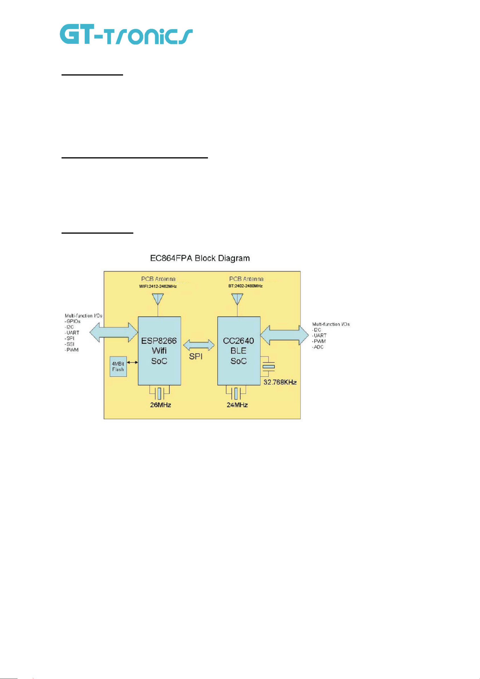
Block Diagram
RC and Interactive Toy
Wireless Alarm and Security Controller
Lighting and HAVC control
Remote Control and Assisted Living
DataExchanger (serial data transfer)
Page 2 of 9
Detail Descriptions
EC864FPA integrates Expressif’s ESP8266 Wifi SoC and Texas Instrument’s CC2640 BLE SoC to form an
integrated module to provide WLAN and BLE connectivity. Four dedicated I/Os from each SoC are connected together
for inter-chip communications (e.g. SPI).
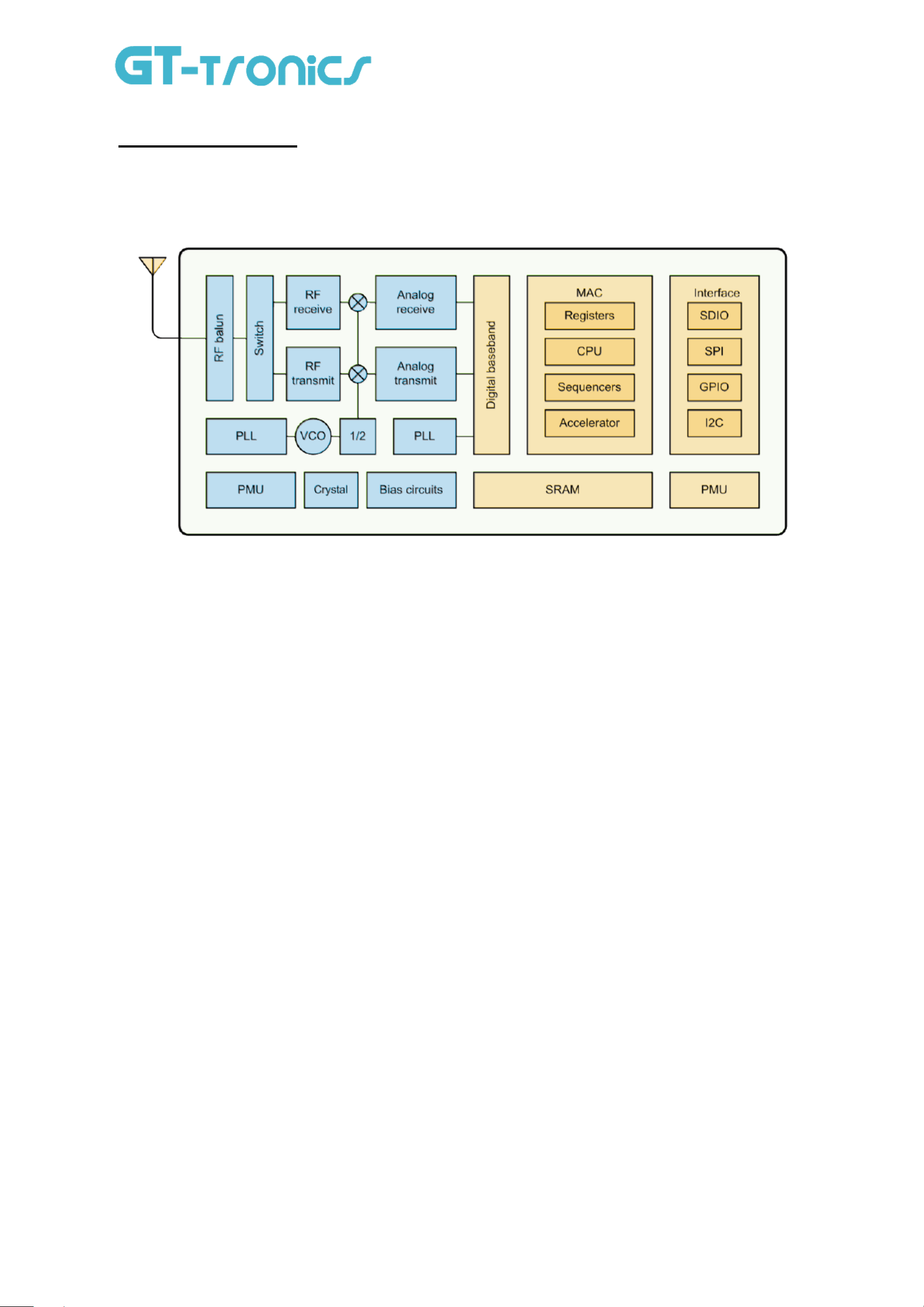
ESP8266 SoC
ESP8266EX offers a complete and self-contained Wi-Fi networking solution; it can be used to host the
application or to offload Wi-Fi networking functions from another application processor. When ESP8266EX hosts the
application, it boots up directly from an external flash. In has integrated cache to improve the performance of the system
in such applications. Alternately, serving as a Wi-Fi adapter, wireless internet access can be added to any
microcontroller -based design with simple connectivity (SPI/SDIO or I2C/UART interface). ESP8266EX is among the
most integrated WiFi chip in the industry; it integrates the antenna switches, RF balun, power amplifier, low noise
receive amplifier, filters, power management modules, it requires minimal external circuitry, and the entire solution,
including front-end module, is designed to occupy minimal PCB area. ESP8266EX also integrates an enhanced
version of Tensilica’s L106 Diamond series 32-bit processor, with on-chip SRAM, besides the Wi-Fi functionalities.
ESP8266EX is often integrated with external sensors and other application specific devices through its GPIOs; codes
for such applications are provided in examples in the SDK.
Sophisticated system-level features include fast sleep/wake context switching for energy-efficient VoIP, adaptive
radio biasing for low-power operation, advance signal processing, and spur cancellation and radio co-existence features
for common cellular, Bluetooth, DDR, LVDS, LCD interference mitigation. For more detail information on ESP8266,
please refer to ESP8266EX : A Beginner’s Guide.
Page 3 of 9

CC2640 SoC
CC2640 is a wireless MCU targeting Bluetooth Smart applications. The CC2640 device contains a 32-bit ARM
Cortex-M3 processor that runs at 48 MHz as the main processor and a rich peripheral feature set that includes a unique
ultralow power sensor controller. This sensor controller is ideal for interfacing external sensors and for collecting analog
and digital data autonomously while the rest of the system is in sleep mode. Thus, the CC2640 device is ideal for a wide
range of applications where long battery lifetime, small form factor, and ease of use is important.
The Bluetooth Low Energy controller is embedded into ROM and runs partly on an ARM Cortex-M0 processor.
This architecture improves overall system performance and power consumption and frees up flash memory for the
application. For more detail information on CC2640, please refer to CC2640 SimpleLink Bluetooth Smart Wireless MCU
(SWRS176A) from Texas Instruments.
Page 4 of 9

General Electrical Specification
Absolute Maximum Ratings
Ratings Min. Max.
Storage Temperature
Supply Voltage VDD
Recommended Operating Condition
Operating Condition Min. Max.
Operating Temperature range – (C-grade)
Supply Voltage VDD, VDDIO
-40 ℃ +90 ℃
-0.3 V 3.9 V
-20 ℃ +75 ℃
3.0 V 3.8 V
Page 5 of 9

Pins Configurations
EC864FPA
pin No. Pin Name Pin No. Pin Name
1 GND 21 GND
2 TOUT 22 BT_V33
3 WF_V33 23 DIO_4
4 CH_PD 24 DIO_3
5 MTMS 25 DIO_2
6 MTDI 26 DIO_0
7 MTCK 27 GND
8
9
10
11
12 GPIO4 32 DIO_6
13 XPD_DCD 33 BT_RSTB
14 GPIO5 34 GND
15 GND
16 WF_RSTB
17 URXD
18 UTXD
19 DIO_7
20 DIO 8
MTDO 28 GND
GND 29 JTAG_TSMC
GPIO2 30 JTAG_TCKC
GPIO0 31 DIO_5
Page 6 of 9

Module Outline
EC864FPA Module Outline
Page 7 of 9

Precautions
Storage Condition
This product should be stored without opening the packing, and under temperature 0-60 °C and humidity 30-70% RH. It
should be used within 15 months after reception.
ElectroStatic Discharge (ESD)
This product is sensitive to ElectroStatic Discharge (ESD). Observe precautions for handling electrostatic sensitive devices.
Such precautions are described in the ANSI/ESD S20.20, IEC/ST61340-5, JESD625-A or equivalent standards.
Module Reflow Installation
For RoHS/Pb-free applications, Sn96.5/Ag3.0/Cu0.5 solder is recommended.
Profile Feature Recommended Parameters
Ramp-up rate before liquidous < 2°C / second
Preheat 150-200°C 60-90 seconds
Maximum time at liquidous 40 – 80 seconds
Maximum peak temperature 230° - 240°C (below 250°C)
Ramp-down rate < 6°C / second
Ordering Information
Part Number FW Code Available Description
EC864FPA
Please check with
your sales rep
WiBlue module with integrated PCB antenna
Revision History
Rev. Date Description By
01 2015-09-02 Initial release Paul
02 2015-09-22 Updated Module Outline Paul
03 2016-06-29 Modified block diagram and added detail descriptions Paul
Page 8 of 9

Host Infor
This module was defined to be used for specific host only. The designated host for this module was:
Company: GT-tronics HK Ltd.
Address: B210, Tonic Industrial Center, 19 Lam Hing Street, Kowloon Bay, Hong Kong
Host Model Name: WiBlue_Breakout_Board_v02
Host brand name: GT-tronics
mation
FCC RF Exposure Requirement
1.At least 20cm separation distance between the antenna and the user’s body must be maintained at all times. And must not transmit
simultaneously with any other antenna or transmitter, except in accordance with FCC multi transmitter product procedures.
2.To comply with FCC regulations limiting both maximum RF output power and human exposure to RF radiation, the antenna
gain is
-0.30dBi for BLE; 2dBi for WIFI.
Please be noticed following information and instructions should be placed in the end-user’s
operating manual
The Module has been granted as full modular approval for mobile applications.
1. Separate approval is required for all other operating configurations, including portable configurations with respect to 2.1093 and
OEM is responsible for meeting SAR requirement of end product.
2. The Module and its antenna must not be co-located or operating in conjunction with any other transmitter or antenna within a host
device. This equipment complies with FCC RF radiation exposure limits set forth for an uncontrolled environment.
3. A label must be affixed to the outside of the end product into which the module is incorporated, with a statement similar to the
following: contains FCC ID:
4. The module shall be in non-detachable construction protection into the finished products, so that the end-user has to destroy the
module while remove or install it.
5.
A certified modular has the option to use a permanently affixed label, or an electronic label. For a permanently affixed label, the
module must be labeled . The OEM manual must provide clear instructions explaining to the OEM the labeling requirements,
options and OEM user manual instructions that are required.
For a host using this FCC certified modular with a standard fixed label, if (1) the module’s FCC ID is not visible when installed in
the host, or (2) if the host is marketed so that end users do not have straightforward commonly used methods for access to remove
the module so that the FCC ID of the module is visible.
B4OEC86XFPX
.
6.
Host product is required to comply with all applicable FCC equipment authorizations regulations, requirements and equipment
functions not associated with the transmitter module portion. Compliance must be demonstrated to regulations for other transmitter
components within the host product; to requirements for unintentional radiators (Part 15B). To ensure compliance with all
non-transmitter functions the host manufacturer is responsible for ensuring compliance with the module(s) installed and fully
operational. If a host was previously authorized as an unintentional radiator under the Declaration of Conformity procedure without
a transmitter certified module and a module is added, the host manufacturer is responsible for ensuring that the after the module is
installed and operational the host continues to be compliant with the Part 15B unintentional radiator requirements. Since this may
depends on the details of how the module is integrated with the host, we suggest the host device to recertify part 15B to ensure
complete compliance with FCC requirement: Part 2 Subpart J Equipment Authorization Procedures , KDB784748 D01 v07, and
KDB 997198 about importation of radio frequency devices into the United States.
Page 9 of 10

FCC Certification Requirement:
The end product with an embedded Module may
Part 15 unintentional emi
Note: This module is intended for use in
for separate approval to satisfy the SAR
This device complies with Part 15 of the FCC Rules.
Operation is subject to the following two conditions:
(1) this device may not cause harmful interference, and
(2) this device must accept any interference received, in
may cause undesired operation.
approved by GT-tronics HK Ltd. ma
ssion testing requirements and
a portable device, you are responsible
requirements of FCC Part 2.1093.
Changes or modifications made to this equipment not expressly
y void the FCC authorization to
also need to pass the FCC
be properly authorized per FCC Part 15.
cluding interference that
operate this equipment.
Page 10 of 10
 Loading...