

BC830RPAClass2 Bluetooth Module
Features
l Class 2 module with printed PCB antenna
l 64Kbit EEPROM
l Fully Qualified Bluetoothv4.0
l CSR BC8630ROMchip
l Low current consumption
l Supports 1.8v,3.3VI/Ooperations.
l SupportsLi-ion batterywith maximum 500mA charging current.
l High quality 95db SNR on DAC playback
l Supports USB audio
l Supportssingle/dual-mic input
l Interface: PIOs, UART, SPI(for programming)
l Built-in DSP Co-Processor for audio signal processing
l Supportsof noise and echo cancellation
l Configurable 5-band EQ
l 802.11 Co-existence
l A2DPandAVRCP profilessupport
l SBC,AAC,andMP3decoder support fordirect streaming
l Optional NFC pairing supports
l RoHS compliant
l Dimension:31.1x 12.0 x 2.2 mm
(1)
Notes :
(1) : HFP v1.6 profileissupported in BC835RPA
Applications
· High Quality Mono/Stereo Wireless Headsets
· Wireless Speakers
· Home-theater Sound Bar
· Bluetooth-Enabled Wireless Gateways
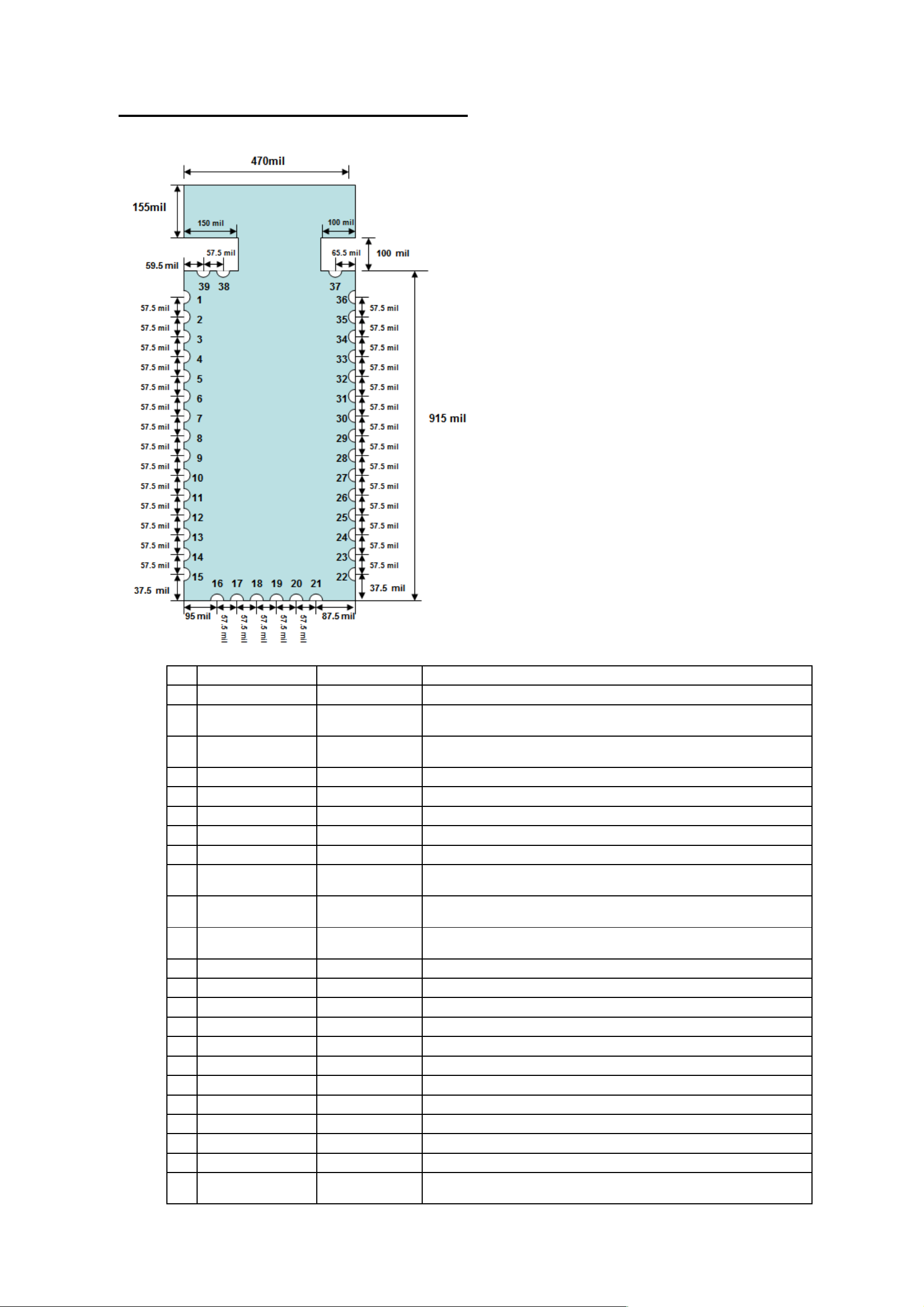
Module Outlineand Pin Assignments
PIN
NAME TYPE FUNCTION
1
GNDGNDGround
2
Line_in_LP/
Mic-AP
3
Line_in_LN/
Mic-AN
4
SPK_LNAnalog OutputLeft channel differential –ve audio output
5
SPK_LPAnalog OutputLeft channel differential +ve audio output
6
SPK_RPAnalog OutputRight channel differential –ve audio output
7
SPK_RPAnalog OutputRight channel differential +ve audio output
8
PIO13
9
VPADPower1.8v / 3.3v power supply for all PIOs, UART port, on module
10
Line_in_RP/
Mic-BP
11
Line_in_RN/
Mic-BN
12
GNDGNDGround
13
PIO17
Analog InputLeft channel +ve audio line in. (Also serves as Mic 1 +ve input in
BC835RPA)
Analog InputLeft channel-ve audio line in. (Also serves as Mic 1-ve input in
BC835RPA)
Bi-directional
Analog InputRight channel +ve audio line in. (Also serves as Mic 2 +ve input in
Analog InputRight channel-ve audio line in. (Also serves as Mic 2-ve input in
Bi-directional
Programmable Input/Output line.
EEPROM and SPI programming ports.
BC835RPA)
BC835RPA)
Programmable Input/Output line.
14
PIO18
15
PIO6
16
GNDGNDGround
17
UART_TXCMOS OutputUART port data transmit output
18
UART_RXCMOS InputUART port data receive output
19
SPI_PCMBCMOS InputSPI programming port enable (high active).
20
LED0Open DrainLED output
21
LED1Open DrainLED output
22GNDGNDGround
RESETBCMOS inputReset if low. Input debounced so must be low for >5ms to cause a
23
Bi-directional
Bi-directional
Programmable Input/Output line.
Programmable Input/Output line.
reset

SPI_CLK CMOS Input Serial Peripheral Interface Clock
24
SPI_MISO CMOS OutputSerial Peripheral Interface Data Output
25
SPI_MOSI CMOS Input Serial Peripheral Interface Data Input
26
SPI_CSB CMOS Input Chip Select For Synchronous Serial Interface active low
27
28V18_OUTPower Output1.8v output from module
29PIO21
30USB_DN
31USB_DP
32CHG-EXTAnalog OutputExternal charging control output.
33
VBAT_SENSEAnalog InputBattery level sensing input.
34VBATPower inputPower input.
35VCHGPower Input5V charging input.
36AGNDAnalog GroundAudio analog ground
37MIC_BiasAnalog OutputMic circuit bias control.
38AIO0Analog InputAuxiliaryADC input.
39VREGCMOS InputPower up control input.
Bi-directional
Bi-directional
Bi-directional
Programmable Input/Output line.
USB port D-
USB port D+

The above schematic shows a typical application ofBC830RPAmodulewith PIOs running at 1.8v.
Power supply
The whole module shall bepowered by a single cell 3.7v Li-ion rechargeable battery(VBAT, pin#34). A coupling
capacitorof 2.2uFshould be placed as close to this pin as possible.The module will output 1.8v at VPAD (pin #28).All
PIO pins, SPI programming port and UART port will runonthis power rail.
Differential Audio Outputs
The output stage digital circuitry converts the signal from 16-bit per sample, linear PCM of variable samplingfrequencyto
bit stream, which is fed into the analogue output circuitry.The output stage circuit comprises a DAC with gain setting and class AB
output stage amplifier. The output isavailable as a differential signal between SPK_LN and SPK_LP for the left channel, asthe
schematicshows,and between SPK_RN and SPK_RP for the right channel.The output stage is capable of driving a speaker directly
when its impedance isat least 8Ω.
UART Port
BC830RPAhas a standard UART serial interface that provides a simple mechanism forcommunicating with other serial
devices using the RS232 protocol.A typical application will beconnecting to an external HCI host.WhenBC830RPAisconnected
to another digital device, RX and TX transfer data between the 2 devices.UART configuration parameters, such as baud rate and
packet format, are setby configuration of theBC8630ROM chip.
To communicate with the UART at its maximum data rate usinga standard PC, an accelerated serial port adaptercard is required for
the PC.
Possible UART Settings
ParameterPossible values
Minimum1200 baud (≤2%Error)Baud rate
Maximum9600 baud (≤1%Error)
ParityNone, Odd or Even
Number of stop bits1 or 2
Bits per byte8
SPI Programming Port
The SPI is used to program and configure the ROM firmware insideBC8630chip.It isrequired in production. Ensure the4
SPI signals are brought out to either test points or a header.Note that these four signalswillrunonthe1.8v power rail.
LED Drivers
BC830RPAincludes 2 pads dedicated to driving LED indicators. Both terminals can be controlledby firmware, The
terminals are open-drain outputs, so the LED must be connected from a positive supply rail to the pad in serieswith a current
limiting resistor.It is recommendedthat the LED pad, LED[0] or LED[1] pins, operate with a pad voltage below 0.5V. In thiscase,
the pad is like a resistor, RON.The resistance together with the external series resistor sets the currentin theLED.
Buttons
The example application has assigned the following functions to each PIO pins:
PIN
NAME
13
PIO17REVSelect previous song, fast rewind.
FunctionDescriptions
29PIO18FWDSelect next song, fast forward
14PIO21PLAY_PAUSEPlay / pause toggle
18PIO6VOL-Volumedecrease
15PIO13VOL+Volume increase
39VREGVREG_ENPoweron, sleep mode
Battery and Charging
The whole circuit is running with single cell 3.7v Li-ion battery connecting to the VBAT terminal. VBAT_SENSE is
shorted to this terminal for battery level detection. 5V charging input coming from the micro USB port is connected to the VCHG
terminal. In typicalheadset application, a maximum of 150mA charging current can be supportedwith internal charging.However,
external components can be added to boost the charging current to 500mA if needed.Note that a decoupling capacitor of 2.2uF
should be connected to VCHG.
Host Information
This device complies with part 15 of the FCC Rules. Operation is subject to the following two conditions: (1) This device may not cause harmful interference, and (2) this device
must accept any interference received, including interference that may cause undesired operation.
Changes or modifications not expressly approved by the party responsible for compliance could void the user's authority to operate the equipment.
NOTE: This equipment has been tested and found to comply with the limits for a Class B digital device, pursuant to Part 15 of the FCC Rules. These limits are designed to
provide reasonable protection against harmful interference in a residential installation. This equipment generates, uses and can radiate radio frequency energy and, if not
installed and used in accordance with the instructions, may cause harmful interference to radio communications. However, there is no guarantee that interference will not occur
in a particular installation. If this equipment does cause harmful interference to radio or television reception, which can be determined by turning the equipment off and on, the
user is encouraged to try to correct the interference by one or more of the following
measures:
-- Reorient or relocate the receiving antenna.
-- Increase the separation between the equipment and receiver.
-- Connect the equipment into an outlet on a circuit different from that to which the receiver is connected.
-- Consult the dealer or an experienced radio/TV technician for help.
FCC Radiation Exposure Statement
This modular complies with FCC RF radiation exposure limits set forth for an uncontrolled environment. This transmitter must not be co-located or operating in conjunction with
any other antenna or transmitter.
If the FCC identification number is not visible when the module is installed inside another device, then the outside of the device into which the module is installed must also
display a label referring to the enclosed module. This exterior label can use wording such as the following: Contains Transmitter Module FCC ID: B4OBC86XRPX or
Contains FCC ID: B4OBC86XRPX
when the module is installed inside another device, the user manual of this device must contain below warning statements;
1. This device complies with Part 15 of the FCC Rules. Operation is subject to the following two conditions:
(1) This device may not cause harmful interference.
(2) This device must accept any interference received, including interference that may cause undesired operation.
2. Changes or modifications not expressly approved by the party responsible for compliance could void the user's authority to operate the equipment.
The devices must be installed and used in strict accordance with the manufacturer's instructions as described in the user documentation that comes with the product.
This module was defined to be used for specific host only. The designated host for this module was:
Company: GT-tronics HK Ltd.
Address: B202, Tonic Industrial Center, 19 Lam Hing Street, Kowloon Bay, HongKong
Host Model Name:Bluetooth Audio Receiver
Host brand name:N/A
FCC RF Exposure Requirement
1. At least 20cm separation distance between the antenna and the user’s body must be maintained at all times. And must nottransmit
simultaneously with any other antenna or transmitter, except in accordance with FCC multi transmitter productprocedures.
2. To comply with FCC regulations limiting both maximum RF output power and human exposure to RF radiation, the maximum
antenna gain including cable loss in amobile-only exposure condition must not exceed 0dBi in the 2.4G band.
3. A user manual with the end product must clearly indicate the operating requirements and conditions that must be observed to
ensure compliance with current FCC RF exposure guidelines.
Please be noticed following information and instructions should be placed in the end-user’s
operating manual
The Module has been granted as limited modular approval for mobile applications. This Module must be installed in the designated
host as specified in this manual.
1. Separate approval is required for all other operating configurations, including portable configurations with respect to 2.1093 and
different antenna configurations.
2. The Module and its antenna must not be co-located or operating in conjunction with any other transmitter or antenna within ahost
device. This equipment complies with FCC RF radiation exposure limits set forth for an uncontrolled environment.
3. A label must be affixed to the outside of the end product into which themodule is incorporated, with a statement similar to the
following: ForBC830RPA: This device contains FCC ID:B4OBC86XRPX.
4. The module shall be in non-detachable construction protection into the finished products, so that the end-user has to destroy the
module while remove or install it.
5. This module is to be installed only in mobile or fixed applications. According to FCC part 2.1091(b) definition of mobile and
fixed devices is:.
Mobile device:
A mobile device is defined as a transmitting device designed to be used in other than fixed locations and to generally be used in such
a way that a separation distance of at least 20 centimeters is normally maintained between the transmitter’s radiating structure(s) and
the body of the user or nearby persons. In this context,the term ‘‘fixed location’’ means that the device is physically secured at one
location and is not able to be easily moved to another location.
Portable device:
For purposes of this section, a portable device is defined as a transmittingdevice designed to be used so that the radiating structure(s)
of the device is/are within 20 centimeters of the body of the user.
6. Separate approval is required for all other operating configurations, including portable configurations with respect to FCC Part
2.1093 and different antenna configurations.
7. A certified modular has the option to use a permanently affixed label, or an electronic label. For a permanently affixed label, the
module must belabeledwith an FCC ID:B4OBC86XRPX. The OEM manualmust provide clear instructions explaining to the
OEM thelabelingrequirements, options and OEM user manual instructions that are required.
For a host usingthis FCC certified modular with a standard fixed label, if (1) the module’s FCC ID is notvisiblewhen installed in
the host, or (2) if the host is marketed so that end users do not havestraightforward commonly used methods for access to remove
the module so that the FCC ID ofthe module is visible; then an additional permanent label referring to theenclosed module:
“Contains Transmitter Module FCC ID:B4OBC86XRPX” or “Contains FCC ID:B4OBC86XRPX” mustbe used. The host OEM
user manual must also contain clear instructions on how end users canfind and/or access the module and the FCC ID.
8. Host product is required to comply with all applicable FCC equipment authorizations regulations, requirements and equipment
functions not associated with the transmitter module portion.Compliancemust be demonstrated to regulations for other transmitter
components within the host product; to requirements for unintentional radiators (Part 15B). To ensure compliance with all
non-transmitter functions the host manufacturer is responsible for ensuring compliance with the module(s) installed and fully
operational. Ifa host was previously authorized as an unintentional radiator under the Declaration of Conformity procedure without
a transmitter certified module and a module is added, the host manufacturer is responsible for ensuring that the after the module is
installed and operational the host continues to be compliant with the Part 15B unintentional radiator requirements. Since this may
dependson the details of how the module is integrated with the host, we suggest the host device to recertify part 15B to ensure
complete compliance with FCC requirement: Part 2 Subpart J Equipment Authorization Procedures , KDB784748 D01 v07, and
KDB 997198 about importation of radio frequency devices into the United States.
 Loading...