

BC865RPA Class 2 Bluetooth Module
Features
Class 2 module with printed PCB antenna
64Kbit EEPROM
Fully Qualified Bluetooth v4.0
CSR BC8645 ROM chip
Low current consumption
Supports 1.8v, 3.3V I/O operations.
Supports Li-ion battery with maximum 500mA charging current.
High quality 95db SNR on DAC playback
Supports USB audio
Supports single/dual-mic input
Interface: PIOs, UART, SPI (for programming)
Built-in DSP Co-Processor for audio signal processing
Supports of noise and echo cancellation
Configurable 5-band EQ
802.11 Co-existence
A2DP, AVRCP, HSP, HFP profile support
SBC, AAC, MP3 and aptX decoder support for direct streaming
Optional NFC pairing support
RoHS compliant
Dimension: 31.1 x 12.0 x 2.2 mm
Applications
• High Quality Mono/Stereo Wireless Headsets
• Hands-Free Car Kits
• Wireless Speakers
• Home-theater Sound Bar
• Bluetooth-Enabled Wireless Gateways
This module is limited to OEM Installation only.
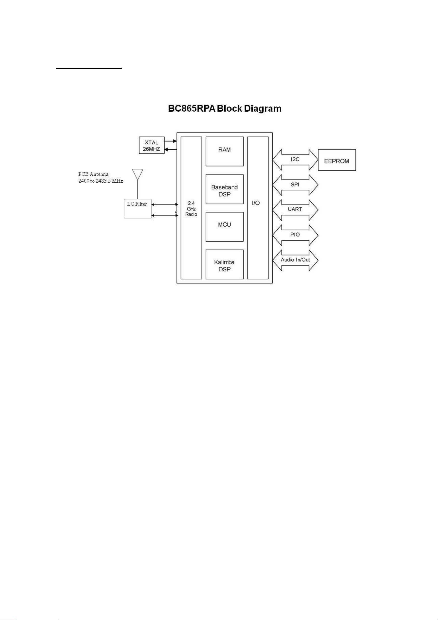
Block Diagram
BC865RPA is a Class 2 Bluetooth sub-system using BC8645 ROM chipset from leading Bluetooth chipset supplier
Cambridge Silicon Radio. .It interfaces to a 64Kbit serial EEPROM. The software stack running on the BC8645 ROM chipset is
fully compliant to Bluetooth Specification v4.0. BC865RPA also has necessary matching filters to interface with a build-in PCB
antenna, which forms a very cost effective radio subsystem.

Applications Example

The above schematic shows a typical application of BC865RPA module with PIOs running at 1.8v. Double click
on the diagram to see the detail drawings.
Power supply
The whole module shall be powered by a single cell 3.7v Li-ion rechargeable battery (VBAT, pin#34). A coupling
capacitor of 2.2uF should be placed as close to this pin as possible. The module will output 1.8v at VPAD (pin #9). All
PIO pins, SPI programming port and UART port will run at this power rail.
Differential Audio Outputs
The output stage digital circuitry converts the signal from 16-bit per sample, linear PCM of variable sampling frequency to
bit stream, which is fed into the analogue output circuitry. The output stage circuit comprises a DAC with gain setting and class AB
output stage amplifier. The output is available as a differential signal between SPK_LN and SPK_LP for the left channel, as the
schematic shows, and between SPK_RN and SPK_RP for the right channel. The output stage is capable of driving a speaker directly
when its impedance is at least 8Ω.
UART Port
BC865RPA has a standard UART serial interface that provides a simple mechanism for communicating with other serial
devices using the RS232 protocol. A typical application will be connecting to an external HCI host. When BC865RPA is connected
to another digital device, RX and TX transfer data between the 2 devices. UART configuration parameters, such as baud rate and
packet format, are set by configuration of the BC8645 ROM chip.
To communicate with the UART at its maximum data rate using a standard PC, an accelerated serial port adapter card is required for
the PC.
Possible UART Settings
Parameter Possible values
Minimum 1200 baud (≤2%Error) Baud rate
Maximum 9600 baud (≤1%Error)
Parity None, Odd or Even
Number of stop bits 1 or 2
Bits per byte 8
SPI Programming Port
The SPI is used to program and configure the ROM firmware inside BC8645 chip. It is required in production. Ensure the 4
SPI signals are brought out to either test points or a header. Note that these four signals will run at 1.8v power rail.
Mic Inputs
The microphone bias, MIC_BIAS, provides power to external mic circuitry, and is configurable from 1.8v to 2.4v. The
MIC_BIAS is like any voltage regulator and requires a minimum load to maintain regulation. The MIC_BIAS maintains regulation
within the limits 0.200mA to 1.230mA. The input impedance at MIC_A_N, MIC_A_P, MIC_B_N and MIC_B_P is typically
6.0kΩ
.
LED Drivers
BC865RPA includes 2 pads dedicated to driving LED indicators. Both terminals can be controlled by firmware, The
terminals are open-drain outputs, so the LED must be connected from a positive supply rail to the pad in series with a current
limiting resistor. It is recommended that the LED pad, LED[0] or LED[1] pins, operate with a pad voltage below 0.5V. In this case,
the pad is like a resistor, RON . The resistance together with the external series resistor sets the current in the LED.
Buttons
The example application has assigned the following functions to each PIO pins:
PIN
NAME
Function Descriptions
13
PIO17 REV Select previous song, fast rewind.
PIO21
29
FWD Select next song, fast forward
14 PIO18 PLAY_PAUSE Play / pause toggle
PIO20
18
PIO19
15
VBAT_SENSE
33
VOL- Volume decrease
VOL+ Volume decrease
BAT_SENSE Battery level detection
39 VREG VREG_EN Power on, sleep mode

Battery and Charging
The whole circuit is running with single cell 3.7v Li-ion battery connecting to the VBAT terminal. VBAT_SENSE is
shorted to this terminal for battery level detection. 5V charging input coming from the micro USB port is connected to the VCHG
terminal. In this typical circuit, a maximum of 150mA charging current can be supported. Note that a decoupling capacitor of
2.2uF should be connected to VCHG.
Host Information
This module was defined to be used for specific host only. The designated host for this module was:
Company: GT-tronics HK Ltd.
Address: B202, Tonic Industrial Center, 19 Lam Hing Street, Kowloon Bay, Hong Kong
Host Model Name: BTSPK
Host brand name: GT-tronics
FCC RF Exposure Requirement
1. At least 20cm separation distance between the antenna and the user’s body must be maintained at all times. And must not
transmit simultaneously with any other antenna or transmitter, except in accordance with FCC multi transmitter product
procedures.
2. To comply with FCC regulations limiting both maximum RF output power and human exposure to RF radiation, the maximum
antenna gain including cable loss in a mobile-only exposure condition must not exceed 0dBi in the 2.4G band.
3. A user manual with the end product must clearly indicate the operating requirements and conditions that must be observed to
ensure compliance with current FCC RF exposure guidelines.
Please be noticed following information and instructions should be placed in the end-user’s
operating manual
The Module has been granted as limited modular approval for mobile applications. This Module must be installed in the designated
host as specified in this manual.
1.
Separate approval is required for all other operating configurations, including portable configurations with respect to 2.1093 and
different antenna configurations.
2. The Module and its antenna must not be co-located or operating in conjunction with any other transmitter or antenna within a
host device. This equipment complies with FCC RF radiation exposure limits set forth for an uncontrolled environment.
3. A label must be affixed to the outside of the end product into which the module is incorporated, with a statement similar to the
following: For BC865RPA: This device contains FCC ID: B4OBC86XRPA.
4. The module shall be in non-detachable construction protection into the finished products, so that the end-user has to destroy the
module while remove or install it.
5. This module is to be installed only in mobile or fixed applications. According to FCC part 2.1091(b) definition of mobile and
fixed devices is:.
Mobile device:
A mobile device is defined as a transmitting device designed to be used in other than fixed locations and to generally be used in such
a way that a separation distance of at least 20 centimeters is normally maintained between the transmitter’s radiating structure(s) and
the body of the user or nearby persons. In this context, the term ‘‘fixed location’’ means that the device is physically secured at one
location and is not able to be easily moved to another location.
Portable device:
For purposes of this section, a portable device is defined as a transmitting device designed to be used so that the radiating
structure(s)
of the device is/are within 20 centimeters of the body of the user.
6. Separate approval is required for all other operating configurations, including portable configurations with respect to FCC Part
2.1093 and different antenna configurations.
7. A certified modular has the option to use a permanently affixed label, or an electronic label. For a permanently affixed label, the
module must be labelled with an FCC ID: B4OBC86XRPA. The OEM manual must provide clear instructions explaining to the
OEM the labelling requirements, options and OEM user manual instructions that are required
For a host using a this FCC certified modular with a standard fixed label, if (1) the module’s FCC ID is not
visible when installed in the host, or (2) if the host is marketed so that end users do not have
straightforward commonly used methods for access to remove the module so that the FCC ID of
the module is visible; then an additional permanent label referring to the enclosed module:
“Contains Transmitter Module FCC ID: B4OBC86XRPA” or “Contains FCC ID: B4OBC86XRPA” must
be used. The host OEM user manual must also contain clear instructions on how end users can
find and/or access the module and the FCC ID.
8. Host product is required to comply with all applicable FCC equipment authorizations regulations, requirements and equipment
functions not associated with the transmitter module portion. compliance must be demonstrated to regulations for other transmitter
components within the host product; to requirements for unintentional radiators (Part 15B). To ensure compliance with all
non-transmitter functions the host manufacturer is responsible for ensuring compliance with the module(s) installed and fully
operational. If a host was previously authorized as an unintentional radiator under the Declaration of Conformity procedure without
a transmitter certified module and a module is added, the host manufacturer is responsible for ensuring that the after the module is
installed and operational the host continues to be compliant with the Part 15B unintentional radiator requirements. Since this may

depend on the details of how the module is integrated with the host, we suggest the host device to recertify part 15B to ensure
complete compliance with FCC requirement: Part 2 Subpart J Equipment Authorization Procedures , KDB784748 D01 v07, and
KDB 997198 about importation of radio frequency devices into the United States.
FCC Certification Requirement:
The end product with an embedded Module may also need to pass the FCC Part 15 unintentional emission testing requirements and
be properly authorized per FCC Part 15.
Note: If this module is intended for use in a portable device, you are responsible for separate approval to satisfy the SAR
requirements of FCC Part 2.1093.
This device complies with Part 15 of the FCC Rules.
Operation is subject to the following two conditions:
(1) this device may not cause harmful interference, and
(2) this device must accept any interference received, including interference that may cause undesired operation.
Changes or modifications made to this equipment not expressly approved by GT-tronics HK Ltd. may void the FCC authorization to
operate this equipment.
**** END ****
 Loading...