

GTT Opticom GPS System Installation Manual

Installation Manual October 2009
™
Opticom
Intersection Equipment
GPS System

Intersection Equipment Installation Instructions i
Table of Contents
1 About This Manual ........................................................................................................................................... 1
1.1 Purpose of Manual ........................................................................................................................ 1
1.2 Manual Conventions ..................................................................................................................... 1
1.3 Related Publications ..................................................................................................................... 1
1.4 Manual Organization .................................................................................................................... 1
2 Safety Information ............................................................................................................................................ 2
2.1 Intended Use ................................................................................................................................ 2
2.2 Technical Support ......................................................................................................................... 2
2.3 Safety Messages and Safety Labels ................................................................................................ 2
2.3.1 Safety Message Format ....................................................................................................................... 2
2.3.2 Safety Label Format ............................................................................................................................. 3
2.4 Safety Messages Contained in this Manual .................................................................................... 4
2.5 Label Locations ............................................................................................................................. 6
2.6 Safety Considerations .................................................................................................................... 8
2.6.1 Personal Safety Equipment and Clothing .......................................................................................... 8
2.6.2 Work Zone Traffic Control ................................................................................................................. 8
2.6.3 Electric Shock ...................................................................................................................................... 8
2.7 Disposal of Device ....................................................................................................................... 8
2.8 FCC Statement .............................................................................................................................. 8
3 Description ......................................................................................................................................................... 9
3.1 Intersection Equipment ............................................................................................................... 10
4 Features ............................................................................................................................................................ 12
5 Installation ....................................................................................................................................................... 13
5.1 Model 1010 Radio/GPS unit mounting Location Considerations ................................................. 13
5.2 Model 1010 Radio/GPS Unit Installation .................................................................................... 17
5.3 Model 1012 Radio Installation .................................................................................................... 20
5.3.1 Model 1050 Antenna mounting ...................................................................................................... 20
5.3.2 Radio mounting ................................................................................................................................. 21
5.3.2.1 Radio/GPS Unit Cable Terminations ....................................................................................... 22
5.4 System Configurations ................................................................................................................ 24
5.4.1 Type 170 Controller Installations .................................................................................................... 24
5.4.2 NEMA Controller Installations ......................................................................................................... 24
5.5 Installation — Type 170 Controllers ............................................................................................ 24
5.5.1 Phase Selector Installation ............................................................................................................... 24
5.5.2 Radio/GPS Cable Connection .......................................................................................................... 26
5.5.3 Auxiliary Interface Panel Installation .............................................................................................. 27
5.5.4 Green Sense Wiring with Auxiliary Interface Panel ..................................................................... 29
5.5.4.1 Additional Output Connections ............................................................................................... 30
5.5.4.2 Turn Signal Dependant Operation Example ........................................................................... 31
5.5.5 Alternate Green Sense Wiring with Model 1035Auxiliary Harness ............................................ 32
5.5.5.1 Changing Where Wires Exit Connector Housing ................................................................... 34
5.5.6 Communication Cable Installation.................................................................................................. 35
5.6 Installation — NEMA Controllers ................................................................................................ 36
5.6.1 Card Rack Installation ....................................................................................................................... 36
5.6.2 Phase Selector Installation ............................................................................................................... 38
Radio/GPS Cable Connection ........................................................................................................................ 39
5.6.3 Auxiliary Interface Panel Installation .............................................................................................. 39
5.6.4 Green Sense Wiring .......................................................................................................................... 39
5.6.5 Communication Cable Installation.................................................................................................. 39
5.7 Phase Selector Pin Index ............................................................................................................. 40

ii Intersection Equipment Installation Instructions
6 Communication Networks .............................................................................................................................. 43
6.1 TIA/RS-232 Communication Port ................................................................................................ 43
6.2 Rear Edge Communication Port .................................................................................................. 43
7 Phase Selector Setup ....................................................................................................................................... 44
7.1 Indicators .................................................................................................................................... 44
7.2 Switches ..................................................................................................................................... 45
8 Checkout .......................................................................................................................................................... 47
9 Troubleshooting............................................................................................................................................... 47
9.1 Fuse Location ............................................................................................................................. 47
9.2 Troubleshooting .......................................................................................................................... 48
10 Maintenance ................................................................................................................................................. 53
11 Appendix A: Card Rack Wiring Diagram ............................................................................................... 54
12 Appendix B: Opticom™ GPS System Output Connection Worksheet (High Priority only) .............. 55
13 Appendix B1: Opticom GPS Output Connection Worksheet (High & Low Priority) ......................... 56
14 Appendix C: Driving a Relay From a Phase Selector ............................................................................. 57
15 Appendix D Gate opener Card Rack ......................................................................................................... 59
15.1 Model 1045 Card Rack Installation ............................................................................................. 59
15.2 Relay Outputs ............................................................................................................................. 60

Intersection Equipment Installation Instructions 1
1 About This Manual
1.1 Purpose of Manual
Section 3. Description
Briefly describes the intersection equipment.
This manual provides step-by-step instructions for
installing and setting up the Global Traffic
Technologies Opticom™ GPS System*
intersection equipment. It is intended for use by
installers, maintenance personnel, and others who
are responsible for the installation and
maintenance of the system.
1.2 Manual Conventions
The conventions listed in Table 1-1 help to
make this manual easier to use by presenting a
uniform approach to the descriptions, phrases,
and nomenclature.
1.3 Related Publications
Opticom GPS System Vehicle Equipment
Installation Instructions.
Opticom GPS System Operation Manual.
1.4 Manual Organization
This manual is divided into ten sections and three
appendixes.
Section 4. Features
Describes important features and characteristics
of the intersection equipment.
Section 5. Installation
Contains step-by-step installation instructions.
Section 6. Communication Networks
Contains information about serial
communication.
Section 7. Phase Selector Setup
Describes the indicators and switches on the front
panel of the phase selector.
Section 8. Checkout
Contains information on how to check out and
test the installed system.
Section 9. Troubleshooting
Contains tests and problem solutions to
troubleshoot the installed system.
Section 10. Maintenance
Contains information and recommendations to
ensure reliable system operation.
Section 1. About This Manual
Contains information about the organization
and content of this manual.
Section 2. Safety Information
Contains important information about the safety
messages, safety labels, safety precautions, and
procedures for installation of this device.
Table 1-1. Manual Conventions
Element Convention Example
Abbreviations Lowercase
…except where
standard usage is uppercase
Names First or formal reference: initial
caps
Subsequent use or informal
reference: lowercase
*The method of using the components of the Opticom GPS system may be covered by one or more of US Patent
Numbers 5539398, 5926113, 5986575, 6243026.
Appendix A. Card Rack Wiring Diagram
Contains a wiring diagram of the card rack.
Appendix B. Opticom GPS System Output
Connection Worksheet
Contains a worksheet to record connections
between the phase selector and the traffic
controller for a particular intersection.
Appendix C. Driving a Relay
Contains information about driving a relay from a
phase selector output.
ms (milliseconds)
Mb (megabits)
MB (megabytes)
dB (decibel)
Opticom™ GPS System Intersection
Radio/GPS Unit
radio/GPS unit
2 Intersection Equipment Installation Instructions
2 Safety Information
We provide important safety information and
warnings to assist you in understanding and
avoiding potential harm to yourself, and possible
damage to equipment, during the installation of
the Opticom™ GPS System equipment. Although
we have included many potential hazards you
may encounter during the installation of this
equipment, we cannot predict all of the possible
hazards and this list should not be a substitute for
your judgment and experience.
Please read, understand, and follow all safety
information contained in these instructions
before installing the system equipment. Save
this installation manual and keep it near the
equipment.
If you are unsure about any part of this installation
or of the potential hazards discussed, please
contact your supervisor immediately.
2.1 Intended Use
The system is intended to assist authorized priority
vehicles through signalized intersections by
providing temporary right-of-way through vehicle
operator interface to the system and through the
use of common traffic controller functions. GTT
has not evaluated this product for use in any other
application.
2.2 Technical Support
If you have questions about the system, its use,
or operation, please contact your dealer or call
the GTT Technical Service department at 1800-258-4610.
2.3.1 Safety Message Format
Safety messages are designed to alert you to
potential hazards that can cause personal injury
to you or others. They can also indicate the
possibility of property damage.
Each safety message box contains a safety alert
symbol (
WARNING, CAUTION, or IMPORTANT NOTE;
and a safety message.
The signal words and symbols, and their
meanings, are shown below:
); one of three signal words:
WARNING
The safety message is in this box.
WARNING indicates a potentially hazardous
situation, which, if not avoided, could result in
death or serious injury.
CAUTION
The safety message is in this box.
CAUTION indicates a potentially hazardous
situation, which, if not avoided, may result in
minor or moderate injury.
IMPORTANT NOTE
The safety message is in this box.
2.3 Safety Messages and Safety Labels
We include safety messages and labels in this
manual to help you protect your safety and the
safety of others. This section contains important
information to help you recognize and understand
these safety messages.
Please read these messages before proceeding
with the installation.
IMPORTANT NOTE indicates a potentially
hazardous situation, which, if not avoided, may
result in property damage.
In addition to the symbols and words explained
above, each safety message identifies the hazard,
describes what you can and should do to avoid
the risk of exposure to the hazard, and tells the
probable consequences of not avoiding the
hazard.

Intersection Equipment Installation Instructions 3
2.3.2 Safety Label Format
We include safety labels on the devices to help
you protect your safety and the safety of others.
Safety labels are designed to alert you to potential
hazards associated with a piece of equipment that
can cause personal injury to you or others. They
can also indicate the possibility of property
damage.
Please read all safety labels.
Each safety label contains a safety alert symbol (
), one of two signal words: WARNING or
CAUTION, a pictorial showing the nature of the
hazard, and a safety message.
The signal words and symbols, and their
meanings, are shown below:
CAUTION indicates a potentially hazardous
situation, which, if not avoided, may result in
minor or moderate injury.
We consider safety labels to be an important part
of all devices and they should be replaced
immediately if they become hard to read.
If any of the safety labels are missing or cannot be
read, please contact your dealer or GTT Repair
department for a replacement.
WARNING indicates a potentially hazardous
situation, which, if not avoided, could result in
death or serious injury.
4 Intersection Equipment Installation Instructions
2.4 Safety Messages Contained in this
Manual
The following safety messages appear in this
manual:
WARNING
This equipment has been approved for mobile
applications where the equipment should be
used at distances greater than 20 cm from the
human body (with the exception of hands,
wrists, feet and ankles). Operation at distances
less than 20 cm is strictly prohibited.
NOTE: This equipment has been tested and
found to comply with the limits for a Class A
digital device, pursuant to part 15 of the FCC
Rules. These limits are designed to provide
reasonable protection against harmful
interference when the equipment is operated in
a commercial environment. This equipment
generates, uses, and can radiate radio frequency
energy and, if not installed and used in
accordance with the instruction manual, may
cause harmful interference to radio
communications. Operation of this equipment
in a residential area is likely to cause harmful
interference in which case the user will be
required to correct the interference at his own
expense.
REMARQUE IMPORTANTE
La modification du système radio/GPS risque
d’endommager sérieusement le matériel et d’annuler
la garantie. Ne pas tenter de modifier les circuits du
système radio/GPS de quelque façon que ce soit. En
modifiant le système radio et/ou l’antenne de quelque
façon que ce soit, la radio risque de ne plus répondre
aux exigences de la FCC/IC.
WARNING
Improper or incomplete programming of the
traffic controller may cause improper operation
of the traffic signals, which may result in
accidents and/or injuries. To avoid this
problem, verify that the operation of the traffic
controller is appropriate for your needs before,
during, and after actuation of the priority
control inputs. Improper operation of the
traffic signals may result in unsafe driver action.
NOTICE
This Class A digital apparatus complies
with Canadian ICES-003.
Cet appareil numérique de la classe A
conforme à la norme NMB-003 du
Canada.
IMPORTANT NOTE
Modifying the radio/GPS unit may seriously
damage the equipment and void the warranty.
Do not attempt to modify the radio/GPS
circuitry in any way. Modifying the radio and/or
antenna in any way may cause the radio to
violate FCC/IC requirements.
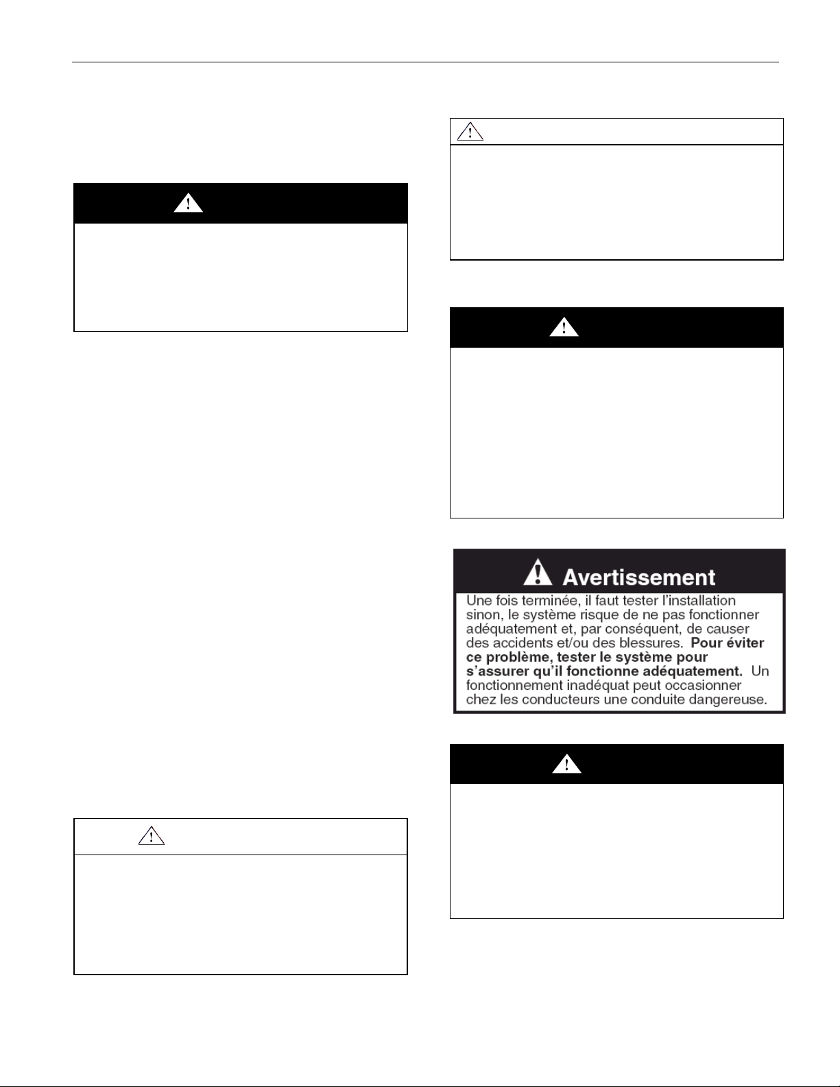
WARNING
This procedure may expose you to AC voltage
and the risk of electric shock or electrocution.
Turn off the AC mains and use accepted and
recognized safety precautions to avoid
exposure to the risk of electric shock or
electrocution. Electric shock may cause severe
injury or death.
Intersection Equipment Installation Instructions 5
WARNING
A completed installation that is not tested may
result in improper system operation, which
may result in accidents and/or injuries. To
avoid this problem, test the system to verify
proper operation. Improper system operation
may result in unsafe driver action.
6 Intersection Equipment Installation Instructions
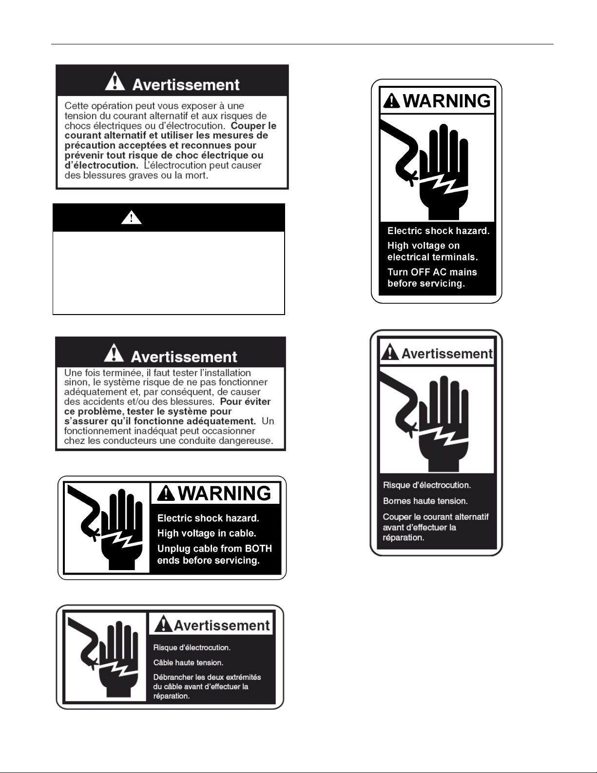
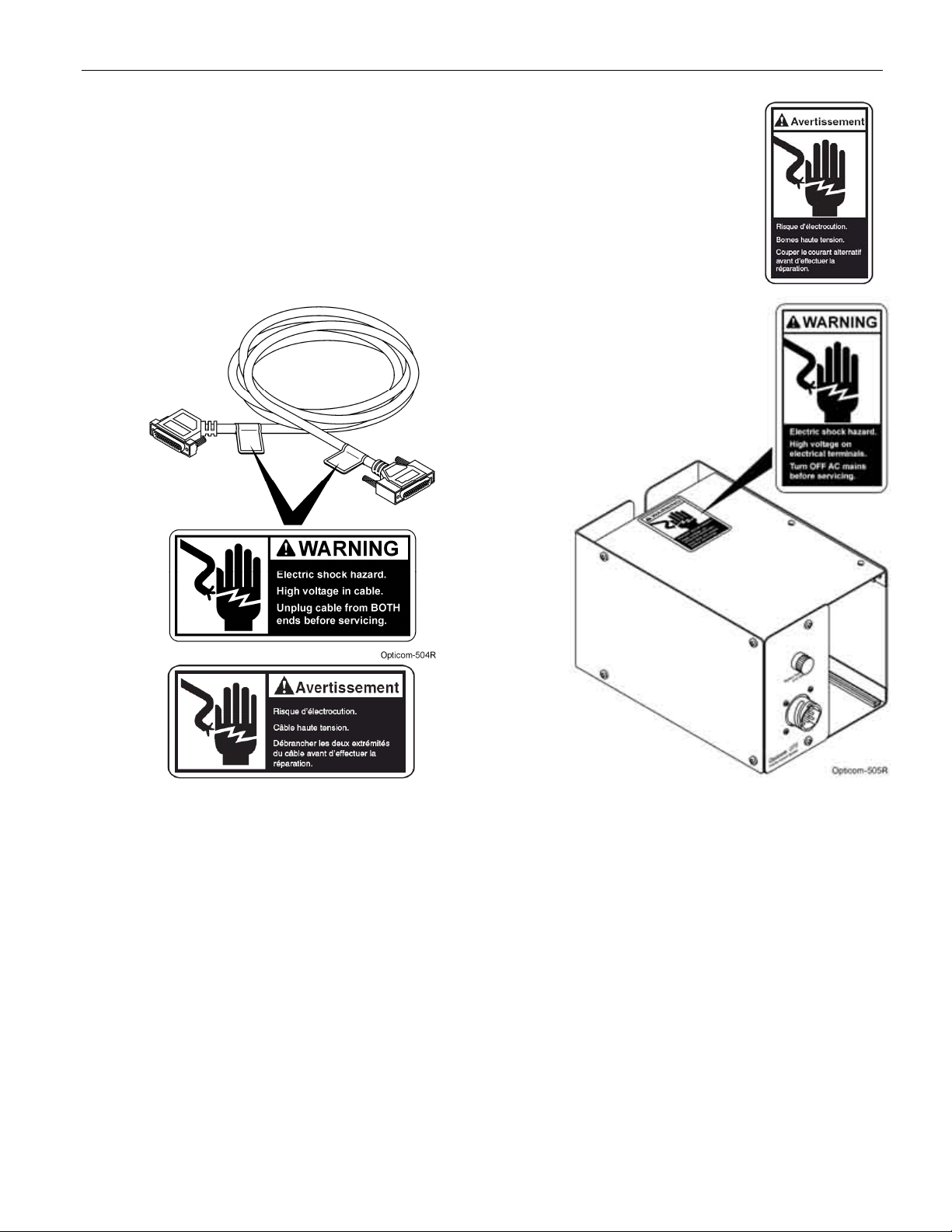
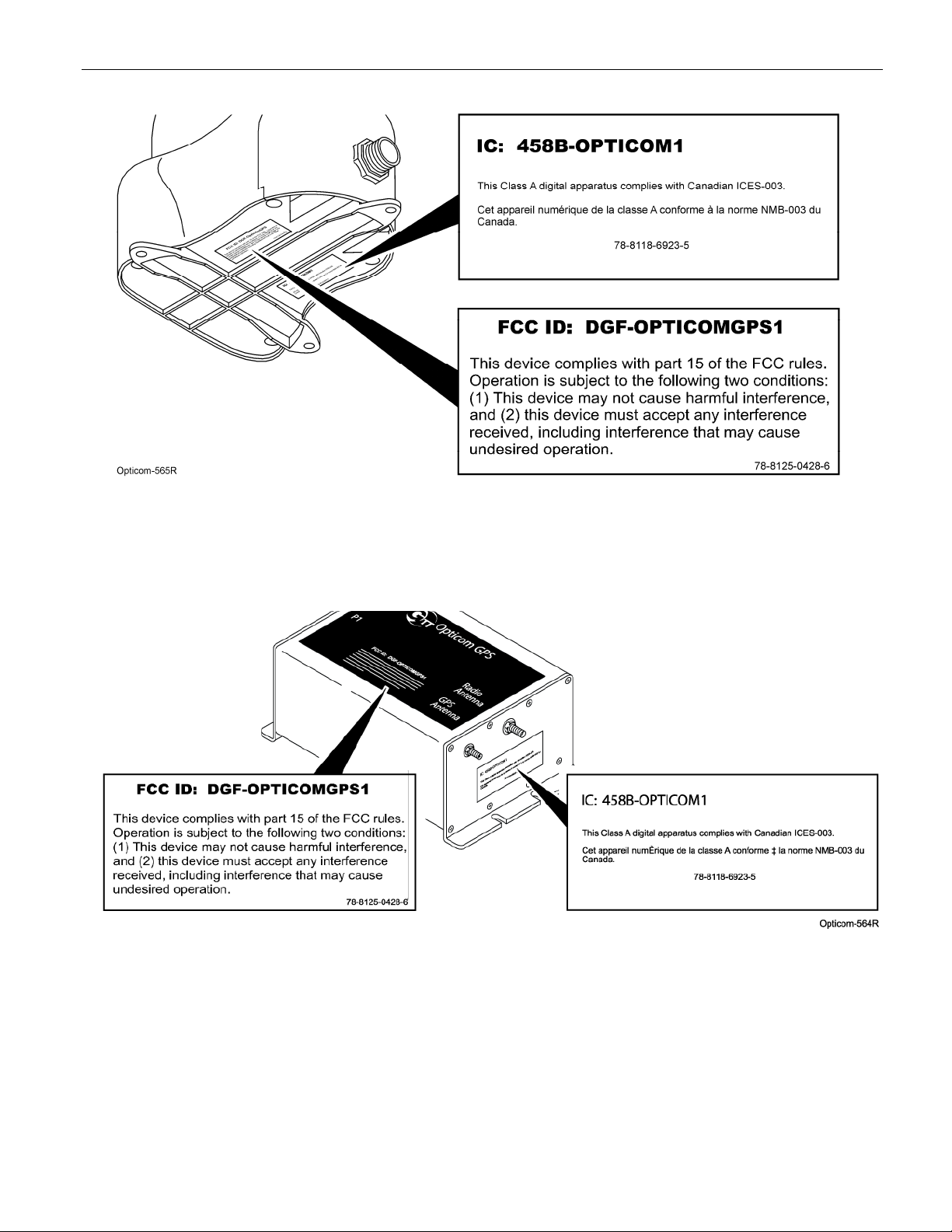
2.5 Label Locations
There are two safety labels, one FCC label and
one IC label on the Opticom™ GPS System
intersection equipment. If a label is missing or
cannot be read, please contact your dealer or the
GTT Repair department for a replacement. See
Figures 2-1, 2-2, and 2-3 for label locations.
Figure 2-1. Auxiliary Interface Panel Cable
Safety Label Location
Figure 2-2. Card Rack AC Terminal
Safety Label Location
Intersection Equipment Installation Instructions 7
Figure 2-3. FCC, IC Label Location
2.6
Figure 2-4. FCC, IC Label Location

8 Intersection Equipment Installation Instructions
2.7 Safety Considerations
Please consider the following safety issues before
beginning the installation of the Opticom™ GPS
System intersection equipment.
Although we have compiled this list of common
safety considerations, it should not be considered
as complete. It is not intended to take the place
of your good judgment, training, and experience.
2.7.1 Personal Safety Equipment and
Clothing
Personal safety equipment and clothing including
high visibility vests, hard hats, gloves, electrical
shock or electrocution protection clothing and
equipment, safety shoes, safety glasses, face
shields, goggles, and hearing protection devices
are just some of the items available to you.
Choose the right equipment for the job. If you are
unsure of which safety equipment is recommended
or appropriate for the job, ask your supervisor or
foreman.
2.7.3 Electric Shock
The possibility of electrical shock exists when
installing intersection equipment, since
connections must be made to open terminals
within the traffic control cabinet which may have
120 VAC present. Follow proper work
procedures and read and understand the safety
messages in this manual.
As a trained installer of electrical equipment you
are aware of the dangers associated with
installation of electrical devices. Always be sure
that the power to the equipment, and all
associated equipment, is turned off before
beginning any procedure. Use the equipment,
techniques, and procedures that you learned
during your training or apprenticeship or other
electrical industry recognized safety procedures.
If you are unsure of which techniques,
procedures, and protective equipment are
recommended or appropriate for the job, ask your
supervisor or foreman.
2.7.2 Work Zone Traffic Control
Proper control of vehicle traffic is important
during many procedures. When you switch
the traffic controller to and from the flash mode
we recommend that you have people trained in
manual traffic control, such as police officers,
assist you.
When you install devices that require you to
position vehicles, equipment, or people in or
near the roadway, it is important that you use
appropriate work zone traffic control
techniques, equipment, and procedures.
Sometimes you may have to work on or near
the roadway and these same techniques,
equipment, and procedures should be used for
your protection.
If you are unsure of which procedures are
recommended or appropriate for the job, ask
your supervisor or foreman.
2.8 Disposal of Device
Please dispose of the device in accordance with
all local, state, and federal laws and regulations.
2.9 FCC Statement
This equipment has been tested and found to
comply with the limits for a Class A digital device,
pursuant to part 15 of the FCC rules. These limits
are designed to provide reasonable protection
against harmful interferences when the equipment
is operated in a commercial environment. This
equipment generates, uses and can radiate radio
frequency energy and, if not installed and used in
accordance with the instruction manual, may
cause harmful interference to radio
communications. If operation of this equipment
in a residential area causes harmful interference,
the user is required to correct the interference at
their own expense. See Figure 2-3.

Intersection Equipment Installation Instructions 9
3 Description
This section provides a general description of the
Opticom™ GPS system and a detailed description
of the intersection equipment.
Opticom GPS System
The Opticom GPS system assists authorized
priority vehicles through signalized
intersections by providing temporary right-ofway through the use of common traffic
controller functions.
The Opticom GPS system consists of the
following matched components:
Vehicle Equipment —
• Radio/GPS unit containing a GPS receiver and
a 2.4 GHz transceiver
• Radio/GPS antenna
• Vehicle Control unit
Intersection Equipment —
• A traffic pole mounted Radio/GPS unit
containing a GPS receiver with antenna and a
2.4 GHz transceiver with antenna (Model
1010)
The vehicle equipment is mounted on the
priority vehicle. Its GPS receiver acquirers
position information from the constellation of
GPS satellites. This information is used to
compute the location, speed, and heading of
the vehicle. This information, along with a
priority request and the state of the vehicles
turn signal, is broadcast using the 2.4 GHz
transceiver.
The intersection equipment receives the radio
transmission from the vehicle equipment. The
intersection equipment then compares the
information being received from the vehicle to
the parameters stored in the intersection
equipment’s memory. If the vehicle is heading
toward the intersection in a predefined approach
corridor, is requesting preemption and has met
all other programmed parameters, the
corresponding phase selector output is activated.
This output is connected to the traffic controller
preemption input. When activated, the
controller cycles to grant a green light to the
requesting vehicle or holds the green allowing
the vehicle to pass through the intersection.
The card rack/input file provides the power and
logic wiring for the phase selector, which plugs
directly into a slot in the unit.
• Or a Traffic Cabinet mounted Radio/GPS unit
containing a GPS receiver and a 2.4 GHz
transceiver (Model 1012)
• Radio/GPS antenna (Model 1050)
• Phase Selector (Model 1000)
• Card Rack/Input File (Model 1040)
• Auxiliary Interface Panel (Model 1030)
• Green Sense Harness (Model 1035)
The auxiliary interface panel provides additional
connection for monitoring green phases and also
provides additional priority control outputs.
The auxiliary harness can be used to provide
additional connection for monitoring green
phases when the auxiliary interface panel is not
required.

10 Intersection Equipment Installation Instructions
3.1 Intersection Equipment
The Opticom™ GPS System intersection
equipment has two styles of Radio/GPS units
available.
The first is the Model 1010, which is a compact,
weather-resistant, Radio/GPS unit containing a
GPS receiver with antenna and a 2.4 GHz
transceiver with antenna. This model is typically
mounted on a traffic pole near the traffic cabinet.
The second is the Model 1012 Radio/GPS unit,
which contains a GPS receiver, a 2.4 GHz
transceiver and a separate Radio/GPS antenna.
This model is mounted in the traffic cabinet with
the antenna mounted on the roof of the cabinet.
Both models of the Radio/GPS unit are connected
to a phase selector via an 11-conductor radio/GPS
cable.
The phase selector can be installed directly into
an input file of a traffic controller equipped with
priority phase selection software. The phase
selector can also be installed directly into virtually
any other traffic controller equipped with priority
phase selection inputs and related software.
When input file space is not available, a card rack
is required. The phase selector is powered by +24
VDC. A power supply in the card rack or an
external power supply provides the +24 VDC.
This manual describes the installation of the
radio/GPS unit, a card rack (when required), and
installation of a phase selector into either a card
rack or a Type 170 input file.
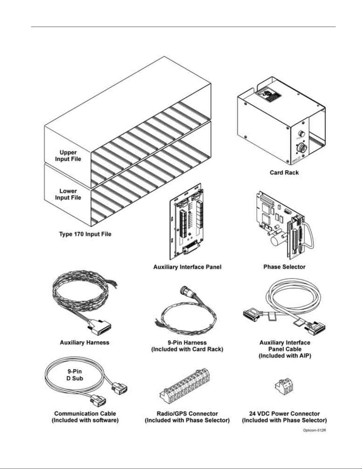
Figure 3-1 shows the phase selector installation
components including the phase selector, card
rack, input file, auxiliary interface panel, and the
wiring harnesses and cables. The 9-pin harness
connects the card rack to the traffic controller. The
communication cable connects the phase selector
to a PC. Additional communication connections
are available on the auxiliary interface panel. The
auxiliary interface panel cable connects the phase
selector to the auxiliary interface panel. The
auxiliary harness connects green sense inputs to
the phase selector. The radio/GPS cable connects
the phase selector to the intersection radio/GPS
unit. A customer-supplied 24 VDC power cable
connects the phase selector to an external power
supply, which is required when the phase selector
is plugged directly into an input file of a traffic
controller cabinet that does not have 24 VDC on
the edge connector.
NOTE: Illustrations and connections to the
traffic controller may not be exactly as shown
or described in this manual. Refer to the
controller wiring diagram for correct terminal
connections.
The phase selector processes the signal from the
radio/GPS unit and activates outputs which are
connected to the preemption inputs on the traffic
controller. There are four channel outputs
accessible on the rear connector of the phase
selector and up to 12 additional channel outputs
accessible on the front of the phase selector.
Each channel output delivers a constant output for
high priority activation, and a pulsed output for
low priority activation. A high priority signal
received on a channel will override any low
priority activation. In certain modes of operation,
outputs may be activated that are dependent on
the state of the requesting vehicle’s turn signal.
Another mode provides separate outputs for high
priority and low priority. The use of an auxiliary
interface panel is required to access these
additional modes and outputs.
Intersection Equipment Installation Instructions 11
Figure 3-1. Phase Selector Installation Components

12 Intersection Equipment Installation Instructions
4 Features
The Opticom™ GPS System Phase Selector has
the following features:
• High and Low priority vehicle discrimination
• First come, first served priority within each
priority level
• Plugs directly into input files
• User-settable range threshold settable by ETA
and/or distance
• Easily installed
• Compatible with most traffic controllers
• Computer-based user interface
– RS-232 communication port
– Customizable range thresholds
– Customizable ID code validation
– Customizable timing parameters
– Detailed current system parameter
information
– History log of most recent activities
(10,000 entries)
• 150,000 vehicle class/vehicle code ID
combinations
• 254 Agency IDs
• Front panel switches and diagnostic
indicators for testing
Intersection Equipment Installation Instructions 13
5 Installation
This section describes the installation of
intersection equipment. There are two models of
the Radio/GPS unit. See section 5.2.1 for details
on installing the Model 1012 Radio/GPS unit.
5.1 Model 1010 Radio/GPS unit mounting
Location Considerations
Read and understand the following precautionary
paragraphs before starting the installation.
• The Model 1010 radio/GPS unit should be
mounted in a location that has an
unobstructed view of all approaches out to a
distance of 2500 feet.
• Blockage of approaches by things such as
bridges, buildings, walkways, and trees should
be avoided.
• The Model 1010 radio/GPS unit is usually
mounted to the mast arm or span wire pole
nearest the traffic controller cabinet. If an
appropriate mounting location on a mast arm
or span wire pole is not available, you can
mount the unit to a span wire. Try to use a
signal head or sign mount to minimize sway.
• The Model 1010 radio/GPS unit should be
mounted level and as high as possible. Do
not mount the unit upside down.
• The Model 1010 radio/GPS unit should have
an unobstructed view of at least 50% of the
sky.
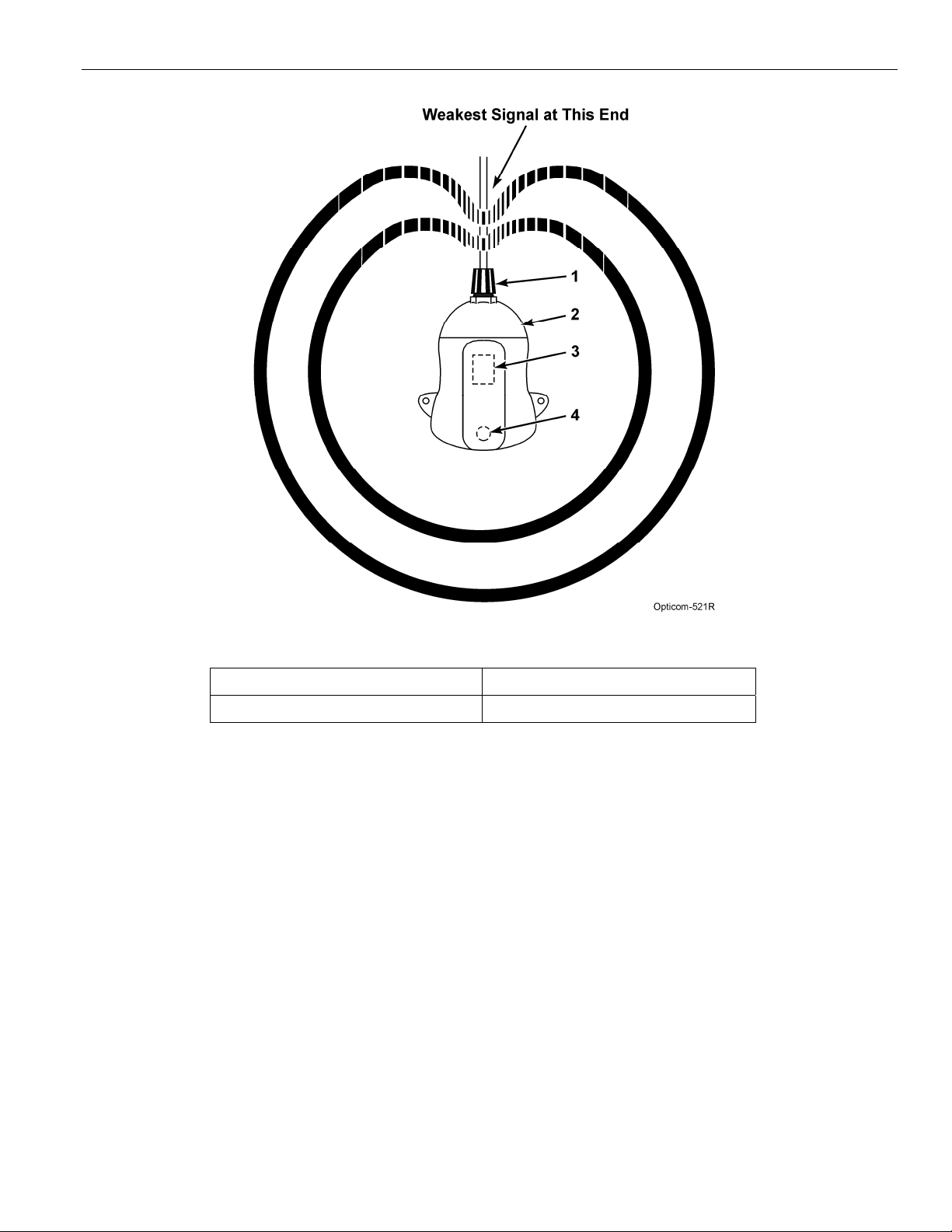
• The Model 1010 radio/GPS unit should be
oriented such that the cable retainer is facing
an area from which vehicles will NOT be
approaching. See Figure 5-1.
• Do not paint the Model 1010 radio/GPS unit
cover. Metals or metal oxides in the paint may
interfere with GPS reception and/or radio
reception/transmission.
• Do not modify the radio/GPS unit circuitry.
There are no user-serviceable parts inside.
IMPORTANT NOTE
Modifying the radio/GPS unit may seriously
damage the equipment and void the warranty.
Do not attempt to modify the radio/GPS
circuitry in any way. Modifying the radio and/or
antenna in any way may cause the radio to
violate FCC/IC requirements.
REMARQUE IMPORTANTE
La modification du système radio/GPS risque
d’endommager sérieusement le matériel et
d’annuler la garantie. Ne pas tenter de modifier
les circuits du système radio/GPS de quelque
façon que ce soit. En modifiant le système radio
et/ou l’antenne de quelque façon que ce soit, la
radio risque de ne plus répondre aux exigences
de la FCC/IC.
• The mounting location should be such that
the cable run from the radio/GPS unit to the
phase selector (located in the traffic controller
cabinet) is no more than 250 feet.
• The radio/GPS cable may be run through
conduit or attached to a messenger wire. The
cable should not be suspended unsupported.
14 Intersection Equipment Installation Instructions
Figure 5-1. Radio Signal Pattern
1. Cable retainer 3. GPS antenna
2. Intersection radio/GPS unit 4. Radio antenna
Intersection Equipment Installation Instructions 15
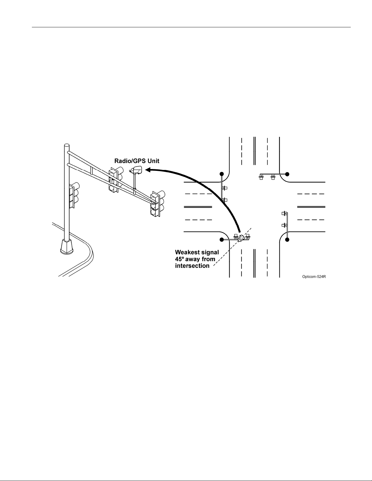
Figures 5-2 through 5-4 show typical installations
of the Opticom™ GPS System Intersection Model
1010 Radio/GPS Units.
Figure 5-2 shows a Model 1010 radio/GPS unit
installed on a mast arm. The radio/GPS unit should
be mounted level and higher than the mast arm
pole, if possible. Place the unit as far out over the
intersection as possible and still provide good
coverage down the cross streets.
Figure 5-2. Mast Arm Installation Model 1010
16 Intersection Equipment Installation Instructions
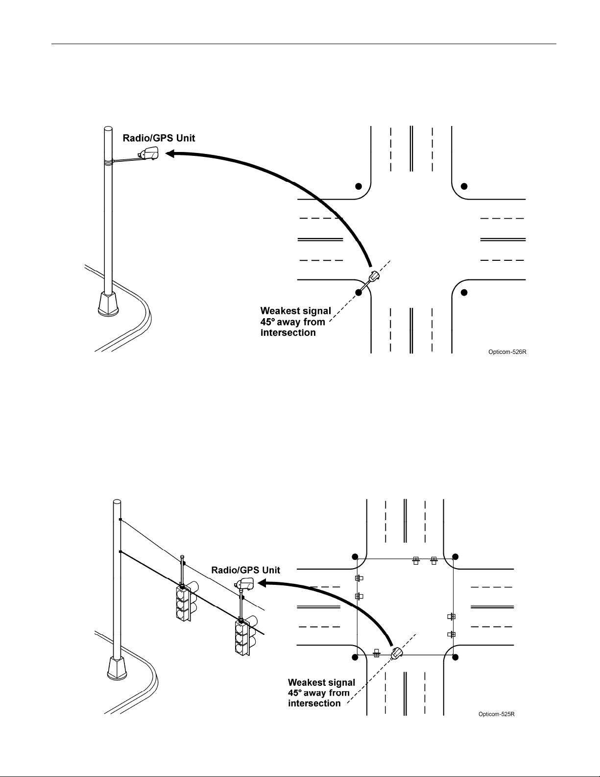
Figure 5-3 shows a radio/GPS unit installed on a
span wire pole. The radio/GPS unit should be
mounted level and extended about 3 feet away
from the pole.
Figure 5-3. Span Wire Pole Installation Model 1010
Figure 5-4 shows a Model 1010 radio/GPS unit
installed on a span wire. The radio/GPS unit
should be mounted level and higher than the
upper span wire. Mount the unit so that it is as
rigid and stable as possible.
Note: This method should only be used if other
methods are not available.
Figure 5-4. Span Wire Installation Model 1010
Intersection Equipment Installation Instructions 17
5.2 Model 1010 Radio/GPS Unit
Installation
This section describes how to install the
Opticom™ GPS System Model 1010 Radio/GPS
Unit. See section 5.2.1 for details on installing the
Model 1012 Radio/GPS unit.
NOTE: The mounting location must provide a
3/4-inch NPT internal thread mount. Mounting
brackets, nipples, pipe and lock nuts are not
included.
Choose the mounting location. This is usually the
mast arm or span wire pole nearest the traffic
controller cabinet. The cable run from the
radio/GPS unit to the phase selector (located in
the traffic controller cabinet) should not exceed
250 feet.
Screw a nipple (or pipe) into the base of the
radio/GPS unit. Use pipe thread tape to
waterproof the joint.
Loosen the two cover screws and remove the
wiring cover.
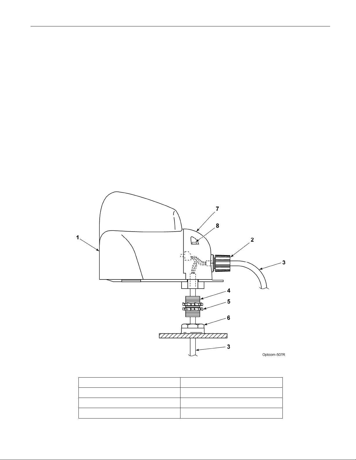
Route the radio/GPS cable from the radio
mounting location to the traffic controller cabinet.
The cable can enter the radio/GPS unit either
through the cable retainer in the wiring cover or
through the nipple/pipe at the base of the unit.
See Figure 5-5. In either case, the wiring
connections are the same.
For purposes of discussion, these instructions
assume the cable enters the radio/GPS unit
through the cable retainer.
Figure 5-5. Model 1010 Radio/GPS Unit Mounting
1. Intersection radio/GPS unit 5. Locknut (2)
2. Cable retainer 6. 3/4-inch NPT mount
3. Radio/GPS cable 7. Wiring cover
4. Nipple/Pipe 8. Cover screws (2)
 Loading...