

Page 1

User manual
Model:IR-U-POEv3/12
Brand:GTSYS R.I.A.
Page 2

Table of Contents
1 Getting Acquainted...................................................................................................................................1
2 Installing the IR-U-POEv3/12 ..........................................................................................................2
2.1 Installation pre-requirements.............................................................................................................2
2.2 Software installation..........................................................................................................................2
2.3 Install the device ..........................................................................................................................
3 Start APToolUniversal..............................................................................................................................4
3.1 Test Setup..........................................................................................................................................5
3.2 Approval Carrier test.........................................................................................................................5
3.3 Approval Frequency Hopping...........................................................................................................6
3.4 Reading Tags.....................................................................................................................................7
3.5 Writing Tags......................................................................................................................................8
4 Set IP-Address Dialogue...........................................................................................................................9
4.1 To set the reader IP-Address..............................................................................................................9
5 Set Password Dialogue..............................................................................................................................10
5.1 To set a password...............................................................................................................................10
5.2 To reset the password ( to default )...................................................................................................10
6 Set Power Dialogue.................................................................................................................................11
6.1 To set the power level......................................................................................................................11
7 Menu........................................................................................................................................................12
7.1 Main menu.......................................................................................................................................12
7.2 Application short-cuts......................................................................................................................12
8 About.......................................................................................................................................................13
3
Page 3

Quick Reference Guide
1 Getting Acquainted
Congratulations on purchasing a GTSYS Integraded RFID Reader. The reader can be delivered for 860 – 960
MHz (subject to regulatory region). The supported protocols are EPC Class1Gen2 / ISO18000-6C.
It has been verified to work with tags from:
• Alien
• Avery Dennison
• Impinj
• Mikoh
• RSI/Sirit
• TI
• UPM Raflatac
• Star Systems International
The read range is up to 10m, depending on the tag used and power setting.
Use this guide for more information on setting up your RFID Reader and learning how it works.
Next Chapter: Installing the IR-U-POEv3/12
Install the APToolUniversal software. The software program can be copied from the CD to your PC.
Page 4
Quick Reference Guide
2 Installing the IR-U-POEv3/12
2.1 Installation pre-requirements
• PC with a minimum Pentium 4 class CPU
• Microsoft ® Windows 7, Linux or MAC
• 100 MB available hard drive space
• Ethernet TCP/IP network with DHCP service
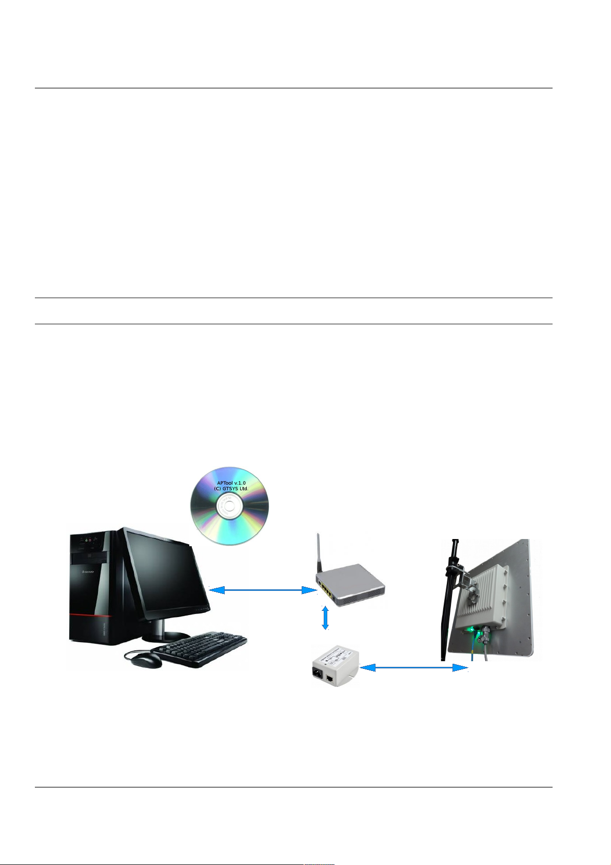
2.2 Software installation
For the reader to work properly, install the programs on your computer before you connect your Reader to your
computer.
1. Insert the accompanying CD into the CD tray of your computer.
2. Start the APTool-installer-v3.0.0.exe program from the CD and follow the instructions in the installation
wizard.
3. Make sure your PC is connected to the same network as the Integrated RFID Reader.
4. Install the Integrated RFID Reader to a proper mounting pole and connect the Ethernet port with the
PoE-Injector. The Injectors data port must connected to the network with DHCP service available.
Power-up the PoE-Injector.
RFID Reader
Access point
PoE-Injector
PC (running Windows 7)
Page 5
install the device
Quick Reference Guide
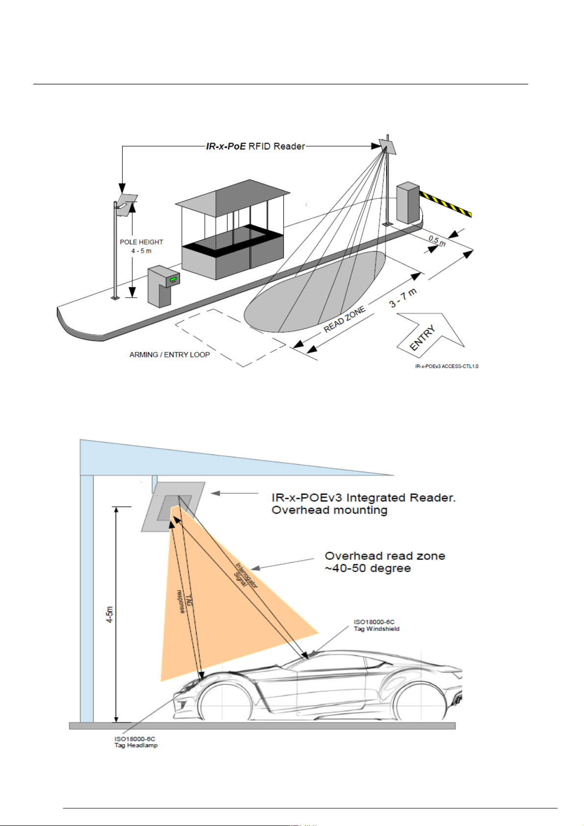
2.3 Install the device
EXAMPLE OF ENTRANCE LANE LAYOUT FOR ACCESS CONTROLL AND PARKING
EXAMPLE OF OVERHEAD MOUNTED IR-x-POEv3
FREEFLOW TOLLING AT 100-120 KM/H
Next chapter: 3Start APToolUniversal
Page 6

Quick Reference Guide
3 Start APToolUniversal
GTSYS provides a testtool: APToolUniversal. It is available from the Start menu after the
installation process has sucessfully finished. The path to the program is: Start -> Program ->
APToolUniversal
APToolUniversal can't discover the reader automatically. After the reader had completely
started the LED show a static green in combination with a heart-beat blue. At this stage the
reader had retrieved a IP address from the DHCP server or use the Discovery-tool comes with
the software installation. The MAC address is written on a label next to the RJ45 Ethernet port.
Connect the tool to the reader using the Settings menu tab and select "Set IP Address" see
chapter 8 for details.
Illustration 1: APToolUniversal Start-up Screen
Illustration 2: Reader Discovery
Page 4 / 13
Page 7

Quick Reference Guide
3.1 Test Setup
The first steps to start with:
• Enter the IP address shown in the Discovery-tool see page 8 - chapter 4.1 for details.
• Set the Test to run. (FCC)
• Set the antenna type used 12dbi
The power level will be set automatically for the test region depending on the selected
antenna.
3.2 Approval Carrier test
Depending on your selection FCC you are able to select the dedicated
Frequencies:
FCC: 902.75 Mhz 912.75 Mhz 927.75 Mhz
with or without a modulated carrier.
To proceed with the carrier test:
• Select the tab 'Carrier Test'
• Use the Combox to select the frequency.
• Select 'Modulation on' for a modulated carrier.
• If needed adjust the powerlevel (see page 10 - 6.1To set the power level)
• Click the 'Start' button to make the IR-x-POE running in the test mode.
The carrier indication Icon change from 'Carrier off' to 'Carrier on'
• Click the 'Stop' to stop the test, the carrier indication Icon change from 'Carrier on' to
'Carrier off'
Page 5 / 13
Page 8

3.3 Approval Frequency Hopping
Quick Reference Guide
Test the frequency hopping behavour of the RFID reader. In this mode the reader change the
frequency and hopping over the channels defined.
FCC: 50 channel.
To proceed with the frequency hopping test:
• Select the tab 'Hopping Test'
• Set the power if needed (see page 10 - 6.1To set the power level)
• Click the 'Start' button to make the RFID reader run the test mode.
The carrier indication Icon change from 'Carrier off' to 'Carrier on'
• Click the 'Stop' to stop the test.
The carrier indication Icon change from 'Carrier on' to 'Carrier off'
Page 6 / 13
Page 9

Quick Reference Guide
3.4 Reading Tags
The APTool allows you to read information from a RFID tag.
To proceed with reading:
• Put a RFID tag in front of the the reader.
• In APTool select the "RFID Read" tab.
• Set the reading option (see below)
• Click the "Read" button to read selected informations from the RFID tag.
Read options:
• Read EPC (default)
• Read TID (optional)
• Read Bank 3 (optional)
in Text or Hex view
Illustration 3: RFID Read tab
Problem cannot read TID or Bank3
• The RFID tag may be password protected.
Please refer to page 9 – Set Password Dialogue
• RFID tag may be out of read range – reposition the tag.
Page 7 / 13
Page 10

Quick Reference Guide
3.5 Writing Tags
The APTool allows you to write information to the Bank3 user memory of a RFID tag.
To proceed with writing onto the tag:
• Put a RFID tag onto the reader
• Read the tag (see Reading Tags)
• Select the "RFID Write" tab and write information in the input line
• Click the "Write" button
Illustration 4: RFID Write Tab
The RFID tag might be password protected.
Problem write failed!
• Reason: Power setting may be too low.
Please refer to page 10 – Set Power Dialogue to adjust the power settings.
• Reason: Tag may be password protected.
Please refer to page 9 – Set Password Dialogue
Page 8 / 13
Page 11

Quick Reference Guide
4 Set IP-Address Dialogue
To connect the APTool with the integrated RFID reader via TCP/IP you must know the readers IPAddress. This can be determined from the leases table of the DHCP server. The readers MAC address is
written on a label close to the RJ45 Ethernet connector
4.1 To set the reader IP-Address
• Select “Settings->Set IP-Address” from the top menu bar
• Type a IPv4 dotted decimal address to the input field
• Click on “OK”
Illustration 5: Set IP-Address
Notice:
If a connection had been established, the network icon in the status bar changed
from
→
and the current IP address is show.
Page 9 / 13
Page 12

Quick Reference Guide
5 Set Password Dialogue
The EPC/Gen2 RFID tags have a feature to protect information with a password this dialogue
allows you set a password while reading or writing onto a RFID tag.
Password input in hexadecimal charters (0-9,a-f) with a length of 8, the default value is 00000000
5.1 To set a password
• Select “Settings->Set Password” from the top menu bar
• Type a 8 charter hexadecimal password
• Click on “OK”
5.2 To reset the password ( to default )
• Select “Settings->Set Password” from the top menu bar
• Type “00000000” into the input line
• Click on “OK”
Illustration 6: Password Dialogue
Page 10 / 13
Page 13

Quick Reference Guide
6 Set Power Dialogue
Depending on the environment and the RFID tag in use, you need to adjust the power setting
of the reader's amplifier to read and write successfully.
Notice: High power values can have a negative effect to the read/write results – it is recommend to start
from low (min) to high (max) power values in small steps to find the optimal setting.
6.1 To set the power level
• Select “Settings->Set Power” from the top menu bar
• Use the slide bar to set the power level
• Click on “OK”
Illustration 7: Set Power Dialogue
Output power range:
Min = 10 dbm
Max = 30 dbm
Stepping = 1 dbm
Page 11 / 13
Page 14

7 Menu
APTool menu and shortcuts.
7.1 Main menu
APTool comes with 3 menu items:
• File
* Exit application
• Settings
* Set IP-Address
* Set Power
* Set Password
• Help
* About
Quick Reference Guide
7.2 Application short-cuts
APTool Software Functions
Alt-F File Menu
Alt-S Settings Menu
Alt-H Help / About
Alt-R Activate Read Tab
Alt-W Activate Write Tab
Alt-T Set/unset TID read
Alt-S Set/unset Bank3 read
Ctrl-X Exit program
Ctrl-H About
Ctrl-I Set IP-Address
Ctrl-P Power Dialogue
Ctrl-A Password Dialogue
Page 12 / 13
Page 15

8 About
The copyright information.
Quick Reference Guide
Illustration 8: Copyright notice
Page 13 / 13
Page 16

FCC Caution.
This device complies with part 15 of the FCC Rules. Operation is subject to the following two
conditions: (1) This device may not cause harmful interference, and (2) this device must accept
any interference received, including interference that may cause undesired operation.
Any Changes or modifications not expressly approved by the party responsible for compliance
could void the user's authority to operate the equipment.
Note: This equipment has been tested and found to comply with the limits for a Class B digital
device, pursuant to part 15 of the FCC Rules. These limits are designed to provide reasonable
protection against harmful interference in a residential installation. This equipment generates
uses and can radiate radio frequency energy and, if not installed and used in accordance with the
instructions, may cause harmful interference to radio communications. However, there is no
guarantee that interference will not occur in a particular installation. If this equipment does
cause harmful interference to radio or television reception, which can be determined by turning
the equipment off and on, the user is encouraged to try to correct the interference by one or
more of the following measures:
-Reorient or relocate the receiving antenna.
-Increase the separation between the equipment and receiver.
-Connect the equipment into an outlet on a circuit different from that to which the receiver is
connected.
-Consult the dealer or an experienced radio/TV technician for help.
This equipment complies with FCC radiation exposure limits set forth for an uncontrolled
environment. This equipment should be installed and operated with minimum distance 20cm
between the radiator & your body.
 Loading...