

Page 1
INSTALLATION INSTRUCTIONS FOR
L
I
S
T
E
D
US
GTO/PRO SL-5100 and GTO/PRO SL-6100
Advanced AC Powered Slide Gate Operators
WARNING!
• READ ALL INSTRUCTIONS COMPLETELY before attempting
installation and use; failure to do so may result in serious injury or death!
• This unit must only be installed by an experienced technician!
•DANGER: HIGH VOLTAGE! Contact with gate operator circuitry
can cause serious injury or death! Operator power must be
disconnected before servicing!
• This gate operator produces a high level of force. Stay clear of the unit
while it is operating and exercise caution at all times.
This product meets and exceeds the requirements of UL 325, the standard which regulates gate operator safety,
as established and made effective March 1, 2000, by Underwriters Laboratories Inc.
DO NOT Install This Operator Without Roller Guards And Safety Edges!
© 2000 GTO, Inc.
3121 Hartsfield Road • Tallahassee, Florida 32303
Telephone (800) 543-GATE or (850) 575-0176 • Fax (850) 575-8912 • www.gtoinc.com
rev - 04/12/01
RB939
Page 2

The GTO/PRO SL-5100 and SL-6100 automatic slide gate operators are intended for use with vehicular slide
gates. The operators can be used in Class I, II, III, and IV applications.
VEHICULAR GATE OPERATOR CLASS CATEGORIES
Residential Vehicular Gate Operator-Class I: A vehicular gate operator (or system) intended for use in
a home of one-to-four single family dwelling, or a garage or parking area associated therewith.
Commercial/General Access Vehicular Gate Operator-Class II: A vehicular gate operator (or system)
intended for use in a commercial location or building such as a multifamily housing unit (five or more single
family units), hotel, garages, retail store, or other building servicing the general public.
Industrial/Limited Access Vehicular Gate Operator–Class III: A vehicular gate operator (or system)
intended for use in an industrial location or building such as a factory or loading dock area or other locations
not intended to service the general public.
Restricted Access Vehicular Gate Operator–Class IV: A vehicular gate operator (or system) intended for
use in a guarded industrial location or building such as an airport security area or other restricted access
locations not servicing the general public, in which unauthorized access is prevented via supervision by
security personnel.
Conversion Chart
Converting Metric Units to English Equivalents
When You Know Multiply By To Find Symbol
centimeters 0.3937 inches in. (or ")
meters 3.2808 feet ft. (or ')
kilograms 2.2046 pounds lb. (or #)
Converting English Units to Metric Equivalents
When You Know Multiply By To Find Symbol
inches 2.5400 centimeters cm
feet 0.3048 meters m
pounds 0.4535 kilograms kg
Temperature
deg. Celsius (ºC x 1.8) + 32 deg. Fahrenheit ºF
deg. Fahrenheit (ºF-32) / 1.8 deg. Celsius ºC
Page 3

TABLE OF CONTENTS
Gate Operator Class Categories ....................................................................................................................Inside Cover
Metric Conversion Chart .......................................................................................................................................................Inside Cover
Safety Instructions for the GTO/PRO-SL-5100 and GTO/PRO SL-6100 Slide Gate Operators ....................................... 1
Important Safety Instructions for the System Designer ......................................................................................................................... 1
GTO Foot Pedal Release........................................................................................................................................................................ 1
Important Safety Instructions for the Installer ...................................................................................................................................... 2
Important Safety Instructions Specific to Secondary Means of Protection Against Entrapment ............................................................ 3
Important Safety Instructions for the Consumer/End User.................................................................................................................... 4
Required Safety Precautions for Gates.................................................................................................................................................. 5
Warning Labels ..................................................................................................................................................................................... 6
Technical Specifications .................................................................................................................................................. 7
Parts Identification.........................................................................................................................................................8
Installing the Gate Operator ..........................................................................................................................................9
Preparation of the Gate ........................................................................................................................................................................ 9
Operator Installation Overview ............................................................................................................................................................. 9
Using the Mounting Template ............................................................................................................................................................. 10
Removing the Operator Housing......................................................................................................................................................... 11
Mounting the Operator ....................................................................................................................................................................... 11
Installing the Chain .............................................................................................................................................................................11
Connecting Power to the Operator ......................................................................................................................................................12
Adjusting the Limit Switches ........................................................................................................................................ 13
Advanced Gate Operator Control Board ...................................................................................................................... 14
Control Board Settings ........................................................................................................................................................................ 15
Advanced Control Board Features................................................................................................................................ 18
Setting a Personal Transmitter Code............................................................................................................................ 19
Mounting the Receiver ................................................................................................................................................. 19
Reinstalling the Operator Housing .............................................................................................................................. 20
Compatible Safety Devices ........................................................................................................................................... 21
Installing a Dual Slide Gate System ............................................................................................................................ 22
Maintenance................................................................................................................................................................. 25
Trouble Shooting Guide ............................................................................................................................................... 26
Warranty and Repair Service .......................................................................................................................................27
Installation Check List .....................................................................................................................................Back Cover
Page 4
Important Safety Instructions
SAFETY INSTRUCTIONS FOR THE GTO/PRO SL-5100 AND GTO/PRO SL-6100 SLIDE GATE OPERATORS
Because automatic gate operators produce high levels of force, all system designers, installers, and consumers have
an obligation to know the potential hazards associated with improperly designed, installed, or maintained gate operator
systems. Keep in mind that the gate operator is just one component of the total gate operating system. Each component
must work in unison to provide the consumer with convenience, security, and safety.
This manual contains various safety precautions and warnings for the system designer, installer, and consumer.
Because there are many possible applications of the gate operator, the safety precautions and warnings contained in
this manual cannot be completely exhaustive in nature. They do, however, provide an overview of the safe design,
installation, and use of this product. CAREFULLY READ AND FOLLOW ALL SAFETY PRECAUTIONS,
WARNINGS, AND INSTALLATION INSTRUCTIONS TO ENSURE THE SAFE SYSTEM DESIGN,
INSTALLATION, AND USE OF THIS PRODUCT.
The precautions and warnings in this manual are identified with these warning symbols.
This symbol identifies the conditions that can result in serious injury or death from electrical shock.
This symbol identifies the conditions that can result in damage to the operator or its components, serious injury,
or death.
Because GTO automatic gate operators are only part of a total gate operating system, it is the responsibility of
the designer, installer, and purchaser to ensure the total system is safe for its intended use. Bypassing safety
devices or neglecting to use safety devices with the gate operator is NOT acceptable.
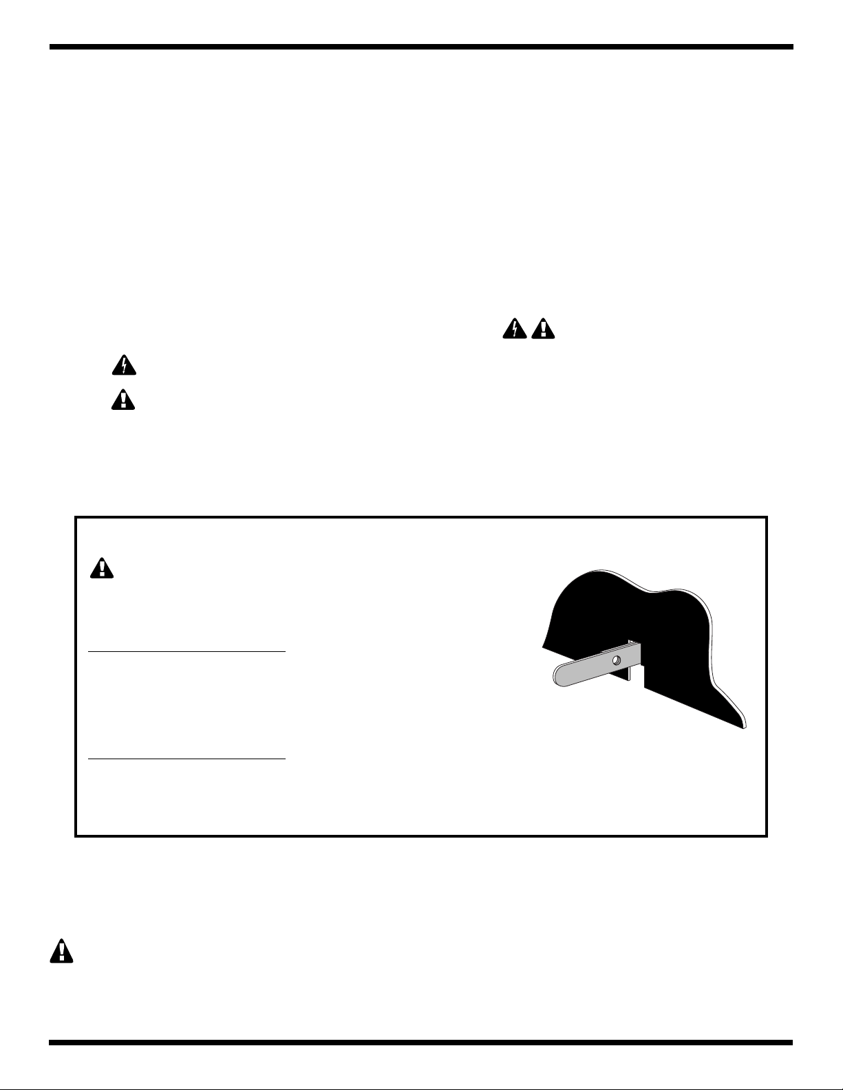
Use the GTO FOOT PEDAL RELEASE (Patented) to Manually Operate the Gate
CAUTION: NEVER attempt to operate the foot pedal release
while the gate is in motion. DO NOT attempt to operate the gate with
a transmitter or other activation device while the foot pedal is in use.
To disengage the gate operator:
Place your foot on the pedal, then step down and push the pedal to the right
until it stops against the operator frame. Lift foot from pedal. This
procedure disengages the chain sprocket and allows the gate to be opened
and closed manually.
To re-engage the gate operator:
Place your foot on the pedal, then step down and push the pedal to the left until it stops against the operator frame.
Lift foot from pedal. This procedure re-engages the chain sprocket and allows the operator to drive the gate.
The foot pedal release can be secured with a Master
®
pin lock (accessory available from your GTO dealer).
IMPORTANT SAFETY INSTRUCTIONS for the System Designer
WARNING: To reduce the risk of injury or death:
1. READ AND FOLLOW ALL INSTRUCTIONS.
2. This operator is intended for use only on vehicular gates. Pedestrians must be supplied with a separate walk-
through gate (see Entrapment Protection on page 5).
3. When designing a system that will be entered from a highway or main thoroughfare, make sure the system
is placed far enough from the road to prevent traffic congestion.
1
Page 5

Important Safety Instructions
IMPORTANT SAFETY INSTRUCTIONS for the Installer
WARNING–To reduce the risk of injury or death:
I. Before Installation
1. READ AND FOLLOW ALL INSTRUCTIONS.
2. Verify this operator is proper for the type and size of gate, and its frequency of use.
3. Make sure that the gate has been properly installed and slides freely in both directions. Repair or replace all
worn or damaged gate hardware prior to installation. A freely moving gate will require less force to operate
and will enhance the performance of the operator and the safety devices used with the system.
4. All openings of a horizontal slide gate must be guarded or screened to prevent a 2
passing through openings anywhere in the gate. This screen (or guard) must also be installed over the portion
of adjacent fence that the gate covers in the open position (see page 5).
5. Review the operation of the system and become familiar with its safety features. Understand how to disengage
and re-engage the operator with the foot pedal release (see GTO Pedal Release on page 1).
6. This gate operator is intended for vehicular gates ONLY. A separate entrance or gate must be installed for
pedestrian use (see page 5). NO ONE SHOULD CROSS THE PATH OF A MOVING GATE.
II. During Installation
1. Install the gate operator on the inside of the property and fence line. DO NOT install an operator on the outside
of the gate where the public has access to it.
2. Be careful with moving parts and avoid close proximity to areas where fingers or hands could be pinched.
3. Determine the best obstruction sensing setting for this installation. The gate MUST stop and reverse on contact
with an obstruction or when an object activates the non-contact sensors. After adjusting the force or the limit
of travel, retest the gate operator. Failure to adjust and retest the gate operator properly can increase the
risk of injury or death.
4. Additional safety equipment such as roller guards and safety edges (or photoelectric sensors) MUST
be installed to prevent bodily injury (see page 9).
1
/4 inch diameter sphere from
5. Mount access controls away from the gate (minimum distance is 10 feet). The user must have full view of
the gate but be unable to touch it while operating the controls.
6. Secure outdoor or easily accessed gate operator controls in order to prohibit unauthorized use of the gate.
III. After Installation
1. Review ALL safety instructions with the consumer/end user and explain the basic operation and safety
systems of the entire gate operator system, including operation of the foot pedal release.
2. Inform the consumer/end user that servicing of the operator must only be done by an experienced technician.
3. Attach the warning signs (included) to each side of the gate to alert public of automatic gate operation. Take
a photo of warning signs installed on gate. Record the date of the photo for your reference.
4.
SAVE THESE INSTRUCTIONS. Leave IMPORTANT SAFETY INSTRUCTIONS
(included) with consumer/end user.
2
Page 6

Important Safety Instructions
IMPORTANT SAFETY INSTRUCTIONS Specific to Secondary
Means of Protection Against Entrapment
As specified by Underwriters Laboratories Inc. UL 325 (30A.1.1), automatic gate operators shall have provisions for,
or be supplied with, at least one independent primary and one independent secondary means to protect against
entrapment. GTO gate operators utilize Type A, an inherent entrapment sensing system, as the primary type of
entrapment protection. The GTO/PRO SL-5100 and GTO/PRO SL-6100 operators have provisions for the connection
of Type B1, B2, or D protection to be used as the secondary type of entrapment protection.
1. For gate operators utilizing a non-contact sensor (Type B1) in accordance with UL 325 (51.8.4 [h]):
A. Refer to the sensor manufacturer’s instructions on the placement of non-contact sensors for each type of
application.
B. Care shall be exercised to reduce the risk of nuisance tripping, such as when a vehicle trips the sensor while
the gate is still moving.
C. One or more non-contact sensors shall be located where the risk of entrapment or obstruction exists, such as
the perimeter reachable by a moving gate or barrier.
2. For gate operators utilizing a contact sensor (Type B2) in accordance with UL 325 (51.8.4 [i]):
A. One or more contact sensors shall be located at the leading edge, trailing edge, and post mounted both inside
and outside of a vehicular slide gate system.
B. A hard wired contact sensor shall be located and its wiring arranged so that the communication between the
sensor and the gate operator is not subjected to mechanical damage.
C. A wireless contact sensor such as one that transmits radio frequency (RF) signals to the gate operator for
entrapment protection functions shall be located where the transmission of the signals are not obstructed or
impeded by building structures, natural landscaping or similar obstruction. A wireless contact sensor shall
function under the intended end-use conditions.
3. For gate operators utilizing an actuating device requiring continuous pressure to maintain opening or closing motion
of the gate (Type D) in accordance with UL 325 (51.8.4 [e]):
A. The gate operator controls must be placed so that the user has full view of the gate area when the gate is moving.
B. Warning signs (see page 6) shall be placed adjacent to the controls.
C. An automatic closing device (timer, loop sensor, etc.) shall not be employed.
D. No other activation device shall be connected.
ENTRAPMENT ALARM (UL 325; 30A.1.1A)
The GTO/PRO SL-5100 and GTO/PRO SL-6100 operators are designed to stop and reverse for 2 seconds
when the gate comes in contact with an obstruction or when an object activates the non-contact sensors.
Additionally, these operators are equipped with an audio entrapment alarm which will function if the unit
obstructs twice while opening or closing. This alarm will sound for a period of 5 minutes or until the operator
receives an intended signal (e.g., transmitter signal) and the gate returns to a fully open or fully closed position.
3
Page 7
Important Safety Instructions
IMPORTANT SAFETY INSTRUCTIONS for the Consumer/End User
WARNING: To reduce the risk of injury or death:
1. READ AND FOLLOW ALL INSTRUCTIONS.
2. Distribute and discuss copies of the IMPORTANT SAFETY INSTRUCTIONS manual with all persons
authorized to use your gate. SAVE THESE INSTRUCTIONS.
3. Always keep people and objects away from the gate and its area of travel.
NO ONE SHOULD CROSS THE PATH OF THE MOVING GATE.
4. Your automatic gate is not for pedestrian use. If pedestrian traffic is expected near the gate, a walk-through
gate must be installed for this purpose (see page 5).
5. Do not allow children or pets near your gate. Never let children operate or play with gate controls. Keep
the remote controls away from children and unauthorized users; store controls where children and unauthorized
users cannot access them.
6. If push buttons or key switches are installed, they should be within sight of the gate, yet located far enough
from the gate (at least 10 feet) so the gate cannot be touched while in operation. Do not operate any control
without watching the movement of the gate.
7. Do not activate your gate operator unless you can see it and can determine that its area of travel is clear of
people, pets, or other obstructions.
8. If your gate has open rollers, be sure that roller guards have been installed to prevent hands and fingers from
being caught in the rollers (see page 5).
9. It is your responsibility to make sure that the installer posted warning signs on both sides of your gate. If any
of these signs or warning decals become damaged, illegible or missing, replace them immediately. Contact
your installer or GTO for replacements.
10. Verify that electric safety edge sensors or photoelectric sensors have been installed (see page 5). These safety
devices should be tested monthly.
11. KEEP GATES PROPERLY MAINTAINED. Have a qualified service person make repairs to the gate
hardware. NEVER REMOVE THE OPERATOR HOUSING.
12. DANGER: HIGH VOLTAGE! Contact with gate operator circuitry can cause serious injury or death!
DO NOT attempt to service this operator yourself; for service, contact your installer or another experienced
technician.
13. Have your gate operator tested monthly and serviced regularly by an experienced technician. The gate MUST
stop and reverse on contact with an obstruction or when an object activates the non-contact sensors. If these
functions are observed to operate improperly, discontinue use and have operator serviced immediately.
14. To operate this equipment safely, YOU must receive detailed instructions on the operation of the foot pedal
release (see GTO Foot Pedal Release on page 1). If you feel you have not received full and proper
instructions, contact your installer.
15. Use the foot pedal release only when the gate is not in motion. Do not operate the gate with a transmitter or
other activation device while the foot pedal is in use.
4
Page 8
Important Safety Instructions
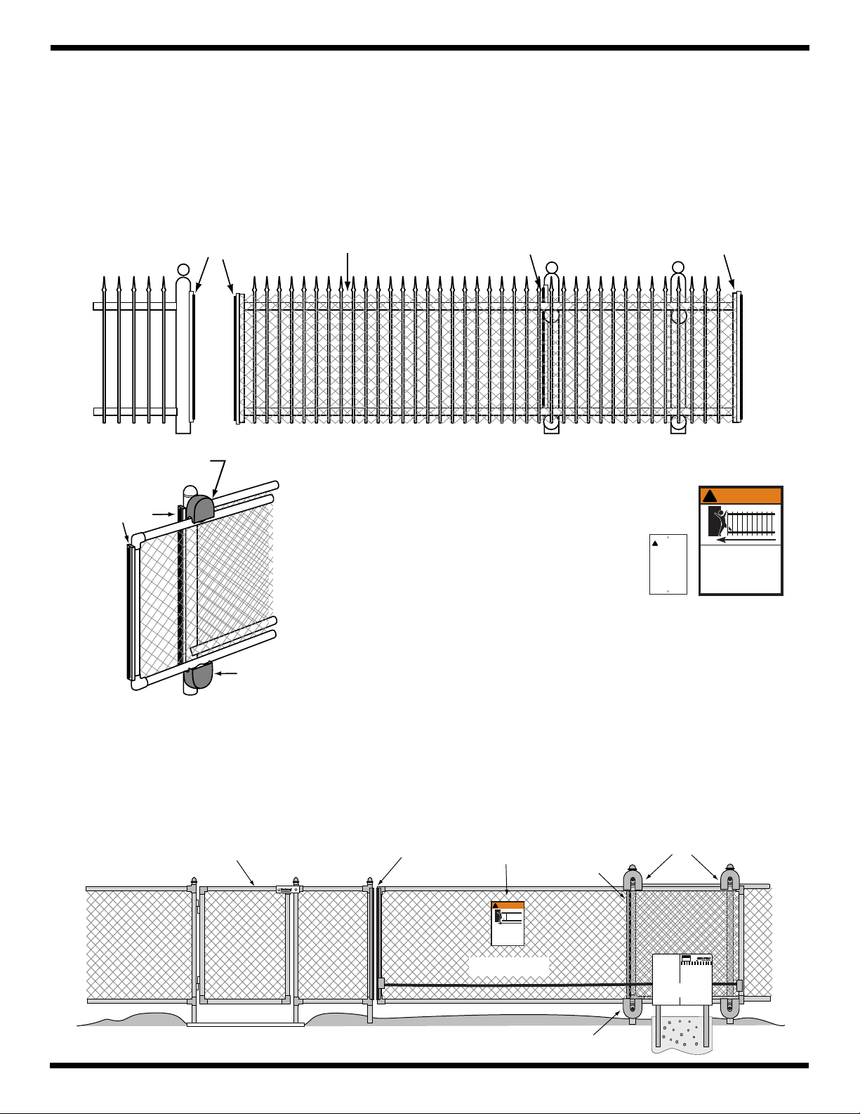
Required Safety Precautions for Gates
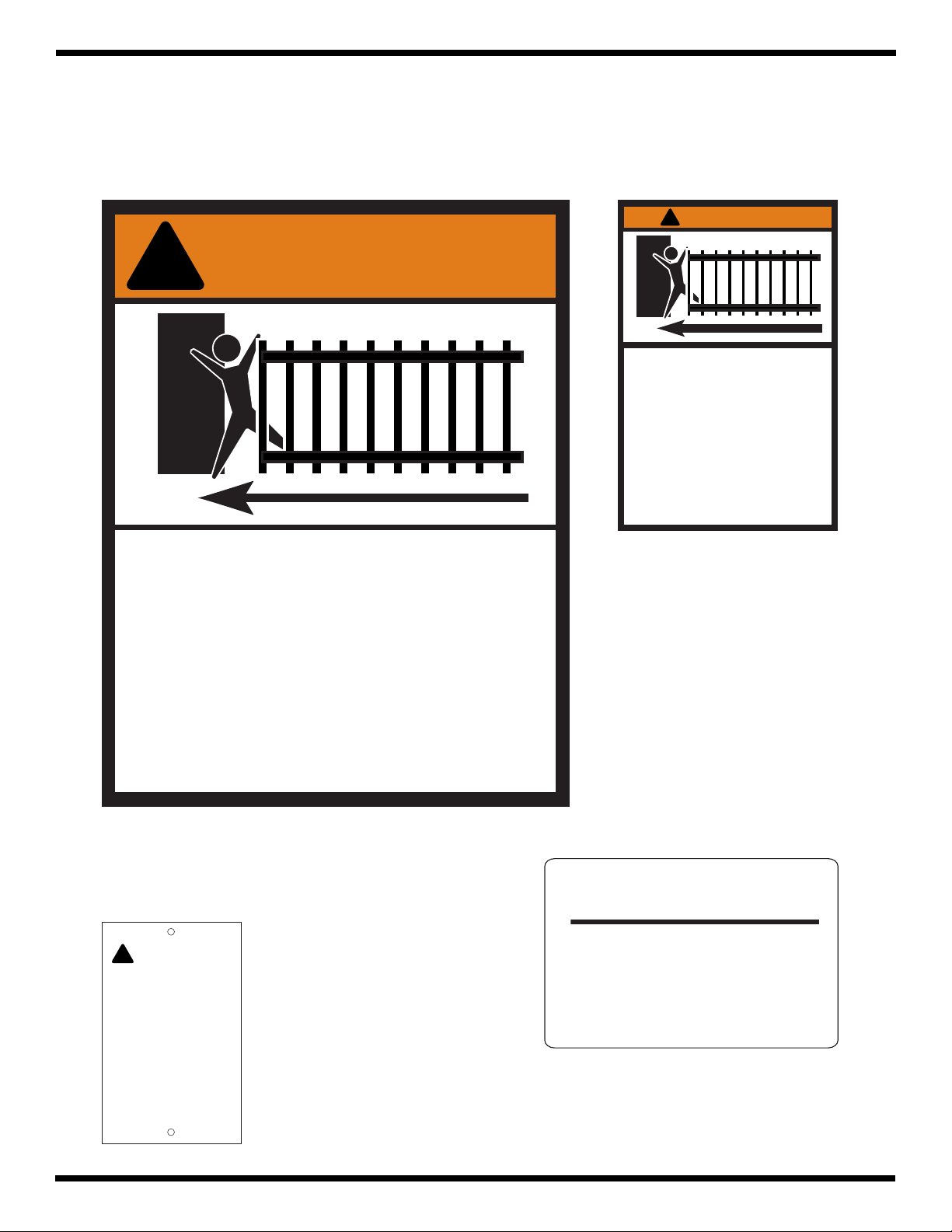
Install Screen Guard Over Gate and Fence
Injuries may occur when people put their hands, arms, legs, etc., through openings in the grill when the gate is operated,
trapping them between the grill and the fence post (or fence). All openings of a horizontal slide gate must be guarded
or screened to prevent a 2
must also be installed over the portion of adjacent fence that the gate covers in the open position. Screening will prevent
access through openings in areas where the gate travels.
1
” diameter sphere from passing through openings anywhere in the gate. This screen/guard
/4
Safety Edge
Roller guard to prevent
pinch point hazard.
Safety Edge
Screen Mesh
Roller Guards
Injuries occur when
hands become caught
between the gate and
the roller. Roller
guards and enclosed
tracks must be
installed to prevent
this pinch point
hazard.
Roller guard to prevent
pinch point hazard.
Safety Edge Safety Edge
!
WARNING
WARNING
!
Warning Signs
Moving Gate Can
Cause Injury Or
Death. Do Not Start
Gate Unless Path Is
Clear.
Entry controls should be
installed far enough from
the gate (at least 10 feet)
so that the user cannot touch
the gate while operating the
controls.
Moving Gate Can Cause
Injury Or Death
1. KEEP CLEAR! Gate may move at any time.
2. Do not allow children to operate gate or
play in gate area.
3. This gate is for vehicles only. Pedestrians
must use a separate entrance.
The large warning signs (with orange panel)
must be installed on both sides of the gate.
The small warning signs (above left) must
be installed adjacent to entry controls such
as keypads and push buttons (see page 6 for
details).
Entrapment Protection
GTO’s internal obstruction settings, even when properly adjusted, may not be sensitive enough to prevent bodily
injury. For this reason, safety devices such as safety edges MUST be installed. Furthermore, a walk-through gate
must be installed if pedestrian traffic is expected near the gate. We recommend the GTO Bulldog Pedestrian Gate
Lock (available as an accessory) for controlled access.
Pedestrian Gate
Safety Edge
5
Warning Sign
!
WARNING
Moving Gate Can Cause
Injury Or Death
1.KEEP CLEAR! Gate may move at any time.
2.Do not allow children to operate gate or
play in gate area.
3.This gate is for vehicles only. Pedestrians
must use a separate entrance.
Vehicle Gate
Safety Edge
Roller Guard
Roller Guard
®
CAUTION
AUTOMATIC GATE
STAND CLEAR
1-800-543-GATE
Operator
Page 9
Important Safety Instructions
Warning Labels
These warning signs and labels should be found at the locations specified below. If any of them are missing,
immediately contact your installer for replacements.
!
WARNING
!
WARNING
Moving Gate Can Cause
Injury Or Death
1. KEEP CLEAR! Gate may move at any time.
2. Do not allow children to operate gate or
play in gate area.
Moving Gate Can Cause
Injury Or Death
1. KEEP CLEAR! Gate may move at any time.
2. Do not allow children to operate gate or
play in gate area.
3. This entrance is for vehicles only.
Pedestrians must use a separate entrance.
4. Read the owner's manual and safety
instructions.
5. For gate operators using Type D entrapment
protection, an automatic closing device shall
not be employed.
warning label (1) installed on
operator housing
3. This gate is for vehicles only. Pedestrians
must use a separate entrance.
warning signs (2) to be installed on each side of the gate
(3–5 feet above the bottom of the gate)
WARNING
!
Moving Gate Can
Cause Injury Or
Death. Do Not Start
Gate Unless Path Is
Clear.
Entry controls should be
installed far enough from
the gate (at least 10 feet)
so that the user cannot touch
the gate while operating the
controls.
warning signs (2) to be placed
adjacent to an entry control
(such as a push button or
keypad)
Manual Operation of Gate
To manually open or close the gate,
step on Foot Pedal Release and push
it to the right. Use Foot Pedal Release
only when gate is NOT moving.
RB3272
manual operation instruction label (1)
installed on operator housing
6
Page 10

TECHNICAL SPECIFICATIONS
for the GTO/PRO SL-5100 & SL-6100 AC Gate Operators
Motor
• GTO/PRO SL-5100: 1/2 hp GTO-Leeson 1625 rpm TEFC; C-Face connection; 115 V, single phase.
• GTO/PRO SL-6100: 1 hp GTO-Leeson 1600 rpm TEFC; C-Face connection; 115 V, single phase.
Gear Reducer
• Totally enclosed 30:1, 60 series reducer, with vertical motor flange.
• Machine cut bronze gears run in an oil bath.
• Oil temperature range: –22 °F to 806 °F (–30 °C to 430 °C).
Power
• GTO/PRO SL-5100: 115 Vac, 60 Hz, 5 A; GTO/PRO SL-6100: 115 Vac, 60 Hz, 9.8 A.
• Requires copper conductors.
• Must be installed by a licensed electrician in accordance with National Electric Code (NEC)
and local codes.
• Product relies on a 15 A main disconnect circuit breaker (supplied by the installer).
• One 115 Vac GFCI outlet (located below control box) for additional accessories.
• Two 12 V back-up batteries provide up to 200 gate cycles in the event of a power failure.
Control
• Adjustable auto-close timer: 1 – 120 seconds.
• Independent obstruction settings for opening and closing cycles.
• Diagnostic and error condition LEDs.
• Potentiometers and DIP switches for easy adjustments.
• Six separate terminals for N/O contacts (e.g., safety edges or photoelectric beams).
• Mechanical limit controls.
• GTO remote mounted RF receiver tuned to 318 MHz (other receivers can be accommodated).
• Inverter provides soft start/soft stop gate movement and controls battery back-up feature.
Construction
• Zinc plated steel parts for maximum corrosion resistance.
• Mounting brackets can be welded or bolted.
• UHMW plastic guide rollers.
• GTO/PRO SL-5100 requires #40 chain; GTO/PRO SL-6100 requires #50 chain
(20’ chain included with each operator).
• Lockable foot pedal release (patented) allows manual operation of gate.
Operational Capacity
• Operator compatible with all types of horizontal slide gates
• GTO/PRO SL-5100: weight up to 1800 lb.; length up to 60 ft. (with an opening of 50 ft.)
• GTO/PRO SL-6100: weight up to 3000 lb.; length up to 60 ft. (with an opening of 50 ft.)
• Duty Cycle: Continuous.
Dimensions
• Housing: Width 20 in.; Depth 22 in.; Height 31 in.
• Control Box: Width 14 in.; Depth 6 in.; Height 16 in.
• Shipping Weight: GTO/PRO SL-5100 217 lb.; GTO/PRO SL-6100 223 lb.
7
Page 11

PARTS IDENTIFICATION
GTO/PRO SL-5100 and GTO/PRO SL-6100
AC Powered Slide Gate Operators
!
WARNING
Injury Or Death
®
AUTOMATIC GATE OPERATORS
Moving Gate Can Cause
Receiver (1)
GTO Transmitter (1)
Fully Assembled Operator
Chain Brackets (2)
S
D
R
A
D
L
N
A
D
T
S
I
5
2
E
S
3
L
T
®
U
o
t
s
m
r
o
f
n
o
C
8
7
1
1
n
tio
ra
e
p
l O
a
u
n
a
M
To manually open or close the gate,
step on Foot Pedal Release and push
it to the right. Use Foot Pedal Release
only when gate is NOT moving.
te
a
f G
o
2
7
2
3
B
R
0
9
9
Hardware
1/2" Nut (4)
Gate Warning Signs
(one for each side)
Entry Control
Warning Signs (2)
Chain (1)
Chain Adjuster Bolts (2)
IMPORTANT SAFETY INSTRUCTIONS
GTO/PRO SL-5100 & GTO/PRO SL-6100
AC Powered Slide Gate Operators
Installation Instructions for
GTO/PRO SL-5100 & GTO/PRO SL-6100
AC Powered Slide Gate Operators
WARNING
WARNING
Installation & Safety
Manuals
(1 each)
Ty Wraps (8)
8
Page 12

INSTALLING THE GATE OPERATOR
Safety Edges
Safety Edges or Photoelectric Beams
are Required
Roller Guard
Receiver
Roller Guard
Safety Edge
Operator
GTO/PRO
(REQUIRED)
Roller Guard
(REQUIRED)
(REQUIRED)
Safety Edge
Use Rigid Conduit
for inbound AC wire.
Chain Bracket
Chain Bracket
AC POWER
Photo Beam
Chain
Use PVC Conduit
for Receiver
(REQUIRED)
(REQUIRED)
(REQUIRED)
THIS UNIT MUST ONLY BE INSTALLED BY AN EXPERIENCED TECHNICIAN.
Preparation of the Gate
Before installing the GTO/PRO slide gate operator, make sure:
• the gate is properly installed.
• the gate is plumb, level, and moves freely.
• the gate does not bind or drag on the ground.
• the gate is screened if necessary (see page 5.)
• roller guards are installed (see page 5.)
Overview of the Operator Installation
The diagram below is an example of a single slide gate installation with required safety features. The operator must
be installed on the inside of the gate. You must install safety edges (or photoelectric sensors) and roller guards
(not included) to reduce the possibility of bodily injury.
NOTE: A separate gate or entrance must be installed for pedestrian use.
9
Page 13

Using the Mounting Template
The mounting template (see insert) is designed to simplify mounting the operator. It provides the installer with the
proper locations for running power and accessory wiring conduits. The template is also marked with the correct
distance between the operator mounting holes and shows the installer how to position the operator for the correct
clearance between the housing and the gate.
NOTE: The operator must be securely mounted on a level concrete pad. If you do not have an existing pad to work
with, be sure to install wiring conduit before pouring concrete. You must use (4)
washers, and nuts (not included) to mount the operator on the pad.
Study the mounting template. Lay the mounting template on the level concrete pad and mark the pad according to the
instructions on the template.
Before mounting the operator, check the following:
• The concrete pad is level.
• Four (4)
1
/2” diameter mounting anchors are in their correct positions.
• Conduit for power and accessory wiring is installed.
Installation Alignment
1
/2” diameter mounting anchors,
Safety Edges
(REQUIRED)
4" to 6"
Chain Bracket
Chain brackets must be installed (welded
or bolted) to provide 4 to 6 inches between
chain and inside of gate. This will insure
adequate clearance between the operator
housing and the gate.
Pad mounting holes line up with
chain idler wheels and should be
no closer than 4 inches and no
futher than 6 inches from the gate.
Driveway
Gate
Safety Edge
(REQUIRED)
C
L
Fence Post
Roller
Operator must be mounted with
the chain rollers and sprocket
aligned with the chain.
Fence Post
Roller
Safety Edge
(REQUIRED)
center to center
mounting holes
Use 1/2" dia. concrete mounting bolts in mounting pad.
7"
1811/16"
center to center mounting holes
10
Page 14

Removing the Operator Housing
Before you can gain access to the operator frame and its mounting holes, the housing will have to be removed from
the operator.
1. Remove the (2)
located on the front of the housing). Lift the housing off the operator and set it aside.
3
/8” chrome acorn nuts and (2) 3/8” washers from the operator housing (this hardware is
Washers
Mounting the Operator
Acorn nuts
1. Lift the operator and align its mounting holes over the 1/2” diameter concrete mounting anchors. Lower the
operator into position and fasten it to the mounting anchors with (4)
2. Step down on the foot pedal to disengage chain sprocket (see GTO FOOT PEDAL RELEASE on page 1).
1
/2” washers and nuts (not provided).
Installing the Chain
1. Bolt or weld (when correct position is determined) the chain brackets (included) on the operator side of the
gate (see illustration on next page).
2. Insert a chain adjuster bolt (included) in each bracket. Secure chain adjuster bolt using the (2)
(included), one on each side of the bracket. Do not overtighten the nuts; they will be used to adjust chain
tension.
2. Attach chain to one chain adjuster bolt. Use #40 chain with the GTO/PRO SL-5100, and #50 chain with the
GTO/PRO SL-6100.
3. Thread chain through chain sprockets (foot pedal release should already be activated). Attach chain to second
chain adjuster bolt. Allow a minimum of 1 inch slack in chain for every 10 feet of gate.
1
/2” nuts
11
Page 15

4. Chain adjuster bolts: adjust outside nut until desired chain tension is achieved. Tighten inside nut to secure
bolt (see illustration below).
5. Release foot pedal to re-engage chain sprocket.
Chain
Bracket
Sprocket
Roller Guides
!
WARNING
•Fingers, hands, and
loose clothing may be
dragged into chain
sprockets.
•Fingers and hands can
be injured by rotating
sprockets.
•Keep hands, fingers,
and loose clothing
away from chain and
sprockets.
Chain
Chain Bracket and Adjustment Bolt
(included)
Chain
Bracket
slack (1" for every 10' of chain)
Gate
Chain (included)
Master Link
(included)
Connecting Power to the Operator
Have a licensed electrician run 115 Vac wiring into a Field Wiring Connection Compartment (ON/OFF) box. The
115 Vac line will power the gate operator system. The circuit must be protected with a 15 A main disconnect breaker
(not provided).
NOTE: Power and wiring connections MUST be installed by a licensed electrician in accordance with NEC
(National Electric Code) and local codes.
NEVER run low voltage (e.g., accessory or receiver) wires in conduit containing 115 Vac wiring.
After the gate operator is connected to the 115 Vac power supply, the limit switches can be set. See ADJUSTING
THE LIMIT SWITCHES on the next page.
12
Page 16

ADJUSTING THE LIMIT SWITCHES
The limit switches determine how far the gate travels to open and close. The closer the limit nut is to the limit switch,
the less distance the gate will travel to open or close. Adjust the limit switches by moving the limit nuts.
MAKE SURE THE OPERATOR POWER IS OFF BEFORE ADJUSTING THE LIMIT SWITCHES.
Lift and release the limit switch plate to unlock the limit nuts (see
illustration at right). Using a fingertip, roll the limit nuts along the travel
shaft until the correct open and closed gate positions are determined.
If the gate opens from LEFT to RIGHT (see illustration below): the
right limit switch adjusts the closed position. The left limit switch
adjusts the open position.
If the gate opens from RIGHT to LEFT (see illustration below): the
left limit switch adjusts the closed position. The right limit switch
adjusts the open position.
Limit Adjustment Lock
Limit Switch
Plate
Test the operator to verify that the limit switches are properly set. The
operator should open and close the gate completely. After properly setting
the limit switches, the control board must be set according to the operator
application. The system accessories should also be connected to the
control board.
Left Limit Nut
OPEN position stop –
if gate opens LEFT to RIGHT
CLOSED position stop –
if gate opens RIGHT to LEFT
Limit Switch
Limit Switch
Plate
Right Limit Nut
CLOSED position stop –
if gate opens LEFT to RIGHT
OPEN position stop –
if gate opens RIGHT to LEFT
Lift limit switch plate to release,
then adjust limit nut.
Limit Switch
The closer the limit nut is to the limit switch,
the less distance the gate will travel to
open or close.
13
Travel Shaft
Page 17

ADVANCED GATE OPERATOR CONTROL BOARD
(Not Actual Size)
T1-P-CT
BATT
TEMP
BATT+
SW 24CT 24AC
F1
Replace with
1/2 Amp Max
BATT–
QC2
QC1
24ACBATT
GTO Inc., Tallahassee, FL
GATE R/L
SEQUENC 1
SEQUENCE 2
TMR. OFF/ON
NORM/LEARN
OPEN/CLOSE
12345678
ON
SWNG/SLD
MAST/SLV
+300VDCT1SEC
HIGH VOLTAGE
400 Volts DC –
for 5 minutes
is turned off!
after power
DANGER
JP1
STATUS LED
JP2
24VDC
ACCES.
LEARN/RESET
PWR OK
TIMER ON
OBSTRUCT
MAX TIME
SENSOR ERR.
LIM SW ERR.
OPEN MTR.
INTERN.ERR.
PWR.
+
–
AUX 2
CYCLE
COM
EXIT
FREE
LOOP
ENTRY
COM
LOOP
MIN MAX
1 120
SAFETY
LOOP
MIN MAX
INERTIA
MIN MAX
TIMER
SHAD.
FIRE
DEPT.
OPEN
COM
COM
CLOSE
COM
CLS. SENS.
OPN. SENS.
COM
EDGE 1
EDGE 2
EDGE 3
EDGE 4
EDGE 5
EDGE 6
BLK
GTO
RCVR.
RED
GRN
ALARM
LOCK 2
LOCK 1
DUAL GATE
INTERFACE
RX
TX
+
+
–
–
14
Page 18

CONTROL BOARD SETTINGS
THESE SETTINGS SHOULD BE ADJUSTED ONLY BY AN EXPERIENCED INSTALLER OR TECHNICIAN!
LEARN/RESET:
1) Use to set transmitter code in control board memory.
2) Press this button to clear the diagnostic and error LEDs.
LEARN/RESET
ON
12345678
SWNG/SLD
MAST/SLV
GATE R/L
SEQUENC 1
SEQUENCE 2
TMR. OFF/ON
NORM/LEARN
OPEN/CLOSE
PWR OK
TIMER ON
OBSTRUCT
DIP switches
GTO Inc., Tallahassee, FL
SWNG/SLD (swing or slide gate operation): SWNG = swing gate SLD = slide gate [factory default is SLD].
MAST/SLV (master or slave unit): This DIP switch must be set to MAST for single gate applications. For dual gate
applications set one control board to MAST and the other to SLD [factory default is MAST]. See installing a Dual
System on pages 22-23.
GATE R/L (gate opens right or left): The direction a gate opens is determined by standing inside the property and
facing toward the gate. Set the DIP switch to R for a gate that opens to the right. Set the DIP switch to L for a gate
that opens to the left.
SEQUENCE 1: This DIP switch is used for sequencing slide gates [factory default is OFF]. For single gate
applications this switch MUST be set to OFF.
SEQUENCE 2: Same as SEQUENCE 1 above.
TMR. OFF/ON: (auto-close timer OFF or ON; close timer is set to 1 second at the factory): When this DIP switch
is set to ON, the CLOSE TIMER potentiometer must be adjusted [factory default is OFF].
NORM/LEARN (normal control board mode or learn mode): Function not available on this control board (function
will be activated on future boards).
OPEN/CLOSE: In the event of a low voltage lockout the operator will go to either the OPEN or CLOSE position and
shut down. Set this DIP switch for for desired position.
(To change these settings, you must turn power
OFF; move the switch; then turn power back ON.)
Potentiometers (All potentiometers are set to MIN at the factory. The size and type of gate installation must be
accommodated by adjusting the potentiometers. HOWEVER–potentiometer settings should not be used to compensate
for worn, damaged, or incorrect gate hardware.)
CLS. SENS. (closing sensitivity): Adjusts obstruction sensitivity of the gate
in closing mode. The MIN setting is for minimum gate force. The MAX
setting is for maximum gate force (i.e., the operator will require greater
resistance before obstructing).
OPN. SENS. (opening sensitivity): Adjusts obstruction sensitivity of the gate
in opening mode (see CLS. SENS. above).
INERTIA: Fine tunes the operator obstruction settings in the open and close
modes. This potentiometer can be adjusted to allow the operator to push
against an obstruction for a maximum of 2 seconds before obstructing (i.e.,
stopping and reversing).
CLOSE TIMER (Controls the auto-close feature [factory default is 1 second]):
disabled and enabled with the TMR. OFF/ON DIP switch (see DIP switches
above). The potentiometer adjusts the amount of time the gate will remain
open before it closes. The limits are 1 to 120 seconds.
15
CLS. SENS.
MIN MAX
INERTIA
MIN MAX
OPN. SENS.
MIN MAX
TIMER
1 120
Page 19

Diagnostic LEDs (Press LEARN / RESET to clear these LEDs)
PWR OK: Power (115 Vac) is being delivered to the unit. This
light will not be on when operator is in “LEARN” mode and will
PLUSE when system in running on battery backup.
TIMER ON: The auto-close timer has been enabled.
OBSTRUCT: An obstruction has been encountered.
MAX TIME: Indicates operator ran longer than 110 seconds
without reaching a limit switch and the motor has shut OFF.
Error Condition LEDs (Press LEARN / RESET to clear these LEDs)
SENSOR ERR.: Indicates obstruction sensing circuitry has
malfunctioned.
LIM SW ERR.: Indicates a fault in the limit switch or limit switch
wiring (this error cannot be reset by pressing the LEARN/RESET button).
OPEN MTR.: Control board does not detect the operator motor.
INTERN ERR.: Indicates a microprocessor error has occurred. An internal error
cannot be reset by pressing the LEARN/RESET button. The ON/OFF switch
must be turned OFF, then back ON to reset the LED.
Terminals (Note: use common connections for ground. To ground CLOSE/
OPEN, FIRE DEPT., SHAD. LOOP, ENTRY ENAB, ENTRY LOOP, FREE
EXIT, and CYCLE, use the center post).
DUAL GATE INTERFACE RX TX: This terminal allows the addition of a
second gate operator for dual gate systems. ONLY Belden Wire
a Dual Slide Gate System on pages 22-23) is compatible with this terminal. All
four (4) connectors plus one (1) COMMON must be wired.
GTO RCVR.: For connecting a GTO receiver ONLY. Other receivers may be
connected to the 24VDC terminal block (see CAUTION at 24VDC on page 17).
EDGE 1 – EDGE 6 : These six terminals accommodate safety edges and photo
beams.
COM (common): Terminal for connecting a ground wire.
CLOSE/OPEN: OPEN requires constant pressure on entry device to open the
gate; CLOSE requires constant pressure on entry device to close the gate. NOTE:
When a constant pressure entry device is installed the unit will not accept any other
open or close input except FIRE DEPT.
FIRE DEPT.: N/O contact reserved for public safety agency use
(e.g., fire box) only.
SHAD. LOOP: Shadow loop setting for swing gates.
SAFE LOOP: N/O contact that prevents the gate from closing if the safety device
(ground loop, photo beam, etc.) is activated.
ENTRY LOOP: N/O contact for entry device.
FREE EXIT: N/O contact for an exit loop or exit wand.
CYCLE: N/O contact for doorbell button or key switch.
®
(see Installing
LEARN/RESET
PWR OK
TIMER ON
OBSTRUCT
MAX TIME
SENSOR ERR.
LIM SW ERR.
OPEN MTR.
INTERN.ERR.
CLS. SENS.
MIN MAX
INERTIA
MIN MAX
DUAL GATE
INTERFACE
–
RX
+
–
TX
+
GRN
GTO
RED
RCVR.
BLK
EDGE 6
EDGE 5
EDGE 4
EDGE 3
EDGE 2
EDGE 1
COM
COM
CLOSE
COM
OPEN
FIRE
DEPT.
COM
SHAD.
LOOP
SAFE
LOOP
COM
ENTRY
LOOP
FREE
EXIT
COM
CYCLE
continued on facing page...
16
Page 20

+
–
LOCK 1
LOCK 2
ALARM
AUX 2
ACCES.
PWR.
24VDC
LED STATUS
24VDC: Accommodates accessory power up to 1/2 A. CAUTION: Accessories other than 24 Vdc or rated higher
+
–
JP2
LED STATUS
ACCES.
PWR.
24VDC
than 1/2 A require a separate power supply (not provided–See NOTE at Status LED below).
AUX2: Activates devices such as another unit in a 2-stage
security application.
ALARM: Activates devices such as lights or alarms when
gate is obstructed.
LOCK2: Provides a contact closure when the gate is in
motion.
LOCK1: Provides a contact closure when the gate is not
in motion.
Status LED
The green STATUS LED should be on when power is being
delivered to the system. If the STATUS LED is not on or goes out,
the current draw for the 24VDC terminal may be excessive. Only
accessories rated for
terminal (see note at 24VDC above).
1
/2 A or less can be connected to the 24VDC
Battery Terminals
The battery terminals provide the GTO/PRO SL-5100 and GTO/PRO SL-6100 gate operators with back-up power in
the event of an AC power failure. Two 12 V GTO back-up batteries are shipped installed and wired to the control board.
No adjustments or other connections to the batteries or terminals are necessary.
The GTO back-up batteries should be replaced every five (5) years to prevent interruptions in gate operator function.
USE ONLY GTO APPROVED BACK-UP BATTERIES. Call the GTO Service Department at (850) 575-0176 for
more information.
Inverter
A 390 V inverter (bolted to the inner plate of the control box above the control board) controls the battery back-up
feature of the GTO/PRO SL-5100 and GTO/PRO SL-6100 gate operators. The inverter will retain voltage for a
minimum of 5 minutes after operator power is shut down.
The inverter is protected by a non-removable safety cover and a tamper-evident seal. There are no serviceable parts
in the inverter– if the inverter fails to function properly, call the GTO Service Department at (850) 575-0176.
DO NOT ATTEMPT TO REMOVE THE SAFETY COVER FROM THE INVERTER! THE HIGH
VOLTAGE OF THE INVERTER CAN CAUSE SERIOUS INJURY OR DEATH!
THE WARRANTY OF THE GATE OPERATOR IS VOID IF THE SAFETY COVER OR TAMPEREVIDENT SEAL IS REMOVED FROM THE INVERTER.
17
Page 21

ADVANCED CONTROL BOARD FEATURES
The GTO/PRO SL-5100 and GTO/PRO SL-6100 have two capabilities beyond the basic SL-5000 and SL-6000 units.
They are:
BATTERY BACK-UP
IMPORTANT: The unit was shipped with the battery backup inline fuse removed. This fuse (taped to the inside of
the box) must be installed inline for battery backup to function.
In the event of a power failure, the battery back-up function will automatically switch on. The motor will run at
1
/2 speed to indicate that normal AC power has failed. All operator features, safety devices, and accessories that
are DC powered through the operator control board, will continue to function normally. During normal
operation (i.e., the operator is driven with AC power) the charging circuit maintains the charge of the two back-up
batteries.
The batteries can perform up to 200 gate cycles before completely discharging. When AC power is restored, the backup batteries will drop off-line automatically. There is no need to reset the operator by turning the power switch OFF
then back ON.
The operator ON/OFF switch functions as a single pole, double throw. This means when the operator is shut down
with the switch, the battery back-up function will also be shut down.
SOFT START / SOFT STOP
The GTO/PRO SL-5100 and GTO/PRO SL-6100 units have a soft start and soft stop feature that minimizes wear on
mechanical and electrical components. The inverter regulates motor voltage to slowly start the gate, steadily increase
gate speed, and then slowly decrease gate speed before it stops. No adjustment of gate acceleration and deceleration
rates is necessary.
After the appropriate connections and settings have been made to the control board, the transmitter should be set to
a personal code. This code must be “taught” (i.e., stored in) to the control board memory. Proceed to SETTING A
PERSONAL TRANSMITTER CODE on the next page.
18
Page 22

SETTING A PERSONAL TRANSMITTER CODE
, Inc.
All GTO transmitters are set to a standard code at the factory and are ready to operate the GTO/PRO SL-5100 & GTO/
PRO SL-6100 series operators. For safety and security, however, we strongly recommend that the factory setting be
replaced with a personal code. Follow the directions below:
1. Remove the Transmitter Cover
Grasp the sides of the access cover and slide it away from the transmitter
button (see illustration). When the access cover is removed, the battery
and the DIP switches will be exposed. To set a new code, use a small
screwdriver to move the switches.
2. Set the DIP Switches
There are nine (9) DIP switches; each of which can be placed in three different positions (+,0,–). DO NOT set all the
switches in the same position, such as all +, all –, or all zeros. Once the DIP switches have been set to a personal code,
replace and close the access cover.
WARNING: No other adjustments should be made inside the transmitter.
3. “Teach” the New Code to Control Board Memory
A. Turn power to unit OFF
B. While pressing the LEARN/RESET button turn the operator power ON.
Release LEARN/RESET button. Wait 15 seconds for receiver to charge.
C. Press transmitter button until PWR OK light comes on.
, Inc.
, Inc.
MOUNTING THE RECEIVER
Check the receiver range before permanently mounting it. Wire receiver to the control board at the terminal marked
“GTO RCVR.”
Consider the following when mounting the receiver:
• Cable length is 20 feet. DO NOT splice receiver cable!
• Run the receiver cable through PVC conduit to prevent damage to cables. DO NOT run cable through metal
conduit, because it can decrease signal range. DO NOT run cable with AC wiring.
• DO NOT mount receiver on metal fence or post, because it will decrease signal range.
• DO NOT overtighten mounting screws; it may warp the receiver housing and damage the weather seal.
• The receiver range can vary from 50 feet to 100 feet depending upon weather, topography, and outside
interference.
FCC Regulation
This device complies with FCC rules Part 15. Operation is subject to the following conditions:
1. This device may not cause harmful interference.
2. This device must accept an interference that may cause undesired operation.
Transmitter distance may vary due to circumstances beyond our control. NOTE: The manufacturer is not
responsible for any radio or TV interference caused by unauthorized modifications to this equipment.
Such modifications could void the user’s authority to operate the equipment.
19
Page 23

REINSTALLING THE OPERATOR HOUSING
Check to make sure the roller guards, fence screen, safety edges (or photoelectric beams), warning signs, and
pedestrian gate (if necessary) are installed (see pages 5-6) before fastening the housing to the operator. Also, verify
that the chain is properly aligned and not kinked or binding along its path of travel. The control box should be closed
and fastened with (3) screws.
1. Lower the operator housing into position over the operator. Fasten the housing to the operator with (2)
washers and chrome acorn nuts (see illustration on page 11).
The installation is complete. Test the operator, accessories, and safety devices for correct function. Read and fill out
the INSTALLATION CHECK LIST on the back cover of this manual.
3
/8”
20
Page 24

COMPATIBLE SAFETY DEVICES
Although GTO strongly recommends the use of safety devices, we do not endorse any specific brand names. Below
is a list of some products compatable with GTO operators systems, some of which require their own power supply.
Check with the individual manufacturer for specific power needs.
Only use products that are certified and listed to be in compliance with national and regional safety codes.
Check with manufacture to insure product compatibility.
Free Exit and Safety Loops
Advanced American Access, Inc.
9345 Melvin Ave., Wharehouse “8”
Northridge, CA 91324-2465
Phone (800)368-7921 * Fax (800)304-4111
EMX. Inc.
15437 Neo Parkway
Cleveland, OH 44128
Phone (800)426-9912 • Fax (216)560-9884
Perferred Technology Group
2741B Lititz Pike
Lancaster, PA 17601
Phone (800)223-4743 • Fax (717)560-1700
Sarasota Automation, Inc.
1500 N. Washington Blvd.
Sarasota, FL 34236
Phone (941)366-8770 • Fax (941)365-0837
Emergency Overrides
Siren Operating Signal
3315 Addison Ave. E.
Twin Falls, ID 83301
Phone (800)767-4283 • Fax (208)734-0829
Miscellaneous / Gate Hinges
DAC Industries, Inc.
982 Maple Hill, S.E.
Grand Rapids, MI 49546
Phone (800)888-9768 • Fax (616)235-29011
21
Page 25

Installing a Dual Slide Gate Operator System
IMPORTANT: With a dual gate system certain control board settings and connections are required on the MASTER
unit only and some are required on both the MASTER and the SLAVE unit. The list below gives an overview.
MASTER
• Gate Sequencing (set on MASTER, left OFF on SLAVE)
• Alarms (wired to MASTER only)
• Entry Devices (all entry/exit devices, shadow loops, Fire Dept. and free exit devices are wired to the MASTER unit)
• Adjustable Auto Close (MASTER controls opening and closing for both gates)
• Locks (wired to and controlled by the MASTER unit)
BOTH (Master & Slave)
• Safety Edges (wired to the unit that controls the gate they are mounted to, but the MASTER unit controls obstructions)
• Adjustable Inertia and Adjustable Sensitivity (each unit controls its own gate)
NOTE: In a dual gate system the diagnostic LED lights on the MASTER unit are used to diagnose both units. (The
LED lights on the SLAVE are nonfunctional.)
Setting Dual Gate Sequence
SL-5100 and SL-6100 operators come from the factory with the Sequence 1 and 2 DIP switches set to OFF, for single
gate operation. DIP Switches must be changes to accommodate dual gate operation. The chart below shows the
various combinations to suite your specific application.
IMPORTANT: The SEQUENCE DIP Switch Settings are set on the MASTER Operator
only -- the SEQUENCE DIP Switch Settings on the SLAVE Operator are set to OFF only.
Seq 1 Seq 2 Operation
set to: set to:
OFF ---- OFF ---- (FACTORY) No slave gate attached, Master will not wait for slave to complete.
ON ----- OFF ---- Both units operate together.
OFF ---- ON ----- Master unit Opens First, Slave unit closes First.
ON ----- ON ----- Master unit Opens and Closes First.
Wiring the Dual Gate Syatem
A dual gate operator system requires a 5 wire connection between two single units.
NOTE: 22 AWG, type 8723, 2-pair shielded (with one ground) wire manufactured by Belden Inc. is the ONLY wire
compatible for use with the DUAL GATE INTERFACE terminal.
Adjust the MAST/SLV for each unit; select unit for “master” (MAST), and the other for “slave” (SLV). Adjust the
GATE R/L DIP switches for each unit; select one for gate R (gate opens to the right), and the other for gate L (gate
opens to the left). Connect the receiver for the MAST unit only.
22
Page 26

Dual Gate Interface
Master Control Board
(MAST)
DUAL GATE
INTERFACE
–
RX
+
–
TX
+
GRN
GTO
RED
RCVR.
BLK
EDGE 6
EDGE 5
EDGE 4
EDGE 3
EDGE 2
EDGE 1
COM
COM
CLOSE
OPEN
FIRE
DEPT.
SHAD.
LOOP
SAFETY
LOOP
ENTRY
LOOP
FREE
EXIT
CYCLE
Use 22 AWG (minimum)
individually shielded
paried direct burial wire
manufacured by Belden
Inc. to connect the two
units.
ONLY BELDEN® type 8723,
22 AWG 2-pair shielded
(with one ground) wire is
compatible with the DUAL
GATE INTERFACE terminal.
GND
Ground wire is unshielded (bare).
Set DIP Switches
for Slide Gates
Auxiliary Control Board
(SLV)
DUAL GATE
INTERFACE
–
RX
+
–
TX
+
GRN
GTO
RED
RCVR.
BLK
EDGE 6
EDGE 5
EDGE 4
EDGE 3
EDGE 2
EDGE 1
COM
COM
CLOSE
OPEN
FIRE
DEPT.
SHAD.
LOOP
SAFETY
LOOP
ENTRY
LOOP
FREE
EXIT
CYCLE
GND
ON
12345678
SWNG/SLD
MAST/SLV
GATE R/L
SEQUENC 1
SEQUENCE 2
TMR. OFF/ON
NORM/LEARN
OPEN/CLOSE
GTO Inc., Tallahassee, FL
Set MAST/SLV switch on each operator –
one for master and the other for slave
Set GATE R/L switch on each operator –
R for the gate that opens to the right
L for the gate that opens to the left
The DUAL GATE INTERFACE RX TX terminal requires 22 AWG direct burial wire manufactured
®
by Belden Inc. BELDEN WIRE
is the ONLY wire compatible with this terminal. If another
manufacturer’s wire is connected, the DUAL GATE INTERFACE terminal will NOT FUNCTION!
BELDEN WIRE
WIRE
®
should NEVER be run in conduit containing ac wiring!
®
must be run through its own PVC conduit to protect it from damage. BELDEN
All four (4) connectors plus one (1) COMMON must be wired.
NOTE: A separate gate or entrance must be installed for pedestrian use.
23
Page 27

Receiver
Safety Edge
(REQUIRED)
Roller Guards
Operator
Chain Bracket
Master Operator
AC POWER
Roller Guard
(REQUIRED)
Use Rigid Conduit
for AC power
(REQUIRED)
Roller Guard
Safety Edge
Safety Edges
Chain
Chain Bracket
are Required
Safety Edges
Chain Bracket
Safety Edges or Photo Beams
Chain
Safety Edge
(REQUIRED)
Roller Guard
Operator
Chain Bracket
Photo Beam
(REQUIRED)
Roller Guard
2-pair shielded with GROUND
Run Belden Wire® ONLY, 22 AWG, type 8723
Separate PVC conduit for DUAL GATE INTERFACE wire
Use Rigid Conduit
for AC power
Slave Operator
Safety Edge
24
Roller Guard
(REQUIRED)
AC POWER
Page 28

MAINTENANCE
WARNING: ALWAYS TURN OPERATOR OFF BEFORE
ADJUSTING OR SERVICING IT.
Maintenance Schedule:
Test the operator, accessories, and safety devices monthly.
Service the gate operator, accessories, and safety devices regularly.
Maintenance Checklist
Test the safety edges (Grasp edges and squeeze).
Check the obstruction settings (both open and close modes).
Oil and adjust the chain when necessary.
Check for wear on all moving parts, and tighten bolts as necessary.
Check the gear box for any sign of oil leakage. If the gear box is leaking, call the GTO Service Department for
assistance. DO NOT ADD OIL!
Check rollers or hinges on the gate and lubricate if needed.
Check for loose or corroded wires.
Test the battery function (replace every 3 years).
Grease the spline (located behind chain sprocket) twice per year.
Make sure the warning signs, roller guards, fence screen, etc. (see page 6) are installed.
NOTES: [1] Always use the proper lubricant for your area. Check the temperature range of the lubricant; lubricant
with an improper temperature range may cause the unit to stop operating or cause an obstruction condition.
[2] In extremely cold climates, maintain the proper operating temperature of the unit by installing heat tape around
the gear reducer (see illustration below).
Grease Spline
Heat Tape on
Gear Reducer
25
Page 29

TROUBLE SHOOTING GUIDE
WARNING: ALWAYS TURN OPERATOR OFF BEFORE
ADJUSTING OR SERVICING IT.
1. If the PWR OK light will not come on:
A. Check the operator for inbound (ac) power.
B. The operator is in “learn” mode (see SETTING A PERSONAL TRANSMITTER CODE on page 18).
2. If the unit does not function:
A. Check the operator for inbound power.
B. Make sure the ON/OFF switch is in the ON position.
C. Control board may be damaged; call the GTO Service Department.
3. If the control board lights are on but the unit will not operate:
A. Press the reset button on the motor.
B. If you are using the transmitter to open the gate, jumper the CYCLE terminal. If the unit operates,
the transmitter batteries may be discharged. Install fresh batteries in the transmitter.
If problem persists, the receiver may be damaged. Call the GTO Service Department.
C. Disconnect the accessories from the control board and jumper the CYCLE terminal. If the unit operates;
then reconnect each accessory, and test each; one at a time.
4. If the gate starts; then stops or reverses:
A. The transmitter button is being held too long.
B. If using a loop or entry exit, make sure the wires are connected to the correct terminal.
C. The gate operator may have been improperly installed.
D. Gate rollers need service. Be sure that grease/lubricant has the proper temperature range for your area.
E. The gate is not level.
F. The obstruction level setting is too low.
5. If the gate opens but will not close:
A. The auto-close timer (TMR. OFF/ON DIP switch) is OFF.
B. An input (e.g., loop relay, push button, etc.) may be stuck.
C. Limit switch may be defective.
26
Page 30

WARRANTY AND REPAIR SERVICE
If the GTO gate operator system is not working properly, please follow the steps below:
Instructions for the Consumer/End User:
1. Call your dealer or installer for service. Only an experienced technician may service this unit.
2. If your dealer or installer is unable to solve the problem, they will contact the GTO Service Department.
Instructions for the Dealer/Installer:
1. Call the GTO Service Department at (850) 575-0176 to discuss the problem with a service technician.
2. If repair or replacement is necessary, you will be assigned a Return Goods Authorization Number (RGA).
3. Carefully pack the component(s) authorized for return and write the RGA number on the outside of the
package in LARGE BOLD PRINT. Ship freight prepaid to GTO, Inc., 3121 Hartsfield Road, Tallahassee,
FL 32303. NOTE: GTO products shipped without a Return Goods Authorization Number (RGA) or shipped
freight collect will not be accepted at the factory.
4. If GTO, Inc. determines that the warranty covers the repair or replacement of your gate operator:
GTO will pay shipping costs (equivalent to United Parcel Service ground rate) for return to owner of items
repaired under warranty.
GTO Hours of Operation: Mon. – Thurs., 7:30
Phone (850) 575-0176 • FAX (850) 575-8950
E-mail: techsupport@gtoinc.com • GTO Web site: www.gtoinc.com
A.M. - 5:30 P.M. and Fri., 8:00 A.M. - 12:00 P.M. (ET)
GTO/PRO AC Powered Gate Operator Limited Warranty
GTO/PRO AC powered gate operators are warranted by the manufacturer against defects in materials and manufacturer
workmanship for a specific period of time beginning from the date of purchase, provided recommended installation
procedures have been followed.
The warranty period for residential installations is five (5) years for mechanical parts; three (3) years for electronic
components. The warranty period for commercial installations is three (3) years for mechanical parts; two (2) years
for electronic components.
In the case of product failure due to defective material or manufacturer workmanship within the warranty period, the
operator will be repaired or replaced (at manufacturer's option) at no charge to the customer, if returned freight prepaid
to GTO, Inc., 3121 Hartsfield Road, Tallahassee, Florida 32303. IMPORTANT: Call (850) 575-0176 or Fax (850) 575-
8950 for a Return Goods Authorization (RGA) number before returning to factory. Products received at the factory
without an RGA number will not be accepted. Replacement or repaired parts are covered by this warranty for the remainder
of the warranty period or six (6) months, whichever is greater. GTO will pay shipping charges (equivalent to United Parcel
Service ground rate) for return to owner of items repaired under warranty.
The manufacturer will not be responsible for any charges or damages incurred in the removal of the defective parts for
repair, or for the reinstallation of those parts after repair. This warranty shall be considered void if damage to the product(s)
was the result of improper installation or use, tampering, connection to an improper power source, or if damage was caused
by lightning, wind, fire, flood, insects or other natural agent. This warranty gives you specific legal rights, and you may
also have other rights which may vary from state to state. This warranty is issued in lieu of all other warranties, expressed
or implied. NOTE: Verification of the warranty period requires copies of receipts or other proof of purchase. Please
retain these records.
After the warranty period, GTO or one of its authorized service centers will make any necessary repairs for a nominal fee.
Call GTO at (850) 575-0176 for more information.
27
Page 31

INSTALLATION CHECK LIST
The installation of this operator conforms to CLASS __________.
The installer verifies that (each item must be checked):
___ Required safety edges were installed.
___ Roller guards were installed over gate rollers.
___ Fence was screened so that no one can reach through the gate to operate controls.
___ Customer was informed that this gate is for vehicular use ONLY. Pedestrians MAY NOT use this gate.
___ A separate gate or entrance was installed for pedestrian use.
___ All warning signs and labels were installed as specified in the IMPORTANT SAFETY INSTRUCTIONS.
___ Safety instructions were reviewed with the customer.
___ The IMPORTANT SAFETY INSTRUCTIONS manual was given to the customer.
___ Customer was instructed about proper use of the foot pedal release.
___ Customer was instructed about proper use of transmitter and (or) other entry controls.
___ Customer was asked to fill out customer support card and mail it to GTO, Inc.
___ Customer was asked to retain all receipts (receipts provide proof of warranty).
___ Customer was asked to retain IMPORTANT SAFETY INSTRUCTIONS, etc. for future reference.
___ The completed installation was photographed from both the front and back of the gate. Photo was dated.
Customer’s Signature
Date
Installer’s Signature
Date
 Loading...