

Page 1
Digital Loop Detector
GTO, Inc. • 3121 Hartsfield Road • Tallahassee, Florida 32303
1-800-543-GATE (4283) • www.gtoinc.com
Technical Support (800) 543-1236
RWLOPPRO
rev-4/5/06
Page 2

GTO/PRO Loop Detector Settings and Layout
1) DIP SWITCH SETTING:
a) DIP 1: PRESENSE TIMER
OFF (Factory default): The loop will automatically re-tune if an object is present for more than 1
hour.
ON: Automatic retune as described above is disabled.
b) DIP 2: SAFE/SECURE
OFF: Fail-safe mode. When the controller detects a fault (shorted or open loop) the output relay
is activated. Typically, the normally open output relay is connected to the ‘FREE EXIT’ input on
the gate’s controller that would hold the gate open.
ON: Fail-secure mode. When the controller detects a fault (shorted or open loop) the output
relay is NOT activated.
c) DIP 3: ENTER/LEAVE
OFF: The output relay is activated when a vehicle enters the loop.
ON: The output relay is activated when a vehicle is leaves the loop.
d) DIP 4: CONTINUOUS/PULSE
OFF: Continuously activates the output relay when a vehicle is detected.
ON: Momentarily activate the output relay when a vehicle is detected.
e) DIP 5: INSTANT/DELAY
OFF: Instantly activate the output relay when a vehicle is detected.
ON: Delay for 2 seconds before activating the output relay when a vehicle is detected. If the
vehicle is moved in less than 2 seconds relay will not be activated.
f) DIP 6,7,8: SENSITIVITY
DIP 6 DIP 7 DIP 8 Inductance Vehicle
change size
OFF OFF OFF 2% Larger
OFF OFF ON 1%
OFF ON OFF .5%
OFF ON ON .25%
ON OFF OFF .125%
ON OFF ON .06%
ON ON OFF .04%
ON ON ON .02% Smaller
g) DIP 9,10: FREQUENCY SELECT
These two switches provide four selectable loop frequencies. This allows multiple loops of the same
design to co-exist in close proximity without interference with each other. The actual frequency is
dependent on the loop inductance.
Page 3
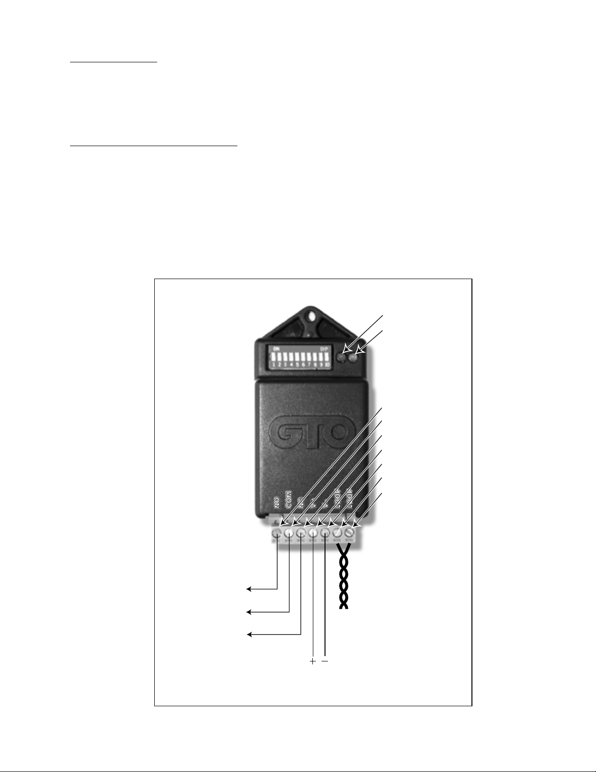
2) LED INDICATORS:
Relay output:
Normally Open
Relay output:
Common
Relay output:
Normally Close
Po
wer supply input:
8-26 Vac/dc
Loop: wire use for loop
should be continuous with
no splice. Wire pair leaving
the loop should be twisted.
DIP SWITCHS
DIP 1: PRESENCE TIMER
DIP 2: SAFE/SECURE
DIP 3: ENTER/LEAVE
DIP 4: CONT/PULSE
DIP 5: INST/DELAY
DIP 6: SENS 0
DIP 7: SENS 1
DIP 8: SENS 2
DIP 9: FREQ 0
DIP 10: FREQ 1
LED LIGHTS
LED RED: POWER
LED GRN: DETECT
NO
COMNCV+V–LOOP
LOOP
TERMINALS
TB1-1: NO
TB1-2: COM
TB1-3: NC
TB1-4: Power in +
TB1-5: Power in –
TB1-6: LOOP
TB1-7: LOOP
a) RED LED: The red LED blinks when power is present.
b) GREEN LED: The green LED blinks when detection occurs.
NOTE: Both LEDs blink when fault is detected at the loop.
3) TERMINAL BLOCK (PLUGGABLE):
a) OUTPUT RELAY: Relay is ‘dry-contact’ output.
i) TB1-1: Normally open side of output relay.
ii) TB1-2: Common side of output relay.
iii) TB1-3: Normally closed side of output relay.
b) POWER SUPPLY INPUT:
i) TB1-4: 8-26 Vac/Vdc positive input.
ii) TB1-5: 8-26 Vac/Vdc negative input.
Page 4

2“
Sealant
Backer Rod every
2 (two) feet.
Loop Wire / 3 turn
s
1/4” Saw Slot
Pavement Surface
SAW SLOT CROSS SECTION
Loop
Perimeter
6’ to 12’
13’ to 20’
21’ to 60’
61’ to 240’
240’ & Up
# of
Turns
6
5
4
3
2
Loop wires must be twisted together - 6 twists per
foot from the end of the saw slot to the detector.
Loop Installation Guidelines
The typical sensing height is 2/3 of the shortest leg of a loop (in feet). Therefore a 4’ x 8’ loop typically
has a detection range of 2.6’.
The inductance of a conventional four-sided loop can be estimated using the formula:
L = P x (T2 + T) / 4 Where L = Loop Inductance in microHenries
P = Loop Perimeter in feet
T = Number of turns of wire in saw slot
Therefore a 4’ x 8’ loop with 3 turns would be:
L + (4 + 8 + 4 + 8) x (32 + 3) / 4
L = 24 x (9 + 3) / 4
L = (24 x 12) / 4
L = 24 x 3
L = 72 microHeneries
NOTE: Loop feeder cable typically
adds 0.22 microHeneries of inductance
per foot of cable.
The following are suggested guidelines for
loop installation:
1. Make sure the pavement surface in the
area that the loops are to be installed is
dry and free of debris.
2. Design the loop geometry considering the
area of detection, the type of vehicles to
be detected and the distance between the
loop and the loop dectector.
3. The outline of the loop(s) should be
marked on the pavement in such a way
that the lines can be followed easily by
the saw operator and not be erased by the
water feed from the saw.
Page 5

4. When the outline of the loop and the lead-in has been marked the pavement can be cut. The
saw cut should be approximately 2.0 inches deep and 0.25 inches wide. All 90 degree corners
should be chamfered so that the course of the loop wire does not change direction sharply but
rather at shallow angles of 45 degrees or less. The saw slot should be cleaned out and allowed
to dry.
5. Loop wire is typically 14, 16, 18, or 20 AWG with cross-linked polyethylene insulation, rated
for direct burial. Since moisture can cause significant changes in the dielectric constant of
the insulation, which results in excessive loop (frequency) drift, choose an insulation which
is most impervious to moisture. PVC, TFFN, THHN and THHN-THWN should be avoided
since they tend to absorb moisture and crack easily. XLPE (cross-linked polyethylene) is very
resistant to moisture absorption and provides good abrasion resistance.
6. If long lead-ins are required, it is suggested that the loop cable be spliced onto shielded, pretwisted, lead-in wire (IMSA specification 50-2 is recommended) at a convenient pull box
location close to the loop. The shield may be connected to earth ground at the cabinet end but
should then be insulated and isolated from earth ground at the loop end.
7. Start laying the loop wire from the termination of the lead-in out towards the loop, continue
around the loop for the number of turns required and finally return to the lead-in termination.
Leave the lead-in wire out of the slot so that it may be twisted together before being laid in the
slot. Lead-ins should be twisted with a minimum of 4 to 6 twist per foot to prevent any separation of the lead-in wires.
8. Make sure that the loop wire is pushed fully to the bottom of the saw slot. The wire must be
held firmly in the bottom of the slot using a plastic foam material called “backer rod”, before
applying loop sealent.
9. Many different types of loop sealant are now available. Single part types are the easiest to apply since no mixing is required, but they also tend to be more expensive in terms of linear feet
of saw slot filled. When applying the sealant, make sure that it is able to sink to the bottom
of the slot and completely encase the loop wire. The wire should not be able to move when
the sealant is set. Ensure that there is enough sealant to completely fill the slot; if possible
the sealant should protrude slightly above the surface of the pavement so that small rocks or
other debris cannot collect in the slot. The sealant manufacturer’s instructions concerning cure
time should be noted - especially when determining the length of time to wait before allowing
vehicles to cross the loop area.
10. It is very important that any splices be soldered and each splice point be protected with a
moisture proof seal. Failure to do so will result in system problems, if not imediately then
sometime in the near future.
Page 6

Wiring the Loop Detector to GTO Systems
Wires from relay output
on detector
STALL FORCE
M
I
N
M
A
X
GRN
BLK
RED
RECEIVER
COM COM
CYCLE
CLOSE
SAFETY
EXIT
OPEN
SHADOW
LOOP
CLOSE
EDGE
OPEN
EDGE
J11
J8
J12
Wires from relay output
on detector
RECEIVER
COM COM
CYCLE
CLOSE
SAFETY
EXIT/
OPEN
SHADOW
LOOP
CLOSE
EDGE
OPEN
EDGE
BLKGRN RED
STALL FORCE
M
I
N
M
A
X
Wires from relay output
on detector
STALL FORCE
M
I
N
M
A
X
GRN
BLK
RED
RECEIVER
COM COM
CYCLE
CLOSE
SAFETY
EXIT
OPEN
SHADOW
LOOP
CLOSE
EDGE
OPEN
EDGE
J11
J8
J12
Wires from relay output
on detector
RECEIVER
COM COM
CYCLE
CLOSE
SAFETY
EXIT/
OPEN
SHADOW
LOOP
CLOSE
EDGE
OPEN
EDGE
BLKGRN RED
STALL FORCE
M
I
N
M
A
X
ON
ALARM ACCESSORY RCVR
SEQ1
SEQ2
LEARN
BLU
ORG
WHT
GRN
R B G
Wires from relay
output on detector
Always make sure the power switch to the operator is turned off before connecting accessory device
wiring to the terminal blocks. Unplugging the transformer does not turn power to the operator OFF.
Wiring the detector as a Shadow Loop
PRO-SW3000 & PRO-SW4000
Connect one of the relay output wires
from the detector to the COMMON
(COM) terminal and the other to the
SHADOW LOOP terminal.
Mighty Mule 500 & 502
Connect one of the relay output wires
from the detector to the COMMON
(COM) terminal and the other to the
SHADOW LOOP terminal.
Wiring the detector as a Safety Loop
PRO-SW3000 & PRO-SW4000
Connect one of the relay output wires
from the detector to the COMMON
(COM) terminal and the other to the
SAFETY terminal.
Mighty Mule 500 & 502
Connect one of the relay output wires
from the detector to the COMMON
(COM) terminal and the other to the
SAFETY terminal.
PRO-SL1000 & PRO-SL2000
Connect one of the relay output wires
from the detector to the GREEN
(GRN) terminal and the other to the
ORANGE (ORG) terminal.
Page 7

Wiring the detector as a Free Exit Loop
ON
ALARM ACCESSORY RCVR
SEQ1
SEQ2
LEARN
BLU
ORG
WHT
GRN
R B G
Wires from relay
output on detector
Wires from relay output
on detector
STALL FORCE
M
I
N
M
A
X
GRN
BLK
RED
RECEIVER
COM COM
CYCLE
CLOSE
SAFETY
EXIT
OPEN
SHADO
W
LOOP
CLOSE
EDGE
OPEN
EDGE
J11
J8
J12
Wires from relay output
on detector
RECEIVER
COM COM
CYCLE
CLOSE
SAFETY
EXIT/
OPEN
SHADOW
LOOP
CLOSE
EDGE
OPEN
EDGE
BLKGRN RED
STALL FORCE
M
I
N
M
A
X
PRO-SW3000 & PRO-SW4000
Connect one of the relay output wires
from the detector to the COMMON
(COM) terminal and the other to the
EXIT OPEN terminal.
Mighty Mule 500 & 502
Connect one of the relay output wires
from the detector to the COMMON
(COM) terminal and the other to the
EXIT OPEN terminal.
PRO-SL1000 & PRO-SL2000
Connect one of the relay output wires
from the detector to the GREEN
(GRN) terminal and the other to the
BLUE (BLU) terminal.
Page 8
Conversion Chart
Converting Metric Units to English Equivalents
When You Know Multiply By To Find Symbol
centimeters 0.3937 inches in. (or “)
meters 3.2808 feet ft. (or ‘)
kilograms 2.2046 pounds lb. (or #)
Converting English Units to Metric Equivalents
When You Know Multiply By To Find Symbol
inches 2.5400 centimeters cm
feet 0.3048 meters m
pounds 0.4535 kilograms kg
Converting Temperature
deg. Celsius (ºC x 1.8) + 32 deg. Fahrenheit ºF
deg. Fahrenheit (ºF-32) ÷ 1.8 deg. Celsius ºC
This product and any accessory you purchase should only be installed on a gate
operator that meets the current safety standard, UL325, latest edition. If you have
a gate operator that is not listed with the current standard please contact the GTO
sales department for consultation on a gate operator that can meet your specific
needs.
GTO Limited One Year Warranty:
GTO, Inc., gate operators and accessories are warranted by the manufacturer against defects in materials and manufacturer workmanship
for a period of one (1) year from date of purchase, provided the recommended installation procedures have been followed.
In the case of product failure due to defective material or manufacturer workmanship within the one (1) year warranty period, the product
will be repaired or replaced (at the manufacturer’s option) at no charge to the customer, if returned freight prepaid to GTO, Inc., 3121
Hartsfield Road, Tallahassee, Florida, USA 32303. IMPORTANT: Call (850) 575-4144 or Fax (850) 575-8950 for a Return Goods
Authorization (RGA) number before returning accessory to factory. Products received at the factory without an RGA number will not
be accepted. Replacement or repaired parts are covered by this warranty for the remainder of the one (1) year warranty period or six (6)
months, whichever is greater. GTO, Inc. will pay the shipping charges (equal to United Parcel Service GROUND rate) for return to the
owner of items repaired under warranty.
The manufacturer will not be responsible for any charges or damages incurred in the removal of the defective parts for repair, or for the
reinstallation of those parts after repair. This warranty shall be considered void if damage to the product(s) was due to improper installation
or use, connection to an improper power source, or if damage was caused by lightning, wind, fire, flood, insects or other natural agent.
After the one (1) year warranty period, GTO, Inc. will make any necessary repairs for a nominal fee. Call GTO at (800) 543-1236 for
more information. This warranty gives you specific legal rights, and you may also have other rights which may vary from state to state.
This warranty is in lieu of all other warranties, expressed or implied. NOTE: Verification of the warranty period requires copies of
receipts or other proof of purchase. Please retain these records.
If you have any questions call Technical Support at... (800) 543-1236
or GTO/PRO Sales at... (800) 543-4283
 Loading...