

Page 1
x2
DELAY TIMER
0 6
0
1
1
8
9
10
11
14
12
13
15
2
2
3
3
4
4
5
5
6
6
7
7
GLUE
16
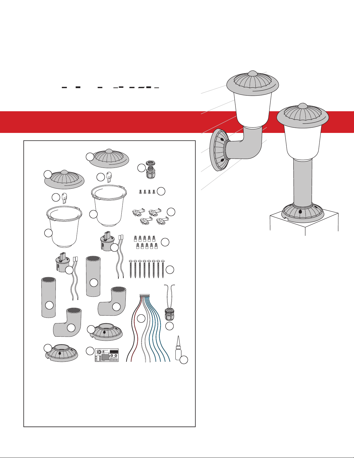
2. 4 Watt Light Bulb (2)
3. Light Lens (2)
4. Light Socket & wires (2)
5. Top Mount Lens Support (2)
6. Face Mount Lens Support (2)
8. Strain Relief Nut (1)
9. Lens Hood Screws (4)
Parts Included:
Digital Controller:
Controls lights to
conserve battery life. Built-in adjustable
time-on control, allows you to adjust the
light timer from 0-120 seconds.
Connects to existing
gate opener power system with no addi-
tional wiring or power source required.
Only allows activation from
dusk-to-dawn for energy conservation
preventing lights from coming on when
not necessary.
Allows you to clearly
Professional land-
resistant to prevent discoloration of the
lenses.
Enhances the appearance of
your entrance and drive.
Post and column mount ap-
plication hardware included.
with Digital Controller
Face Mount
Post Mount
©2005 GTO, Inc.
rev - 04/07/05
IMPORTANT:
16 gauge, multi-stranded, direct burial, low voltage wire (RB509) is required to connect the
lights to the digital control board (see diagram on page 1). Small sections of the same wire will also be required
for connecting light kit control board to gate operator control board and power source. Please read manual to
determine how much wire you will need.
Page 2

Thank you...
for purchasing the Digital Controlled Gate Opener Light Kit. GTO, Inc., has been designing and manufac-
turing reliable, high quality products since 1987. Our corporate headquarters and state of the art manu-
facturing facility is located in Tallahassee, Florida. One of our highest priorities is to provide outstanding
technical service to our customers. Therefore, if you have any questions or require any technical assis-
tance, please call our toll free line 800-543-1236 or 850-575-4144 and ask to speak to one of our techni-
cians.
The Digital Controlled Gate Opener Light Kit you have purchased is designed with some of the most
controller and controls the activation and duration of the low voltage lights at the gate. The Photo Sensor
only allows the light to be activated during low light or dark periods of the day for energy conservation.
The lights come on when the gate operator is activated and will remain on from 0 to 120 seconds from the
time the gate closed.
Prior to installing your Light Kit, please read this manual thoroughly. There are important safety recom-
mendations of which you should be aware. This product, and any accessory you purchase, should only be
installed on a gate opener that meets the current safety standard (UL325). If you have a gate opener that
is not listed with the current standards, please contact the GTO sales department at 800-543-4283 or 850-
Joe Kelley, President of GTO, Inc.
Before You Start
.....................................................................................................................
page 1
How the Digital Light Kit Works
....................................................................................
page 1
Installation Overview
.....................................................................................................
page 1
Installing the Lights
...............................................................................................................
page 2
Installing Lights on the Face of the Gate Post
................................................................
page 2
Installing Lights on Top of the Gate Post
........................................................................
page 3
Installing the Photocell and Control Board
...........................................................................
page 4
Installing the photocell and low voltage wire strain relief
.............................................
page 4
Wiring the Light Kit
..............................................................................................................
page 4
Connecting Light Kit to Mighty Mule FM500/502, GTO/PRO SW2500,
SW3000, and SW4000 Gate Openers
.............................................................................
page 5
Connecting Light Kit to Mighty Mule FM700, GTO/PRO SW1000, SW2000,
SL1000 and SL2000 SINGLE Gate Openers
................................................................
page 6
Connecting Light Kit to Mighty Mule FM702, GTO/PRO SW1000/1200,
SW2000/2200, SL1000/1200 and SL2000/2200 DUAL Gate Openers
.......................
page 7
Connecting Light Kit to Mighty Mule 350 and GTO/PRO-SW1500 Openers
...............
page 8
Programming the Light Kit
...................................................................................................
page 9
Testing the Light Kit
.......................................................................................................
page 9
Trouble Shooting and Technical Specifi cations
....................................................................
page 9
Metric Conversion Chart & Warranty
....................................................................................
page 10
Page 3
The Digital Light Kit is designed to work in conjunction with GTO automatic gate openers to illuminate
the entry way while the gate is being opened and closed during night time hours. The low voltage lights
photo cell allows the lights to only come on at night which conserves energy and battery power, making
the Digital Light Kit ideal for low voltage DC powered automatic gate openers.
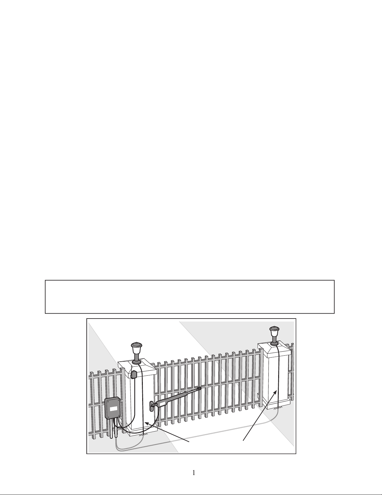
The lights can be assembled to mount on the face of your gate posts or on top of the posts. Once you
determine where you want to mount the lights, you will assemble the lights and attach them to the gate
post. Low voltage wire (RB509) will be needed to connect the lights mounted on the gate post to the
light kit control board. GTO recommends that all wires be run in PVC conduit.
The light kit control board is normally mounted inside the gate opener’s control box close to the gate
opener’s control board. If it will not fi t in the gate opener’s control box or your gate opener doesn’t
have a control box, a weatherproof junction box must be used to house the light kit control board and
low voltage wire (RB509) must be used to connect the light kit control board to the gate opener control
board.
The photocell will be mounted in the bottom of either the gate opener’s control box or the weatherproof
junction box, depending on where you installed the light kit control board.
After everything is installed, you will program the light kit control board for the length of time you wish
the lights to remain on after the gate is opened.
IMPORTANT:
16 gauge, multi-stranded, direct burial, low voltage wire (RB509) is required
to connect the lights to the digital control board (see diagram below) and in some cases small
Low Voltage Wire
Page 4
2
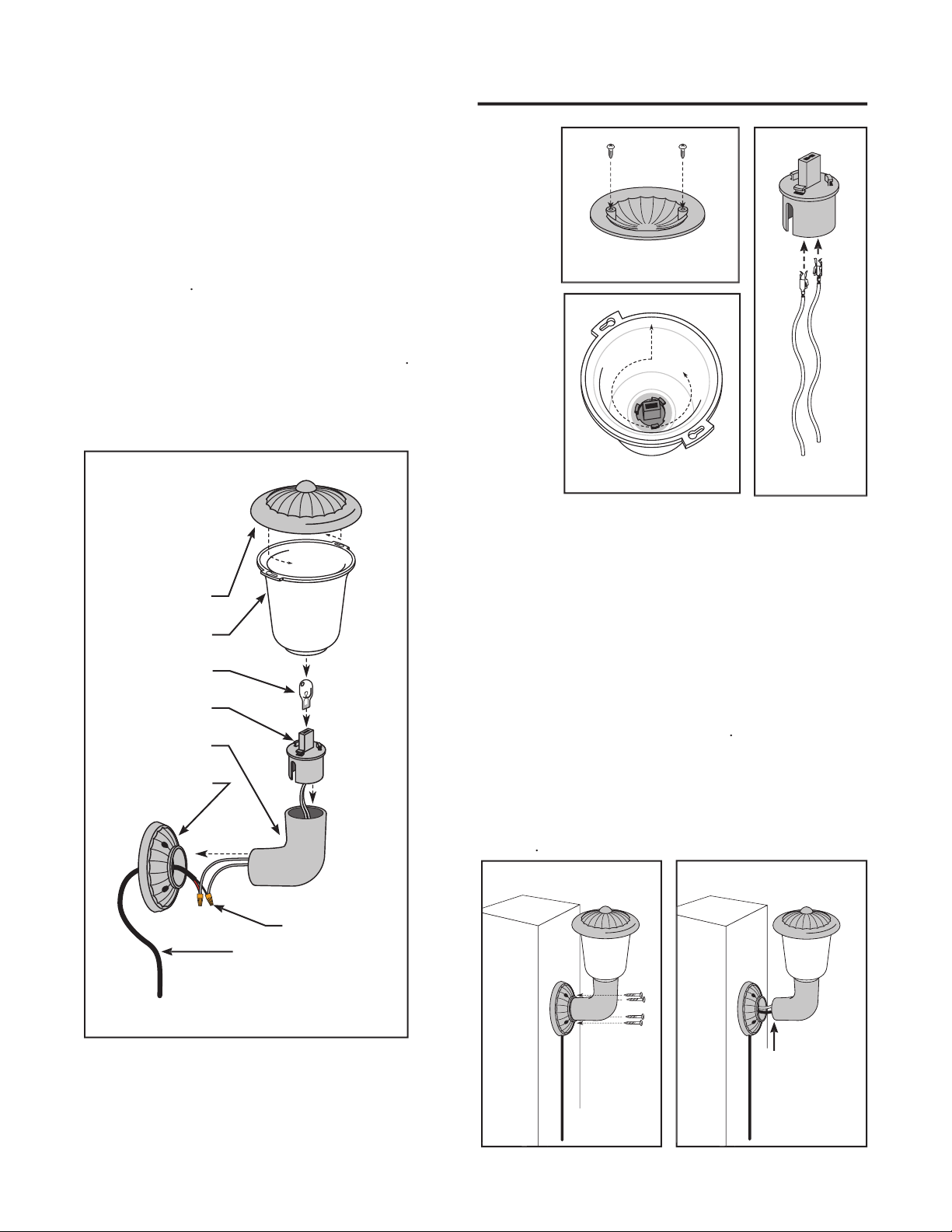
Figure 4
Lens Hood
Lens
4 Watt Light
Light Socket
Lens Support
Mounting Plate
Low Voltage Wire
Figure 5
Figure 1
Installing lights on the face of the gate post:
Figure 1
lock into place on top of lens.
2. Install wires into the light bulb socket by simply pressing a brass
connector into each side of the socket until it snaps into place.
Figure 2
Line up the slots on the socket with the notches in the lens. Insert
the scoket into the lens. Firmly grasp the socket, push and twist
until it snaps into place as shown in
Figure 3
4. Assemble the rest of the light using the angled lens support as
Figure 4
Figure 2
Figure 3
5. Determine where the low voltage wire will be run.
Connect to the lights using the wire nuts provided
before mounting the fi xtures. The notches in the
mounting plates are openings for running the low
voltage wire. Be sure it is facing the direction the
wire will enter.
hardware my be required depending on the type of
gate posts you have. See
Figure 5
7. When you are satisfi ed with the placement of the
fi xtures, glue the lens support pieces using a small
glue off the outside of the support pieces. See
Fig-
Figure 6
amount of glue
to secure lens
support as-
sembly
Page 5

Installing lights on top of the gate post:
hood as shown in
Figure 7
2. Install wires into the light bulb socket by simply press-
ing a brass connector into each side of the socket until it
Figure8
Line up the slots on the socket with the notches in the
lens. Insert the scoket into the lens. Firmly grasp the
in
Figure 9
4. Assemble the rest of the light using the angled lens sup-
port as shown in
Figure 10
amount of glue
to secure lens
support as-
sembly
Figure 12
Figure 11
Figure
Lens Hood
Lens
4 Watt Light
Light Socket
Lens Support
Mounting Plate
Low Voltage Wire
5. Determine where the low voltage wire will be run. Con-
nect to the lights using the wire nuts provided before
mounting the fi xtures. The notches in the mounting plates
is facing the direction the wire will enter.
bled fi xtures to the gate posts. Additional hardware my
be required depending on the type of gate posts you have.
Figure 11
7. When you are satisfi ed with the placement of the fi xtures,
glue the lens support pieces using a small amount of glue
the support pieces. See
Figure12
Figure 7
Figure 8
Figure 9
Page 6

4
Figure 14
Low Voltage
Lights
PVC Conduit
Installing the photocell and low voltage wire strain relief:
operator control box or a weatherproof junction box. If knockouts
Figure 13
2. In another knockout or 5/8” hole, install the strain relief provided.
Run the low voltage wire from the lights through the strain relief
into the box. Secure by tightening the strain relief nut until the wire
is snug. Always run wire from the ground to the box in PVC conduit
to protect it from grazing animals and weed eaters. See
Figure 14
Figure 13
Photocell
Wiring the Light Kit
Installing the Photocell:
Place the Light Kit control board in the gate operator control box or a
weatherproof junction box. Connect the Light Kit control board using
Figure 15
and the Wiring Diagrams on the following pages.
Figure 15
2. Connect the two RED wires from the lights to one of the Light Kit
control board terminals. Connect the two BLACK wires from the
lights to another Light Kit control board terminal.
IMPORTANT: Only use the two terminals shown in
Figure 15
to con-
nect the wires from the lights.
NOTE:
Included in the light kit
wire to the middle of another.
With wires in place, fold locking
tab over and press until it locks
in place. Make sure the locks are
clamped securly to the wires. Use
pliers if neccessary. See
Figure 16
Figure 16
x2
DELAY TIMER
0 6
0
Low Voltage
Lights
RED Wire
BLACK Wire
BLUE Wires
Potentiometer for Adjusting
the Light Duration Delay
AY
TIME
0 6
AY
TIME
AY TIMEAY
Figure 15
Page 7

and SW4000 Gate Openers:
and
a short section of 16 gauge low voltage wire (not
provided) to the RLY-COM (Relay Common) terminal on the gate opener control board. Connect the other end
of the short section of wire to the RED gate opener battery lead using the wire splicing locks provided.
See
diagram below and Figure 16
2. Connect the BLACK wire from the Light Kit control board to the COM (COMMON) terminal on the gate
operator control board.
See diagram below
voltage wire (no provided) using a wire nut (provided). Connect the other end of the short section of wire to the
NO (Normally Open) terminal RELAY OUT terminal on the gate opener control board.
See diagram below
4. Connect the WHITE wires from the photocell to the WHITE wires from the Light Kit control board using the
wire nuts provided.
See diagram below
x2
DELAY TIMER
0 6
0
SWITCH
18 VAC SOLAR RELAY OUT
~ ~ - +
NC NORLY-COM
SLAVE INPUTS
GRN WHT BLUE BRN ORG RED BLK
MASTER INPUTS
GRN WHT BLUE BRN ORG RED BLK
GRN BLK RED
RECEIVER
COM COM
CYCLE
CLOSE
SAFETY
EXIT
OPEN
SHADOW
LOOP
CLOSE
EDGE
OPEN
EDGE
STALL FORCE
M
I
N
M
A
X
J11
J8J5J13J21J6J9J2J1
J12
Lights
Photocell
Light Kit
BLACK Wire
to
Light Kit Wire and short sec-
tion of 16 gauge low voltage wire to
RLY-COM
on
RELAY OUT
Mighty Mule 500/502, GTO/PRO SW2500, SW3000 and SW4000 Control Boards
BLUE
Wires
Wires
Short section of 16 gauge low
voltage wire (any color) --
from
RLY-COM
terminal to
RED
battery lead.
Short section of 16 gauge
low voltage wire (any color)
Page 8

6
and SL2000 SINGLE Gate Openers:
provided) using a wire nut provided. Connect the other end of the JUMPER wire to the RED gate opener bat-
tery lead using the wire splicing locks provided.
See diagram below and Figure 16
2. Connect the BLACK wire from the Light Kit control board to the GRN ACCESSORY terminal on the gate
operator control board.
See diagram below
BLUE wires to the BLK OPERATOR terminal on the gate opener control board.
See diagram below
4. Connect the WHITE wires from the photocell to the WHITE wires from the Light Kit control board using the
wire nuts provided.
See diagram below
ON
SECOND OPERATORFIRST OPERATORPOWER IN ALARM ACCESSORY RCVR
SEQ1
SEQ2
LEARN
18VAC SOLAR
~ ~ – +
RED
BL
K
ORG
BL
U
GR
N
CLS ED
G
OPN ED
G
RE
D
BL
K
BL
U
OR
G
OR
G
BL
U
WHT
GRN
GR
N
CLS ED
G
OPN ED
G
R B G
x2
DELAY TIMER
0 6
0
Lights
Photocell
BLACK Wire
to
Accessory
Mighty Mule FM700, GTO/PRO SW1000, SW2000, SL1000 and SL2000 SINGLE Gate Control Boards
BLUE
Wires
Wires
CESSORY
BLUE wires to RED and
BLACK Operator Termi-
nals - two each in single
gate application.
Short section of 16 gauge
low voltage wire (any color)
connecting
Light Kit
wire to
battery lead.
Light Kit
Page 9

7
provided) using a wire nut provided. Connect the other end of the short section of wire to the RED gate opener
battery lead using the wire splicing locks provided.
See diagram below and Figure 16
2. Connect the BLACK wire from the Light Kit control board to the GRN ACCESSORY terminal on the gate
operator control board.
See diagram below
BLUE wire to the BLK terminal on the gate opener control board. Connect one BLUE wire from the Light Kit
control board to the SECOND OPERATOR RED terminal and one BLUE wire to the BLK terminal on the gate
opener control board.
See diagram below
4. Connect the WHITE wires from the photocell to the WHITE wires from the Control Board Plug using the wire
nuts provided.
See diagram below
ON
SECOND OPERATORFIRST OPERATORPOWER IN ALARM ACCESSORY RCVR
SEQ1
SEQ2
LEARN
18VAC SOLAR
~ ~ – +
RED
BL
K
ORG
BL
U
GR
N
CLS ED
G
OPN ED
G
RE
D
BL
K
BL
U
OR
G
OR
G
BL
U
WHT
GRN
GR
N
CLS ED
G
OPN ED
G
R B G
x2
DELAY TIMER
0 6
0
Lights
Photocell
BLACK Wire
to
Accessory
Mighty Mule FM702, GTO/PRO SW1000, SW2000, SL1000 and SL2000 DUAL Gate Control Boards
BLUE
Wires
Wires
CESSORY
BLUE wires to RED and
BLACK Operator Termi-
nals - one each in dual
gate application.
Short section of 16 gauge
low voltage wire (any color)
connecting
Light Kit
wire to
RED
battery lead.
Light Kit
Page 10

8
ON/OFF
12 Volt DC
AUTOMOTIVE
or MARINE
TYPE BATTERY
x2
DELAY TIMER
0 6
0
NOTE:
When the Light Kit is used with the Mighty Mule 350 or the GTO/PRO-SW1500, a weatherproof junc-
tion box (not included) must be used to house the Light Kit control board and Photocell. Weatherproof junction
boxes can be found at your local hardware or electrical supply stores.
BLACK
operator
power wire
Lights
Photocell
Light Kit Control Board
BLACK
Light Kit
wire to
Negative
Battery Terminal
Mighty Mule FM350 and GTO/PRO SW2500 Gate Opener Control Boards
BLUE
Wires connect to
opener power wires
RED
Light Kit wire
to
Positive
Battery
BLUE
Light Kit wires
to
and
BLACK
opener power wires
Wires connect to
Photocell
x2
operator
power wire
RED
and
BLACK
Light Kit
wires connect to battery
wire long enough to run from the junction box to the gate opener battery. Connect the RED wire to the POSI-
TIVE battery terminal and the BLACK wire to the NEGATIVE battery terminal.
See diagram below
2. Connect the BLUE Light Kit wires to two sections of 16 gauge low voltage wire (two BLUE wires to each
the gate opener control board (one to the RED wire and one to the BLACK wire), using the wire splicing locks
See diagram below and Figure 16
4. Connect the WHITE wires from the photocell to the WHITE wires from the Control Board Plug using the wire
nuts provided.
See diagram below
Page 11

9
the jumper (X2) on the control board. Using a small
desire between 0-60 seconds. See
Figure 14
Adjusting the Time-On Delay:
The Light’s Time-On can be set to leave the lights on from 0-120 second from the time the gate stops.
x2
DELAY TIMER
0 6
0
Potentiometer set
between 0-60
seconds
Figure 14
Jumper X2 is
disconnected
x2
DELAY TIMER
0 6
0
Figure 15
Potentiometer set
between 60-120
seconds
Jumper X2 is
connected
2. To set the Time-On from 0-120 seconds connect the
jumper (X2) on the control board. Using a small screw-
driver, turn the potentiometer to the time you desire
between 0-120 seconds. See
Figure 15
In order to test the light kit in the day light, place a piece of black electrician’s tape over the photocell lens then
wait for 2 minutes. Activate the gate operator by pressing the gate operator’s transmitter button or another activa-
tion device.
The lights should come on when the gate is activated and go off at the time delay you have set.
If any of these actions did not occur, please call GTO Technical Service at 1-800-543-4283 for additional informa-
tion.
When everything is working correctly, replace all connection covers, remove the electrician’s tape and your done.
Features and Technical Specifi cations:
vate, conserving battery power for the operator.
The GTO, Inc. Technical Service Department is open
Monday – Friday 8:00 A.M. – 5:00 P.M. (Eastern Time)
For technical service Call toll free: 1-800-543-1236
For sales call toll free: 1-800-543-GATE (4283)
Page 12

This product and any accessory you purchase should only be installed on a gate
opener that meets the current safety standard, UL325, 4th Edition. If you have a
gate opener that is not listed with the current standard please contact the GTO sales
department for consultation on a gate opener that can meet your specifi c needs.
www.gtoinc.com
When You Know Multiply By To Find Symbol
centimeters 0.3937 inches in. (or “)
meters 3.2808 feet ft. (or ‘)
kilograms 2.2046 pounds lb. (or #)
When You Know Multiply By To Find Symbol
inches 2.5400 centimeters cm
feet 0.3048 meters m
pounds 0.4535 kilograms kg
deg. Celsius (ºC x 1.8) + 32 deg. Fahrenheit ºF
deg. Fahrenheit (ºF-32) ÷ 1.8 deg. Celsius ºC
Limited One Year Warranty
GTO, Inc. gate opener accessories are warranted by the manufacturer against defects in workmanship for a period of one (1) year from the date of
purchase, provided recommended installation procedures have been followed.
In the case of product failure due to defective material or manufacturer workmanship within the one (1) year warranty period, the accessory will
be repaired or replaced (at the manufacturer’s option) at no charge to the customer, if returned freight prepaid to GTO, Inc., 3121 Hartsfi eld Rd.,
Tallahassee, FL 32303. IMPORTANT: Call 850/575-4144 or fax 850/575-8950 for a Return Goods Authorization (RGA) number before returning
goods to factory. Products received at the factory without an RGA will not be accepted. Replacement or repaired parts are covered by this warranty
for the remainder of the one (1) year warranty period. GTO, Inc. will pay the shipping charges for return to the owner of items repaired.
The manufacturer will not be responsible for any charges or damages incurred in the removal of the defective parts for repair, or for the reinstallation
of those parts after repair. This warranty shall be considered void if damage to the product(s) was due to improper installation or use, connection to
an improper power source, tampering, or if damage was caused by lightning, wind, fi re, fl ood, insects, or other natural agent.
After the one (1) year warranty period, GTO Inc. or one of its authorized service centers will make any necessary repairs for a nominal fee. Call GTO
at 850/575-4144 for more information. This warranty gives you specifi c legal rights, and you may also have other rights which may vary from state
to state. This warranty is in lieu of all other warranties, expressed or implied. NOTE: Verifi cation of the warranty period requires copies of receipts
or other proof of purchase. Please retain those records.
The contents of all material available on this installation manual are copyrighted by GTO, Inc. (“GTO”), unless otherwise indicated. All rights are reserved by GTO, and content may not be
reproduced, downloaded, disseminated, published, or transferred in any form or by any means, except with the prior, written permission of GTO. Any reprinting of GTO publications is by
permission only. Copyright infringement is a violation of federal law.
GTO®, GTO/PRO®, Mighty Mule® are registered trademarks of GTO, Inc. Professional Access Systems™ is a trademark of GTO, Inc. and are the exclusive property of GTO, Inc. (“GTO”).
All rights are reserved by GTO, and these marks may not be used, in any for without the prior, written permission of GTO.
 Loading...