

Page 1

Installation Manual for the
®
DC-SERIES
1-800-543-GATE (4283) • www.gtopro.com
®
DC-SERIES
WARNING
!
MOVING GATE
Can Cause Injury or Death
SINGLE Gate Operator System
FOR PROFESSIONAL INSTALLATION ONLY!
WARNING!
This equipment is similar to other gate or door equipment and meets or exceeds
Underwriters Laboratory Standard 325 (UL 325). However, gate equipment has
hazards associated with its use and therefore by installing this product the installer
and user accept full responsibility for following and noting the installation and
safety instructions. Failure to follow installation and safety instructions can result
in hazards developing due to improper assembly. You agree to properly install this
product and that if you fail to do so GTO, Inc. shall in no event be liable for direct,
indirect, incidental, special or consequential damages or loss of profits whether
based in contract tort or any other legal theory during the course of the warranty
or at any time thereafter. The installer and/or user agree to assume responsibility
for all liability and use of this product releasing GTO, Inc. from any and all
liability. If you are not in agreement with this disclaimer or do not feel capable
of properly following all installation and safety instructions you may return this
product for full replacement value.
READ ALL INSTRUCTIONS CAREFULLY AND COMPLETELY before
attempting to install and use this automatic gate operator. This gate operator
produces a high level of force. Stay clear of the unit while it is operating and
exercise caution at all times.
All automatic gate operators are intended for use on vehicular gates only.
This product meets and exceeds the requirements of UL 325, the standard which regulates gate operator safety,
as established and made effective March 1, 2000, by Underwriters Laboratories Inc.
Telephone GTO Sales: 1-800-543-GATE (4283) or (850) 575-0176 • Fax (850) 575-8912
or GTO Technical Service: 1-800-543-1236 or (850) 575-4144 • Fax (850)575-8950
3121 Hartsfield Road • Tallahassee, Florida, USA 32303
www.gtopro.com
©
2002 GTO, Inc.
R3000 INST
rev - 02/21/06
Page 2

The GTO/PRO® 3000 Gate Operator is intended for use with vehicular swing gates. The operator can be used in
Class I, Class II, Class III and Class IV applications.
VEHICULAR GATE OPERATOR CLASS CATEGORIES
Residential Vehicular Gate Operator-Class I: A vehicular gate operator (or system) intended for use in a home
of one-to-four single family dwelling, or a garage or parking area associated therewith.
Commercial/General Access Vehicular Gate Operator-Class II: A vehicular gate operator (or system) intended
for use in a commercial location or building such as a multifamily housing unit (five or more single family units),
hotel, garages, retail store, or other building servicing the general public.
Industrial/Limited Access Vehicular Gate Operator–Class III: A vehicular gate operator (or system) intended
for use in an industrial location or building such as a factory or loading dock area or other locations not intended to
service the general public.
Restricted Access Vehicular Gate Operator–Class IV: A vehicular gate operator (or system) intended for use
in a guarded industrial location or building such as an airport security area or other restricted access locations not
servicing the general public, in which unauthorized access is prevented via supervision by security personnel.
Conversion Chart
Converting Metric Units to English Equivalents
When You Know Multiply By To Find Symbol
centimeters 0.3937 inches in. (or ")
meters 3.2808 feet ft. (or ')
kilograms 2.2046 pounds lb. (or #)
Converting English Units to Metric Equivalents
When You Know Multiply By To Find Symbol
inches 2.5400 centimeters cm
feet 0.3048 meters m
pounds 0.4535 kilograms kg
Converting Temperature
deg. Celsius (ºC x 1.8) + 32 deg. Fahrenheit ºF
deg. Fahrenheit (ºF-32) ÷ 1.8 deg. Celsius ºC
FOR YOUR RECORDS
Please record the product serial number (located on the control box cover), and the date
and place of purchase in the spaces provided below. Refer to this information when
calling GTO for service or assistance with your automatic gate operator.
Serial Number ____________________ Date of Purchase ____________________
Place of Purchase ____________________
Remember to keep all receipts for proof of purchase.
Page 3

Table of Contents
Gate Operator Class Categories ------------------------------------------------------------inside cover
Units and Standards Conversion Chart ---------------------------------------------------inside cover
PLEASE READ THIS FIRST! --------------------------------------------------page iii
Important Safety Instructions --------------------------------------------------page 1
KEEP THESE INSTRUCTIONS FOR FUTURE REFERENCE
Disconnecting the Operator ----------------------------------------------------------- page 1
Important Safety Instructions for the Consumer ------------------------------------ page 2
Secondary Means of Protection Against Entrapment ------------------------------ page 5
Required Safety Precautions for Gates -----------------------------------------------page 6
Warning Signs and Labels -------------------------------------------------------------page 7
Installation --------------------------------------------------------------------------page 8
Parts List ---------------------------------------------------------------------------------page 8
Technical Specifications -------------------------------------------------------------page 10
Installation Overview ---------------------------------------------------------------- page 11
Installation of the Mounting Hardware ----------------------------------------------page 12
Mounting the Operator ----------------------------------------------------------------- page 16
Installation of the Closed Position Stop ---------------------------------------------page 16
Mounting the Control Box ------------------------------------------------------------- page 17
Connecting the Power Cable --------------------------------------------------------- page 18
Powering the System --------------------------------------------------------------page 19
Solar Chart -------------------------------------------------------------------------------page 19
Connecting the Transformer -----------------------------------------------------------page 19
Control Board Settings ----------------------------------------------------------page 22
DIP Switches ----------------------------------------------------------------------------page 22
Setting the Closed Position ------------------------------------------------------------ page 23
Obstruction Sensitivity -----------------------------------------------------------------page 24
Setting Your Personal Transmitter Code -------------------------------------page 25
Installing the Receiver -----------------------------------------------------------page 26
Connecting Additional Safety Devices ----------------------------------------page 27
Connecting Accessories ----------------------------------------------------------page 29
Push to Open Installation --------------------------------------------------------page 30
Maintenance & Troubleshooting Guide --------------------------------------page 33
Repair Service ---------------------------------------------------------------------page 35
Column Installation Information ----------------------------------------------page 36
Accessory Catalog ----------------------------------------------------------------page 37
Page 4

PLEASE READ THIS FIRST!
®
DC-SERIES
Thank you for purchasing a GTO/PRO® 3000 When correctly installed and properly used, your GTO/PRO® 3000
Operator will give you many years of reliable service. Please read the following information to ensure you have
the correct system for your particular needs. This manual will enable you to properly install your GTO/PRO® 3000
Automatic Gate Operator.
The GTO/PRO® 3000 Operator is designed for installation on a pull-to-open single leaf gate (gates that open into
the property). By purchasing an accessory bracket, the GTO/PRO® 3000 Operator can accommodate a push-to-
open single leaf gate (gates that open out from the property). The gate must not exceed 16 feet in length (per leaf)
nor weigh more than 650 pounds (per leaf) (please see Technical Specifications on page 10). The GTO/PRO® 3000
Operator can be used on vinyl, aluminum, chain link, farm tube, and wrought iron gates. Use on solid (wood) gates
is not recommended. Solid surface gates have a high resistance to the wind. If the wind is strong enough, the operator
will obstruct and stop.
The GTO/PRO® 3000 Operator accommodates extra transmitters, digital keypads, solar panels, push buttons,
automatic gate locks, and other access control products. These optional accessories (see the enclosed GTO/PRO®
Accessory Catalog) are available.
The GTO/PRO® 3000 Operator features adjustable obstruction sensing. This safety feature makes the gate stop
and reverse direction within 2 seconds when it comes in contact with an obstruction. MIN is the factory setting;
meaning the gate will exert the minimum force on an obstruction before it stops and reverses direction.
The GTO/PRO® 3000 Operator also has an adjustable auto-close feature. After the gate reaches the fully open
position, it can be set to remain open up to 120 seconds before automatically closing. Pressing the transmitter button
at any time after the gate opens fully will cause it to close immediately. OFF is the factory setting; meaning the gate
will stay open until you press the transmitter (or keypad, etc.) again.
Please call GTO at (800) 543-GATE [4283] or (850) 575-0176 for more information about our GTO/PRO®
professional line of gate operators and accessories. Our Sales Department will be glad to give you the name and phone
number of a GTO/PRO® dealer near you.
BEFORE YOU BEGIN TO INSTALL YOUR AUTOMATIC GATE OPERATOR:
Read these instructions carefully and completely to become
familiar with all parts and installation steps.
You must read the installation manual for detailed instructions on
gate operator safety and proper use of the gate operator.
iii
Page 5
IMPORTANT SAFETY INSTRUCTIONS
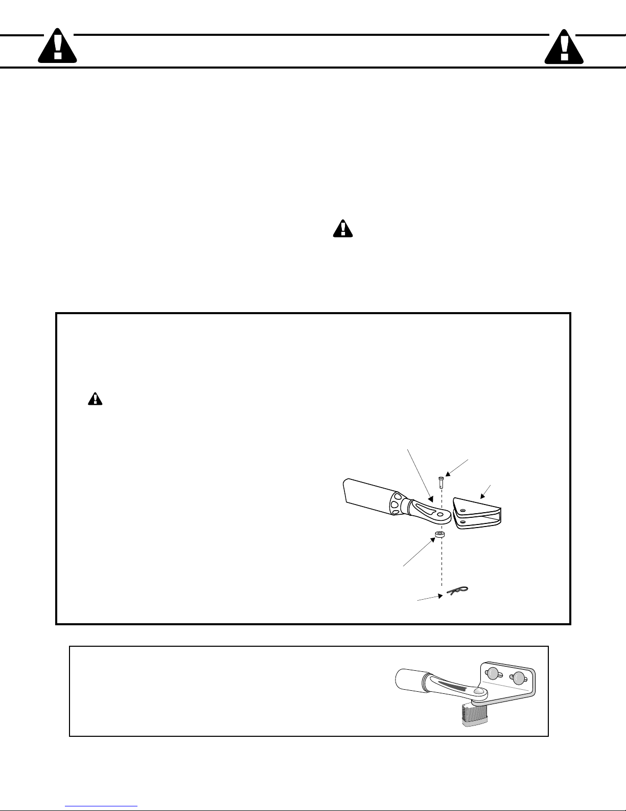
Clevis Pin
Hairpin Clip
Gate Bracket
Front Mount
Bushing
Because automatic gate operators produce high levels of force, consumers need to know the potential hazards associated with
improperly designed, installed, and maintained automated gate operator systems. Keep in mind that the gate operator is
just one component of the total gate operating system. Each component must work in unison to provide the consumer with
convenience, security, and safety.
This manual contains various safety precautions and warnings for the consumer. Because there are many possible
applications of the gate operator, the safety precautions and warnings contained in this manual cannot be completely
exhaustive in nature. They do, however, provide an overview of the safe design, installation, and use of this product.
CAREFULLY READ AND FOLLOW ALL SAFETY PRECAUTIONS, WARNINGS, AND INSTALLATION
INSTRUCTIONS TO ENSURE THE SAFE SYSTEM DESIGN, INSTALLATION, AND USE OF THIS PRODUCT.
Precautions and warnings in this manual are identified with this warning symbol. The symbol identifies conditions
that can result in damage to the operator or its components, serious injury, or death.
Because GTO automatic gate operators are only part of the total gate operating system, it is the responsibility of the
consumer to ensure that the total system is safe for its intended use.
To Manually Open and Close the
Gate, Follow the Procedure Below:
CAUTION: The gate will move freely and uncontrolled when the gate operator is
removed from the gate. ONLY disconnect the operator when the control box power
switch is OFF and the gate is NOT moving.
Disconnecting the Operator
1. Turn control box power switch OFF.
2. Remove hairpin clip, clevis pin, and bushing
from either the front or rear mounting point.
3. Remove the opener from the mount.
The gate can be opened and closed manually
when the operator is disconnected.
NOTE: Substitute a Pin Lock for the clevis pin on the front
mount of the gate operator to prevent unauthorized removal of
the operator from the gate (see Accessory Catalog).
1
Page 6

IMPORTANT SAFETY INSTRUCTIONS
Gate in the
Open Position
ZONE 2
ZONE 3
ZONE 4
ZONE 5
Driveway
ZONE 1
For The Consumer
WARNING: To reduce the risk of injury or death:
1. READ AND FOLLOW ALL INSTRUCTIONS. Failure to meet the requirements set forth in the instruction
manual could cause severe injury and/or death, for which the manufacturer cannot be held responsible.
2. When designing a system that will be entered from a highway or main thoroughfare, make sure the system is placed
far enough from the road to prevent traffic congestion.
3. The gate must be installed in a location that provides adequate clearance between it and adjacent structures when
opening and closing to reduce the risk of entrapment. Swinging gates must not open into public access areas.
4. The gate and gate operator installation must comply with any applicable local codes.
I. Before Installation
1. Verify this operator is proper for the type and size of gate, its frequency of use and the proper class rating.
2. Make sure the gate has been properly installed and swings freely in both directions. Repair or replace all worn or
damaged gate hardware prior to installation. A freely moving gate will require less force to operate and will enhance
the performance of the operator and safety devices used with the system.
3. Review the operation of the system to become familiar with its safety features. Understand how to disconnect the
operator for manual gate operation (see page 1).
4. This gate operator is intended for vehicular gates ONLY. A separate entrance or gate must be installed for
pedestrian use (see page 6).
5. Always keep people and objects away from the gate and its area of travel. NO ONE SHOULD CROSS THE
PATH OF A MOVING GATE.
6. Pay close attention to the diagram below and be aware of these areas at all times.
Entrapment
Zones for a
Pull-To-Open
Application
2
Page 7

IMPORTANT SAFETY INSTRUCTIONS
Moving Gate
Area
Driveway
10'
10'
10'
10'
NEVER INSTALL
any control device
within gray area
Entrapment Zones for a proper Pull-To-Open installation:
Zone 1 – leading edge of the gate and the fence post.
Zone 2 – between the gate and the gate post.
Zone 3 – the path of the gate.
Zone 4 – the space between the gate in the open position and any object such as a wall, fence, tree, etc.
Zone 5 – pinch points between the opener and gate or post.
II. During Installation
1. Install the gate opener on the inside of the property and fence line. DO NOT install an opener on the outside of the
gate where the public has access to it.
2. Be careful with moving parts and avoid close proximity to areas where fingers or hands could be pinched.
3. Devices such as contact sensors (safety edges) and non contact sensors (photo beams) provide additional protection
against entrapment.
4. If push buttons or key switches are installed, they should be within sight of the gate, yet located at least 10 feet from
any moving part of the gate (see diagram below). Never install any control device where a user will be tempted to
reach through the gate to activate the gate opener.
5. Do not activate your gate opener unless you can see it and can determine that its area of travel is clear of people,
pets, or other obstructions. Watch the gate through its entire movement.
6. Secure outdoor or easily accessed gate opener controls in order to prohibit unauthorized use of the gate.
Pull-To-Open
Application
3
Page 8
IMPORTANT SAFETY INSTRUCTIONS
III. After Installation
1. Attach the warning signs (included) to each side of the gate to alert the public of automatic gate operation. It is
your responsibility to post warning signs on both sides of your gate. If any of these signs or warning decals become
damaged, illegible or missing, replace them immediately. Contact GTO for free replacements.
2. The gate is automatic and could move at any time, posing a serious risk of entrapment. No one should be in contact
with the gate when it is moving or stationary.
3. Do not attempt to drive into the gate area while the gate is moving; wait until the gate comes to a complete stop.
4. Do not attempt to "beat the gate" while the gate is closing. This is extremely dangerous.
5. Do not allow children or pets near your gate. Never let children operate or play with gate controls. Keep the
remote controls away from children and unauthorized users; store controls where children and unauthorized users do
not have access to them.
6. KEEP GATES PROPERLY MAINTAINED. Always turn power to operator OFF before performing any
maintenance. Clean the push-pull tube with a soft, dry cloth and apply silicone spray to it at least once per month.
7. Service the gate and gate operator regularly. Grease hinges, spray push pull tube with high quality silicon spray and
replace the battery every 3-5 years.
8. To operate this equipment safely, YOU must know how to disconnect the operator for manual gate operation
(see page 1). If you have read the instructions and still do not understand how to disconnect the operator, contact the
GTO Service Department.
9. Disconnect the operator ONLY when the power is TURNED OFF and the gate is NOT moving.
10. Make arrangements with local fire and law enforcement for emergency access.
11. Distribute and discuss copies of the IMPORTANT SAFETY INSTRUCTIONS section of this manual with all
persons authorized to use your gate.
12. IMPORTANT: Save these safety instructions. Make sure everyone who is
using or will be around the gate and gate operator are aware of the dangers
associated with automated gates. In the event you sell the property with
the gate operator or sell the gate operator, provide a copy of these safety
instructions to the new owner.
Should you lose or misplace this manual, a copy can be obtained by
downloading one from the GTO/PRO® web site (www.gtopro.com), by
contacting GTO, Inc., at 3121 Hartsfield Road, Tallahassee, Florida 32303
or by calling 1-800-543-4283 and requesting a duplicate copy. One will be
provided to you free of charge.
4
Page 9

IMPORTANT SAFETY INSTRUCTIONS
Vehicular Gate
Leading Edge Contact Sensor
on both sides of the gate
Bottom Edge Contact Sensor
on both sides of the gate
Post Edge Contact Sensor
on both sides of the gate
Secondary Means of Protection Against
Entrapment
As specified by Gate Operator Safety Standard, UL 325 (30A.1.1), automatic gate operators shall have an inherent
entrapment sensing system, and shall have provisions for, or be supplied with, at least one independent secondary means
to protect against entrapment. The GTO/PRO® 3000 utilizes Type A, an inherent (i.e., built-in) entrapment sensing system
as the primary type of entrapment protection. Also, the GTO/PRO® 3000 has provisions for the connection of Type B2
protection to be used as the secondary type of entrapment protection, if desired.
1. For gate operators utilizing a contact sensor (e.g., safety edge sensor– Type B2) in accordance with UL 325 (51.8.4 [i]):
A. One or more contact sensors shall be located at the leading edge, bottom edge, and post edge, both inside and
outside of a vehicular swing gate system.
B. A hard wired contact sensor shall be located and its wiring arranged so that the communication between the
sensor and the gate operator is not subjected to mechanical damage.
C. A wireless contact sensor such as one that transmits radio frequency (RF) signals to the gate operator for
entrapment protection functions shall be located where the transmission of the signals are not obstructed or
impeded by building structures, natural landscaping or similar obstruction. A wireless contact sensor shall
function under the intended end-use conditions.
ENTRAPMENT ALARM (UL 325; 30A.1.1A)
The GTO/PRO® 3000 Automatic Gate Operator is designed to stop and reverse within 2 seconds when the gate
comes in contact with an obstruction. Additionally, these operators are equipped with an audio entrapment alarm
which will activate if the unit obstructs twice while opening or closing. This alarm will sound for a period of 5
minutes, or until the operator receives an intended signal from a hardwired entry/exit source (e.g. push button
control or keypad) and the gate returns to a fully open or fully closed position. Turning the power switch on the
control box OFF and back ON will also deactivate the alarm. Wireless controls such as transmitters and wireless
keypads will not deactivate the alarm.
5
Page 10
IMPORTANT SAFETY INSTRUCTIONS
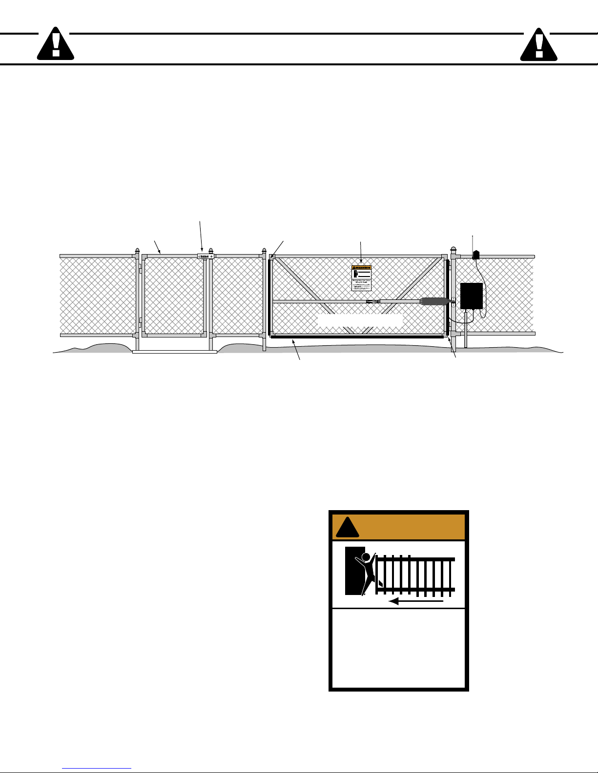
1. KEEP CLEAR! Gate may move at any time.
2. Do not allow children to operate gate or
play in gate area.
3. This gate is for vehicles only. Pedestrians
must use a separate entrance.
Moving Gate Can Cause
Injury Or Death
WARNING
!
Warning Sign
Pedestrian Gate
Bulldog Pedestrian
Gate Lock
Vehicular Gate
Contact Sensor
(recommended, not included)
Contact Sensor
(recommended, not included)
Contact Sensor
(recommended, not included)
(recommended, not included
)
Required Safety Precautions for Gates
Install Warning Signs
Warning signs alert people of automatic gate operation and are required when installing the GTO/PRO® 3000 Automatic
Gate Operator. Furthermore, a walk-through gate must be installed if pedestrian traffic is expected near the vehicular gate.
We recommend using the GTO Bulldog Pedestrian Gate Lock (Call the GTO Sales Department) for controlled access.
Entrapment Protection
GTO’s inherent obstruction settings, even when properly adjusted, may not be sensitive enough to prevent bodily injury in
some circumstances. For this reason, safety devices such as safety edge sensors (or photoelectric sensors), which stop and
reverse gate direction upon sensing an obstruction, are suggested for enhanced protection against entrapment.
Warning Signs
The warning signs (at right) must
be installed on both sides of the
gate (see page 7 for details).
6
Page 11

!
Warning signs (2 enclosed) to be installed on each side
of the gate (3–5 feet above the bottom of the gate)
Maximum Gate: 650 lb. (294.8 kg); 16 ft. (4.8 m)
Voltage: 12 Vdc; Frequency: 0 Hz; Power: 40 W
Class I, II, III and IV Vehicular Swing Gate Operator
.
Serial Number: XXXXXXXXXX
#xxxxxxx
Conforms to UL 325 STANDARDS
TO MANUALLY OPEN AND CLOSE THE GATE:
1. Turn control box power switch OFF
.
2. Disconnect front or rear mount from gate bracket
.
3. Pull operator away from front or real mounts.
DC SW-3000 SERIES
GTO, Inc. Tallahassee, Florida USA
Disconnect operator ONLY when the control box power
switch is OFF and the gate is NOT moving.
L
I
S
T
E
D
US
C
Product identification and manual operation instruction
label (1) installed on control box cover
Logo and warning labels (2) installed on each side of operator housing.
1. KEEP CLEAR! Gate may move at any time.
2. Do not allow children to operate gate or play in
gate area.
3. This gate is for vehicles only
. Pedestrians must
use separate entrance.
WARNING
!
MOVING GATE
Can Cause Injury or Death
®
DC-SERIES
1-800-543-GATE (4283) • www.gtopro.com
IMPORTANT SAFETY INSTRUCTIONS
These warning labels should be found
at the locations specified below.
If any of them are missing,
immediately contact GTO for
replacements.
7
Page 12
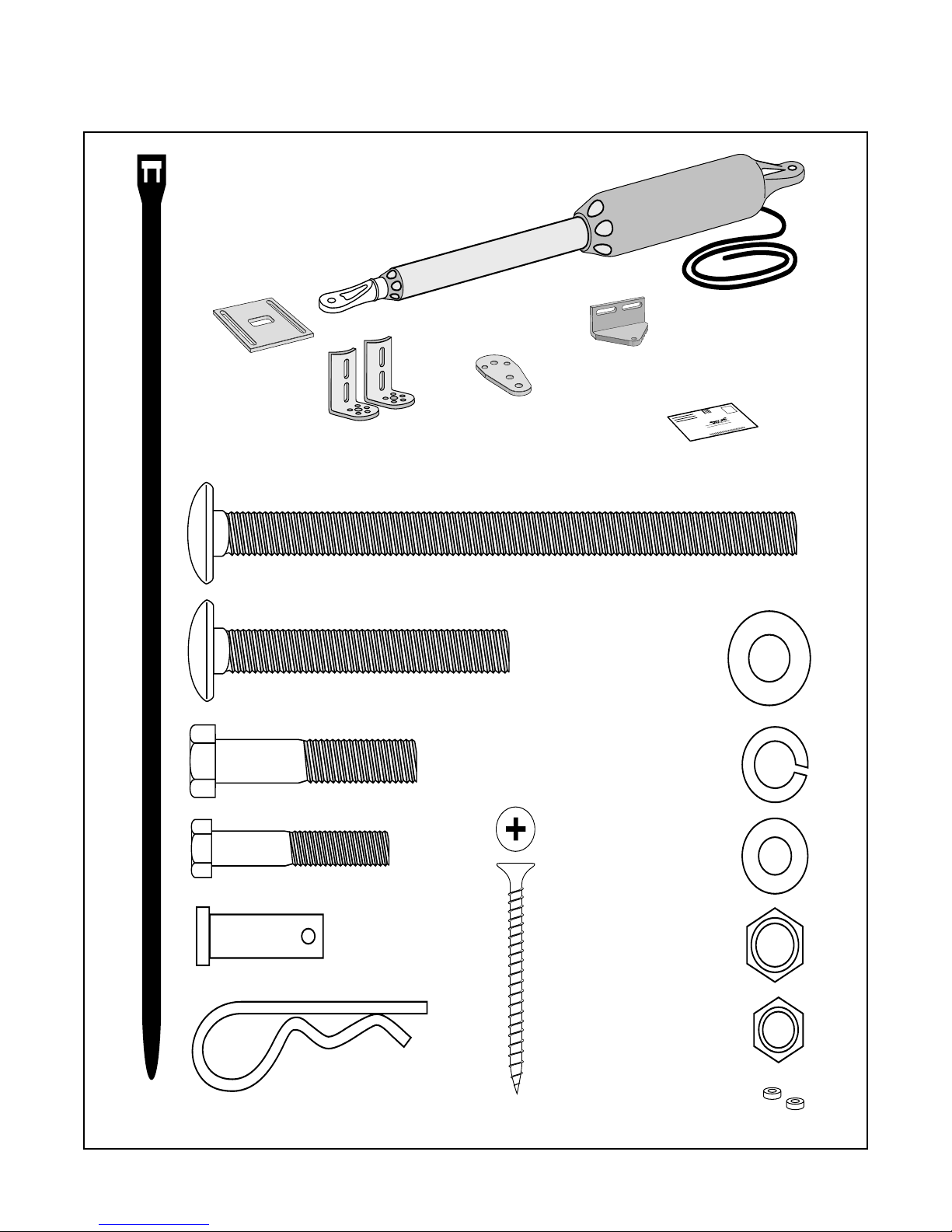
Single Gate Operator Parts List
Hairpin Clip (2)
3/8" x 1-1/4" Clevis Pin (2)
5/16" x 1-3/4" Bolt (1)
3/8" x 2" Bolt (1)
3/8" x 3" Bolt (2)
3/8" x 8" Bolt (4)
8" Nylon Cable Tie (14)
3/8" Washer (9)
3/8" Lock Washer (7)
5/16" Washer (1)
3/8" Nut (7)
5/16" Nut (1)
Hardware
Gate Operator (1)
w/ 6' Power Cable
Gate Bracket (1)
Post Pivot Bracket (1)
Customer Support Card (1)
Post Bracket (2)
Closed Position
Stop Plate (1)
2" Receiver Mounting Screw (5)
®
E
-
Z
G
A
T
E
O
P
E
N
E
R
3/8" Bushings (2)
Operator and Mounting Hardware
8
Page 13

Single Gate Operator Parts List (continued)
ON/OF
F
Transformer (1)
Battery (1)
Control Box (1)
Warning Signs (2)
GTO Transmitter(1)
1. KEEP CLEAR! Gate may move at any time.
2. Do not allow children to operate gate or
play in gate area.
3. This gate is for vehicles only.
Pedestrians
must use a separate entrance.
Moving Gate Can Cause
Injury Or Death
WARNING
!
Receiver (1)
Control Box and Electrical Components
Tools Needed
• Power Drill
• Open End Wrenches — 3/8", 7/16", 1/2", and 9/16"
• 3/8" Drill Bit
• Hacksaw or Heavy Duty Bolt Cutters
• Small (Flat Bladed) Screwdriver
• Phillips Screwdriver
• Tape Measure
• Level
• Wire Strippers
• C-Clamps — small, medium, and large
• Center Punch
• Extra person will be helpful
YOU MAY ALSO NEED THESE ITEMS BEFORE YOU BEGIN THE INSTALLATION
(Some of these items can be found in the Accessory Catalog page 37):
• Low voltage wire will be needed to run from the transformer to the control box; length depends upon the distance
between the transformer power supply and the control box. See Powering the System on page 19, and the
Accessory Catalog.
• If your gate is more than 1000' away from an ac power source you will need to use at least 5 watts of solar charging
power to trickle charge the battery. See the Accessory Catalog.
• If your fence post is made of wood and is less than 6" in diameter or 6" square, see page 12.
• If your fence post is larger than 6" in diameter you will need threaded rods or carriage bolts longer than 8". See
page 15.
• PVC conduit.
• If you have thin walled tube or panel gates, see Recommended Reinforcement Examples on page 12.
• Depending on the type of gate, a horizontal cross member or mounting plate may be needed to mount the front of
the opener and gate bracket to the gate. See page 11, step 2; page 15, step 10.
• Surge protection for transformer.
• Some types of installations require U-Bolts.
9
Page 14
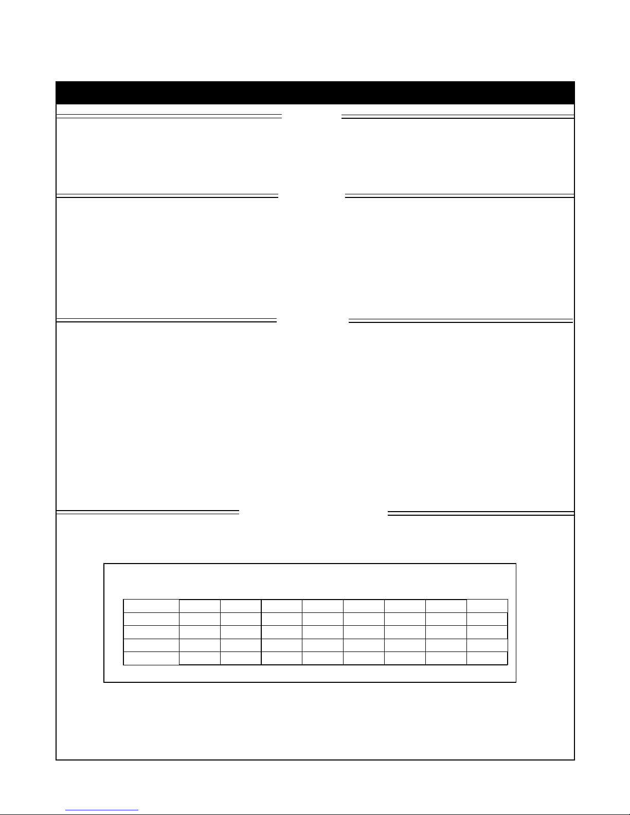
Technical Specifications
Gate Weight
Gate Length
GTO/PRO® 3000 Gate Capacity Chart
Estimated number of daily cycles, based on use with a transformer and one(1) 12 Volt battery
16 ft.
14 ft.
12 ft.
up to10 ft.
160
170
180
190
50 lb.
150
160
170
180
100 lb.
140
150
160
170
150 lb.
130
140
150
160
200 lb.
120
130
140
150
300 lb.
110
120
130
140
400 lb.
100
110
120
130
500 lb.
90
100
110
120
650 lb.
GTO/PRO® 3000 AUTOMATIC GATE OPERATOR
DRIVE
• Low friction screw drive (linear actuator) rated for -5 ºF to +160 ºF (-28 ºC to +71 ºC). Use of heater bans on arm and
control box will enhance performance in extreme cold temperatures.
• Powered by a 12 V motor with integral case hardened steel gear reducer. Motor speed reduced to 260 rpm. Generates
820 ft.. lb. of torque at 12 V.
• Maximum opening arc of 110º. Approximate opening time (90º): 20 seconds, depending on weight of gate.
POWER
• The system is powered by a 12 Vdc, 7.0 Ah, sealed, rechargeable acid battery.
• Battery charge is maintained by a 120 Vac, 18 Vac output transformer rectified to 14.5 Vdc (40 VA) through the GTO
control board. Blade-style control board fuse is rated for 25 A.
NOTE: The transformer should not be directly connected to any battery. Do not replace fuses
with higher ampere rated fuses; doing so will void your warranty and may damage your control board.
• Battery charge is maintained by GTO Solar Panel Charger: float voltage of 14.5 Vdc output from a 19
silicon alloy panel. Generates minimum of 5 W at 300 mA. A gated diode on the control board prevents battery discharge.
CONTROL
• GTO microprocessor-based control board is set for single leaf, pull-to-open gate installations. DIP switches can be
adjusted to accommodate an optional kit for push-to-open gates (see Accessory Catalog).
• Control board has temperature compensated circuits.
• A circuit on the control board regulates charging. "Sleep draw" is 40 mA; "active draw" is 3 to 7 A.
• Auto-memorization of digital transmitter code.
• GTO remote-mounted RF receiver tuned to 318 MHz.
1
• Operator length with push-pull tube fully retracted is 40
/
4", mounting point to mounting point.
• Adjustable auto-close timer (OFF to 120 s), and obstruction sensitivity.
• Power terminal bock accommodates a transformer and solar panels.
• DIP switches simplify setup of gate operator.
• Accessory terminal block fully compatible with push button controls, digital keypads, safety loops, etc.
• Control board allows connection of safety edge sensors and photoelectric sensors.
• Audio entrapment alarm sounds if unit encounters an obstruction twice while opening or closing.
3
/
8" x 8
1
/
2"
OPERATIONAL CAPACITY
• The Gate Capacity Chart shows approximate cycles, per day, you can expect from the GTO/PRO® 3000 Automatic
Gate Operator when powered with a transformer. Actual cycles may vary slightly depending upon the type and condition of gate and installation.
NOTE: BALL BEARING HINGES SHOULD BE USED ON ALL GATES WEIGHING OVER 250 LB.
To determine the number of cycles the gate operator will perform using solar panels, please see the specifications
listed on page 20 or call (800) 543-1236 or (850) 575-4144 for more information.
* An operation cycle is one full opening and closing of the gate.
These specifications are subject to change without notice.
10
Page 15
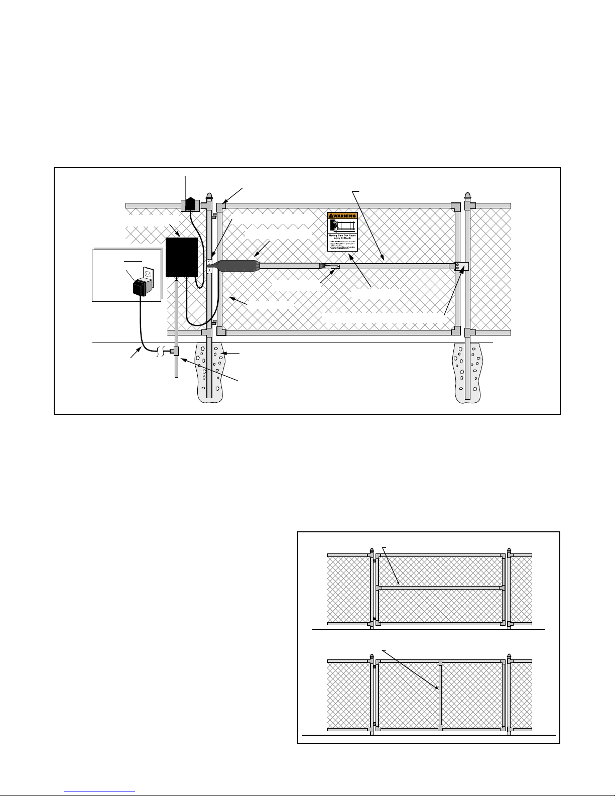
Installation Overview
Horizontal Cross Member
Vertical Cross Member
Horizontal Cross Member
Gate Swings Evenly and Freely
Hung Firmly and Plumb
Receiver
Post Bracket Assembly
Control Box with Battery
Gate Bracket
Single Gate Opener
Fence Post Set in Concrete
Run 1000' (max.) of low
voltage wire to control
box from transformer
(wire not included).
Power Cable
Closed Position Positive Stop Plate
120 Volt indoor
Transformer
(surge protector
not supplied)
PVC conduit (not included)
to protect wire from lawn
mowers and weed eaters.
Warning Sign
Pull-to-Open Gates (Gate Opens into the Property)
The diagram shown below is an example of a pull-to-open installation on a chain link fence and single gate. Mounting the
operator on a masonry column requires special procedures; see Column Installation Information on page 36 if you intend
to mount the operator on a column. Furthermore, if you have a push-to-open gate, you will need to purchase a push-to-open
bracket (see Accessory Catalog) to properly configure your system. See Push to Open Installation on page 30 before
proceeding.
Preparation of the Gate
Step 1
The gate must be plumb, level, and swing freely on its
hinges. Wheels must not be attached to the gate. The
gate must move throughout its arc without binding or
dragging on the ground. Note that gates over 250 lb.
should have ball bearing hinges with grease fittings.
Step 2
The fence post must be secured in the ground with
concrete so it will minimize twist or flex when the
operator is activated. We recommend you position the
operator near the centerline of the gate to keep the gate
from twisting and flexing. The addition of a horizontal
or vertical cross member (if one is not already in place)
to provide a stable area for mounting the gate bracket is
also important.
11
Page 16

Installation of Mounting Hardware
Post
Bracket
Post
Pivot Bracket
Metal Plate
Wooden Post
Post
Bracket
Post
Pivot Bracket
Metal Plate
Wooden Post
Thin Walled Tube Gate
Steel Pipe Cut in Half
Gate Bracket
Gate Bracket
Wood or Metal
Reinforcement
Gate Bracket
Panel Gate
1" x 6" Wood Reinforcement
(not supplied)
(not supplied)
Center of Gate Hinge
Pull-to-Open Installation
Larger than 6" diameter post
The position of the post bracket determines the leverage and efficiency of the operator. The post bracket position also sets the
clearance between the operator and gate in the open and closed positions (minimum 2 inches for safety reasons).
The curved design of the post bracket works well for installations on round and square fence posts. Because the post bracket
carries the entire thrust of the active operator, bolts that completely penetrate the fence post must be used.
On wooden posts, place a metal plate or washer
(not supplied) between the nuts and the fence
post to prevent the thrust of the operator from
pulling the bolts and washers out of the wood.
NOTE: A fence post smaller than 6" in diameter
or 6" square should be made of metal instead
of wood so that it will remain stable while the
operator is moving the gate.
On round posts of 6" diameter or larger, the post pivot bracket may
not be necessary for the installation. In this instance, the two post
brackets are mounted by themselves.
IMPORTANT:
We strongly recommend using steel pipe, wood or metal to reinforce thin walled tube gates or wood to reinforce panel gates
as shown. These reinforcement methods will prevent damage to the operator and gate when the operator is installed.
Recommended Reinforcement Examples
12
Page 17
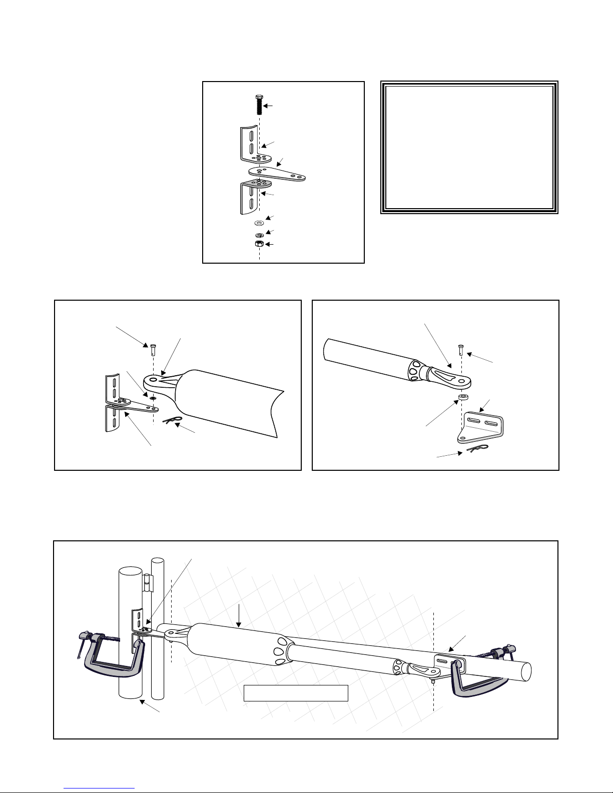
Determining the Mounting Position
3/8" x 2" Bolt
3/8" Nut
Post Pivot Bracket
Post Bracket
Post Bracket
3/8" Lock Washer
Post Bracket Assembly
3/8" Washer
Clevis Pin
Hairpin Clip
Post Bracket Assembly
Bushing
Rear Mount
Operator
Clevis Pin
Hairpin Clip
Gate Bracket
Front Mount
Bushing
Level Operator
Fence Post
Gate In Open Position
LEVEL horizontal cross member
Post Bracket Assembly
Gate Bracket
of the Post Bracket Assembly and the Gate Bracket
Step 3
Insert the 3/8" x 2" bolt through
the center hole of the post
brackets and post pivot bracket
as shown. Fasten a 3/8" lock
washer, 3/8" washer and 3/8" nut
on the end of the bolt. DO NOT
overtighten the nut because the
post pivot bracket will have to be
adjusted later.
NOTE: The following steps are
intended for pull-to-open gate
installations. If you are mounting
your operator on a push-to-open gate
(e.g., a gate on a sloped driveway)
you will need to purchase a Push
To Open bracket (see Accessory
Catalog). Also, see Push-to-Open
Installation beginning on page 30.
Step 4
Attach post bracket assembly and gate bracket to the operator with the clevis pins and bushings. Secure the clevis pins with
hairpin clips.
Step 5
With the gate in the open position (up to 110º from its closed position) and the operator fully retracted, adjust the
post bracket assembly and gate bracket until the operator is level. While holding the operator level, use C-clamps to
temporarily keep the post bracket assembly and gate bracket in their respective positions on the fence post and gate.
13
Page 18
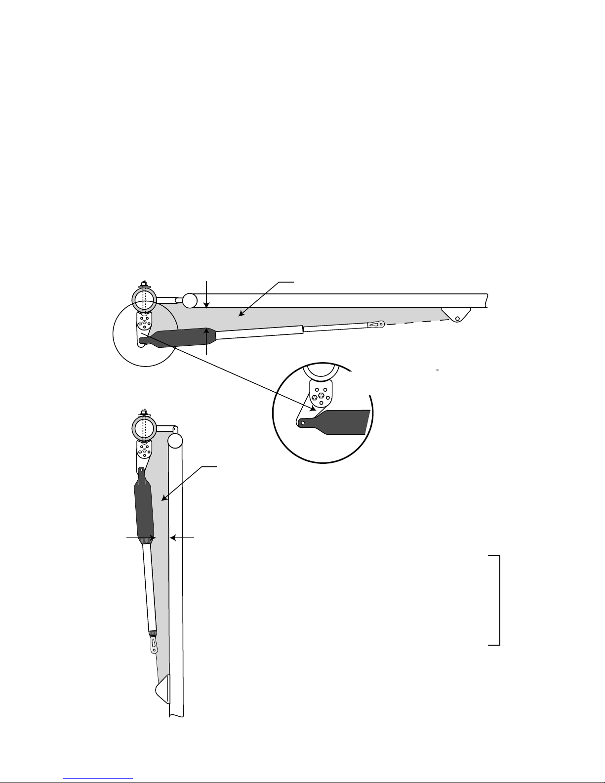
IMPORTANT: While determining the mounting point for the post pivot bracket assembly, be sure that the position allows
Gate in the
CLOSED POSITION
Pinch Area
Gate in the
OPENED POSITION
Pinch Area
2" minimum
2" minimum
Be sure gate opener
and bracket don't bind.
for minimum 2 inches of clearance between the gate and the operator in both the open and closed positions, as shown in the
diagrams below. This clearance will give the operator the most efficient leverage point for opening and closing the gate and
more importantly provides the least possible pinch area.
Step 6
When you feel that you have the best position for the post pivot bracket in the open position, insert the 5/16" x 1-3/4" bolt
through the aligned holes of the post bracket and post pivot bracket to hold it in place. Remove the clevis pin from the front
mount and while supporting the gate operator, swing the gate and gate operator to the closed position. With the gate and gate
operator in the closed position check the clearance and be sure that the gate operator is not binding at the post pivot bracket.
If you don't have 2 inches of clearance or the gate operator is binding on the post pivot bracket, remove the 5/16" x 1-3/4"
bolt and readjust the pivot bracket until you can achieve these important clearances.
With the post pivot bracket in the optimum position for clearance and freedom of movement, reattach the operator to the gate
bracket in the open position and recheck the gate operator level and make sure the brackets are clamped securely.
TIP: Turning the pivot bracket over gives
more hole alignment options for the post
pivot bracket assembly. You can also move
the entire post pivot bracket assembly to
different positions on the gate post to help
achieve the proper clearances.
14
Page 19
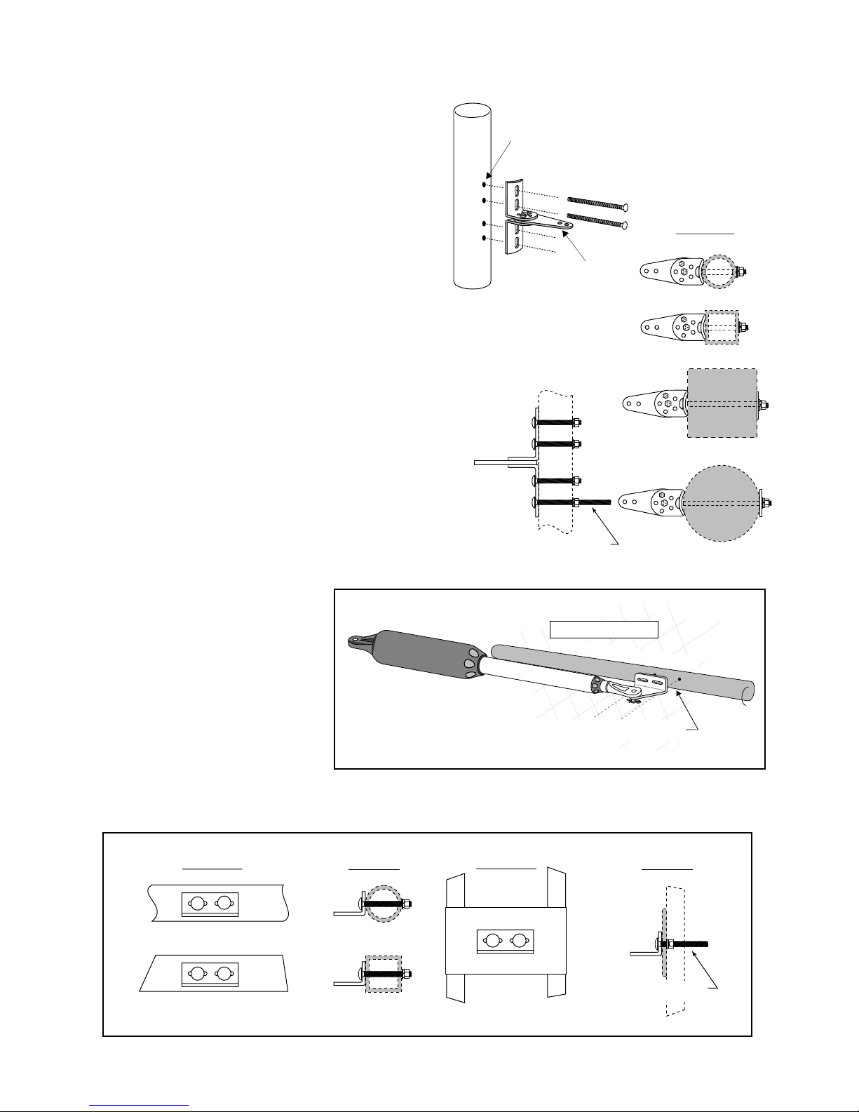
Installing the Post Bracket Assembly and Gate
Round Tube & Chain Link Gate
Square Tube Gate
Mounting Plate
Created for
Decorative Gate
(required but not
supplied)
Remove excess bolt length
with hacksaw or bolt cutters
FRONT VIEW
SIDE VIE
W
FRONT VIEW
SIDE VIEW
Round Metal Post
Round Wood Post
Square Metal Pos
t
Square Wood Pos
t
Remove excess bolt length
with hacksaw or bolt cutters
SIDE VIEW
TOP VIEW
EXAMPLES
Post Bracket
Assembly
Mark fence post through
middle of bracket slots
and drill 3/8" holes
Gate In Open Position
LEVEL horizontal cross member
Mark cross member through middle of
gate bracket slots and drill 3/8" holes
Step 7
Mark reference points for bolt holes on the fence post through
middle of bracket slots. Marking reference points in this manner
allows room for adjustment when mounting the post bracket
assembly and gate bracket. After marking your reference points,
remove the operator and brackets from the fence and gate.
Step 8
Drill 3/8" holes into fence post as marked.
Step 9
Fasten post bracket assembly to the fence post using
(4) 3/8" x 8" bolts, washers, lock washers, and nuts (provided).
Remove excess bolt length extending beyond the tightened nuts
with a hacksaw or bolt cutters.
NOTE: In cases where the fence post has a diameter larger than
6", threaded rods or carriage bolts longer than 8"
(not supplied) must be used.
Step 10
Mark reference points for bolt holes on the gate cross member
through middle of gate bracket slots. Drill 3/8" holes into the
gate cross member as marked.
Mount gate bracket using (2)
3
/8" x 3" bolts, washers, lock washers, and
nuts (provided). Cut off excess bolt length
extending beyond the tightened nuts.
Gate Bracket Mounting Examples
15
Page 20
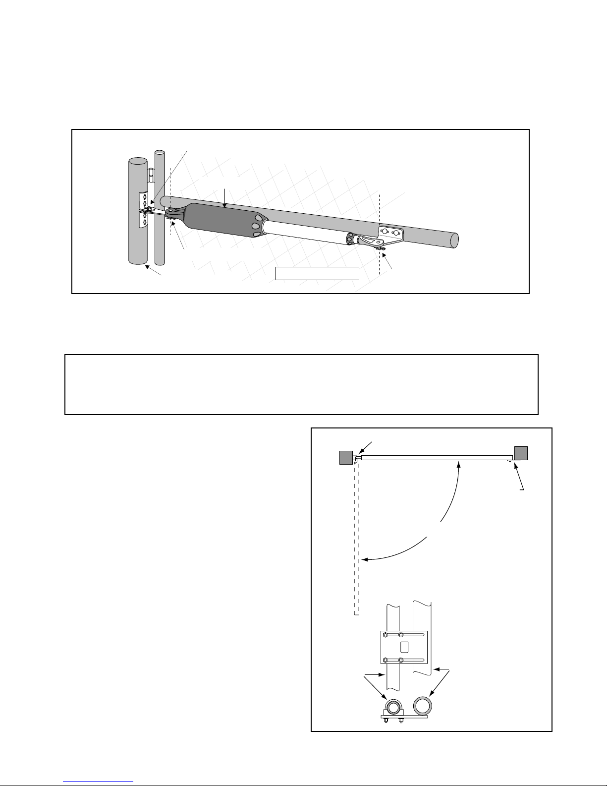
Mounting the Operator
Closed Position
Stop Plate
Closed Position Stop Plate mounted
on metal post with U-bolts.
Gate Hinge
The gate must open
80º (min.) to 110º (max.)
Fence Post
Gate Post
TOP VIEW
SIDE VIEW
Level Operator
Fence Post
Gate In Open Position
LEVEL horizontal cross member
Post Bracket Assembly
bolted to fence post
Clevis Pin, Bushing and Hairpin Clip
Clevis Pin, Bushing, and Hairpin Clip
Gate Bracket bolted
to gate cross member
Step 11
Attach the operator to the securely bolted post bracket assembly and gate bracket using clevis pins, bushings, and hairpin
clips, or optional Pin Locks (see Accessory Catalog). Verify that the operator is level and adjust the post bracket assembly if
necessary.
Installation of the Closed Position Stop
The GTO/PRO® 3000 Gate Operator firmly holds the gate in the closed position using the positive stop plate. The
positive stop helps stabilize the gate leaf in the closed position. To further enhance the stability and security of
your gate, install the optional GTO/PRO® Automatic Gate Lock (see Accessory Catalog).
Step 12
Remove hairpin, clevis pin, and washer from front mount
and close the gate (remember to support operator). Fasten
the closed position stop plate to the end of the gate frame on
the gate centerline, but do not tighten it completely. Slide
the stop plate toward the fence post until they touch (see
illustration). Once you have moved the stop plate to the
correct position, tighten its hardware completely.
Use the appropriate hardware for your type of gate (use
U-bolts if you have a tube or chain link gate; wood or lag
screws for wood gates; etc.). This hardware is not provided.
16
Page 21

At this stage of the installation, the operator should be installed on
Use mounting
holes and screws
provided to mount
control box to a
secure surface.
1ON23 45 6 7
1ON23 4
15
18VAC RECEIVER
BAT
+
SWITCH
FUSE
ALARM
SWITCH
DUAL
MODE
S
SET
LIMI
T
LEARN
TRANSMITTE
R
MODES
ON
OFF
ON
OF
F
1 2 3 4 5 6 7
1 2 3 4
BAT
–
SOLAR RELAY OUT SLAVE INPUTS
GRN WHT BLUE BRN ORG RED BLKNCRLY-COM NO
MASTER INPUTS
GRN WHT BLUE BRN ORG RED BLK COM COM
CYCLE
CLOS
E
SAFETY
EXIT
/
OPE
N
SHADOW
LOOP
CLOS
E
EDGE
OPE
N
EDGE
BLKGRN RED
+–~~
12'
10'
8'
14'
16'
GATE LENGT
H
800-543-GATE
www.gtoinc.com
GTO, Inc.
3121 Hartsfield Rd
Tallahassee, FL 32303
Closed Position Stop Plate
Gate In Closed Position
C
L
Single Battery
Installed Horizontally
with terminals on the right.
Dual Batteries
Installed Vertically
with terminals on bottom.
the gate and the closed position stop should be in place.
Check List
• The gate is plumb, level, and swings smoothly on its hinges.
• A plate or support was added for the gate bracket (if necessary).
• The operator is level and mounted on the centerline of the gate.
Mounting the Control Box
Step 13
Mount the control box using the screws (provided) or another
secure mounting method. The control box must be mounted at
least 3 feet above the ground to protect it from rain splash, snow,
etc., and at least 3 feet from an AC power source to prevent
electrical interference.
NOTE: The battery that came with your GTO/PRO® 3000 ,
MUST be placed horizontally battery with the terminals on the
RIGHT. If an optional second battery is needed, both batteries
must be placed vertically with terminals at the bottom. An
applications, if needed..
optional second battery can be used for solar and/or high traffic
17
Page 22
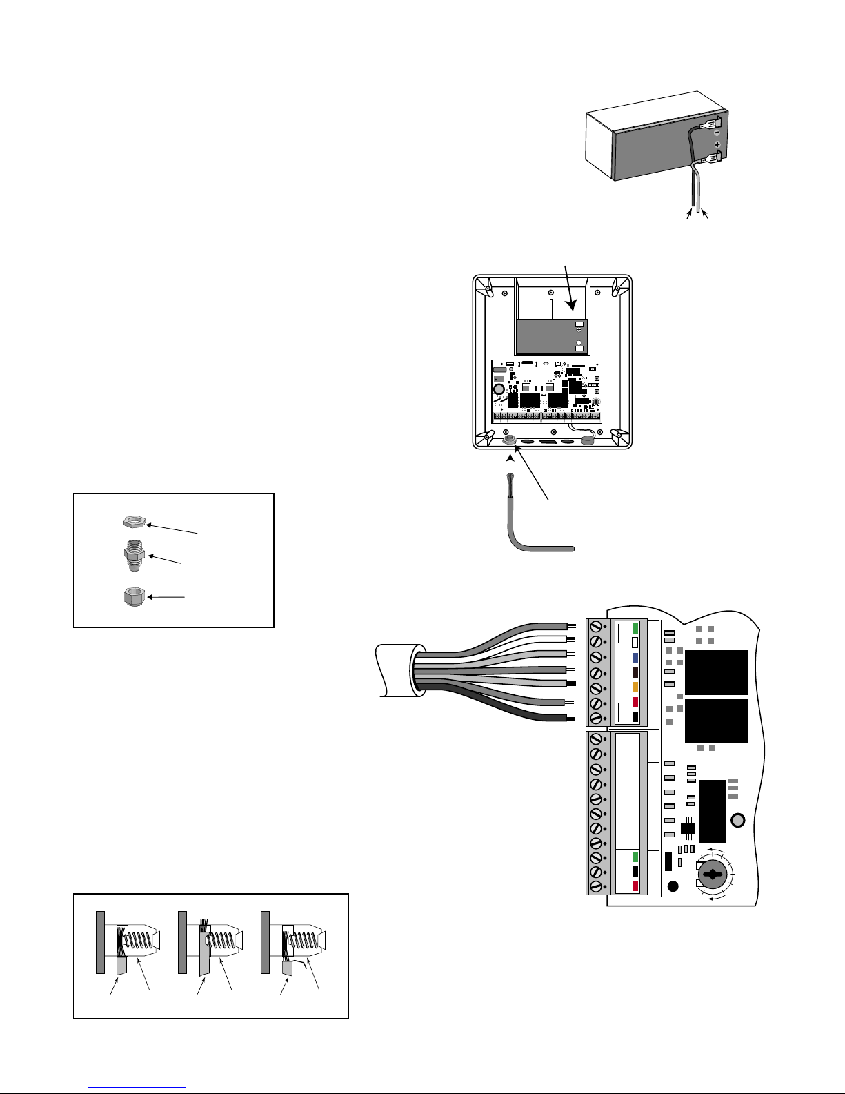
Power cable from
operator (master) arm
SWITCH
STALL FORCE
M
I
N
M
A
X
MASTER INPUTS
GRN
WHT
BLUE
BRN
ORG
RED
BLK
GRN
BLK
RED
RECEIVER
COM COM
CYCLE
CLOSE
SAFET
Y
EXI
T
OPEN
SHADOW
LOOP
CLOSE
EDGE
OPEN
EDGE
J11
J8J5J13
J12
Correct
Wrong Wrong
Wire
Terminal
Block
Terminal
Block
Terminal
Block
Wire
Wire
Connecting Operator Power Cable
Sealing Nut
Hub
Lock Nut
Strain Relief
RED wire to POSITIVE (+) terminal
BLACK wire to NEGATIVE (—) terminal
RED
BLACK
Operator Power Cable
12 V Battery (Included)
Strain Relief
1ON2 3 4 5 6 7
1ON2 3 4
15
18VAC RECEIVER
BAT
+
SWITCH
FUSE
ALARM
SWITCH
DUAL
MODE
S
SET
LIMI
T
LEARN
TRANSMITTE
R
MODE
S
ON
OF
F
ON
OF
F
1 2 3 4 5 6 7
1 2 3 4
BAT
–
SOLAR RELAY OUT SLAVE INPUTS
GRN WHT BLUE BRN ORG RED BLKNCRLY-COM NO
MASTER INPUTS
GRN WHT BLUE BRN ORG RED BLK COMCOM
CYCLE
CLOS
E
SAFET
Y
EXIT
/
OPEN
SHADOW
LOOP
CLOS
E
EDGE
OPEN
EDGE
BLKGRN RED
+–~~
12'
10'
8'
14'
16'
GATE LENGT
H
800-543-GATE
www.gtoinc.com
GTO, Inc.
3121 Hartsfield Rd
Tallahassee, FL 32303
Step 14
Make sure the control box power switch is in the OFF position.
The ON/OFF Switch is located on the bottom of the control box.
Remove the control box cover and slide the battery into position
with its terminals to the RIGHT (see illustration). Connect the
BLACK battery wire to the NEGATIVE (–) battery terminal.
Connect the RED battery wire to the POSITIVE (+) terminal. Pay
close attention to the color of the wires. If the wires are connected
incorrectly, the control board may be damaged. NEVER insert
the battery with the terminals to the left.
Step 15
Strip approximately 3/16" of insulation from each wire
of the operator power cable. Twist each exposed wire
tightly (there are seven [7] wires inside the power cable
sheath). Loosen sealing nut on strain relief hub at
bottom of control box. Insert power cable into control
box through strain relief. Thread approximately 6" of the
power cable into the control box and retighten sealing nut
until the power cable locks into place.
Step 16
Insert the stripped operator power cable wires into
the appropriate terminals on the OPERATOR
terminal block. The green wire should be inserted
into the GRN terminal, the blue wire into BLU, the
orange wire into ORG, black wire into BLK, and
the red wire into the RED terminal.
Tighten the set screws against the end of the wires.
A dab of petroleum jelly on each terminal will help
prevent corrosion. Do not overtighten.
18
Page 23
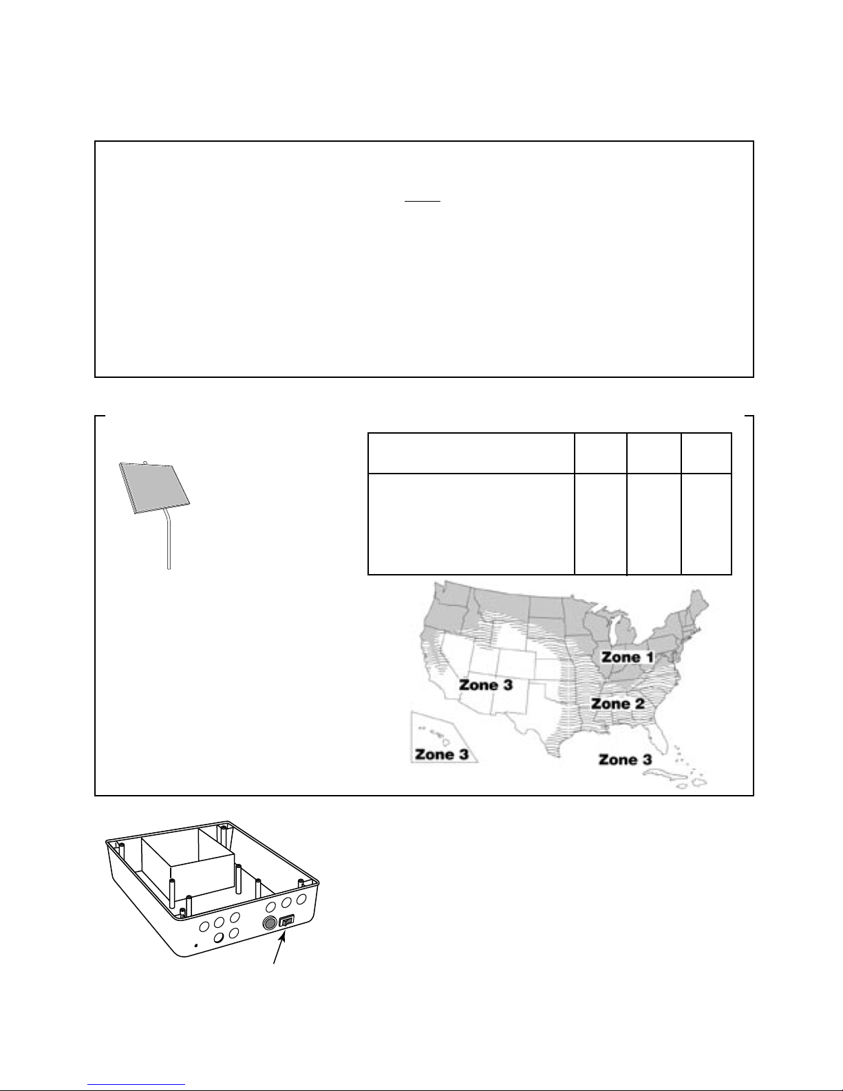
Powering the System
ON/OFF Switch
ON/OFF
Installation of the Transformer
IMPORTANT:
• The transformer is designed and intended for indoor use. If the transformer can be plugged only into
an outside electrical outlet, a weatherproof cover or housing (available at local electrical supply stores)
must be used.
• All low voltage wire used with the GTO/PRO® 3000 Gate Operator must be 16 gauge dual conductor,
multi-stranded, direct burial wire (see page 20) and the Accessory Catalog). Do not run more than
1000 feet of wire.
• If your gate is more than 1000 ft. from an ac power source, you will need to use at least one 5 watt
Solar Panel to charge the battery (see Accessory Catalog). Refer to the Solar Panels and Gate
Activity chart below.
Optional Solar Panels and Gate Activity
The table and map illustrate
the maximum number of
gate cycles to expect per
day in a particular area
when using from 5 to 30
watts of solar charging
power. (see Accessory
Catalog). The figures
shown are for winter
(minimum sunlight) and do not account for
the use of any accessory items. Accessories
connected to your system will draw additional
power from the battery.
NOTE: A maximum of 30 watts of solar
charging power can be connected to the
GTO/PRO® Gate Operator. Consult Solar
Panel Installation Instructions for further
information.
Winter Ratings Zone 1 Zone 2 Zone 3
12 v single gate (5 watts) solar charger 4 8 13
12 v single gate (10 watts) solar charger 8 16 26
12 v single gate (15 watts) solar charger 11 20 30
12 v single gate (20 watts) solar charger 14 28 38
12 v single gate (25 watts) solar charger 17 36 46
12 v single gate (30 watts) solar charger 20 44 54
Step 1
Make sure the power switch is OFF before proceeding to the next step.
Step 2
Select the electrical outlet into which you will plug the transformer.
Measure the distance from this outlet to the control box following the
path where the wire will be laid. After you have measured how much
wire is needed, cut the wire to the appropriate length.
19
Page 24
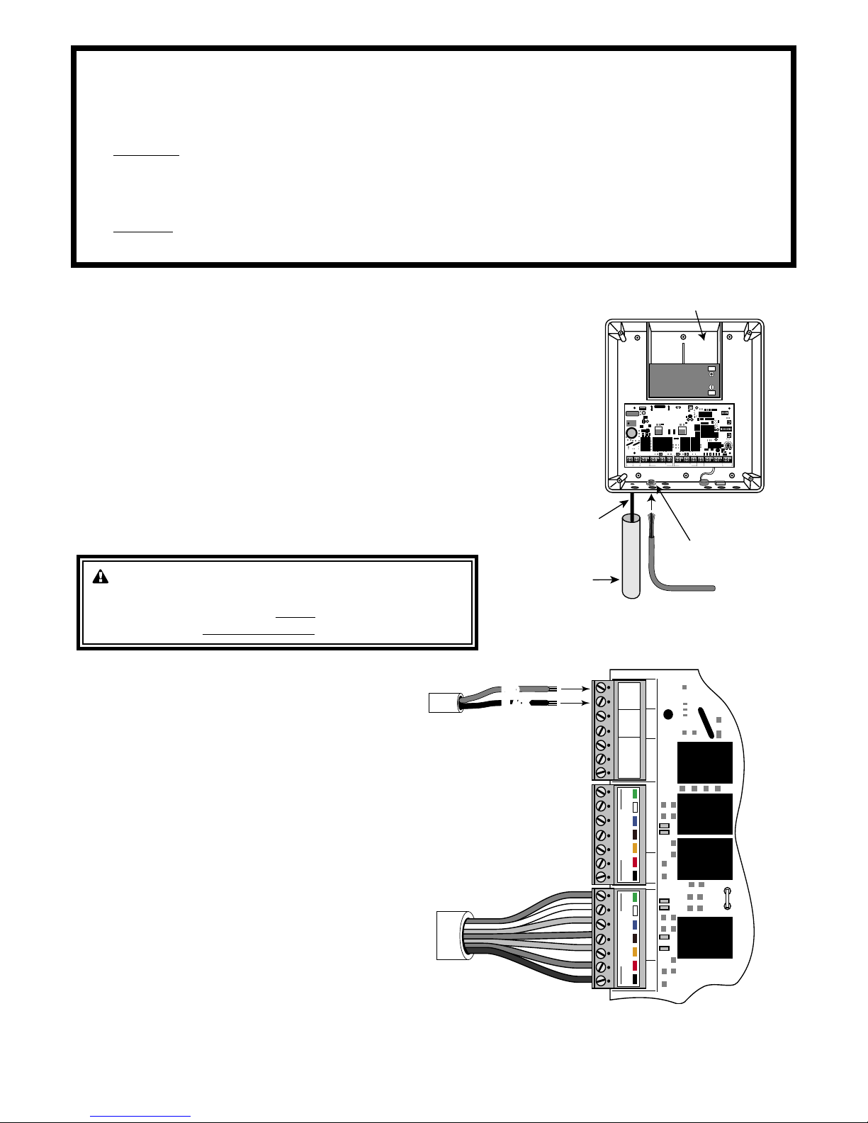
IMPORTANT INFORMATION ABOUT LOW VOLTAGE WIRE
Power Cable
from Operator (master)
RED
BLACK
RED
BLACK
Low Voltage Wire
from AC Transformer
SWITCH
18 VAC SOLAR RELAY OUT
~ ~ - +
NC NORLY-COM
SLAVE INPUTS
GRN
WHT
BLUE
BRN
ORG
RED
BLK
MASTER INPUTS
GRN
WHT
BLUE
BRN
ORG
RED
BLK
J5J13J21J6J9J2J1
Low Voltage Wire
from Transformer
or Solar Panel
PVC Pipe
Operator Power Cable
12 V Battery
Strain Relief
1ON2 3 4 5 6 7
1ON2 3 4
15
18VAC RECEIVER
BAT
+
SWITCH
FUSE
ALARM
SWITCH
DUAL
MODES
SET
LIMI
T
LEAR
N
TRANSMITTE
R
MODE
S
ON
OF
F
ON
OF
F
1 2 3 4 5 6 7
1 2 3 4
BAT
–
SOLAR RELAY OUT SLAVE INPUTS
GRN WHT BLUE BRN ORG RED BLKNCRLY-COM NO
MASTER INPUTS
GRN WHT BLUE BRN ORG RED BLK COM COM
CYCLE
CLOS
E
SAFET
Y
EXIT/
OPEN
SHADOW
LOOP
CLOS
E
EDGE
OPEN
EDGE
BLKGRN RED
+–~~
12'
10'
8'
14'
16'
GATE LENGT
H
800-543-GATE
www.gtoinc.com
GTO, Inc.
3121 Hartsfield Rd
Tallahassee, FL 32303
The only wire acceptable for use with GTO products is 16 gauge multi-stranded, low voltage, PVC
sheathed wire. This particular gauge enables the transformer to provide an adequate charge through the
control board to the battery at distances up to 1000 ft.
DO NOT use telephone wire or solid core wire. Unlike multi-stranded wire, these types of wire are
inadequate for use with your gate operator system. Telephone wire and solid core wire do not deliver
enough voltage for your gate operator to function and will cause the system to go into a condition known
as "low voltage lockout."
NEVER splice wires together. Splicing permits corrosion and seriously degrades the wire's ability to
carry an adequate current.
Step 3
Lay the measured length of low voltage wire in a trench following a path from
the selected electrical outlet to the control box. Wires coming up from the
ground should be run through PVC conduit to protect them from lawn mower
blades, weed eaters, and grazing animals. Be sure to bury the wire laid in the
trench.
Step 4
Feed the low voltage wires upward through the strain relief opening on the
lower left of the control box. Pull 6" to 8" of wire into the control box and
tighten the strain relief screw to secure the wires.
WARNING! DO NOT PLUG THE TRANSFORMER
INTO AN OUTLET DURING THIS STEP! THE
TRANSFORMER MUST ONLY BE PLUGGED INTO
AN OUTLET DURING STEP 7!!
Step 5
Strip 3/16" off the ends of the low voltage wire
and twist tightly. Attach these ends to the 18VAC
terminals located on the POWER IN terminal block
(see illustration at right). Be certain not to let the
exposed wires touch each other!
Insert one transformer wire into an 18VAC terminal.
Insert the other transformer wire into the remaining
18VAC terminal. The transformer wires can be
connected to the 18VAC terminals regardless of color.
Tighten set screws against exposed end of wires. A
dab of household petroleum jelly on each terminal will
help prevent corrosion.
20
Page 25
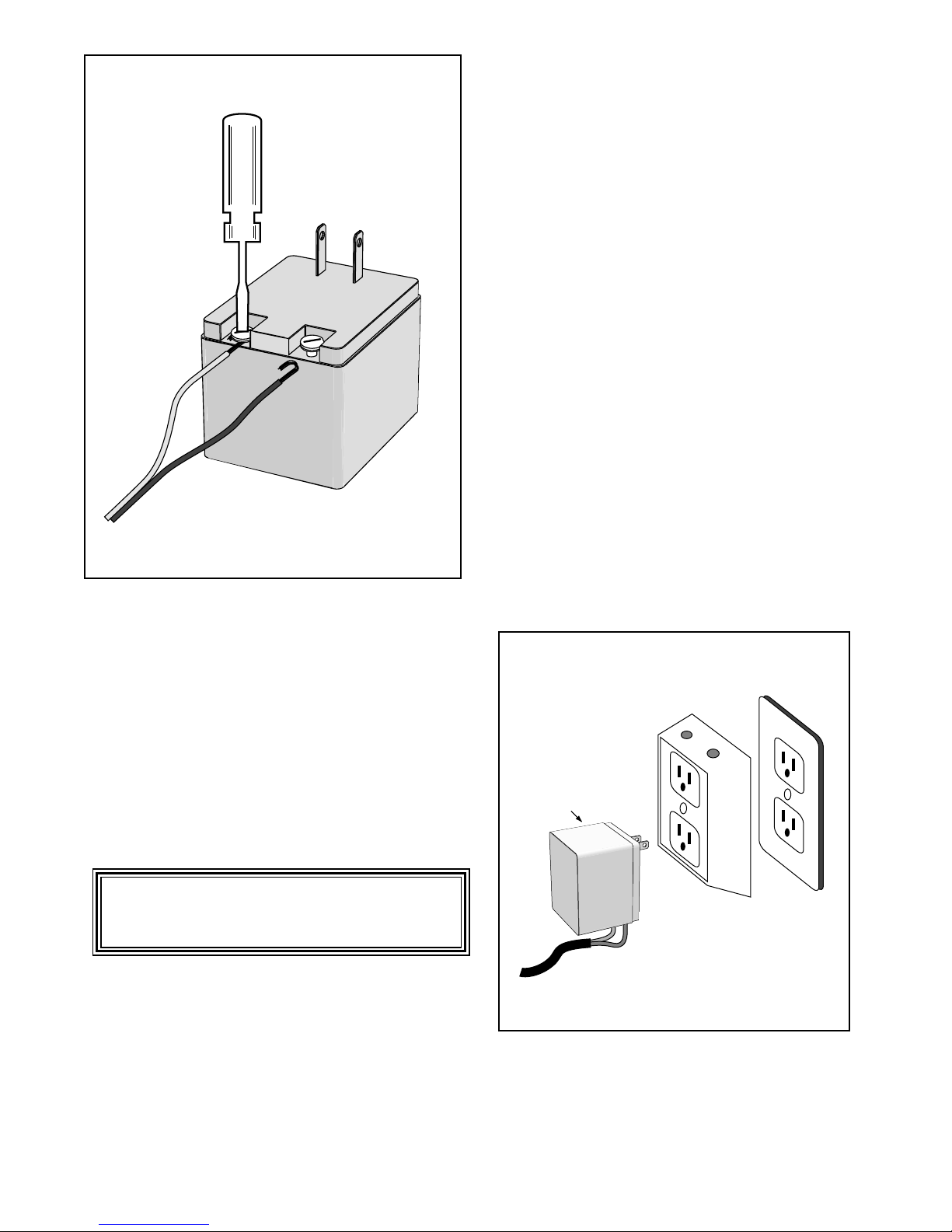
Step 6
SURGE PROTECTOR
Transformer
1
Strip
/2" of insulation from the ends of the low voltage
wire. Attach these stripped ends to the transformer
terminals.
A dab of household petroleum jelly on each terminal will
help prevent corrosion.
Make sure the exposed wires do not touch each other!
Step 7
Plug the transformer into the electrical outlet.
(Use of a surge protector with the transformer is strongly
recommended.)
HINT: Keep a few mothballs in the control box to
discourage insects from entering it and damaging the
control board.
21
Page 26
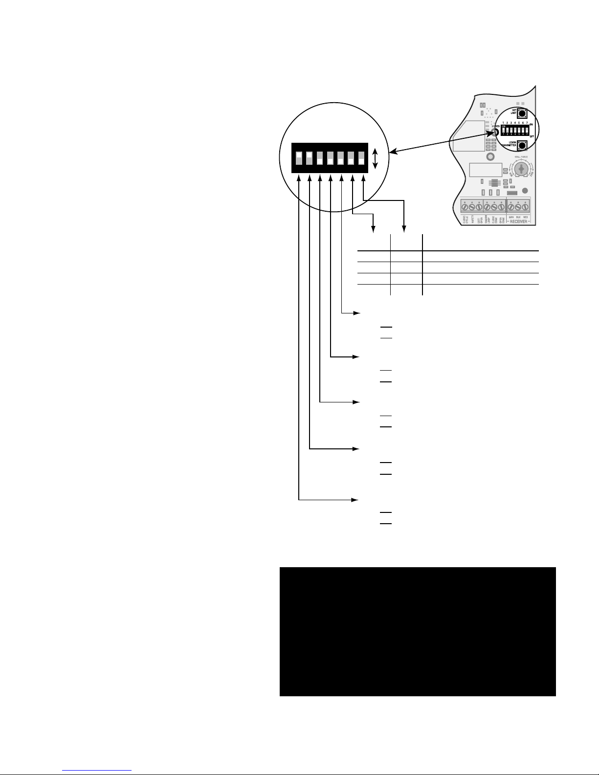
1ON2 3 4 5 6 7
ON
OFF
1 2 3 4 5 6 7
DIP#6 DIP#7 Delay Time for Auto-Close
ON ON 15 seconds
ON OFF 30 seconds
OFF ON 60 seconds
OFF* OFF* 120 seconds (factory preset)
DIP#5
ON
D1 mode, constant pressure to operate gate.
OFF*
B2 mode, momentary contact to operate gate.
DIP#4
ON Push-to-open operation.
OFF* Pull-to-open operation.
DIP#3
ON Auto-close enabled.
OFF* Auto-close disabled.
DIP#2
ON* Buzzer warning enabled.
OFF Buzzer warning disabled
DIP#1
ON* Soft start enabled.
OFF Soft start disabled.
* Factory preset
Control Board Settings
DIP Switches
Main DIP Switch Settings (MODES)
DIP Switch #1 - Soft Start/Stop
The Soft Start/Stop feature slowly starts the
gate as it begins to open and slows the gate as
it comes to the closed position. This saves wear
and tear on the gate and gate operator system.
DIP Switch #2 - Warning Buzzer
The Warning Buzzer alerts you when the gate
operator is beginning to either open or close the
gate. It sounds for the first 2 seconds in each
direction. It also sounds a warning when the gate
obstructs two times in one cycle. Switching this
to OFF only disables the open and close warning
not the obstruction warning.
DIP Switch #3 - Auto-Close
With the Auto-Close switch in the OFF position
the gate will remain open until it receives
another signal from an activation device such
as a transmitter, keypad, or push button control.
With the Auto-Close switch in the ON position
the gate operator will automatically close the
gate. The time the gate will remain open is
determined using DIP Switches #6 and #7.
DIP Switch #4 - Push/Pull-to-Open
If your gate opens into the property the DIP
Switch is set to OFF (factory). If your gate
opens out from the property the DIP Switch
must be set to the ON position. NOTE: if you
have a Push-to-Open gate application you will
need a Push-to-Open bracket (see Push-to-Open
Instructions on page 30).
DIP Switch #5 - B2/D1 Mode
This DIP Switch must remain in the OFF
position unless the gate operator is going to be
used by a guard or gate attendant, who can only
open the gate when constant pressure is applied
to a push button control device.
DIP Switches #6 and #7
The combination of these two switches
determines the amount of time the gate will
remain open when DIP Switch #3 is set in the
ON position.
IMPORTANT CONTROL BOARD SETTINGS:
CONTROL BOARD DIP SWITCH #1 is factory
preset in the ON position and MUST remain in the
ON position. Changing this setting can damage
your gate, gate opener and
possibly void your warranty!
22
Page 27
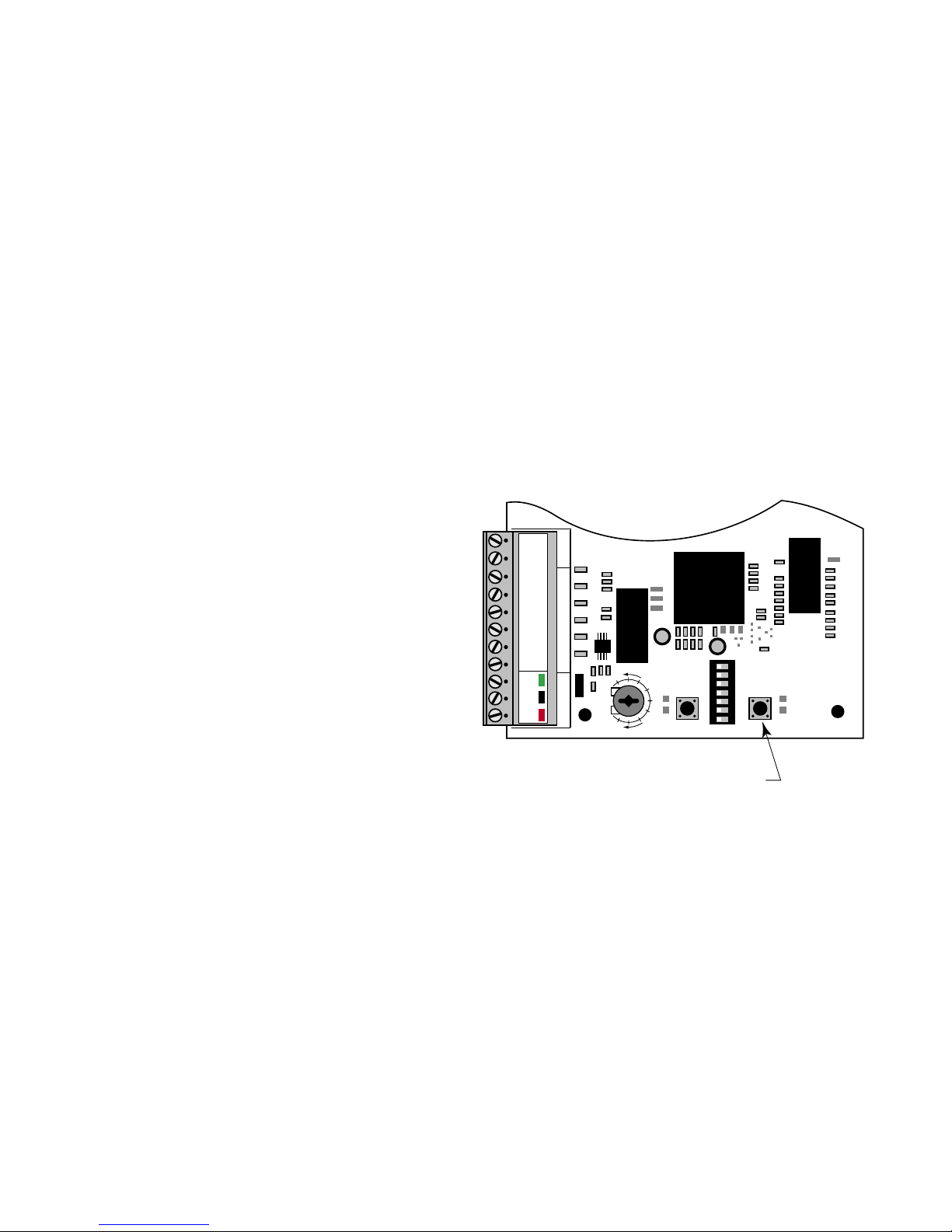
Setting the Closed Position Limit
1
ON
2 3 4 5 6 7
SET
LIMIT
LEARN
TRANSMIT
TER
MODES
ON
OFF
1 2 3 4 5 6 7
Set Limit Button
STALL FORCE
M
I
N
M
A
X
GRN
BLK
RED
RECEIVER
COM COM
CYCLE
CLOSE
SAFETY
EXI
T
OPEN
SHADOW
LOOP
CLOSE
EDGE
OPEN
EDGE
J11
J8
J12
TURN CONTROL BOX ON
Your GTO/PRO® 3000 has two Limit Settings
1) OPEN Limit setting: (Gate in the OPEN POSITION / FACTORY SET NOT ADJUSTABLE) The open limit setting is
the fully open position.
2) CLOSED Limit setting: (Gate in the CLOSED POSITION) To achieve optimum closed position, you are required
to complete the following FOUR STEPS:
Step 1
Confirm that the power switch is in the ON position, and the gate is in the OPEN POSITION.
Step 2
Activate your operator by pressing the entry transmitter
button. Your gate should now be moving from the fully
open position toward the closed position. Prepare to
STOP the gate by pressing the entry transmitter button
again when the gate reaches the desired closed position.
This step may be repeated until desired close position is
achieved. Once the desired CLOSED position has been
achieved, proceed to step 3.
Step 3
With the gate in the desired closed position PRESS &
HOLD the “SET LIMIT" button on the control board for
5 seconds.
Step 4
Press the transmitter button and allow the gate to return
to the fully open position. YOUR GATE’S CLOSED
POSITION LIMIT IS NOW PROGRAMMED.
TESTING YOUR CLOSED LIMIT SETTING:
Press your entry transmitter and allow your gate to close. If CLOSED position is not correct or needs to be changed, you will
need to CLEAR your CLOSED LIMIT settings and follow Steps 1-4 again.
CLEARING THE PROGRAMMED CLOSED LIMIT SETTING:
If you make a mistake and set the limit at the wrong position – press your transmitter to return the gate to the fully opened
position, then press and hold the "SET LIMIT" button for 10 seconds. This will clear the memory for the closed limit
position. Follow Steps 1-4 again.
23
Page 28

Obstruction Sensitivity Potentiometer
STALL FORCE
M
I
N
M
A
X
SET
LIMIT
LEARN
TRANSMITTER
1ON2 3 4 5 6 7
MODES
ON
OFF
1 2 3 4 5 6 7
1ON2 3 4
DUAL
MODES
ON
OFF
1 2 3 4
STALL FORCE
M
I
N
M
A
X
GRN
BLK
RED
RECEIVER
COM COM
CYCLE
CLOSE
SAFETY
EXI
T
OPEN
SHADOW
LOOP
CLOSE
EDGE
OPEN
EDGE
J11
J8
J12
IMPORTANT: For safety reasons the obstruction setting or Stall Force on the GTO/PRO®
3000 control board comes from the factory set at
MIN (minimum). In many gate installations this
setting will need to be adjusted to overcome the
weight and size of the gates.
The Stall Force potentiometer on the control
board operates like a volume control on a radio. It
controls the obstruction sensitivity (or the amount
of force the operator will apply to an obstruction)
before it automatically stops and reverses direction for approximately 2 seconds.
Use a small slotted screwdriver to turn the arrow
in the center of the potentiometer. Adjust the sensitivity from the MINIMUM position where the
gates operate without obstructing from there own
weight or the wind conditions in your area.
NOTE: You may need to increase the
stall force in cold weather due to increased
resistance from gate hinges.
ALWAYS KEEP SAFETY AT THE TOP OF YOUR LIST WHEN ADJUSTING OR
SERVICING YOUR AUTOMATIC GATE OPERATOR!
24
Page 29

Setting Your Personal Transmitter Code
1
ON
2 3 4 5 6 7
SET
LIMIT
LEARN
TRANSMIT
TER
MODES
ON
OFF
1 2 3 4 5 6 7
Learn Transmitter Button
STALL FORCE
M
I
N
M
A
X
GRN
BLK
RED
RECEIVER
COM COM
CYCLE
CLOSE
SAFETY
EXI
T
OPEN
SHADOW
LOOP
CLOSE
EDGE
OPEN
EDGE
J11
J8
J12
All GTO transmitters are set to a standard code at the factory and are ready to operate your GTO/PRO® 3000 Gate
Operator®. For your safety and security, however, we strongly recommend that you replace the factory setting with your own
personal code. Follow the directions below:
1. Remove the Transmitter Cover
Grasp the sides of the access cover and slide it away from the transmitter button (see
illustration). When the access cover is removed, the battery and the DIP switches will be
exposed. To set a new code, use a small screwdriver to move the switches.
2. Set the transmitter DIP Switches
There are nine (9) transmitter DIP switches; each can be placed in three different
positions (+, 0, –). DO NOT set all the switches in the same position, such as all +, all
0, or all –. Once the DIP switches have been set to a personal code, replace and close
the access cover.
WARNING: No other adjustments should be made inside the transmitter.
3. “Teach” the New Code to Control Board Memory
A. Press and hold transmitter button.
B. Press and hold the LEARN TRANSMITTER
button on the control board for 5 seconds.
C. Release transmitter button.
D. Release LEARN TRANSMITTER button.
The new code is stored in control board memory.
25
Page 30
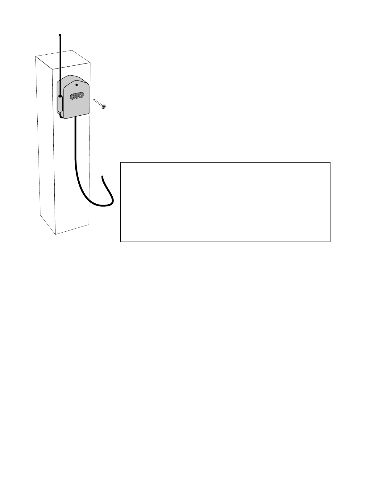
Installing the Receiver
Use the transmitter to check the range of the receiver before permanently mounting it.
Consider the following when mounting the receiver:
• Standard receiver cable length is 10 feet (receivers with a longer cable are available as
special order items; call the GTO Sales Department). NEVER splice receiver cable!
• Run the cable through PVC conduit to protect it from damage.
• DO NOT run cable through metal conduit because the receiver signal range will be
decreased.
• DO NOT run cable in conduit containing ac wiring.
• DO NOT mount receiver on a metal fence or post; doing so will decrease signal range.
• The receiver range can vary from 50 to 100 feet depending upon weather, topography,
and external interference.
NOTE: Do not mount upside down.
FCC Regulation
This device complies with FCC rules Part 15. Operation is subject to the following
conditions:
1. This device may not cause harmful interference.
2. This device must accept an interference that may cause undesired operation.
Transmitter distance may vary due to circumstances beyond our control. NOTE:
The manufacturer is not responsible for any radio or TV interference caused by
unauthorized modifications to this equipment. Such modifications could void the
user’s authority to operate the equipment.
26
Page 31
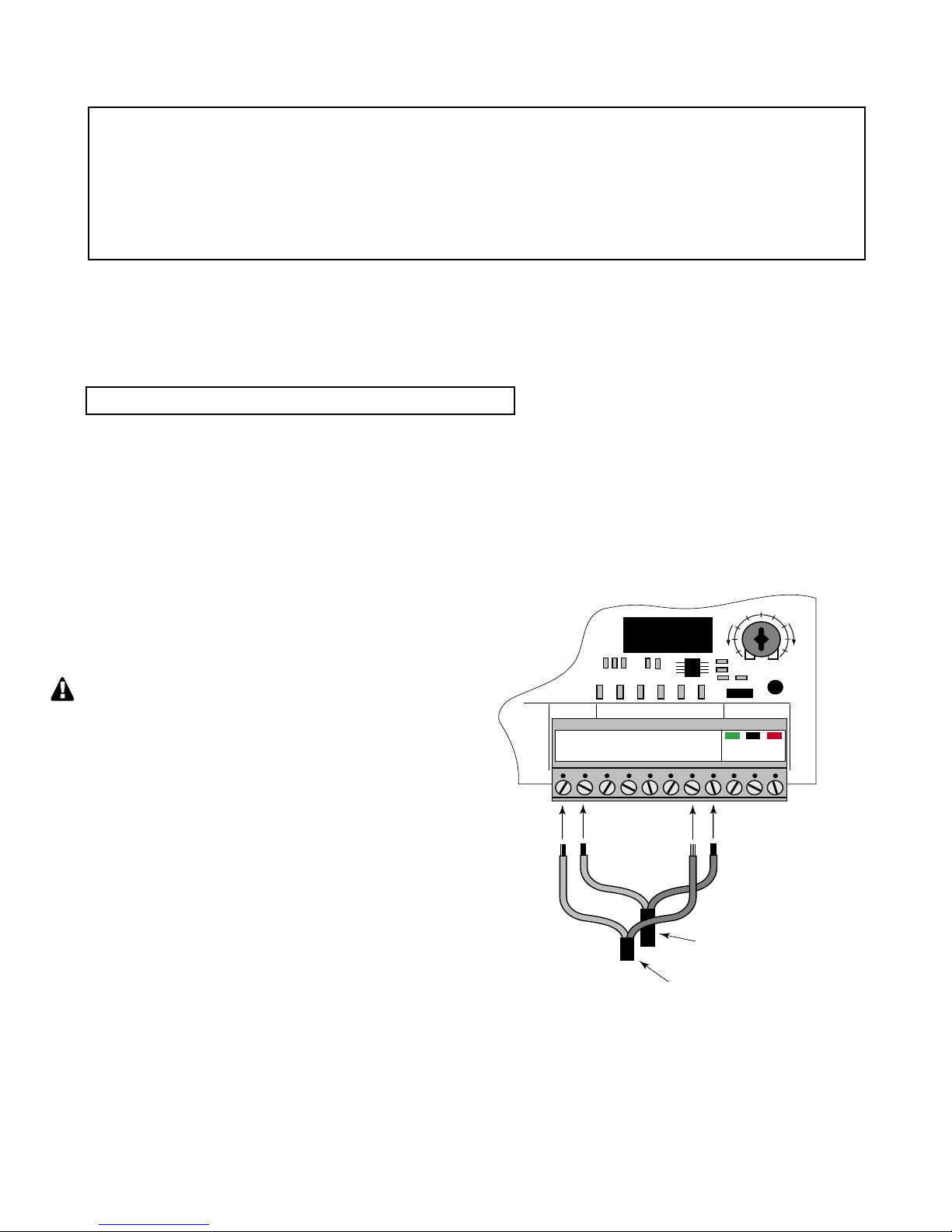
Connecting Additional Safety Devices
Wire from Contact Sensor
(open safety edge)
Wire from Contact Sensor
(close safety edge)
STALL FORCE
M
I
N
M
A
X
GRN
BLK
RED
RECEIVER
COM COM
CYCLE
CLOSE
SAFETY
EXIT
OPEN
SHADOW
LOO
P
CLOSE
EDGE
OPEN
EDGE
J11
J8
J12
Although GTO strongly recommends the use of additional safety devices, we do not endorse any
specific brand names. Only use products that are certified and listed to be in compliance with
any applicable UL standards (United Laboratories) and national and regional safety codes.
Call GTO Sales at 1-800-543-4283 for information on compatible
products for your specific application.
The GTO/PRO® 3000 will ONLY accept accessory devices with normally open contact output.
Contact Sensors (safety edges)
If not installing a contact sensor skip to next section.
PLEASE NOTE: Contact sensors are not included with the GTO/PRO® 3000.
The GTO/PRO® 3000 is equipped with built-in obstruction sensitivity. The operator is designed to stop and reverse the
gate within 2 seconds when it comes in contact with an obstruction. However, obstruction sensitivity, although functioning
properly, may not be sensitive enough to prevent bodily injury in some circumstances. To augment your protection against
entrapment, GTO recommends using some form of additional safety device. When installed, contact sensors must be
mounted in compliance with UL 325, Underwriters Laboratories safety standard for gate operators. Review page 5 for information about mounting requirements for safety edges ("contact sensors").
Refer to the sensor manufacturer’s instructions for
information about installing these devices on a vehicular
gate.
Make sure the power switch to the operator
is turned off before connecting safety device
wiring to the terminal blocks. Unplugging the
transformer does not turn power to the operator
OFF.
Contact Sensor Input Connection:
Connect one of the OPEN EDGE contact sensor wires to the
COMMON (COM) terminal and the other to the OPEN
EDGE terminal on the GTO/PRO® 3000 control board.
Connect one of the CLOSE EDGE contact sensor wires to the
COMMON (COM) terminal and the other to the CLOSE
EDGE terminal on the GTO/PRO® 3000 control board.
Activation of a contact sensor while the gate is in
motion will cause the gate to stop and reverse
within two (2) seconds.
27
Page 32
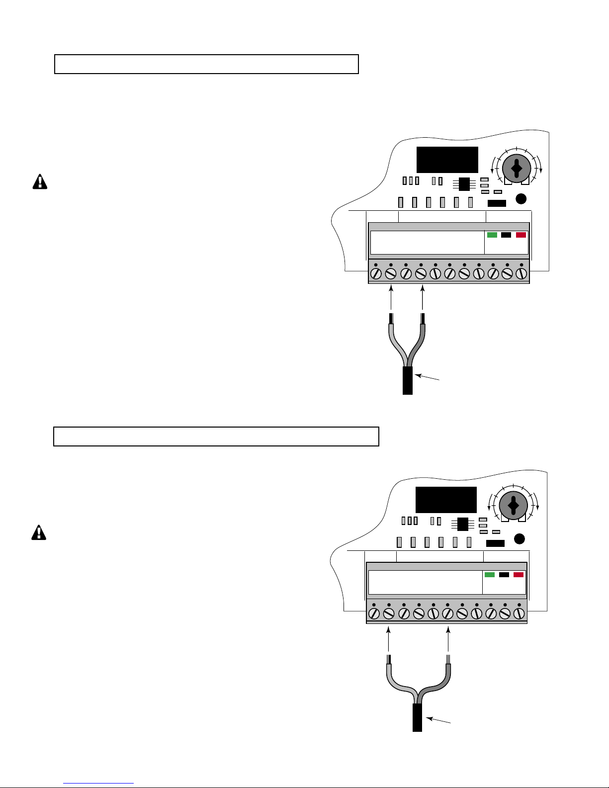
Non-Contact Sensors (photo beams)
Wire from Non-Contact
Sensor (photo beam)
STALL FORCE
M
I
N
M
A
X
GRN
BLK
RED
RECEIVER
COM COM
CYCLE
CLOS
E
SAFETY
EXIT
OPEN
SHADO
W
LOOP
CLOSE
EDGE
OPEN
EDGE
J11
J8
J12
Wire from Shadow Loop
STALL FORCE
M
I
N
M
A
X
GRN
BLK
RED
RECEIVER
COM COM
CYCLE
CLOSE
SAFETY
EXIT
OPEN
SHADOW
LOOP
CLOSE
EDGE
OPEN
EDG
E
J11
J8
J12
If not installing a non-contact sensor skip to next section.
PLEASE NOTE: Non-contact sensors are not included with the GTO/PRO® 3000.
The GTO/PRO® 3000 can also accept "Safety" input from normally open "dry-contact" output devices such as photo beams
connected to the SAFETY input terminal.
Refer to the sensor manufacturer’s instructions for information
about installing these devices on a vehicular gate.
Make sure the power switch to the operator is
turned off before connecting safety device wiring
to the terminal blocks. Unplugging the transformer
does not turn power to the operator OFF.
Non-Contact Sensor Connection:
Connect one of the non-contact sensor dry contact output wires to
the COMMON (COM) terminal and the other to the SAFETY
terminal on the GTO/PRO® 3000 control board.
This input is ONLY monitored when the gate
is closing. Activating the non-contact sensor
(obstructing the safety beam path) will cause the
gate to reverse to the fully open position.
Shadow Loop
If not installing a shadow loop skip to next section.
PLEASE NOTE: Non-contact sensors are not included with the GTO/PRO® 3000.
Refer to the sensor manufacturer’s instructions for information
about installing these devices on a vehicular gate.
Make sure the power switch to the operator is
turned off before connecting safety device wiring
to the terminal blocks. Unplugging the transformer
does not turn power to the operator OFF.
Shadow Loop Connection:
Connect one of the shadow loop wires to the COMMON (COM)
terminal and the other to the SHADOW LOOP terminal on the
GTO/PRO® 3000 control board.
The shadow loop is a detector located with the moving path of the
gate to prevent the gate from closing when a vehicle in the path.
28
Page 33
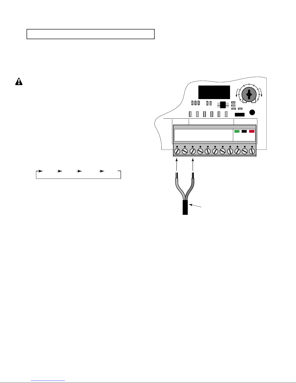
Connecting Accessories
OPEN STOP CLOSE STOP
Wire from Accessory
(push button, key pad, etc.)
STALL FORCE
M
I
N
M
A
X
GRN
BLK
RED
RECEIVER
COM COM
CYCLE
CLOSE
SAFETY
EXIT
OPEN
SHADOW
LOOP
CLOSE
EDGE
OPEN
EDGE
J11
J8
J12
If not connecting accessories skip to next section.
The GTO/PRO® 3000 can accept NORMALLY OPEN CONTACT accessories, such as; Push Button Entry Devices and
Key Pads.
Refer to the sensor manufacturer’s instructions for information about installing these devices on a vehicular gate.
Make sure the power to the operator is turned
off before connecting safety device wiring to the
terminal blocks. Unplugging the transformer
does not turn power to the operator OFF.
Accessory Input Connection:
Connect one of the accessory wires to the COMMON (COM)
terminal and the other to the CYCLE CLOSE terminal on the
GTO/PRO® 3000 control board.
Each activation of the accessory will cause the
gate to cycle as follows:
Output Relay
The output relay provides N/O and N/C contact. N/O contact
functions only when gate is moving. N/C contact functions only
when gate is at rest. Relay can switch up to 36 volts A/C or D/C
and can be used for strobe type warning lights, to turn on safety
beams, etc.
29
Page 34
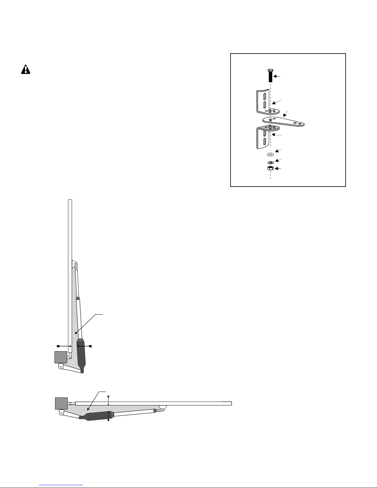
Gate in the Closed Position
Pinch Area (gray)
Gate in the Open Position
Pinch Area (gray)
Two inch minimum
Two inch minimum
Push to Open Installation
3/8" x 2" Bolt
3/8" Nut
Post Pivot Bracket
Post Bracket
Post Bracket
3/8" Lock Washer
Post Bracket Assembly
3/8" Washer
Determining The Mounting Position
of The Post Bracket Assembly
Swinging gates shall not open into public access areas!
A "Push-to-Open" gate opens out from the property.
A Push-to-Open Bracket is required for this type of installation (see
Accessory Catalog). If you have a pull-to-open gate (gate opens into the
property), return to page 13; step 3.
In a PUSH-TO-OPEN installation the operators are installed while the gates
are in the closed position.
Step 1
With the gates closed, adjust the post bracket assembly and the gate
bracket until the operator is level. While holding the operator level,
use C-clamps to temporarily keep the post bracket assembly and
gate bracket in their respective positions on the fence post and gate.
IMPORTANT: While determining the mounting point for the post
pivot bracket assembly be sure that the position allows for maximum
clearance between the gate and the operator in both the open and closed
positions, as shown in the diagrams below. This clearance will give the
operator the most efficient leverage point for opening and closing the
gate and more importantly provides the least possible pinch area.
Step 2
After verifying that you have the best position
for the post pivot bracket, insert the 5/16" x 1 3/4"
bolt through the aligned holes of the post bracket
and post pivot bracket and fasten it with the 5/16"
washer and nut.
IMPORTANT: If you loosened the clamp on
the post bracket to achieve the optimum position,
tighten it in its new position and recheck the gate
bracket with the gate in the open position (move the
gate bracket and re-clamp it if necessary).
30
Page 35
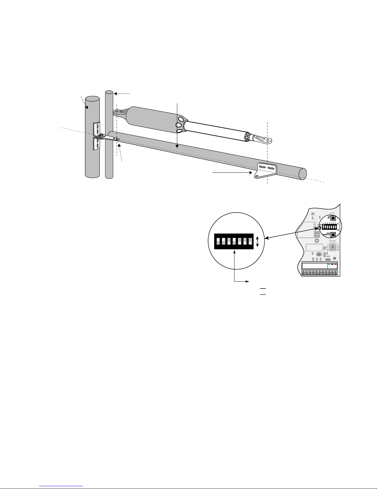
1ON2 3 4 5 6 7
ON
OFF
1 2 3 4 5 6 7
DIP#4
ON Push-to-open operation.
OFF Pull-to-open operation (factory setting).
GRN
BLK
RED
RECEIVER
COM COM
CYCLE
CLOSE
SAFETY
EXIT
OPEN
SHADOW
LOO
P
CLOSE
EDGE
OPEN
EDGE
Step 3
Operator
Fence Post
Gate Post and Gate Cross Member
(In Closed Position)
POST PIVOT BRACKET level with the
horizontal surface of the GATE BRACKET
LEVEL
LEVEL
LEVEL
With the gate in the fully closed position and the operator retracted, swing the operator to the gate. Mark reference points for
bolt holes on gate cross member through middle of gate bracket slots. The operator must be level. (Some vertical adjustment
is possible by sliding the post bracket assembly up and down.) Drill 3/8" holes into the gate cross member as marked. Fasten
gate bracket to cross member using (2) 3/8" x 3" bolts, washers, lock washers, and nuts. Attach the operator to the post
bracket assembly and gate bracket using clevis pins, bushings, and hairpins clips.
Step 4
Make sure the control box power switch is OFF. Use a small
screwdriver to move the Number 4 DIP switch from the factory
setting (OFF / Pull-To-Open) to ON for Push-To-Open. Turn
power switch ON. The control board is now configured to push
the gate open.
Setting the Open Position Limit
Step 1
Confirm that the power switch is in the ON position, and the gate is in the CLOSED POSITION.
Step 2
Activate your operator by pressing the entry transmitter button. Your gate should now be moving from the closed position
toward the open position. Prepare to STOP gate by pressing the entry transmitter button again when the gate reaches the
desired open position. This step may be repeated until desired close position is achieved. Once the desired OPEN position has
been achieved, proceed to Step 3.
31
Page 36

Step 3
1
ON
2 3 4 5 6 7
SET
LIMIT
LEARN
TRANSMIT
TER
MODES
ON
OFF
1 2 3 4 5 6 7
Set Limit Button
STALL FORCE
M
I
N
M
A
X
GRN
BLK
RED
RECEIVER
COM COM
CYCLE
CLOSE
SAFETY
EXI
T
OPEN
SHADOW
LOOP
CLOSE
EDGE
OPEN
EDGE
J11
J8
J12
With the gate in the desired open position PRESS & HOLD the “SET LIMIT"
button on the control board for 5 seconds.
Step 4
Press the transmitter button and allow the gate to return to the closed position.
YOUR GATE’S OPEN POSITION LIMIT IS NOW PROGRAMMED.
TESTING YOUR OPEN LIMIT SETTING:
Press your entry transmitter and allow your gate to open. If the OPEN position
is not correct or need to be changed, you will need to CLEAR your OPEN
LIMIT settings and follow steps one (1) to four (4) again.
CLEARING PROGRAMMED OPEN LIMIT SETTING:
If you make a mistake and set the limit at the wrong position – press your
transmitter to return the gate to the closed position, then press and hold the
"SET LIMIT" button for 10 seconds. This will clear the memory for the open
limit position. Follow steps one (1) to four (4) again.
32
Page 37

Maintenance & Troubleshooting Guide
If your gate operator does not function properly after it is installed, use this guide
before calling the GTO Service Department.
• On all gates weighing 250 lb. or more, routinely grease the ball bearing hinges at least 4 times a year; more
frequently if the gates are near a coastal area.
• Keeping a few mothballs in the control box will discourage insects from entering it and damaging the control
board.
• Clean the push-pull tube with a soft, dry cloth and apply silicone spray to it at least once per month.
• While oxidation is a normal part of weathering of equipment that is exposed to the elements, we recommend
you apply silicone spray the front and rear mounts to minimize this effect.
If the Operator Does Not Work
Check the Green LED on the Control Board:
IF THE LED IS OFF: This condition indicates a transformer power failure.
1. Test the transformer for voltage with a voltmeter. The acceptable range can be found in the VOLTAGE
LIMITS chart on the next page. If the transformer test shows no voltage, then test the electrical outlet for
voltage. If the outlet test shows voltage, then the transformer is dead and must be replaced. Allow the new
transformer 12 hours to charge the battery before using the gate operator.
2. If the transformer test shows voltage, check the POWER IN terminal block on the control board for voltage.
If the terminal block shows no voltage, look for broken or spliced wires.
Check the Red STATUS LED on the Control Board:
IF THE LED IS ON: but the unit is not working.
1. Check the battery in your transmitter and replace with a fresh one if needed..
2. Verify that the power cable is securely connected.
3. Replace the control board fuse if it is blown (25 ampere fuse only - DO NOT USE
A HIGHER RATED FUSE!).
IF THE LED IS OFF:
1. Make sure the ON / OFF switch at the bottom of the control box is set to ON.
2. Check all connections for looseness and corrosion.
33
Page 38

If the Operator is Working
PROFESSIONAL ACCESS SYSTEMS
®
The Gate CLOSES Then Opens Again on its Own:
1. Check the position of the mounting brackets and readjust if necessary.
2. Check the gate for binding or hinge damage.
The Gate OPENS Then Closes Again on its Own:
1. Check the position of the mounting brackets and readjust if necessary.
2. Check the gate for binding or hinge damage.
VOLTAGE RATINGS
18 Vac Transformer ___________________________ 18.0 to 22.0 Vac
5 W Solar panel (single) _______________________18.0 to 22.0 Vdc 300 mA
measure voltage at panel and control box.
12 V Battery ________________________________12.0 to 13.5 Vdc 7.0 Ah
Charging circuit _____________________________12.0 to 14.8 Vdc
measure voltage with battery connected
The GTO, Inc. Technical Service Department is open
Monday – Friday 8:00 A.M. – 5:00 P.M. (Eastern Time)
Telephone (800) 543-1236
Telephone (850) 575-4144
Fax (850) 575-8950 • Web site: www.gtopro.com wwww.gtopro
34
Page 39

Repair Service
PROFESSIONAL ACCESS SYSTEMS
®
If your GTO/PRO® 3000 ® Gate Operator is not operating properly, please follow the steps below:
1. First use the procedures found in the Maintenance & Troubleshooting Guide (see page 33).
2. If you are unable to solve the problem, call the GTO Service Department at (800) 543-1236, or (850) 575-4144.
Refer to the serial number (located on the control box cover) and date of purchase when calling for assistance.
3. If repair or replacement of your gate operator is necessary, the Service Department will assign a Return Goods
Authorization (RGA) number to you.
4. Securely pack the component(s) authorized for return to the factory. Write the RGA number issued to you on the outside
of the package in LARGE BOLD PRINT. Ship the package(s) freight prepaid to:
GTO, Inc., 3121 Hartsfield Road, Tallahassee, Florida, USA 32303.
NOTE: Products returned to GTO without a Return Goods Authorization (RGA) number in LARGE
BOLD PRINT on the outside of the package WILL NOT be accepted. Also, items returned to GTO freight
collect WILL NOT be accepted.
Fax (850) 575-8950 • Web site: www.gtopro.com
E-Mail: [email protected]
GTO, Inc.
3121 Hartsfield Road • Tallahassee, Florida, USA 32303 • (850) 575-0176 • Fax (850) 575-8912 •
Web site www.gtopro.com
35
Page 40

Column Installation Information
Column
Po
st Bracket
pivot point
Gate
A
B
Column Mount Example
(A + B can not exceed 14 inches)
Example: If A is 2" then B can not exceed 12"
Hinge
IF THIS OPERATOR WILL BE USED WITH GATES THAT ARE MOUNTED ON
MASONRY, BRICK, OR ROCK (etc.) COLUMNS:
READ THE FOLLOWING CAREFULLY BEFORE PROCEEDING
A. The simplest solution is to install the operator in a push-to-open configuration (requires Push-To-Open Bracket,
see Accessory Catalog). The minimum clearance is easier to achieve and clearance is no longer a problem,
since the operator will be pushing the gate away from the column instead of pulling it toward the column. It
is recommended that you place a steel plate between the operator mounting brackets and masonry surface for
additional strength.
B. If a push-to-open installation is impossible due to traffic hazards, terrain, etc., another option is to re-hang the
gate. You may hang it on a post, either in the center of the column or at the back corner, or move the gate to the
back corner of the columns.
C. The most difficult solution is to cut a notch in the column to accommodate the operator and power cable. This
job is NOT for the inexperienced!
36
Page 41
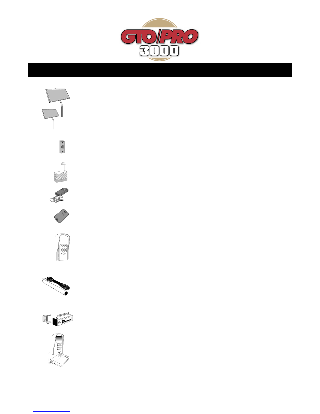
ACCESSORIES
®
DC-SERIES
AUTOMATIC
G
ATE
L
OCK
®
ELECTRO
NIC SEC
URITY
L
OCK
1
2
ABC
3
DEF
4
GHI
5
JKL
6
MNO
7
PRS
8
TUV
9
WXY
0
POW
E
R
K
e
y
p
a
d
B
a
t
t Lo
w
Gran
t
Perm
i
ssio
n
An
s
w
er
D
V
9V
A
CC
ES
S CONTR
OL
S
YS
T
E
MS
1-
80
0
-5
4
3
-
4
2
8
3
Solar Panel (FM123), (FM122)
The Solar Panel is a 10 watt solar powered battery charger for use with the all GTO/PRO DC gate
operator systems. Particularly suited for remote installations, each Solar Panel comes with tubular
steel support, mounting clips, wire connectors, and 8 ft. of low voltage wire (see Low Voltage Wire
for additional wire). The GTO/PRO® control board has clearly labeled terminal connections for easy
installation of the Solar Panel. Installation in some regions of the world will require multiple solar
panels for adequate charging power. Solar Panel (FM122) is a 5 watt solar powered battery
charger with all the same features as (FM123).
Push Button Control (RB101)
Unlit doorbell button for remote entry or exit control. Wires directly to the control board and uses 16
gauge multi-stranded, dual conductor low voltage wire (sold separately).
Pin Lock (RB975)
The Pin Lock substitutes for the clevis pin at the front end of the GTO/PRO® 1500 gate operator.
Helps prevent theft of the operator from the gate, while allowing quick release of the operator.
Key Chain Mini Transmitter (RB744)
The Key Chain Mini Transmitter is a miniature version of the GTO/PRO® entry transmitter and has
the same adjustable code settings. 12 Volt battery included.
Entry Transmitter (RB741)
The GTO/PRO® entry transmitter, with adjustable code settings, is standard equipment with all
GTO/PRO® systems. 9 Volt battery included.
Digital Keypad (F300)
The specially designed digital keypad can be easily installed as a wireless or wired keypad. It can be
programmed to use up to fifteen different personal identification number (PIN) codes. Each code is
face programmable with additional security features built in. Wired installations require 16 gauge, low
voltage, multi-stranded, dual conductor, direct burial wire (sold separately). Requires 3 AA batteries
(not included).
GTO/PRO 50' Exit Wand (FM139), 100' Exit Wand (FM140), 150' Exit Wand (FM141)
The GTO/PRO® Exit Wand is designed for residential and agricultural applications and is
compatible with all GTO/PRO® automatic gate operator models. The wand is an electromagnetic
sensor, which offers 'hands free' operation of the GTO/PRO® Gate Operators with a 12 ft. radius of
detection of vehicles in motion.
Automatic Gate Lock Pull-to-Open (FM144)
A MUST for added security. Solenoid driven, with a steel housing. Unlocks and locks automatically
as gates open and close. Used with GTO/PRO® DC swing gate operating systems for maximum
stability and security. Comes with a keyed manual release. Recommended for gates over 8 ft. long.
Ideal for animal enclosures or high wind areas.
Wireless Entry Intercom / Keypad (FM136)
Allows owner to screen guest at the gate before allowing access to the property. Keypad also allows
owner to give up to 25 programmable entry codes to family, friends or approved delivery personnel.
Codes can be permanent of temporary. Can be wireless or hard wired up to 1000 feet.
37
Page 42
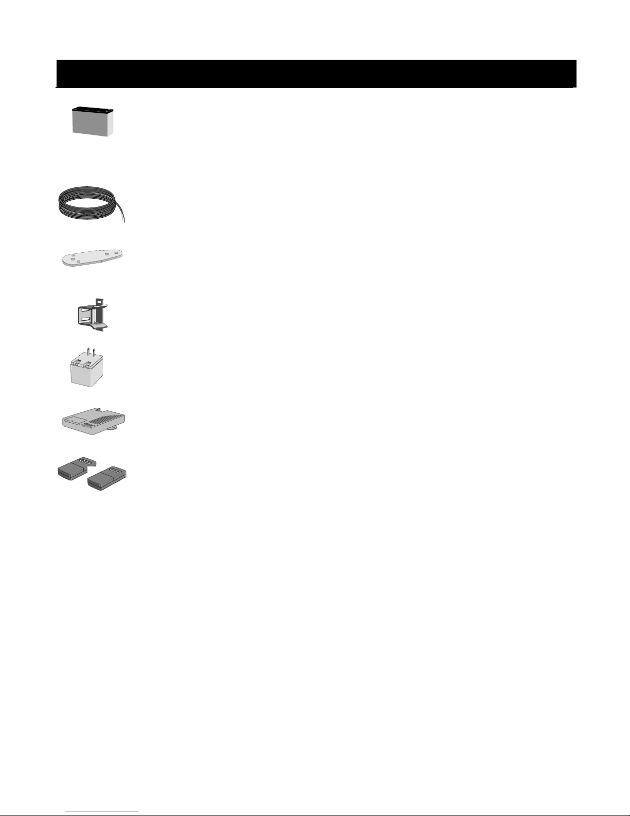
HEDDOLF
UNIVERSAL
RECEIVER
MODEL 294
ACCESSORIES
Replacement Battery (RB500)
Standard 12 volt, 7.0 amp-hour, maintenance-free battery for the GTO/PRO® 2000, GTO/PRO® 3000,
GTO/PRO® 4000 gate operator systems. This is the only battery approved for use with the GTO/PRO® gate
operator systems. Life expectancy is 3-5 years.
Low Voltage Wire (RB509)
The 16 gauge, multi-stranded, dual conductor Low Voltage Wire is for connecting the AC powered
transformer, or the Solar Panel to the control board. Also used for the connection of accessories, such as locks,
keypads, push buttons and other wired control devices. This specially designed wire is UV treated, PVC coated
and ready for direct burial. Available in 1000' rolls or special lengths.
Push to Open Bracket (347 IH)
Required when GTO/PRO® 3000 gate operator(s) must push the gate open, such as on a sloping driveway or where
space prevents gate(s) from opening inward (pulled open). Order two PTO brackets for conversion of a dual swing
gate installation.
Column Mount Lock Receiver (433IH)
For mounting the Automatic Gate Lock on brick columns, walls, or for other applications with limited space
between gate and post.
Replacement Transformer (RB570)
Standard 18 volt AC transformer for maintaining the battery included with the GTO/PRO® 3200 gate operator. This
is the only transformer approved for use with all UL325 GTO/PRO® gate operator systems.
Garage Door Receiver (RB709)
The Garage Door Receiver allows you to use the same GTO/PRO® entry transmitter (see Dual and Triple
Transmitters) to operate your gate operator and your garage door operator. Compatible with most garage door
operators.
Dual & Triple Button Transmitters (RB742 & RB743)
The Dual (RB742) & Triple (RB743) Button Transmitters are for remote control of multiple separate gate operators,
and/or gate operator(s) and garage door operator(s) (see Garage Door Receiver). 9 Volt battery included.
If you have a question about GTO/PRO accessories
just call 1-800-543-GATE!
The contents of all material available on this installation manual are copyrighted by GTO, Inc. (“GTO”), unless otherwise indicated. All rights are reserved by GTO, and content may not be reproduced,
downloaded, disseminated, published, or transferred in any form or by any means, except with the prior, written permission of GTO. Any reprinting of GTO publications is by permission only. Copyright
GTO®, GTO/PRO®, Bulldog® are registered trademarks of GTO, Inc. Professional Access Systems™ is a trademark of GTO, Inc. and are the exclusive property of GTO, Inc. (“GTO”).
All rights are reserved by GTO, and these marks may not be used, in any for without the prior, written permission of GTO.
infringement is a violation of federal law.
38
 Loading...