


INSTALLATION MANUAL

 WARNING
When an EXIT WAND is in use, the automatic gate operator could be activated by a child on a bicycle, tricycle or other metal play equipment. This product is not recommended for applications exposed to children.
If you are installing this product on an AC powered gate operator, we recommend you consult a certified electrician.
Parts Identification:
! WARNING
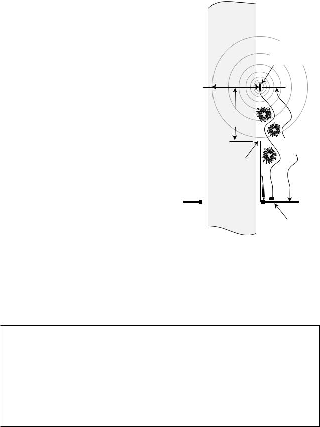
GATE OPENING SENSOR
  IN USE
The Automatic Gate Opener is activated when a vehicle comes within range of the sensor buried along side the driveway and could possibly be activated by a child on a bicycle, tricycle or other metal play equipment.
WAND with 50, 100 or 150 feet of
Direct Burial Cable
|
! |
|
|
W |
|
Double Spade |
ARNING |
|
|
||
Connectors (2) |
|
|
Battery Connection |
Ty-Wraps (4) |
|
Wires (2) |
||
|
Warning Signs (2)
Wire Clamp
Wire Nuts (3) |
Range |
Adjustment Board |
GTO, Inc. • 3121 Hartsfield Road • Tallahassee, Florida 32303 1-800-543-GATE (4283) • www.gtoinc.com
Technical Support (800) 543-1236
RWINSTPRO rev-7/26/06

Thank You ...
for purchasing the GTO/PRO® EXIT WAND. This product requires no maintenance and will give you years of enjoyment by providing hands free operation of your gate. GTO, Inc. has been designing and manufacturing reliable, high quality products since 1987. Our corporate headquarters and state of the art manufacturing facility is located in Tallahassee, Florida. One of our highest priorities is to provide outstanding technical service to our customers. Therefore, if you have any questions or require any technical assistance, please call 800-543-1236 or 850-543-4144 and ask to speak to one of our technicians.
The EXIT WAND you have purchased is designed with some of the most advanced technology available. In layman’s terms, the wand detects a change in the earth’s magnetic field caused by a mass of metal in motion and automatically opens your gate. The range adjustment potentiometer (POT) that connects to the control box provides you with the ability to increase or decrease the wand’s sensitivity range.
If a metal object is placed directly above the wand (with little motion) it may cause the wand to activate, thus opening your gate. For this reason we do not recommend the EXIT WAND in environments exposed to children.
Prior to installing your wand please read the manual thoroughly. There are important safety recommendations of which you should be aware. This product, and any accessory you purchase, should only be installed on a gate operator that meets the current safety standard (UL325). If you have a gate operator that is not listed with the current standards, please contact the GTO Sales Department toll free (800) 543-4283 for consultation on a gate operator that can meet your specific needs.
Joe Kelley, President of GTO, Inc.
Contents
Before You Start ---------------------------------------------------------------------- |
page 1 |
Terms and Definitions: ----------------------------------------------------------- |
page 1 |
How the EXIT WAND Works:-------------------------------------------------- |
page 1 |
How the EXIT WAND’s RANGE ADJUSTMENT Works:----------------- |
page 1 |
Placement of the WAND:-------------------------------------------------------- |
page 2 |
Installation Overview:------------------------------------------------------------ |
page 2 |
Installing the EXIT WAND--------------------------------------------------------- |
page 3 |
Determining WAND Location:-------------------------------------------------- |
page 3 |
Installing the WIRE CLAMP:--------------------------------------------------- |
page 3 |
Wiring the WAND to GTO/PRO Low Voltage Operators:------------------- |
page 4 |
Accessory Terminal Connection------------------------------------------------ |
page 4 |
Connecting the Range Adjustment Control Board: -------------------------- |
page 5 |
Power Supply Connection: ------------------------------------------------------ |
page 5 |
Powering Up the WAND: ------------------------------------------------------- |
page 6 |
Adjusting the Range: ------------------------------------------------------------ |
page 6 |
Wiring the WAND to GTO/PRO AC Powered Operators:------------------- |
page 7 |
Accessory Terminal Connection------------------------------------------------ |
page 7 |
Connecting the Range Adjustment Control Board: -------------------------- |
page 8 |
Power Supply Connections: ---------------------------------------------------- |
page 9 |
Powering Up the WAND:-------------------------------------------------------- |
page 9 |
Adjusting the Range: ------------------------------------------------------------ |
page 9 |
Installation on Other Brand Gate Operators----------------------------------- |
page 10 |
Technical Specifications ------------------------------------------------------------ |
page 11 |
Trouble Shooting --------------------------------------------------------------------- |
page 11 |
Other GTO Products ---------------------------------------------------------------- |
page 12 |

Conversion Chart
Converting Metric Units to English Equivalents
When You Know |
Multiply By |
To Find |
Symbol |
centimeters |
0.3937 |
inches |
in. (or “) |
meters |
3.2808 |
feet |
ft. (or ‘) |
kilograms |
2.2046 |
pounds |
lb. (or #) |
Converting English Units to Metric Equivalents
When You Know |
Multiply By |
To Find |
Symbol |
inches |
2.5400 |
centimeters |
cm |
feet |
0.3048 |
meters |
m |
pounds |
0.4535 |
kilograms |
kg |
Converting Temperature
deg. Celsius |
(ºC x 1.8) + 32 |
deg. Fahrenheit |
ºF |
deg. Fahrenheit |
(ºF-32) ÷ 1.8 |
deg. Celsius |
ºC |
This product and any accessory you purchase should only be installed on a gate operator that meets the current safety standard, UL325, latest edition. If you have a gate operator that is not listed with the current standard please contact the GTO sales department for consultation on a gate operator that can meet your specific needs.
GTO Limited One Year Warranty:
GTO, Inc., gate operators and accessories are warranted by the manufacturer against defects in materials and manufacturer workmanship for a period of one (1) year from date of purchase, provided the recommended installation procedures have been followed.
In the case of product failure due to defective material or manufacturer workmanship within the one (1) year warranty period, the product will be repaired or replaced (at the manufacturer’s option) at no charge to the customer, if returned freight prepaid to GTO, Inc., 3121 Hartsfield Road, Tallahassee, Florida, USA 32303. IMPORTANT: Call (850) 575-4144 or Fax (850) 575-8950 for a Return Goods Authorization (RGA) number before returning accessory to factory. Products received at the factory without an RGA number will not be accepted. Replacement or repaired parts are covered by this warranty for the remainder of the one (1) year warranty period or six (6) months, whichever is greater. GTO, Inc. will pay the shipping charges (equal to United Parcel Service GROUND rate) for return to the owner of items repaired under warranty.
The manufacturer will not be responsible for any charges or damages incurred in the removal of the defective parts for repair, or for the reinstallation of those parts after repair. This warranty shall be considered void if damage to the product(s) was due to improper installation or use, connection to an improper power source, or if damage was caused by lightning, wind, fire, flood, insects or other natural agent.
After the one (1) year warranty period, GTO, Inc. will make any necessary repairs for a nominal fee. Call GTO at (800) 543-1236 for more information. This warranty gives you specific legal rights, and you may also have other rights which may vary from state to state. This warranty is in lieu of all other warranties, expressed or implied. NOTE: Verification of the warranty period requires copies of receipts or other proof of purchase. Please retain these records.
If you have any questions call Technical Support at (800) 543-1236

Before You Start ...
Please read the instructions completely before you begin the installation.
Terms and Definitions:
•METAL OBJECT: anything that is made of iron based metal, from a child’s toy to a car or truck.
•WAND: the magnetic device inside the waterproof tube that detects METAL OBJECTS in motion.
•MAGNETIC FIELD: an area around the WAND where metal in motion can be detected.
•MAGNETIC DISTURBANCE: a change in the MAGNETIC FIELD which lets the WAND know that it needs to send a signal to the gate operator to open the gate.
•RANGE: the distance from the WAND in which a MAGNETIC DISTURBANCE can be detected in the MAGNETIC FIELD.
•RANGE ADJUSTMENT: the RANGE is adjustable from a 3 to 12 foot* radius by tuning the ADJUSTMENT POTENTIOMETER (POT) on the RANGE ADJUSTMENT CONTROL BOARD (shown on page 5). Within this RANGE, the closer you get to the WAND, the less metal and motion an object needs to cause a DISTURBANCE in the MAGNETIC FIELD.
CAUTION This principle explains why a child’s tricycle, bicycle and other metal play equipment moving close to the WAND may have the same DISTURBANCE as a car or truck at a greater distance, and can cause the gate to open.
•WIRE CLAMP: a device which provides a secure and weatherproof opening for the wire from the WAND to be brought into a control box (see Parts Identification on cover).
•DOUBLE SPADE CONNECTOR: a wire connector which allows the connection of two wires to be connected to a single terminal (see Parts Identification on cover).
How the EXIT WAND works:
•When a metal object such as a car, truck or motorcycle in motion disturbs the MAGNETIC FIELD around the WAND, a signal is sent to the automatic gate operator’s control board, signaling it to open the gate.
•The metal object must be in motion to disturb the MAGNETIC FIELD, thus activating the gate operator. A stationary vehicle or object will not disturb the MAGNETIC FIELD.
How the EXIT WAND’s RANGE ADJUSTMENT works:
•The RANGE distance can be adjusted from a 3 to 12 foot* radius from the WAND.
•The potentiometer varies the sensitivity range of the WAND to avoid unwanted moving metal objects from activating the gate operator, such as: other moving gates; metal play equipment; garage doors; other vehicular traffic; etc.
•With the RANGE adjusted to the maximum of 12 feet*, a large metal object moving slowly will be detected 12 feet* from the WAND, while a small metal object moving slowly might not be detected at the same distance. As you move closer toward the WAND, the small moving metal object will at some point cause a DISTURBANCE in the MAGNETIC FIELD and activate the gate operator.
* Range distance is approximate and will vary due to outside interference, type of soil, vehicle mass, speed, etc.
1
Placement of the WAND:
•The WAND comes with 50, 100 or 150 feet of cable. A typical installation will require about 5 feet of wire to come from the ground up and into the control box for connection to the power supply and control board. Check your specific installation for exact dimensions.
•From the point on the ground where you will run the WAND cable into the control box, lay the wire out on a path as far as you can from the control box. The WAND should be no more than two (2) feet from the edge of the driveway and no closer than 25 feet from the end of the open gate.
•The WAND’s RANGE can be adjusted to a maximum of 12 feet*. The movement of a gate in its open position could cause a DISTURBANCE in the MAGNETIC FIELD of the WAND if it comes within the RANGE of the WAND. Make sure the end of the open gate is a minimum of 25 feet from the WAND. If you have a situation where the WAND has to be buried closer than 25 feet you will have to adjust the RANGE of the WAND to compensate for the closeness.
Driveway
WAND:
2 feet from driveway (max)
RANGE: 12 ft. radius (max)
25 ft. from gate (min)
up to 145 ft. of Cable (max)
Open Gate
Outside Sensor Range
Gate Operator
Control Box
Installation Overview:
•Once the best location for the WAND is determined, you are ready to bury the WAND and run the cable underground to the control box. Connect the WAND wires and the RANGE ADJUSTMENT CONTROL BOARD to the gate operator control board and power supply. Adjust the RANGE if necessary. Finally, place the WARNING signs on the gate. That’s it!
For Optimum Performance:
•Locate the WAND as far as possible away from power transformers, power lines, under ground gas line, and telephone lines.
•Locate the WAND away from general moving traffic to prevent unwanted activation. Remember that the WAND detects MAGNETIC DISTURBANCES caused by a vehicle’s mass and velocity.
•It is recommended that you run the WAND cable inside PVC conduit.
•Do not run WAND cable in conduit with other wires such as power or other control wires.
•The WAND cable CAN NOT be spliced. If you need more wire, contact the GTO Sales Department at 1-800-543-GATE (4283).
* Range distance is approximate and will vary due to outside interference, type of soil, vehicle mass, speed, etc.
2
 Loading...