

Page 1
G-SPEED eS INSTALLATION GUIDE - Windows
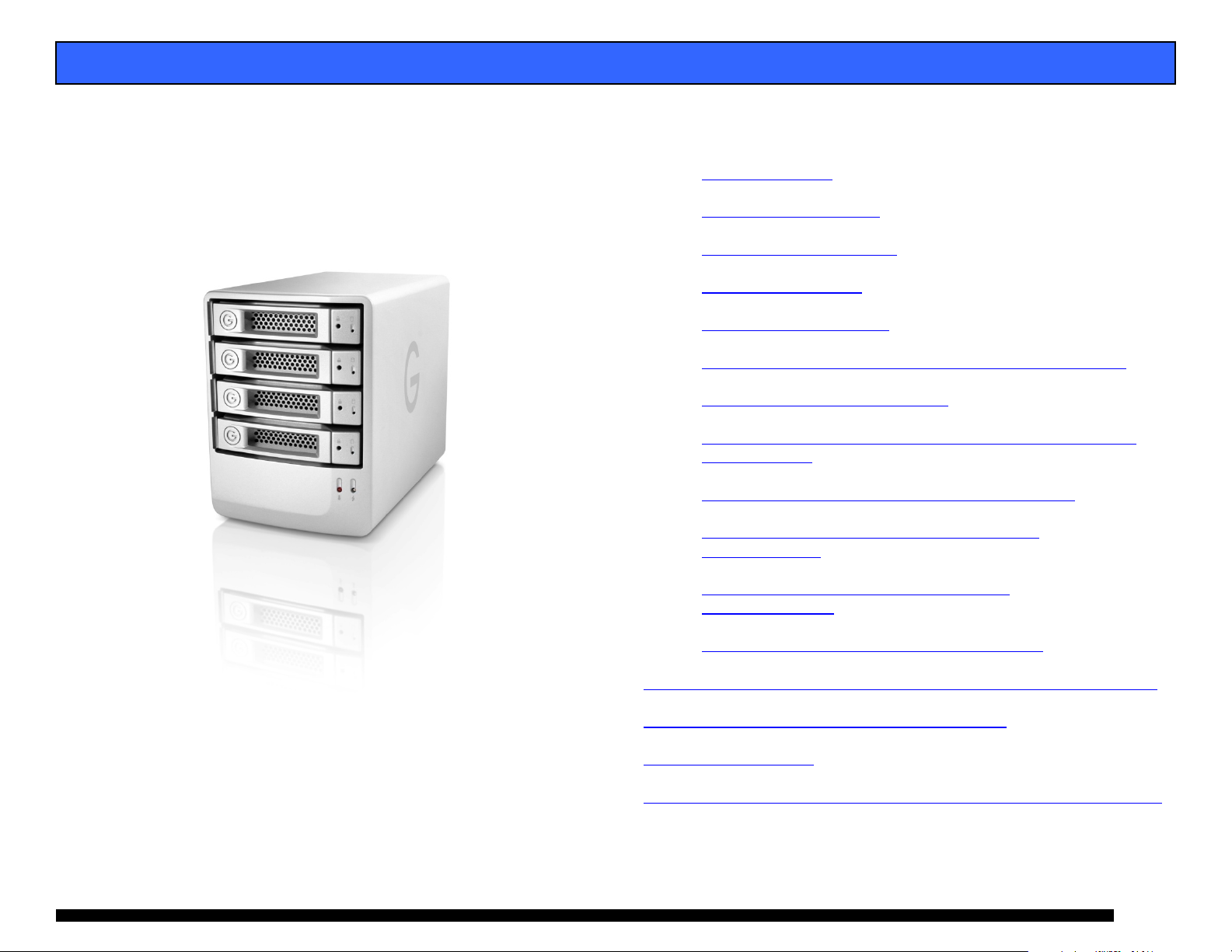
G-SPEED™ eS
Windows
Installation Guide
G-Technology Inc.
Tel: (310) 449-4599
Fax: (310) 449-4670
support@g-technology.com
P/N GSPEED eS v1.1PC
TABLE OF CONTENTS
1. INTRODUCTION (Pg 4)
2. SAFETY PRECAUTIONS
3. SYSTEM REQUIREMENTS
4. WHAT’S IN THE BOX
5. G-SPEED eS OVERVIEW
6. OPTIONAL G- TECH PCIe RAID CONTOLLER OVERVIEW
7. G-SPEED eS AUDIBLE ALARMS
8. SETTING UP G-SPEED eS WITH THE G-TECH PCIe RAID
CONTROLLER
9. SETTING UP G-SPEED eS USING THE WEB GUI
10. CONFIGURING TWO G-SPEED eS UNITS IN
RAID 5 MODE
11. WHAT TO DO IN THE EVENT OF A DISK
DRIVE FAILURE
12. TECHNICAL SUPPORT/LIMITED WARRANTY
APPENDIX A – DETAILED INFORMATION ON USING THE WEB GUI
APPENDIX B – EXPLANATION OF RAID LEVELS
APPENDIX C – NOTES
APPENDIX D – FORMATTING G-SPEED USING DISK MANAGEMENT
(Pg 6)
(Pg 16)
(Pg 5)
(Pg 6)
(Pg 12)
(Pg 19)
(Pg 20)
Page 1
Page 2
G-SPEED eS INSTALLATION GUIDE - Windows
Page 2
Page 3
G-SPEED eS INSTALLATION GUIDE - Windows
Page 3
Page 4
G-SPEED eS INSTALLATION GUIDE - Windows
1. INTRODUCTION
Thank you for purchasing G-SPEED eS from G-Technology,
Inc. (G-Tech)! Specifically designed for professional content
creation applications, G-SPEED eS features a high-speed
3Gbit/sec eSATA interface and when used in conjunction with
the optional G-Tech PCI Express (PCIe) RAID controller
provides RAID 0, 1, 5, 10 and JBOD functionality with
greater than 2TB support in Windows 32bit environments.
Up to four G-SPEED eS units can be attached to the G-Tech
RAID controller for storage capacities to 16 TB and data rates
over 600 MB/sec. G-SPEED eS supports multi-stream video
editing workflows.
2. SAFETY PRECAUTIONS
The disk drives contained in your G-SPEED eS are delicate
electronic instruments and are susceptible to damage due to
excessive physical shock. Place the unit in a vented area away
from moisture or liquids. Please handle the unit with care. Do
not open the case. Doing so will void the warranty. If the
Product is returned with damage caused by improper
handling, the warranty will be void and liability will rest with
the user.
3. SYSTEM REQUIREMENTS
• PCIe equipped workstation
• Microsoft Windows 2000/XP/2003/Vista
• G-Tech PCIe RAID Controller or third party port multiplier
aware eSATA host adapter
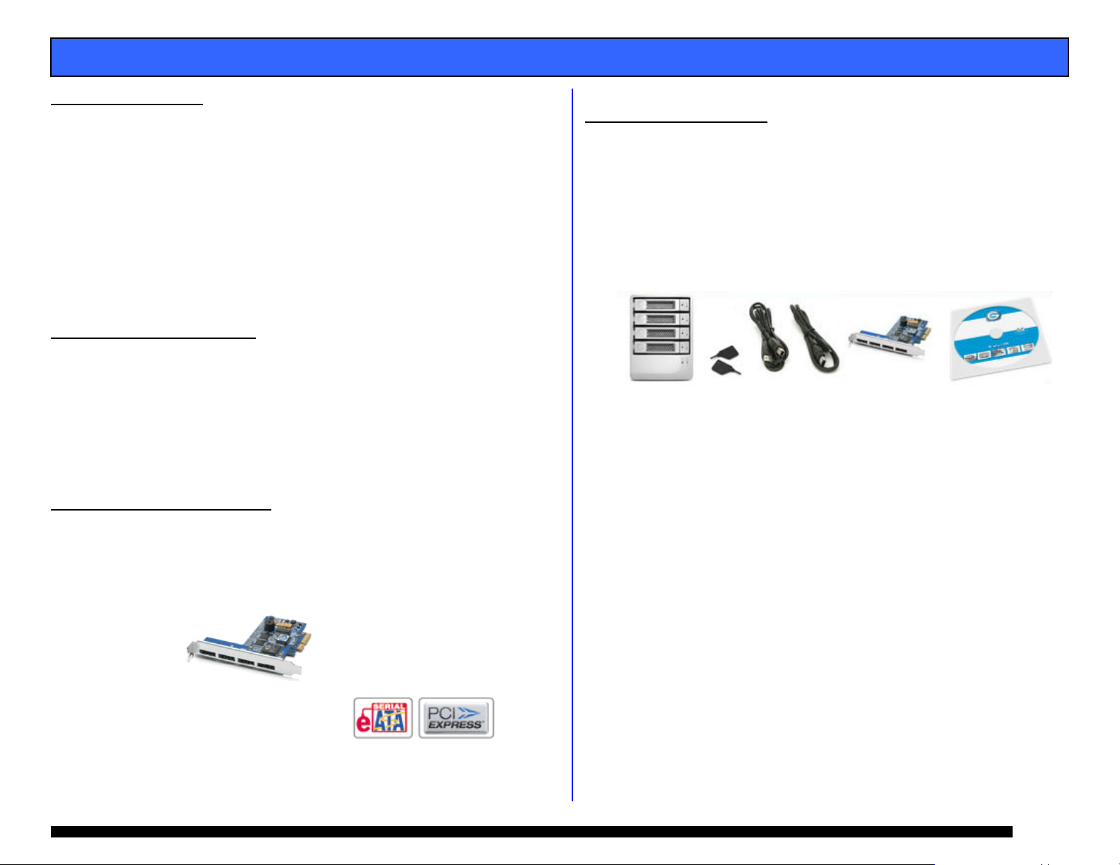
Optional G-Tech 4-port,
PCIe x4 RAID Controller
4. WHAT’S IN THE BOX
Take a moment to ensure that the following items are
included in the box. If anything is missing, please call G-Tech
at (310) 449-4599. Please keep the shipping container and
packing materials. In the unlikely event that you need to
return G-SPEED eS to us for any reason, you must use the
G-Tech shipping container. If the Product is returned
damaged caused by improper packaging, the warranty will be
void and liability will rest with the user.
• G-SPEED eS storage system
• 4 removable SATA drive modules (installed in unit)
• (2) disk module keys
• 1-meter eSATA cable
• AC Power cable
• Optional – G-Tech PCIe RAID controller
• Configuration Utility & Installation CD
Page 4
Page 5
G-SPEED eS INSTALLATION GUIDE - Windows
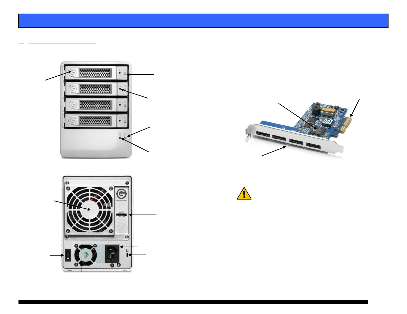
G-SPEED eS OVERVIEW
5.
(4) Removable
Disk Drive Modules
Remo
vable
Fan
ON/ OFF
Switch
6. OPTIONAL G-TECH PCIe RAID CONTOLLER OVERVIEW
The optional G-Tech PCIe RAID controller connects
G-SPEED eS to your PCIe equipped workstation and
provides RAID 0, 1, 5, 10 & JBOD functionality. You w ill
Drive Module
Power/Activity
LED
choose your level of RAID protection when you set up
the G-SPEED eS in Section 8. For an explanation of
supported RAID levels, please refer to Appendix B.
Disk Module
Lock Hole
Power Supply
LED
Temperature/Fan RPM
Warning LED
(4) High-speed
3 Gb/s eSATA ports.
Supports up to (4)
G-SPEED eS systems
RAID Engine
PCIe x4 interface
3 GB/sec
eSATA
Port
AC Input
Cable Lock
Hole
G-SPEED eS is also compatible with third-party Windows
port multiplier aware eSATA host adapters. Refer to your
host adapter documentation to set up G-SPEED eS with
these boards.
Page 5
Page 6
G-SPEED eS INSTALLATION GUIDE - Windows
7. G-SPEED eS AUDIBLE ALARMS
7.1 The G-SPEED eS enclosure is equipped with an audible
alarm that sounds when:
1. The internal temperature of the G-SPEED eS enclosure
reaches a temperature of 60° centigrade
and/or
2. When the main FAN fails or the RPM of the fan slows to
a state where the fan can longer adequately cool the
system.
In addition to the audible alarm, the Temperature/Fan
Warning LED located on the front bezel of G-SPEED eS
will illuminate.
If you hear an audible alarm and see the RED warning LED on
the front of G-SPEED eS, stop using G-SPEED eS immediate ly.
Check to see if the fan is spinning and move the unit to a
cooler location. If the problem persists, contact G-Tech
Support.
7.2 The G-Tech RAID controller is also equipped with an
audible alarm that sounds when:
1. A disk drive failure occurs
or
2. When the G-SPEED eS is removed from the RAID
controller without first selecting “Unplug” in the Array
Maintenance menu in the web GUI.
If you hear an audible alarm coming from the G-Tech RAID
controller, see Section 11 “What to do in the Event of a Disk
Drive Failure”. See Appendix B.1.7.2 for information on the
proper way to hot “Unplug” G-SPEED eS.
8. SETTING UP G-SPEED eS WITH THE G-TECH PCIe
RAID CONTROLLER
Connecting G-SPEED to your workstation and configuring
your system takes just a few steps as outlined below. For
this example we will be installing G-SPEED eS on a
Windows XP system. The installation is similar for
Windows 2000, 2003 and Vista.
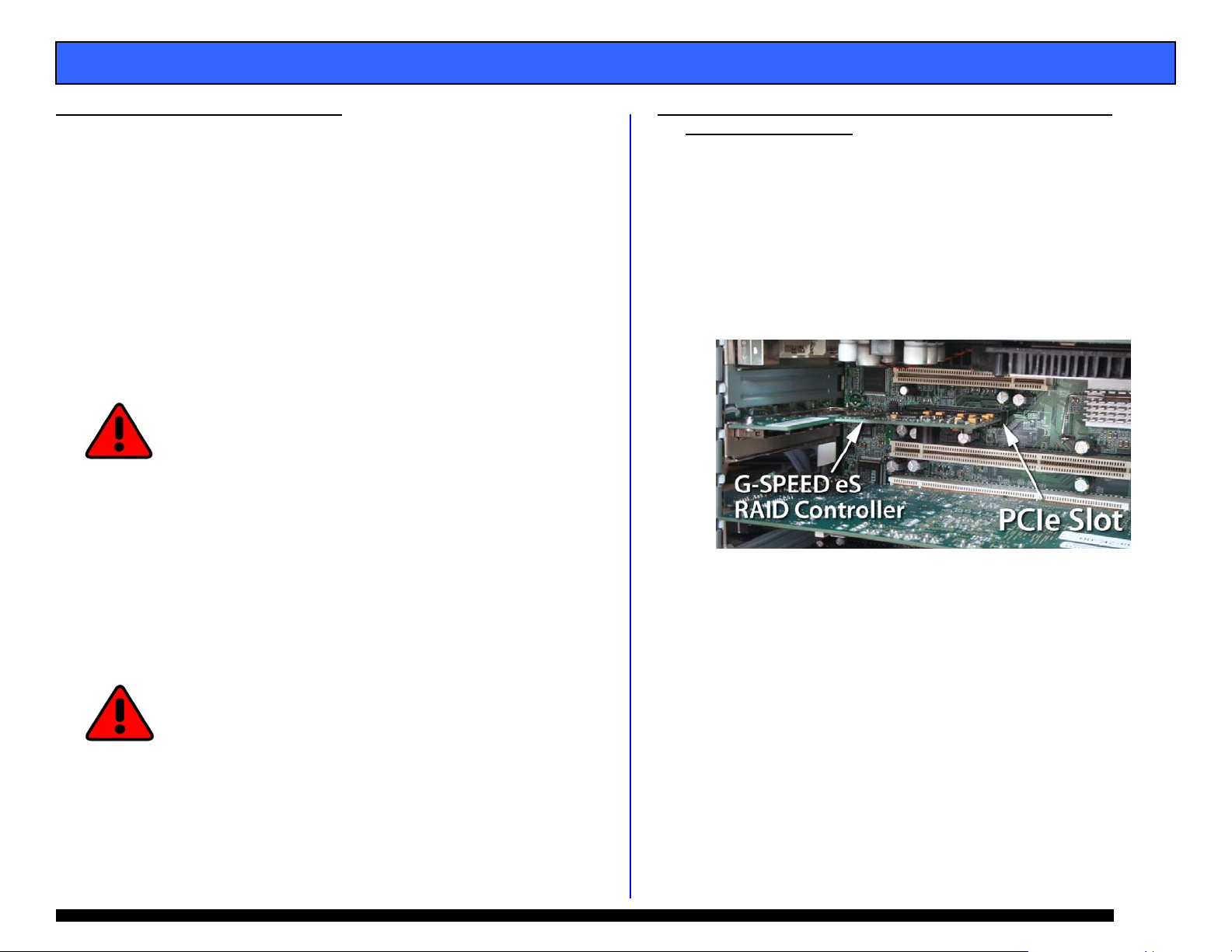
8.1 Installing the G-Tech PCIe RAID Controller
1. Install the G-Tech RAID controller into an available PCIe
slot in your workstation.
2. Secure the RAID controller in place.
Page 6
Page 7
G-SPEED eS INSTALLATION GUIDE - Windows
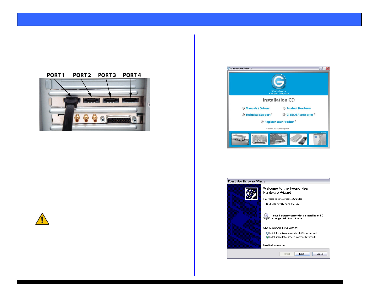
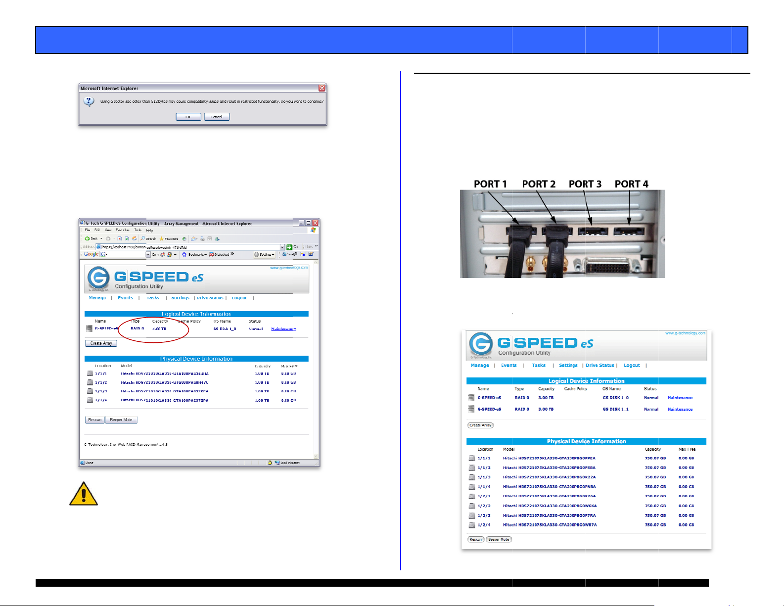
8.2 Attaching G-SPEED eS to the G-TECH RAID Controller
1. Attach one end of the supplied eSATA cable to the eSATA
port located on the back of G-SPEED eS.
2. Attach the other end of the eSATA cable to Port 1 (port
closest to motherboard) on the G-Tech RAID controller as
shown below.
3. Attach the power cord to the back of G-SPEED eS and
connect the other end to AC power.
4. Power on G-SPEED eS.
8.3 Installing the G-Tech PCIe RAID Controller Software
There are three steps required to fully install the software
for the G-SPEED eS Controller.
1. Install the Windows driver
2. Update the Controller firmware
3. Installing the web GUI
Check for software updates at
http://www.g-technology.com/Support/
1. Install the G-SPEED eS Windows driver
a. Power on the workstation
b. Insert the G-Tech Product CD into the CD-ROM drive
When the CD loads a welcome screen may appear.
Close this window.
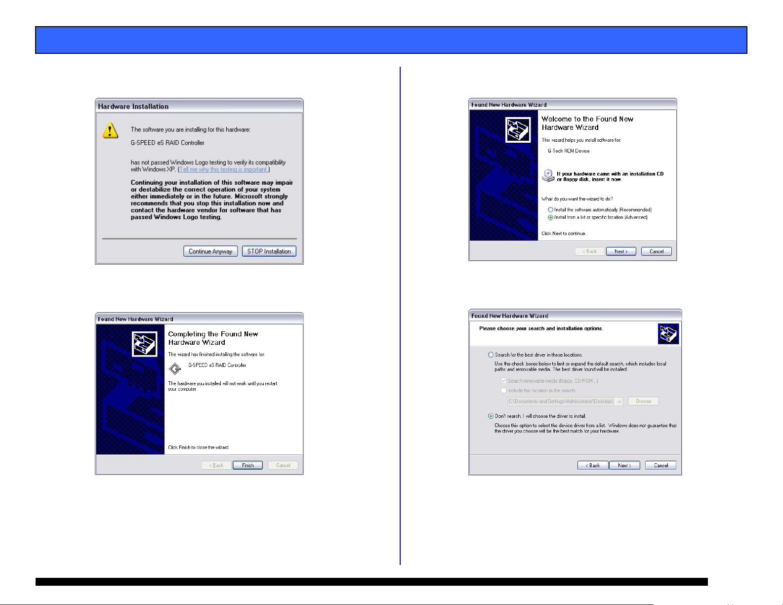
c. When the system boots the “Found New Hardware
Wizard” will appear. Select “Install from a list or specific
location” and click <Next>.
Page 7
Page 8
G-SPEED eS INSTALLATION GUIDE - Windows
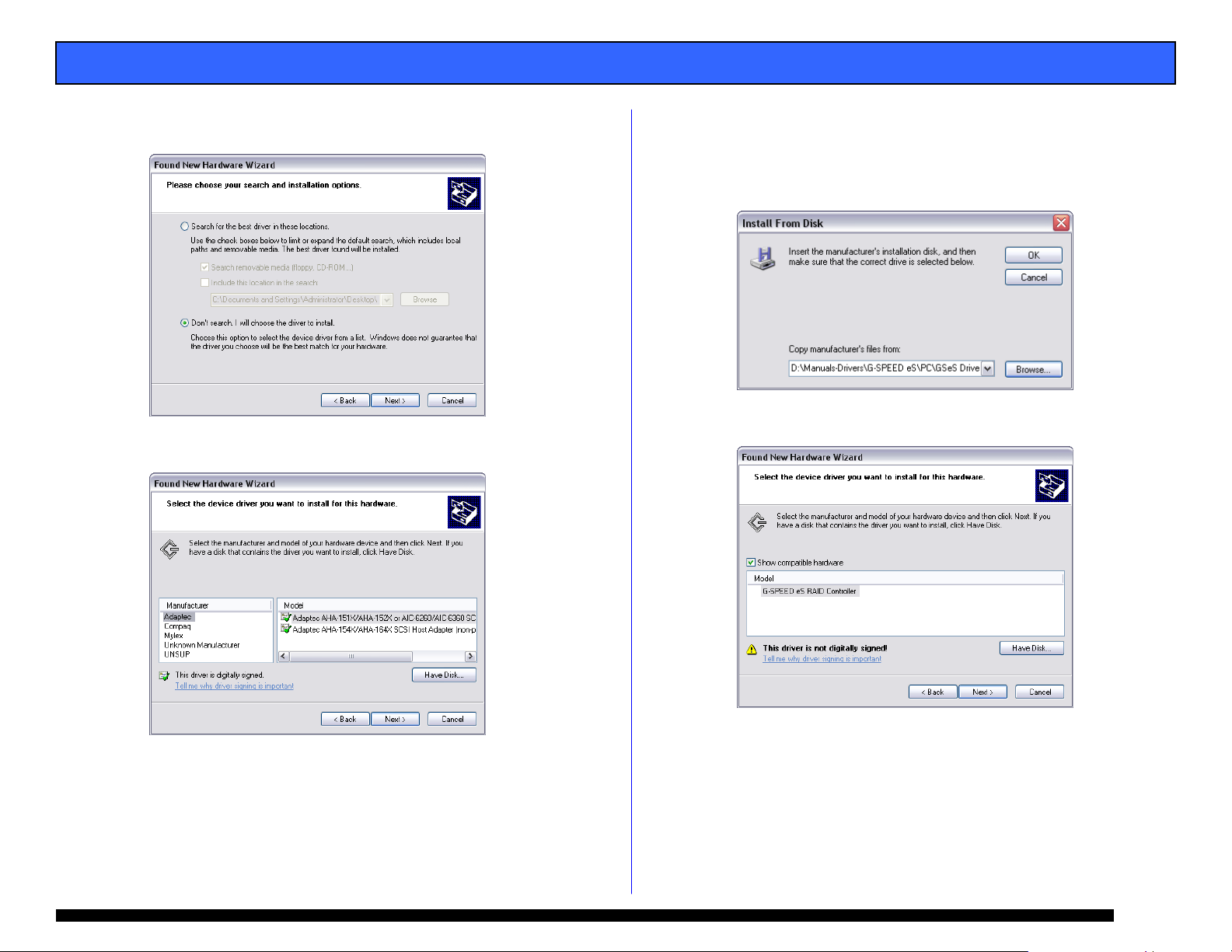
d. Select “Don’t Search, I will choose the driver
to install” and click <Next>.
e. Click <Have Disk>.
f. Click on the <Browse> Button and navigate to the CD-
ROM drive containing the G-Tech Product CD. Continue
to “\Manuals-Drivers\G-SPEED eS\PC\GSeS Driver Winv1.0\” Select the folder for your operating system and
click <OK>.
g. Select “G-SPEED eS RAID Controller and click <Next>.
Page 8
Page 9
G-SPEED eS INSTALLATION GUIDE - Windows
h. When the Windows Logo warning screen appears
click <Continue Anyway>.
i. The RAID controller driver will install and the Wizard
will complete. Click <Finish>.
j. A new “Found New hardware Wizard” will open for the
“G-Tech RCM device.” Click <Next>.
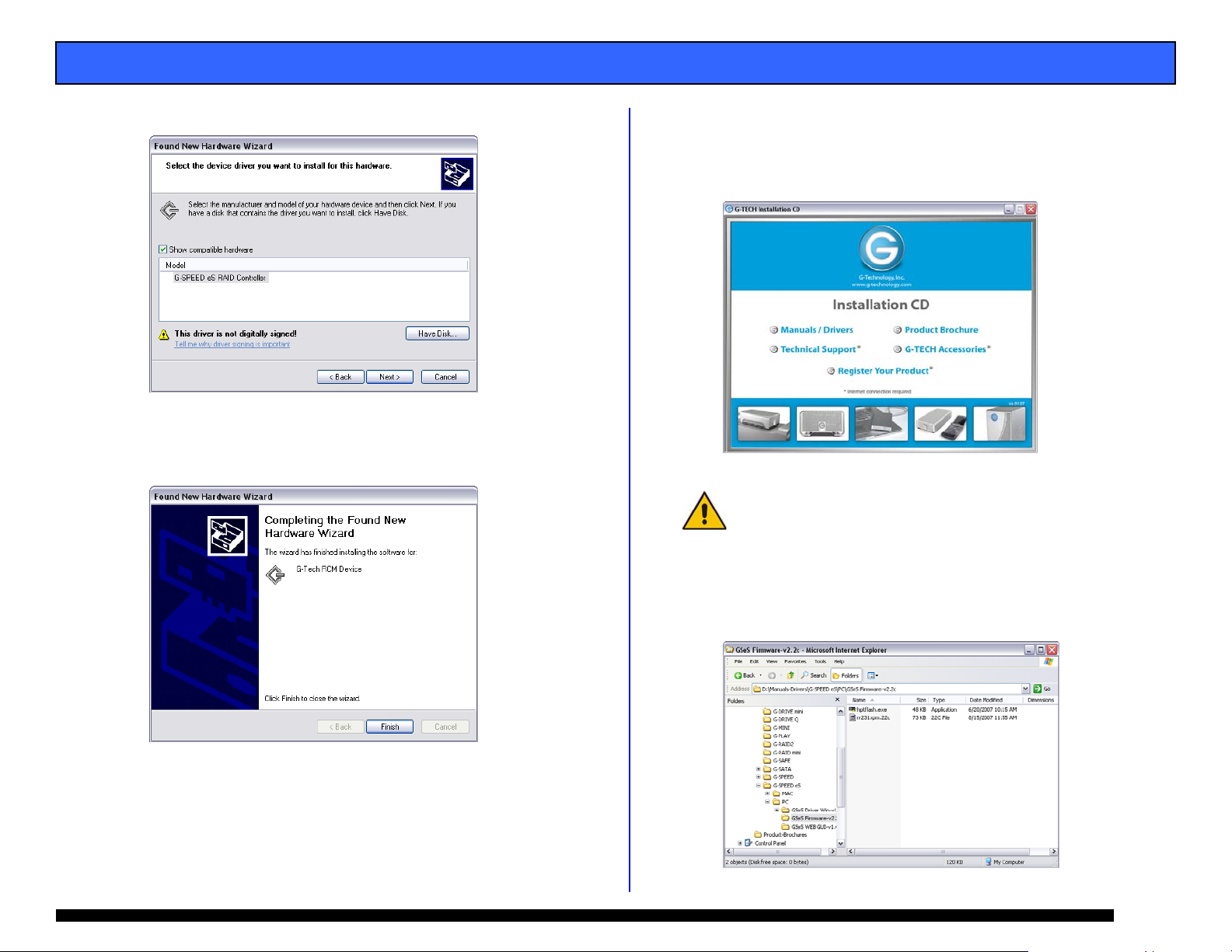
k. As before, click on “Don’t search. I will choose the
driver to install.”
Page 9
Page 10
G-SPEED eS INSTALLATION GUIDE - Windows
l. Select “G-SPEED es RAID Controller” and click <Next> .
m. The RCM Device driver will install and the Wizard will
complete. Click <Finish>. This completes the driver
installation.
2. Update the G-SPEED eS Controller firmware
a. Insert the G-Tech Product CD into the CD-ROM / DVD
drive. When the disk loads a welcome screen should
appear. Click on the <Manuals / Drivers> link.
NOTE: If the Menu screen does not appear, the “autorun” feature
may not be enabled on your workstation. To load the menu
manually go to the START menu and click on “Run.” Enter the drive
letter of your CD-ROM containing the Product CD and then
“autorun.exe.” For example “D:\autorun.exe”
b. This will open Windows Explorer. Navigate to the
“G-SPEED eS\PC\GSeS Firmware-v2.2c” folder.
Double-click “hptflash.exe” to launch the flash utility.
n. Remove the G-Tech Product CD.
o. Restart your workstation.
Page 10
Page 11

G-SPEED eS INSTALLATION GUIDE - Windows
c. Click <Open...>.
d. Select “rr231.xpm.22c” and click <Open>.
f. When the process is completed click <OK>.
g. Remove the G-Tech Product CD.
h. Restart your workstation.
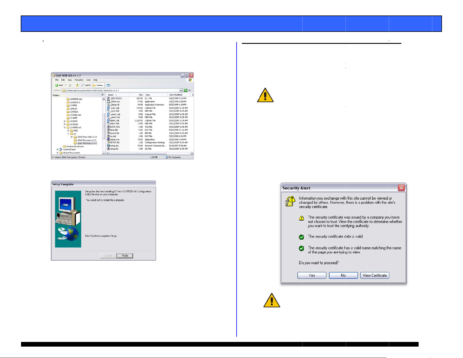
3. Installing the G-SPEED eS Web GUI.
a. Insert the G-Tech Product CD. When the disk loads a
welcome screen should appear. Click on the <Manuals /
Drivers> link.
e. Click <Flash!> to begin the update process.
Page 11
Page 12
E
b
A
t
s
E
”
m
e
o
W
e
T
TmaeG
wsd
1
2
S
I
w
T
n
m
.
h
B
h
w
/
n
t
N
w
t
s
w
o
P
c
S
o
n
4
e
o
y
G
d
r
o
r
o
S
b
l
W
ge
a
s
t
r
e
g
U
s
G-SP
ED eS INST
LLATION G
UIDE - Wind
ws
. Navigate to
“Manuals-Dr
Double click
instructions,
c
. When the in
he folder:
ivers\G-SPEED
on “Setup.exe
accepting the
tallation is co
eS\PC\GSeS
and follow th
defaults.
plete click <F
EB GUI-vX.X”
onscreen
inish>.
9. SE
TING UP G-
he G-Tech RA
ny web bro
quivalent.
-SPEED eS o
ith a new technol
ize presented to t
isks of up to 16T
9.
1 Accessing t
. Open your
. The followi
onitor the G-
NOTE: W
built-in li
(2048GB)
https:
<YES> but
PEED eS USI
D controller
SPEED eS sys
ser such a
his section
a Windows w
indows 2000 / X
itation that logi
The G-SPEED e
ogy, Variable Sect
e operating syste
.
e G-Tech PC
eb browser a
/localhost:7
g Security Al
on.
G THE WEB
eb GUI is use
em. The GUI
Safari, Inte
ill describe h
rkstation.
are 32 bit ope
al disks cannot
RAID Controller
or Size (VSS). V
m making it possi
Ie RAID Cont
d enter the fo
02
rt window will
UI
to configure
is accessed u
net Explorer
w to setup
ating systems wi
be greater than
vercomes this ba
S increases the s
le to now have lo
roller Web G
lowing addres
appear. Click
nd
ing
or
the
h a
2TB
rier
ctor
ical
I
:
the
d
. The Web GU
your G-SPE
I is ready to b
D eS.
launched and
configure
NOTE:
save th
For easy access t
e web address in
the G-SPEED eS
our favorites
eb GUI
Pa
12
Page 13
E
A
n
o
e
N
n
o
0
s
s
T
r
o
T
e
a
s
e
v
a
s
T
n
P
a
o
T
s
l
ge
n
n
a
e
w
G-SP
ED eS INST
3.
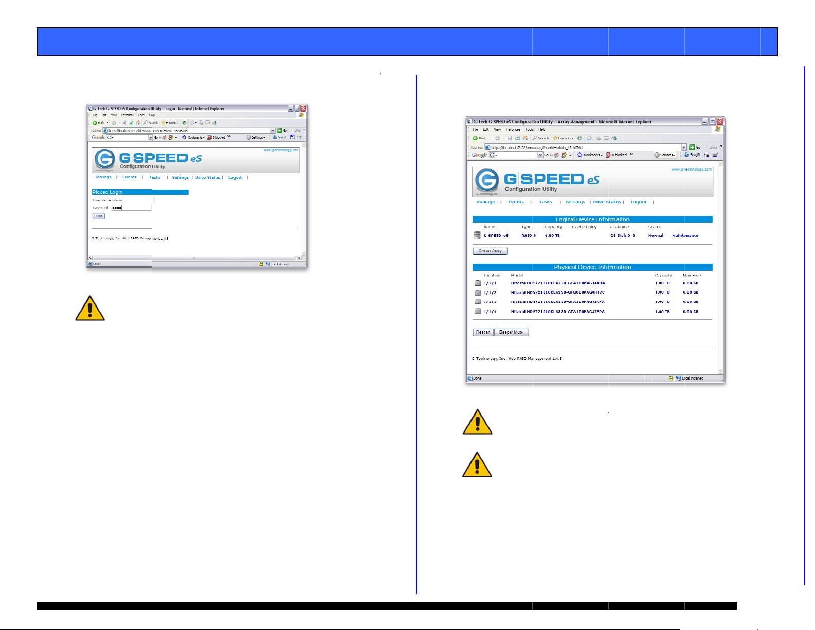
Enter “admi
as the Passw
Note: S
changing
LLATION G
” as the User
rd and click o
e appendix A.4.
the password.
UIDE - Wind
ame and “00
the <Login>
5 for instruction
ws
0” (four zero
button.
on
) 4.
he main sc
below. Each
the “Physical
een of the w
f the four dri
Device Inform
b GUI will ap
es in the unit
tion” section
pear as show
re displayed i
f the GUI.
Note:
formatt
and r
workst
he G-SPEED eS i
ed for Mac OSX.
-created to fu
tion. Section 9.2
shipped initialize
his configuration
ction correctly
covers this proces
d as a RAID 0 arr
needs to be delet
on your Windo
.
y
d
s
NOTE:
feature
Please refer to AP
of the G-Tech RA
ENDIX A for detai
ID Controller web
ed information on
GUI.
Pa
the
13
Page 14

E
C
ofo
A
h
S
A
o
t
T
M
W
e
i
<
o
e
b
e
I
n
e
e
3
4
O
Wsto
e
p
e
o
e
ge
G-SP
9.2
ED eS INST
onfiguring t
T
he G-SPEED e
nfigured in R
c
r an explanati
b
elow to setup
1.
Launch the G-
2.
Click on the “
below will app
Maintenance
LLATION G
e RAID level
/G-Tech RAID
ID 0, 1, 5, 10
n of RAID lev
he system
ech RAID Con
aintenance” L
ear. Click on
indow.
UIDE - Wind
of G-SPEED
controller com
and JBOD. (S
ls) Follow the
troller web GU
nk and the wi
Delete> in th
ws
S
ination can b
e Appendix B
directions
.
dow shown
Array
. Click the <
K> button to
roceed.
ARNING: This wil
red on G-SPEED
l delete any data
S!
. The GUI wi
the <Creat
ll refresh and
Array> butto
the array is n
n. The “Creat
w deleted. C
Array” page
lick
will
appear.
Pa
14
Page 15

E
A
t
a
h
a
e
n
a
w
p
n
T
R
n
s
o
n
p
A
d
T
G
O
y
u
”
o
.7.
.
o(s
e
e
v
t
e
rUp 2TB4TB8TB
u
n
e
y
w
P
e
t
s
v
S
m
a
a
r
A
b
u
ge
h
G-SP
ED eS INST
LLATION G
UIDE - Wind
ws
5.
The Create A
array and all i
a RAID 0 arr
select it from
Select RAID
“Array Name”
rray page is
s parameters.
y. (To s et u
the dropdow
0 for “Array
here you co
In this exam
a different R
menu labele
ype”, enter
figure the ne
le we will set
ID level simp
“Array Type.
-SPEEDeS f
w
p
ly
)
r
6
Click the <S
lect All> to q
ickly select all
the disks for t
e
array.
To create an
enter the val
array less tha
ue in MB in th
the maximu
Capacity field
available,
.
8
If you are cr
choose the
indicated in
ating an arra
alue for Variab
he table belo
of Greater th
le Sector Size
.
n 2TB,
s
vercomes this ba
VSS). VSS incr
ystem making it p
NOTE: In t
system can
selecting th
NOTE: Whe
the initializ
approximate
is example we are
lso be set up in
appropriate setti
creating redunda
tion process take
ly 1hr 45m per TB
creating a RAID 0
AID 1, 5, 10 or JB
g in the “Array T
nt arrays (RAID 1
time. For RAID 5
of final capacity.
array. The
D mode by
pe” pull-down.
or RAID 5)
it takes
Ar
NOTE: W
with a bui
than 2TB
ay Capacity
to 2TB
-> 4TB
-> 8TB
-> 16TB
indows 2000 / X
lt-in limitation tha
(2048GB). Th
rrier with a new
ases the sector
ossible to now ha
ector Size
512
1k
2k
4k
are 32 bit ope
t logical disks can
G-SPEED eS R
echnology, Varia
ize presented to
e logical disks of
ating systems
not be greater
ID Controller
le Sector Size
the operating
p to 16TB.
Pa
15
Page 16
E
.11.
.
A
n
r
p
e
r
h
a
D
p
r
S
m
p
n
I
n
e
T
a
m
s
W
o
a
g
S
y
m
p
t
a
>
CFa
G
e
n
h
a
u
e
a
y
E
t
A
n
u
w
k
I
e
T
n
c
b
ge
O
G
G-SP
ED eS INST
9.
Click <OK> o
10
Click the <C
initialize. A
been creat
The GUI will
completed init
LLATION G
the warning
eate> button
opup will ap
d and is no
eload indicati
ializing the RA
UIDE - Wind
essage that a
and the arr
ear confirmin
w initializing.
g that the G-
D 0 array.
ws
ppears.
y will begin
the array h
Click <OK
PEED eS has
o
s
10.
ONFIGURIN
ollow the dir
rrays in RAID
1. Ensure tha
installed a
2. Attach bot
controller
.
your comp
TWO G-SPE
ctions below
5 mode using
t the G-Tech R
d the driver a
G-SPEED eS
s shown belo
ter
D eS UNITS
to configure
he G-Tech RAI
ID controller i
d web GUI ar
nits to the G-
, power the u
N RAID 5 M
two G-SPEED
D controller.
s properly
loaded.
ech RAID
its and restart
DE
eS
12
Yo u r G- SP EE
with your o
detailed inst
format the G-
NOTE: W
the initiali
approxim
en creating redu
zation process tak
tely 1hr 45m per
eS is now re
erating syste
uctions on u
PEED eS for
dant arrays (RAID
s time. For RAID
B of final capacit
dy to be for
. See Ap
ing Disk Ma
indows XP.
1 or RAID 5)
5 it takes
.
atted for use
endix D for
nagement to
3. Launch th
two units
will displa
G-Tech RAID
ttached to the
information li
Controller we
G-Tech RAID
e that shown
b GUI. With
ontroller, the
elow.
the
UI
Pa
16
Page 17

E
CN
Cw
C
R“D
A
k
e
N
>
r
h
e
e
G
o
a
h
G
<
e
t
n
e
t
o
C
ge
G-SP
ED eS INST
4.
lick on the “M
ame” GS Dis
LLATION G
aintenance” lin
1_0. The win
UIDE - Wind
k next to the
dow shown bel
ws
rray with “OS
ow will appear.
Click the <
8.
appear.
Delete> butto
and the foll
wing window
will
5.
lick the <Del
ill appear.
6.
lick the <OK
7.
epeat the p
Maintenance”
isk 1_1. The
te> button. T
WAR
ING: This will del
stored
on G-SPEED eS.
button to del
ocedure for
link next to t
window below
e following wi
te any data
te the array.
S Disk 1_1.
he array with
will appear.
ndow
Click on t
“OS Name”
e
S
9.
C
lick the
arrays hav
the <Crea
window will
WARNING: This
stored on G-SPEE
OK> button
now been d
e Array> bu
appear.
will delete any dat
D eS.
to delete the
leted as show
ton. The “
a
array. Both
n below. Click
reate Array”
Pa
17
Page 18

A
w
E
a
t
“
t
h
o
a
s
”
112
3
4
5
T
c
S
m
z
p
G
m
s
X
K
a
e
f
n
n
ge
t
A
u
i
G-SPEED eS INST
LLATION G
UIDE - Wind
ws
10.
In this windo
Select RAID
Enter G-SPE
Select Foreg
and Write B
Click <Select
<Create> bu
select the fol
5 for “Arr a y Ty
D-eS-R5 for
round for “Ini
ck for “Cache
All> button to
ton to begin t
lowing values
pe:”,
Array Name:”,
ialization Meth
Policy:”
select all disk
e initialization
s shown:
od:
then click the
process.
1
. A popup wil
created and
. The GUI wil
initializing.
l appear confir
is now initiali
l reload indicat
ing the array
ing. Click <O
ing that the G-
has been
>.
SPEED eS is
. The RAID
1
45m per
process is
5 and “Stat
. Your G-SPE
1
with your o
instructions
G-SPEED e
initialization
B of final ca
omplete, the
us” as Normal
ED eS is now
perating syste
on using Di
for Windows
rocess takes
pacity. Once
UI will indicat
.
ready to be
. See Appe
k Manageme
P.
pproximately
the initializa
“Type” as R
ormatted for
dix D for deta
t to format
Pa
1hr
ion
ID
se
led
the
18
Page 19

E
HTheafai
o 123
A
d
G
5
a
a
S
e
e
O
t
E
u
h
o
f
o
g
t
e
t
o
I
n
t
e
t
e
a
e
n
r
f
k
w
e
e
c
f
y
d
N
e
w
e
O
S
n
o
p
m
G
I
N
A
e
h
n
t
o
-
h
R
ge
o
e
r
t
E
G-SP
ED eS INST
LLATION G
UIDE - Wind
ws
11. W
AT TO DO IN
e G-Tech RAID
ch of the disk
lpure, an audibl
re
ort the failed
NOTE: If
(RAID 1,
However, t
drive shoul
llow the steps
F
. Launch the
. Mute the al
button.
. The GUI wi
An exclam
that the “
portion of
G-SPEED
THE EVENT
controller con
rives in G-SP
e alarm will so
drive and its p
-SPEED eS was c
or 10), a drive
he array is now in
d be replaced as s
below to identi
web GUI.
rm by clickin
ll display infor
tion mark on
tatus” of the
the GUI ind
S unit has fail
F A DISK DR
inually monito
ED eS. In the
nd. The web
ysical positio
nfigured in a pro
ailure does not r
an unprotected s
on as possible to
fy and replace
on the <Beep
mation like th
he G-SPEED
array is Crit
icates which
d.
VE FAILURE
rs the health o
event of a dis
GUI will also
.
ected RAID mode
sult in data loss.
ate and the failed
avoid data loss.
a failed drive.
r Mute>
t shown belo
S icon indicat
ical. The low
drive in whi
s
r
h
4.
Remove the
G-SPEED eS
controller) b
and gently sli
ailed drive (I
connected t
inserting the
ing the drive
this exampl
port 2 of t
rovided key i
odule out of
Drive 3, of t
e G-Tech RA
to the lock h
he enclosure.
he
ID
le
.
X
WAR
ING: Make abso
indicated by the
drive
conn
cted to the G-Tec
follo
the cable to ensu
conn
cted to on the RA
REM
VING THE WRO
LOS
OF THE ARRAY
ON G
-SPEED eS.
In this e
to the G
connect
xample there are
Tech RAID contro
d to Port 2 of the
wo G-SPEED eS u
ller. Drive 3 of the
G-Tech RAID cont
its connected
G-SPEED eS
oller has failed.
lutely sure that y
UI. If multiple G
h RAID controller,
re you know whic
D controller.
G DRIVE WILL
ND ALL OF THE
u remove the fail
SPEED eS units a
it is a good idea
Port # the array
ESULT IN THE
CONTENT STOR
Pa
d
e
o
is
D
19
Page 20

E
R
RT
ON
C
fplfo Wofav
A
t
l
r
e
e
0
g
e
g
o
o
v
e
a
v
t
4
h
-
p
v
o
n
o
o
e
a
e
s
v
m
o
o
t
r
w
w
D
h
n
IGausGRortPasMtGboewGFaG( ITRPDDITHTI
R
e
e
i
n
f
a
u
i
e
p
m
e
3
9
T
L
O
C
G
O
U
T
G
T
w
w
r
w
r
o
a
w
y
c
e
a
a
e
d
g
w
e
g
E
I
N
H
A
T
T
O
T
r
c
l
s
n
s
a
T
d
e
r
t
o
C
R
A
S
I
S
D
O
ge
G-SP
5.
6.
12. TE
ED eS INST
eplace the fai
i
n place. Once
i
ndicate that
ebuilding an
he rebuild tim
nce the rebui
ormal and p
HNICAL SUP
I
y u encounto
ease contact
llowing ways:
phonTele
Fax: (31
E-mail: s
Internet:
hen contactin
your comput
ailable:
• r G-S
You
• atin
Oper
• Compute
• eSATA h
• Amount
• Other de
LLATION G
led drive with
the drive has
he array is r
d the percent
e is approxima
d is complete,
otecting your
PORT
r any difficul
G-Tech Techn
: (310) 449-
) 449-4670
upport@g-tec
http://www.g
Technical Su
r and have th
PEED eS serial
system and
r brand and m
st adapter bra
f memory inst
ices attached
UIDE - Wind
a new disk m
spun up to sp
building (The
ge complete)
tely 2 hours p
G-SPEED eS i
aluable data o
ies while inst
ical Support
599
nology.com
technology.co
port, make su
e following inf
number (on b
ersion
del
d and model
alled
to your compu
ws
dule and secu
ed, the GUI w
“Status” sho
s shown belo
r TB.
back to
nce again.
alling G-SPEE
ia one of t
/support
re to be in fro
rmation readi
ttom of unit)
er
e
ill
s
e
ly
.
,
t
13. L
MITED WAR
-Technology I
ny defect in
se, for the d
hould becom
-Tech, will at
epair or repla
n an excha
econditioned.
he Property o
roduct has be
s a result of
ervice is avail
aterial Autho
he Product d
-Tech service
ear all shipp
ther costs,
ffe te rectua
arranty. All
-Tech in the o
or more infor
n RMA numb
-Tech at 165
310) 449-459
N THE EVENT
HE WARRAN
EMEDY SHA
ROVIDED AB
AMAGES, IN
ATA, ARISIN
MPLIED WARR
ECH AND, T
EREBY EXCL
O THE EXTEN
NJURY DAMA
ANTY
nc. (G-
material and
signated war
defective
ts discretion,
cement parts
ge basis an
All replaced p
G-Tech. This
en damaged b
unauthorized
ble to the pur
rization numb
ring the warr
facility or to
ng, packing
xcluding part
air, replacem
returned Pro
riginal shippin
ation on ho
r or to acquir
Stanford Stre
or support@
A PRODUCT B
Y PERIOD, TH
L BE REPA
VE. INCIDE
LUDING WIT
FROM BRE
ANTY ARE NO
THE EXTEN
DED BOTH F
NOT UNCON
E.
ech)
arrants your P
orkmanship,
anty period.
ithin the wa
epair or repla
r Products wi
d will be ei
rts or Product
arranty shall
accident, mi
service or p
haser by obta
r (RMA) and
nty period to
ech. The p
G-
nd insurance
s and labor,
nt or refun
uct must b
container.
to obtain wa
shipping ma
et, Santa Moni
-technology.c
COMES DEFE
E PURCHASE
R OR REPL
TAL OR CON
OUT LIMITAT
CH OF ANY
THE RESPON
PERMITTED
R PROPERTY
SCIONABLE, F
roduct against
under normal
If the Product
ranty period,
e the Product.
l be furnished
ther new or
shall become
ot apply if the
use, abuse or
rts. Warranty
ining a Return
by delivering
an authorized
urchaser shall
costs and all
necessary to
under this
shipped to
ranty service,
erials, contact
ca, CA 90404,
m.
TIVE DURING
’S EXCLUSIVE
CEMENT AS
EPROUENTAL
ON LOSS OF
EXPRESS OR
IBILITY OF G-
BY LAW, ARE
AMAGE, AND
R PERSONAL
Pa
20
Page 21
E
E
12345
6
A
B
s
G
a
H
t
o
b
s
e
n
.
t
a
e
m
m
e
P
f
d
e
a
m
t
t
e
x
i
o
n
e
d
n
t
”
a
e
c
n
o
R
s
t
A
A
y
P
D
x
m
n
D
a
a
l
i
v
a
r
n
e
g
f
e
m
a
r
a
n
ge
G-SP
APP
ED eS INST
NDIX A: WE
LLATION G
GUI
UIDE - Wind
ws
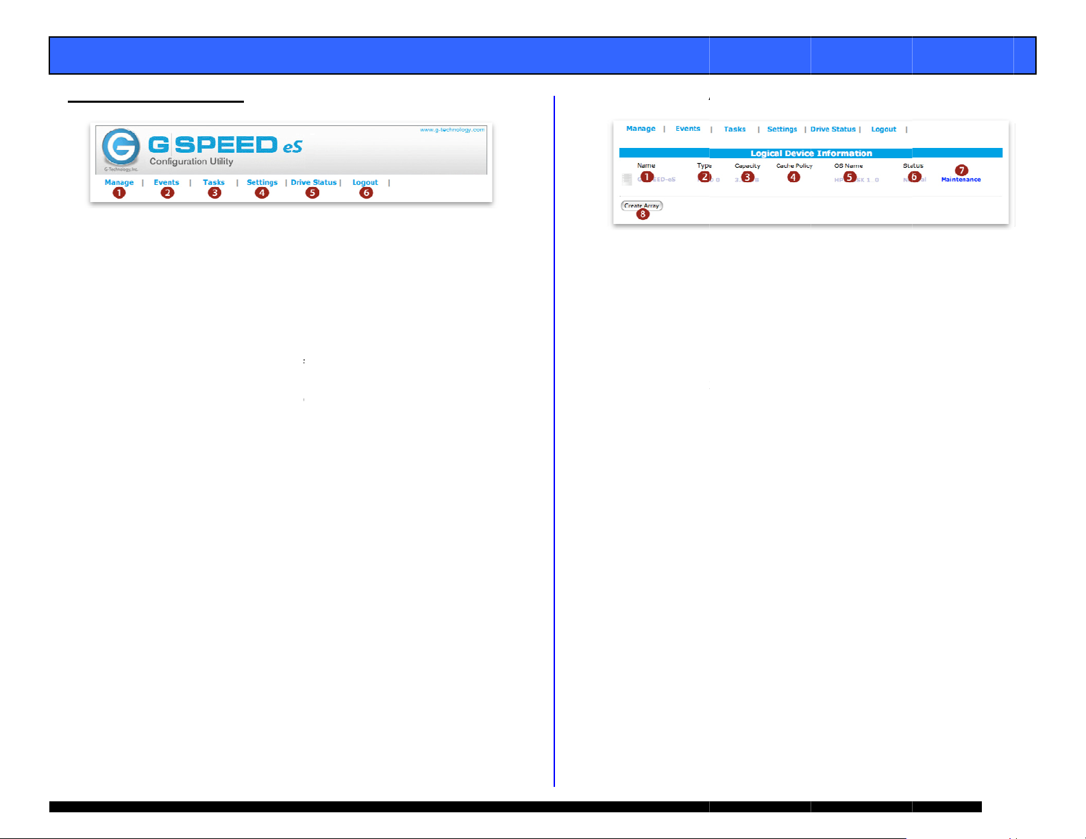
A.1 M age: an
rray
. Manage:
Array: Thi
web GUI.
from this p
Devices:
page (you
page as
performanc
Spare Po
drives can
called hot
added to th
. Events: All
recorded h
These eve
notification
. T
asks: Sch
au
tomatical
vo
lume.
. Settings:
settings s
notification
. Driv e Sta
h rd drivesa
. o L gout: S
is the main
-SPEED eS is
ge. (See App
ard drive para
should not
he drives ar
e with the G-S
l: When con
e assigned to
pare). These
e Array in the
events of the
re, such as
ts can be e
under the “Se
edule the G-Te
Configure th
uch as logi
See Appendi
us: Check th
including deta
y goodbye
screen of the
configured a
ndix A.1 for d
eters are mo
ake any cha
configured
EED eS.
igured in pro
a “spare pool
rives will be
vent of a driv
G-SPEED eS
rray changes
ailed by setti
tings” tab.
ch controller t
egrity of the
inly verify the
G-SPEED e
n password
A.4 for detail
e status of a
led SMART da
G-SPEED eS
d monitored
tails)
ified on this
ges on thi
for optims al
ected mode
(sometimes
utomatically
failure.
ontroller are
and failures.
g up email
AID
S controller
and email
ll connected
a.
1. Name:
2. Type: Di
3. Capacit
4. Cache
for RAI
appendi
5. OS Na
display i
6. Status:
Norm
Critic
Initia
Rebu
rray name (as
splays RAID le
: you guessed
olicy: Display
protected
B.1.7.7
e: Controlle
Disk Utility.
isplays curre
l: All systems
l: Drive failur
izing: Buildin
lding: Parity d
shown in GUI
el of array.
it… capacity o
s current writ
rrays. For
assigned n
t status of ar
go
has occurred
RAID 1, 5 or
ata being reco
only).
the array.
cache policy
ore info see
me that will
y.
10 array
structed
Pa
21
Page 22

E
A
e
u
l
D
N
A
B
m
e
h
t
L
s
o
a
t
S
a
o
f
e
A
e
p
e
T
A
h
h
L
o
e
A
e
n
c
e
C
.
b
e
t
t
m
r
o
r
d
a
s
e
_
C
r
g
t
s
o
y
m
t
s
t
v
D
T
p
t
t
ge
h
r
G-SP
ED eS INST
LLATION G
UIDE - Wind
ws
Maintenanc
7.
options for c
on RAID leve
RAID 0
7 1. Delete:
7.2 Unplug
controller.
option. This
system witho
7.3 Rename
rrent array. T
of the array.
WAR
THE
RRAY AND A
: This will di
e sure to cl
enables the ar
ut causing an
NOTE:
recom
disconn
end shutting the
cting G-SPEED e
: Renames arr
: Displays con
eletes curren
ING: THIS
While the con
figuration and
e options dif
Array
OPERATION
L DATA ON I
connect the
se all files b
rays to be unp
larm.
roller is “hot
system down whe
from the controll
y as displayed
maintenance
r depending
WILL DELE
T!!
rray from t
fore
using th
lugged f
luggable,” we
n connecting or
r.
rom t
in the GUI.
E
e
is
e
7.4 OCE/OR
Online Ca
capacity
G-SPEED
Online R
the RAID
7.5 Shows th
location a
“Devi
RAID 5
7.6 Verify: V
7.7 Change
RAID 5 arrays
Write-
is cach
but da
failure.
Write-
always
reads
approp
M:
pacity Expansi
f an existing a
S units are a
ID Level Migr
level of an exi
devices curr
d status.
e
ontrolle
rifies the inte
ache Policy:
ack: (Defaul
d. This will re
a loss may
hrough: Dat
passed directl
ay still be co
iate
n: It is possib
ray when addi
ded to the sys
tion: it is pos
ting array.
ntly part of
#_Port#_Dri
rity of the RAI
his option is
) Data written
ult in higher
ccur in case
a written to
to the disks.
pleted from
le to expand t
tional
em.
ible to change
he Array, thei
#”
set.
or available f
to the array
erformance,
of a power
he array is
Subsequent
he cache, if
e
Pa
22
Page 23

E
C
C
A
e
o
e
m
a
o
o
u
p
u
e
e
T
c
r
n
e
u
c
D
c
b
D
s
o
A
e
l
h
n
t
i
t
k
d
y
i
h
#
t
s
e
w
i
a
t
o
y
a
a
t
o
i
n
d
c
e
p
u
i
ge
d
h
t
e
o
G-SP
8.
ED eS INST
reate Array
lick on “Create
LLATION G
Array” and th
UIDE - Wind
following will
ws
appear.
8
.1 Array Typ
8
.2 Array Na
the MAIN p
8
.3 Initializati
creation pr
Foregro
creation
: select the R
e: This is the
ge of the GUI.
n Method: S
cess.
nd: All contro
rocess and t
ID level for ne
name that w
ts the priority
ler resources
e array is no
array
ll be displaye
of the RAID
re used for t
available un
in
e
il
complete.
Backgro
for the cr
immediat
nd: Minimal
ation process
use.
NO
E: RAID protectio
unti
l initialization is co
controller res
and the arra
n is not available
mplete
urces are us
is available f
d
r
8
.4 Cache Poli
a RAID 5 a
Write-back
will result i
occur in cas
Write-thro
passed dire
still be comp
y: This optio
ray.
: Data written
higher perfor
of a power fa
gh: Data wri
tly to the dis
leted from the
is available w
o the array is
mance, but d
lure.
ten to the arr
s. Subsequen
cache, if appr
hen creating
cached. This
ta loss may
y is always
reads may
priate
8
8
.6 Available
for array
serial num
Simple metho
All:.5 Select
isks: Displa
reation, show
er, size of t
to select all d
s disks curre
ng location,
he disk and
sks.
tly available
rive model,
urrent free
capacity.
ocation:
L
“Controller
/Port#/Driv
”
8
.7 Ava
new
avai
8
.8 Cre
array creati
ilable
array.
lable.
ate: A
isks: Enter
Default i
expected, s
n process.
he desired ca
the Maxim
lecting this w
acity of the
m capacity
ll begin the
Pa
23
Page 24

E
o
o
odis
a
adis
ede
e
A
w
r
s
t
a
e
t
n
M
e
“
h
o
/
o
c
o
m
c
e
w
n
o
e
o
a
t
a
n
e
n
ge
G-SP
ED eS INST
LLATION G
UIDE - Wind
ws
9. L
10. M
11. C
12. M
13. R
14. B
cation: Sho
co
ntroller.
L
cation: “Cont
del: Display
ks currently a
pacity: Displ
cu
rrently attach
x Free: Disp
ks currently a
scan: Resca
vices attached
eper Mute:
NOTE: Beep
disconnected
Unplug” in t
s the location
oller#/Port#
the drive m
tached to the
ys the adverti
d to the contr
lays the maxi
tached to the
s the eSATA
.
utes audible b
r will sound when
from the system
e Array Maintena
f disks attach
Drive#”
del and serial
ontroller.
sed capacity
ller.
um free cap
ontroller.
bus to detec
eper.
a drive fails or an
ithout first selecti
ce menu.
d to the
number of
f the disks
city of the
any new
rray is
g
(This page left int
ntionally bla
k)
Pa
24
Page 25

E
A
0
d
e
t
e
r
o
e
h
v
s
o
b
s
C
n
t
A
e
S
a
e
a
r
u
u
r
b
r
r
e
g
m
c
p
r
e
t
m
v
a
t
h
o
5
n
o
a
o
e
i
u
o
n
s
n
s
ge
G-SP
ED eS INST
Ap
pendix A.4: S
LLATION G
ettings
UIDE - Windows
1.
Auto Rebuil
feature. Wh
array will au
inserted. Se
: Enables o
n enabled, a
omatically re
Section 12 fo
disables the
critical RAID
uild when a
details.
auto-rebuild
or RAID 1
ew drive is
Audible Ala
2.
m: Enables o
disables the a
udible alarm
3.
Rebuild Pri
time dedicat
will rebuild t
less responsi
rity: Sets th
d to rebuildin
e array faster,
e to the syste
amount of c
an array. Hi
however the
.
ntroller CPU
gher Priority
rray will be
4.
SAF-TE: Thi
feature is not
currently supp
rted.
Listening P
5.
G-SPEED we
network user
rt: The port
GUI. Restri“
to access the
used to con
t to local acc
GUI. Default
to the nect
ss” disables
s Port 7402.
Password:
6.
hanges login
assword. Defa
lt is 0000
7.
SMTP Setti
for email no
here.
g: Email se
ification. Ent
ver informati
r your server
n necessary
information
Recipients:
8.
list of curren
email recipie
ts.
Add Recipi
9.
notification.
Information
Warning: W
Error: Error
nt: Add e
elect Event le
: Informationa
rning events
vents are sen
ail addresse
el to trigger a
l events are se
re sent
for email
n email.
nt
Test: Sends
test email to
the new accou
t
. HDD Tempe
1
of the hard
email. Defa
can operate
ature Thres
drive tempera
lt is 50°C, h
p to 60°C.
old: Adjusts t
ture to trigge
wever today’
he threshold
r a warning
disk drives
Pa
25
Page 26

G-SPEED eS INSTALLATION GUIDE - Windows
ENDIX B: RAID levels ex
APP plained
RAID
Level Description Advantage Disadvantage Ideal For…
0 Disk striping Offers the highest
1 Mirroring Maximum level of
5 Disk striping
with
distributed
parity
10 Mirror of
striped drive
pairs
JBOD Just-a-
bunch-ofdisks
performance and a
useable storage
capacity of 100%
of total available
storage capacity
data protection as
identical data is
written to multiple
drives
High read
performance,
medium write
performance with
data protection in
case of a drive
failure.
Higher
performance than
RAID 1 with same
level of data
protection.
Each drive can be
accessed as an
individual volume.
Useable storage
capacity is 100%
of total available
storage.
No fault tolerance failure of one drive
in the array results
in complete data
loss
Useable storage
space is 50% of
total available
capacity
Useable storage
capacity equals
total capacity of all
drives in the array
less the capacity of
one drive.
For example, a 4x
1TB RAID 5 yields
a useable capacity
of 3 TB.
Disk failure results
in slight drop in
performance
Useable storage
space is 50% of
total available
capacity
No fault tolerance Audio
Content creation
applications
requiring highest
storage capacity
Applications in
which data
security is
paramount
Content creation
applications
requiring data
protection
Content creation
applications
requiring data
protection
applications
APPENDIX C: Notes
W
hen the G-Tech web GUI is open dropped frames
m
ay occur in editing applications such as Final Cut
ro and Premiere Pro. We recommend not having the
GUI open while working in these progrPams.
It is recommended not to exceed the standard eSATA
cable length of 1 meter (3 feet).
U
p to (4) G-SPEED eS storage units can be attached
o the G-Tech RAID controller for up to 16TB of
capacity and over 600 MB/sec of pterformance.
eplacements / extra G-SPEED eS disk modules are R
available for purchase online at:
w
ww.g-technology.com/products/g-speed-es.cfm
Page 26
Page 27

E
a
1
A
a
M
D
y
t
o
e
.4. T
e
W
p
n
a
s
e
<
e
g
ge
D
o
e
G-SP
ED eS INST
LLATION G
UIDE - Wind
ws
APPEN
Disk M
2.
DIX D: Form
nagement
. Open Disk
Computer>
“Manage.
Select “Disk M
tting G-SPEE
anagement b
from the Star
”
anagement”
eS using W
right clicking
Menu and sel
indows XP
on <My
ctin g
3
he “Initializ
accept all th
When the
eS listed as
show the ca
bar as show
e Wizard” will
default value
izard complet
Disk X (in this
acity and “Un
and select “N
ppear. Click
.
s you will se
example Disk
allocated.” Ri
ew Partition.”
Next> and
the G-SPEE
1). It will als
ht click on th
Pa
27
Page 28
g
g
G-SPEED eS INSTALLATION GUIDE - Windows
G-SPEED eS INSTALLATION GUIDE - Windows
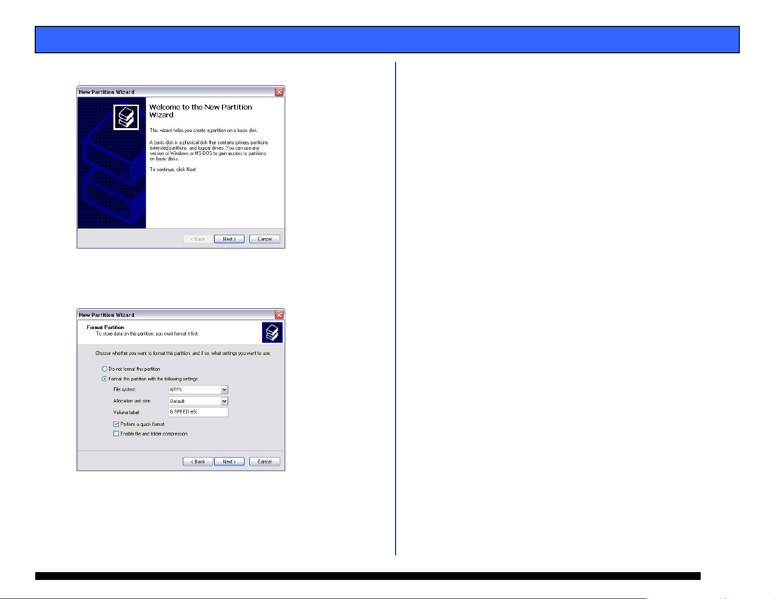
5. The “New Partition Wizard” will open, click <Next>.
6. Follow the prompts, ac
you reach this screen, en
S le
e ct “Perform a quick form
cepting the default values. When
e
t r the values as shown.
at” and then click <Next>.
(This page left intentionally blank)
7. he Wizard will complete and bring you back to t e Main
T h
isk Management screen. The G-SPEED eS will format in
D
ust a few seconds and be ready to use!
j
Pa
Pa e 28
 Loading...