

Page 1
G-SPEED eS INSTALLATION GUIDE
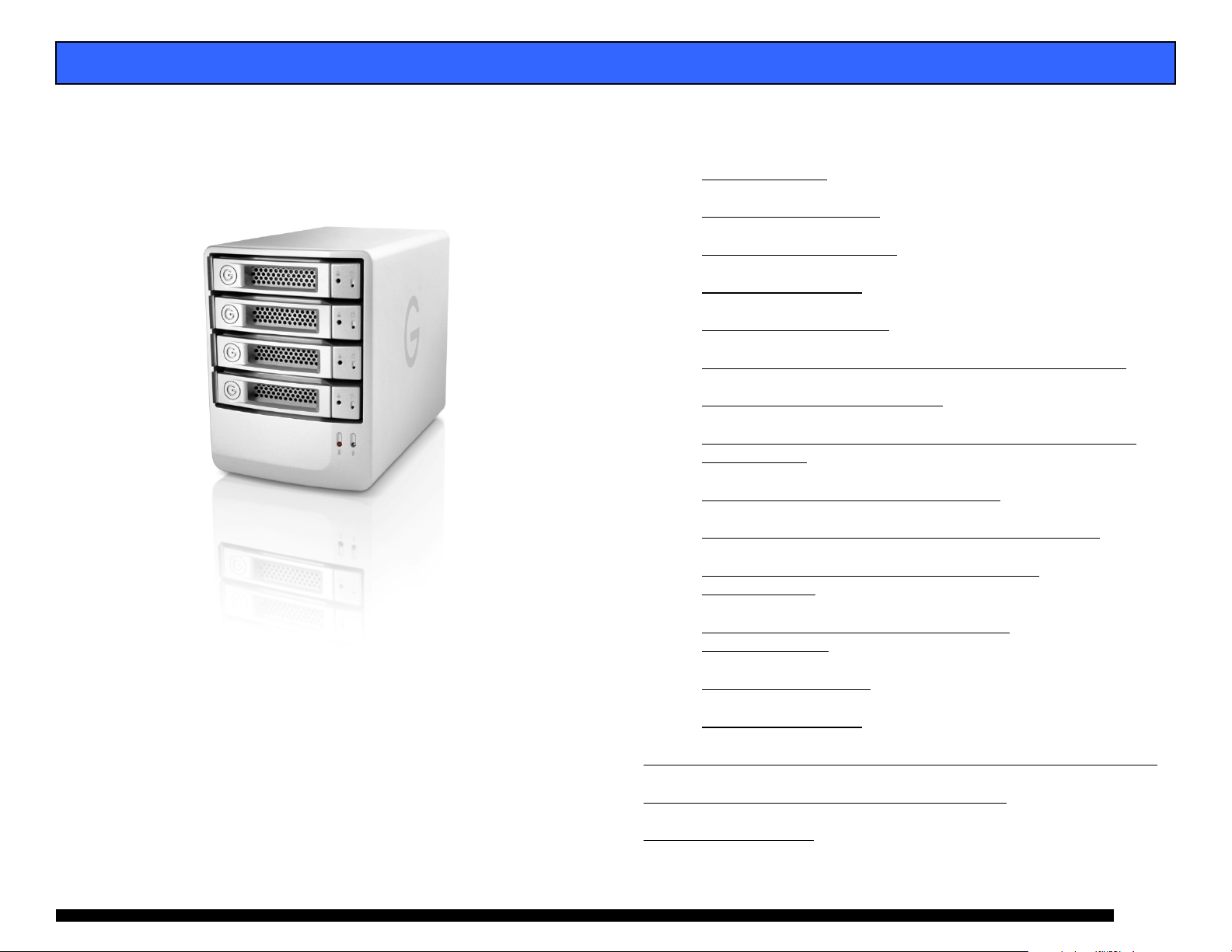
G-SPEED™ eS
Mac Installation Guide
G-Technology Inc.
Tel: (310) 449-4599
Fax: (310) 449-4670
support@g-technology.com
P/N GSPEED eS v1.2
TABLE OF CONTENTS
1. INTRODUCTION (Pg 4)
2. SAFETY PRECAUTIONS
3. SYSTEM REQUIREMENTS
4. WHAT’S IN THE BOX
5. G-SPEED eS OVERVIEW
6. OPTIONAL G- TECH PCIe RAID CONTOLLER OVERVIEW
7. G-SPEED eS AUDIBLE ALARMS
8. SETTING UP G-SPEED eS WITH THE G-TECH PCIe RAID
CONTROLLER
9. G-TECH RAID CONTROLLER WEB GUI
10. CHANGING THE G-TECH RAID CONTROLLER MODE
11. CONFIGURING TWO G-SPEED eS UNITS IN
RAID 5 MODE
12. WHAT TO DO IN THE EVENT OF A DISK
DRIVE FAILURE
13. TECHNICAL SUPPORT
14. LIMITED WARRANTY
APPENDIX A – DETAILED INFORMATION ON USING THE WEB GUI
APPENDIX B – EXPLANATION OF RAID LEVELS
APPENDIX C – NOTES
(Pg 11)
(Pg 15)
(Pg 5)
(Pg 6)
(Pg 8)
(Pg 9)
(Pg 17)
Page 1
Page 2
G-SPEED eS INSTALLATION GUIDE
Page 2
Page 3
G-SPEED eS INSTALLATION GUIDE
Page 3
Page 4
G-SPEED eS INSTALLATION GUIDE
1. INTRODUCTION
Thank you for purchasing G-SPEED eS from G-Technology,
Inc. (G-Tech)! Specifically designed for professional content
creation applications, G-SPEED eS features a high-speed
3Gbit/sec eSATA interface and provides RAID 0, 1, 5, 10 and
JBOD functionality when used in conjunction with the optional
G-Tech PCI Express (PCIe) RAID controller. Up to four
G-SPEED eS units can be attached to the G-Tech RAID
controller for storage capacities to 16 TB and data rates over
600 MB/sec. G-SPEED eS supports multi-stream video editing
workflows on Mac Pro workstations.
If you purchased G-SPEED eS with the G-Tech PCIe
RAID controller, the system has been set up at the
factory in RAID 0 mode. The controller also supports
RAID 1, 5, 10 and JBOD modes. Refer to Section XX if you
wish to change the mode of operation.
2. SAFETY PRECAUTIONS
The disk drives contained in your G-SPEED eS are delicate
electronic instruments and are susceptible to damage due to
excessive physical shock. Place the unit in a vented area away
from moisture or liquids. Please handle the unit with care. Do
not open the case. Doing so will void the warranty. If the
Product is returned with damage caused by improper
handling, the warranty will be void and liability will rest with
the user.
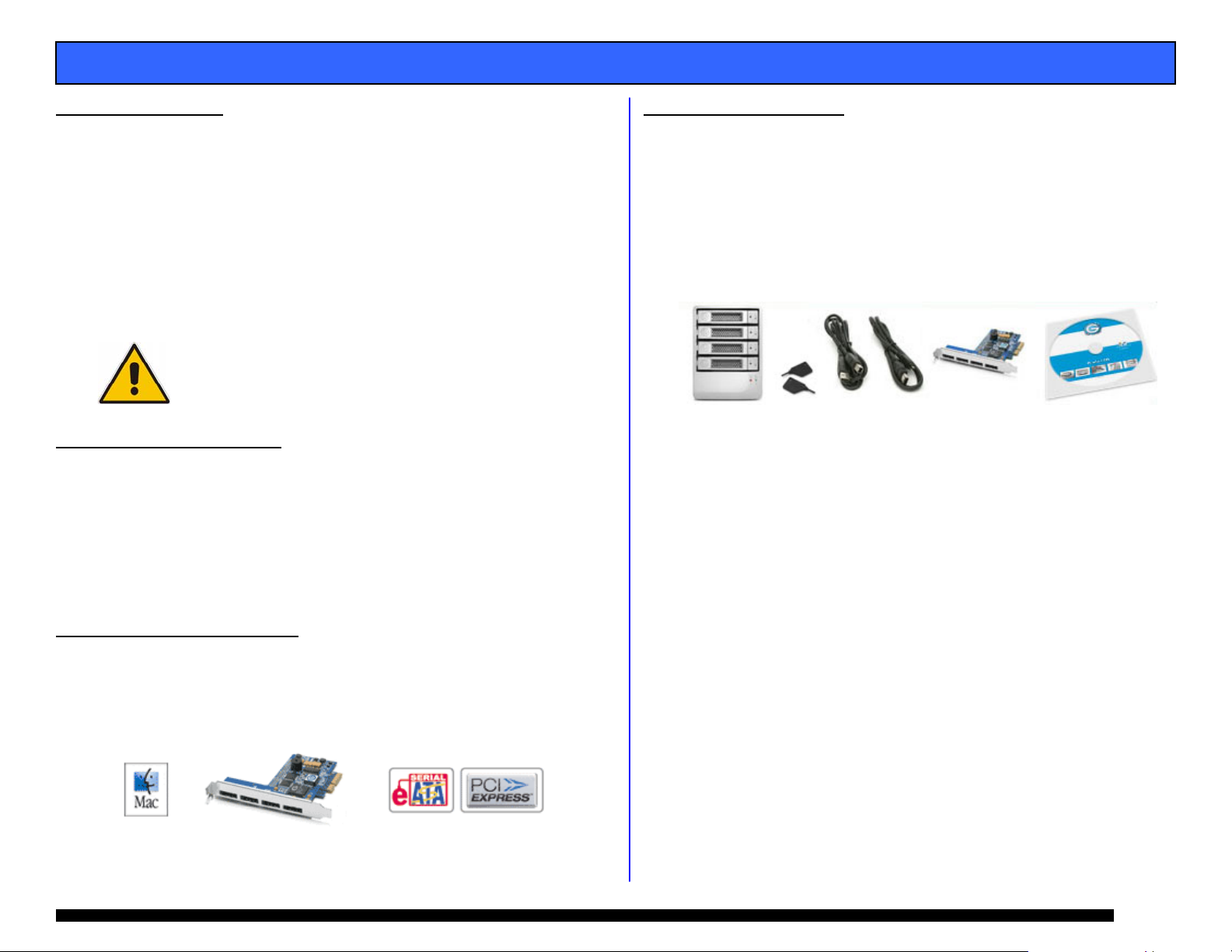
3. SYSTEM REQUIREMENTS
• Apple Mac Pro (Intel Mac) workstation
• Mac OS X 10.4.x or higher
• G-Tech PCIe RAID Controller or third party port multiplier
aware eSATA host adapter
Optional G-Tech 4-port,
PCIe x4 RAID Controller
4. WHAT’S IN THE BOX
Take a moment to ensure that the following items are
included in the box. If anything is missing, please call G-Tech
at (310) 449-4599. Please keep the shipping container and
packing materials. In the unlikely event that you need to
return G-SPEED eS to us for any reason, you must use the
G-Tech shipping container. If the Product is returned
damaged caused by improper packaging, the warranty will be
void and liability will rest with the user.
• G-SPEED eS storage system
• 4 removable SATA drive modules (installed in unit)
• (2) disk module keys
• 1-meter eSATA cable
• AC Power cable
• Optional – G-Tech PCIe RAID controller
• Configuration Utility & Installatio n CD
Page 4
Page 5
G-SPEED eS INSTALLATION GUIDE
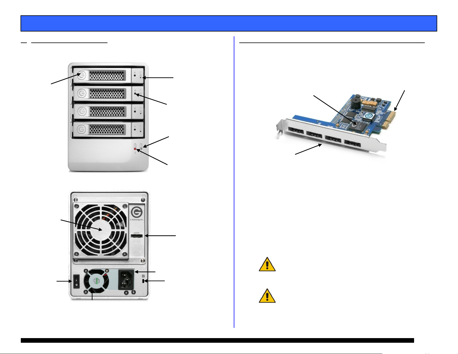
5. G-SPEED eS OVERVIEW
(4) Removable
Disk Drive Modules
Removable
Fan
ON/ OFF
Switch
6. OPTIONAL G-TECH PCIe RAID CONTOLLER OVERVIEW
The optional G-Tech PCIe RAID controller connects
G-SPEED eS to any Mac Pro workstation and provides
Drive Module
Power/Activity
LED
Disk Module
Lock Hole
Power Supply
LED
Temperature/Fan RPM
Warning LED
3 GB/sec
eSATA
Port
AC Input
Cable Lock
Hole
RAID 0, 1, 5, 10 & JBOD functionality.
RAID Engine
(4) High-speed
3 Gb/s eSATA ports.
Supports up to (4)
G-SPEED eS systems
PCIe x4 interface
6.1 Supported RAID Levels
If your G-SPEED eS shipped with the optional G-Tech
PCIe RAID controller, the system was configured as a
RAID 0 at the factory. The controller also supports
RAID 1, 5, 10 and JBOD configurations. If you wish to
change the RAID mode, please refer to Section 10.
For an explanation of supported RAID levels, please
refer to Appendix B.
If you purchased G-SPEED eS with the G-Tech PCIe
RAID controller, the system has been set up at the
factory in RAID 0 mode. The controller also supports RAID
1, 5, 10 and JBOD modes. Refer to Section 10 if you wish to
change the mode of operation.
G-SPEED eS is also compatible with third-party Mac &
Windows port multiplier aware eSATA host adapters. Refer to
your host adapter documentation to set up
G-SPEED eS with these boards.
Page 5
Page 6
G-SPEED eS INSTALLATION GUIDE
7. G-SPEED eS AUDIBLE ALARMS
7.1 The G-SPEED eS enclosure is equipped with an audible
alarm that sounds when:
1. The internal temperature of the G-SPEED eS enclosure
reaches a temperature of 60° centigrade
and/or
2. When the main FAN fails or the RPM of the fan slows to
a state where the fan can longer adequately cool the
system.
In addition to the audible alarm, the Temperature/Fan
Warning LED located on the front bezel of G-SPEED eS
will illuminate.
If you hear an audible alarm and see the RED warning LED on
the front of G-SPEED eS, stop using G-SPEED eS immediate ly.
Check to see if the fan is spinning and move the unit to a
cooler location. If you require a new fan, contact G-Tech
Support for a replacement.
7.2 The G-Tech RAID controller is also equipped with an
audible alarm that sounds when:
1. A disk drive failure occurs
or
2. When the G-SPEED eS is removed from the RAID
controller without first selecting “Unplug” in the Array
Maintenance menu in the web GUI.
If you hear an audible alarm coming from the G-Tech RAID
controller, see Section 12 “What to do in the Event of a Disk
Drive Failure”. See Appendix A.1.7.2 for information on the
proper way to hot “Unplug” G-SPEED eS.
8. SETTING UP G-SPEED eS WITH THE G-TECH PCIe
RAID CONTROLLER
G-SPEED eS comes pre-configured in RAID 0 mode and
formatted for MAC OS X. Connecting G-SPEED to your Mac
Pro and configuring your system takes just a few steps as
outlined below.
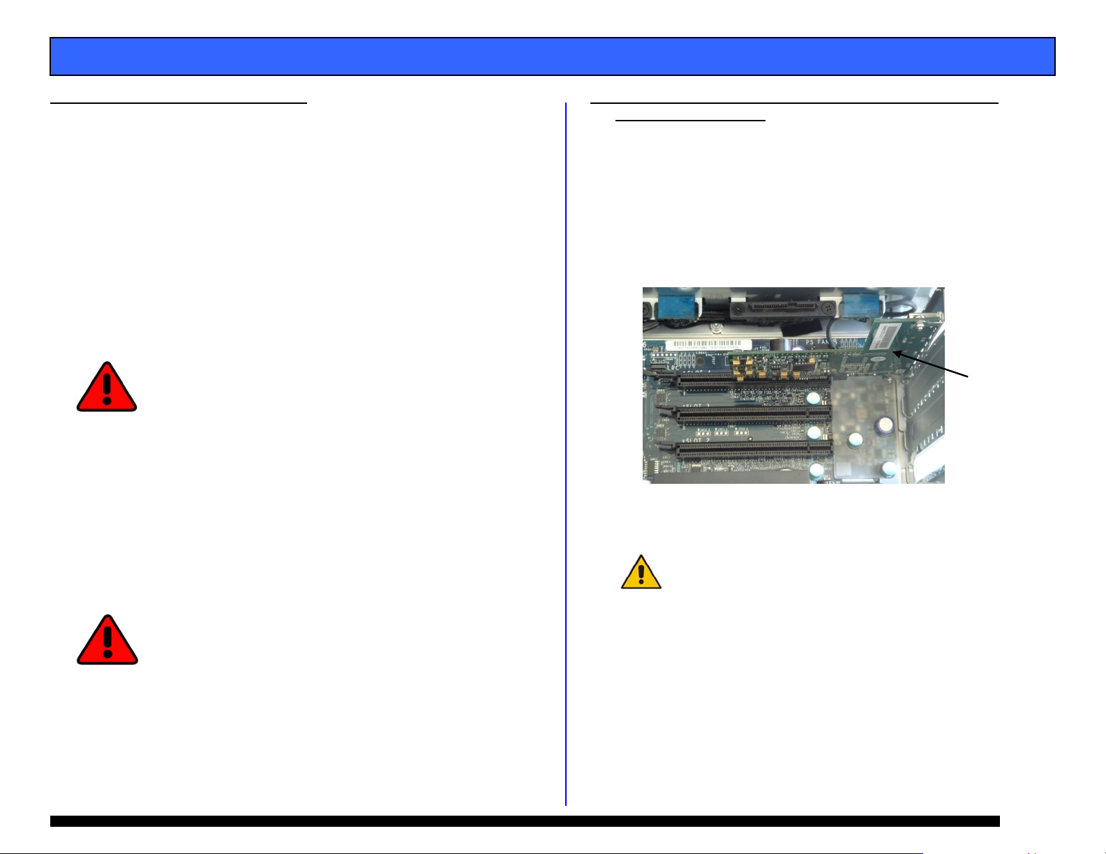
8.1 Installing the G-Tech PCIe RAID Controller
1. Install the G-Tech RAID controller into SLOT 4 (top slot)
of your Mac Pro workstation.
G-Tech PCIe
RAID Controller
2. Secure the RAID controller in place.
NOTE: If you are using an AJA, Blackmagic Design or
equivalent video capture card, install it in SLOT 3
unless otherwise instructed by the card vendor.
Page 6
Page 7
E
A
S
n
o
h
G
o
o
S
G
o
v
i
G
o
e
C
R
D
A
e
E
e
e
r
2 3
k
o
w
a
u
n
t
o
S
Th
B
o
e
o
S
a
f
p
o
l
t
o
t
w
g
G-SP
ED eS INST
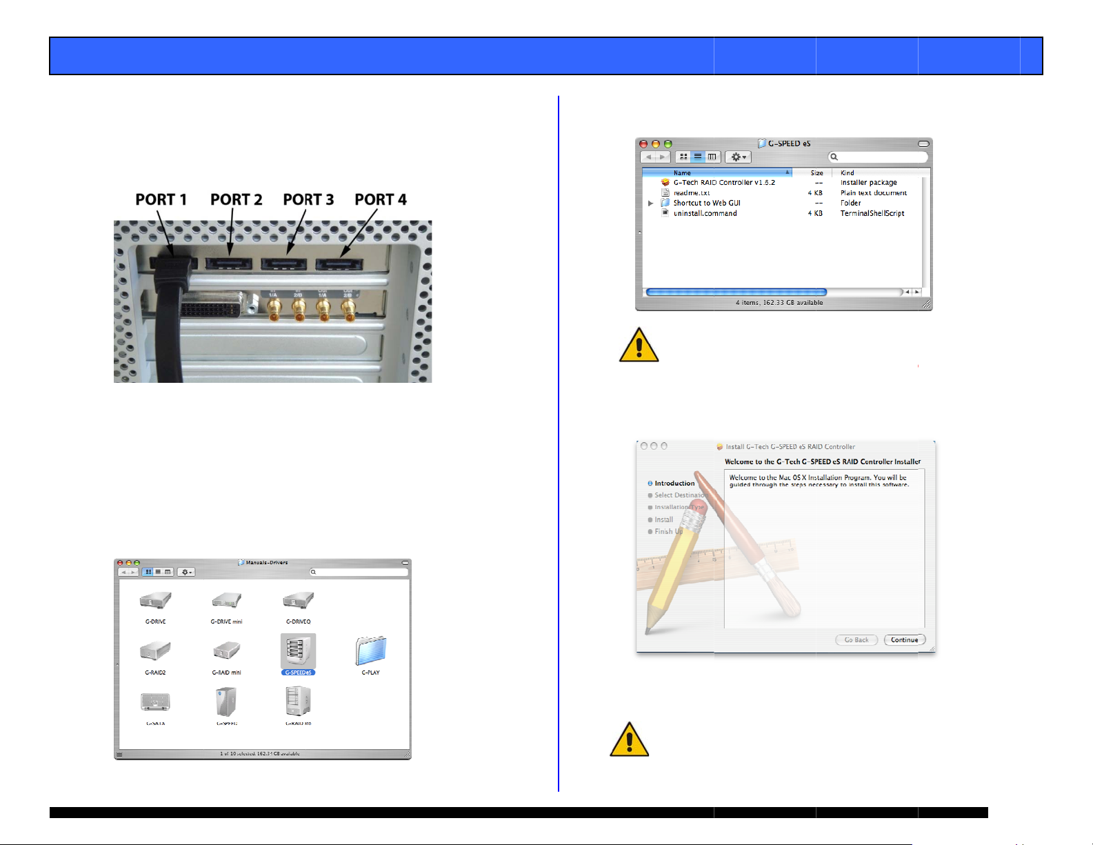
8.2
Attaching G-
1.
Attach one e
port located
2.
Attach the ot
port) on the
LLATION G
PEED eS to t
d of the suppl
n the back of
er end of the
-Tech RAID c
UIDE
he G-TECH R
ed eSATA cabl
-SPEED eS.
eSATA cable to
ntroller as sho
ID Controlle
to the eSATA
Port 1 (leftmo
wn below.
st
. Double-clic
package as
on the “G-Tec
shown below.
h RAID Contro
ler” installer
Check f
http://
If you
previo
r software updat
ww.g-technology.
re upgrading s
s version first.
s at
com/Support/
ftware you mus
ee section 8.4 f
un-install the
r details
3.
Attach the p
connect the
4.
Power on G -
wer cord to th
ther end to A
PEED eS.
back of G-SP
power.
ED eS and
. The followi
instructions
g window will
to load the so
ppear. Follow
tware.
the
Loading the
8.3
1.
Double-click
“Manuals-Dri
-Tech PCIe
n the G-SPEE
ers” folder on
AID Controll
eS icon locat
the included C
r Software
d in the
D as shown
below.
After restar
mount on y
Your Gmode.
10 and J
change the m
ing your syste
ur desktop.
PEED eS is ship
e G-Tech RAID c
OD modes. Refer
de of operation.
m, the G-SPEE
ed from the fac
ntroller also supp
to Section 10 belo
D eS will
ory in RAID 0
orts RAID 1, 5,
if you wish to
Pa
e 7
Page 8

E
EThmoaneq
A
t
o
v
a
N
D
P
r
e
e
/
g
c
W
t
o
C
n
E
b
m
i
e
d
0
d
e
t
t
d
o
a
o
o
t
w
a
n
a
o
d
I
h
3
n
h
t
n
n
r
d
A
d
r
0
<
o
g
G-SP
8.4
9. G-T
9.1
ED eS INST
Uninstalling
1.
Double-click
“Manuals-Dri
above.
2.
A Terminal wi
enter your p
GUI.
CH RAID CO
e G-Tech RAI
nitor the G-S
y web browse
uivalent.
Accessing th
1.
Open your w
https:/
2.
The followin
button.
NOTE: A short
“G-SPEED eS
SPEED eS\Shor
file from the D
icon to access t
LLATION G
he G-Tech P
n the uninstal
ers” folder on
ndow will ope
ssword to dele
TROLLER W
controller we
EED eS syste
such as Safar
G-Tech PCI
b browser an
localhost:74
window will
ut has been provi
eb GUI” file (locat
cut to Web GUI)
cuments folder to
he web GUI.
UIDE
Ie RAID Con
l.command file
the included C
and you may
te the installe
B GUI
GUI is used t
. The GUI is
, Internet Expl
RAID Contr
enter the foll
2
appear. Click
ed to access the
d in the folder M
o your Documents
the dock as show
roller Softw
located in the
D as shown
be prompted t
driver and we
configure an
ccessed using
orer or
ller Web GU
wing address:
he <Continue
eb GUI. Drag the
nuals-Drivers\G-
folder. Drag the
below. Click on t
re
b
>
e
. The followi
Enter “adm
zeros) as t
g will appear i
in” as the Use
e Password an
your browse
Name and “0
click on the
window.
00” (four
Login>
button.
No
e: See appendix
cha
ging the passwor
.4.5 for instructi
ns on
Pa
e 8
Page 9

E
A
e
o
n
e
h
E
I
o
a
f
C TcJcc
10. 123
H
h
r
d
r
S
G
“
D
A
e
o
o
E
m
R
I
i
o
d
g
n
o
G-SP
ED eS INST
4.
The main scr
below. Note t
Each of the f
lower Sectio
LLATION G
en of the web
hat the G-SPE
ur drives in th
of the GUI.
UIDE
GUI will appe
D eS is set up
e unit are displ
r as shown
as a RAID 0.
ayed in the
10.
HANGING T
he G-SPEED e
onfigured at t
BOD modes a
hange the mo
hange modes.
E G-TECH RA
S/G-Tech RAI
e factory in R
e also availabl
e of operation
ID CONTOLL
controller co
ID 0 mode.
. The web GU
. Follow the d
R MODE
bination is
AID 1, 5, 10 a
is used to
rections below
d
to
1 Changing f
. Unmount G-
om RAID 0 t
PEED eS by d
RAID 5
ragging the ic
n to the trash.
. Launch the
. Click on the
will appear.
-Tech RAID C
Maintenance”
ntroller web G
Link. The win
UI.
ow shown bel
w
NOTE: Pleas
features of t
refer to APPEND
e G-Tech RAID C
X A for detailed in
ntroller web GUI.
ormation on the
Pa
e 9
Page 10

E
A
<
C
W
r
C
t
e
e
e
d
7
D
y
n
b
T
F
”
<
a
1
A
-
n
o
u
D
ge
k
G-SP
ED eS INST
LLATION G
UIDE
4.
Click on the
will appear.
5.
The GUI will
DELETE> but
lick the <OK>
ARNING: This wil
ored on G-SPEED
st
efresh and th
on. The followi
button to proc
l delete any data
S!
array is now
ng window
ed.
eleted.
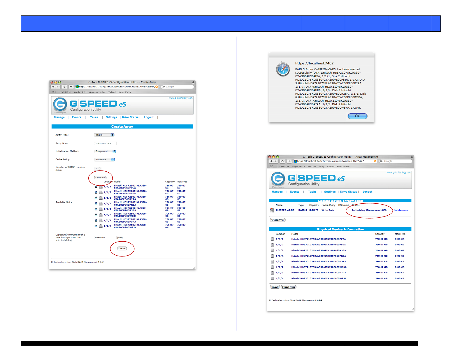
. Select RAI
for “Array N
for “Initializ
respectivel
5 for “Array
ame:”, select
ation Method:
and click the
ype:”, enter G
oreground a
and “Cache P
Select All> b
SPEEDeS-R5
d Write Bac
licy:”
tton.
NOTE: I
can also
appropria
this example we
e set up in RAID
te setting in the “
re creating a RAI
, 10 or JBOD mod
rray Type:” pull-d
5. The system
e by selecting the
own menu.
6.
Click the <
window will a
reate Array>
ppear.
button. The
“Create Array”
Pa
10
Page 11

E
C
C
T
Tpc
“
A
a
>
d
t
c
G
r
h
f
e
e
e
n
o
o
o
A
a
C EGJcc
G
S
t
e
s
G
o
r
d
G-T
o
n
h
a
u
m
h
S
b
y
E
D
e
r
T
A
n
u
w
o
i
n
I
a
I
I
i
e
T
n
ge
d
s
O
d
e
G-SP
ED eS INST
8.
lick the <Cre
9.
lick the <OK
he GUI will in
LLATION G
te> button. T
button. The
icate that the
UIDE
e following wi
ollowing wind
G-SPEED eS is
dow will appe
w will appear.
initializing.
r.
1
1. The Mac O
11.
ONFIGURIN
indicating
Click on th
Utility and
instruction
will display t
he G-SPEED e
<Initialize>
refer to your s
.
TWO G-SPE
e “Disk Insert
is now ready
utton to launc
stem docume
D eS UNITS
on” window
to be initialize
h the Apple Di
tation for
N RAID 5 M
.
k
DE
10.
he RAID 5 ini
er TB of final
omplete, the
Status” as No
ialization proc
apacity. Onc
UI will indicat
mal .
ss takes appr
the initializati
“Type” as R
ximately 1:45
n process is
ID 5 and
ach G-SPEED
-Tech RAID c
BOD modes a
hange the mo
onfigure two
ech RAID c
1. Ensure tha
installed a
2. Attach bot
controller
your comp
3. Both syste
eS unit is confi
ntroller in RAI
e also availabl
e of operation
-SPEED eS ar
ntroller.
t the G-
d the driver a
G-SPEED eS
s shown belo
ter
s will mount
ech R
gured at the f
0 mode. RA
. The web GU
. Follow the d
ays in RAID 5
ID controller i
d web GUI ar
nits to the G-
, power the u
n the desktop
ctory with the
D 1, 5, 10 an
is used to
rections below
mode using th
s properly
loaded.
ech RAID
its and restart
.
to
Pa
11
Page 12

E
Ut
Lud
A
T
t
a
n
R
g
.
,
s
e
A
i
S
w
ge
S
a
G-SP
ED eS INST
4.
nmount both
he trash.
5.
aunch the Gnits attached
isplay inform
LLATION G
G-SPEED eS u
ech RAID Cont
o the G-Tech
tion like that s
UIDE
its by draggin
roller web GUI
AID controller
hown below.
the icons to
With the two
the GUI will
6.
Click on the “
Name” GS Di
Maintenance” l
k 1_0. The w
ink next to the
ndow shown b
array with “O
elow will appe
r.
7.
Click the <D
lete> button.
The following
indow
will appear.
W
NING: This will
sto
red on G-SPEED e
delete any data
.
Pa
12
Page 13

E
A
K
s
e
A
o
e
e
e
w
S
1
2
<
C
b
s
C
ge
G-SP
ED eS INST
LLATION G
UIDE
8.
Click the <O
Click on the “
9.
Name” GS Di
> button to d
Maintenance” l
k 1_1. The w
lete the array.
ink next to th
indow below w
array with “O
ill appear.
1
. Click the
arrays hav
OK> button
e now been
to delete the
deleted as
array. Both
hown below.
. Click the <
1
window will
reate Array>
appear.
utton. The “
reate Array”
Pa
13
10.
Click the <D
lete> button
and the follo
ing window w
ill
appear.
W
st
RNING: This will
red on G-SPEED
delete any data
S.
Page 14
E
A
t
a
e
t
h
S
S
h
t
415
n
O
t
a
h
E
z
ge
r
G-SP
ED eS INST
13.
Select RAID
R5 for “Array
Back for “Ini
respectively
Click the <Cr
LLATION G
5 for “Arr a y Ty
Name:”, selec
ialization Met
nd click the <
ate> button.
UIDE
pe:”, enter G-
Foreground
od:” and “Cac
elect All> but
PEED-eS-
and Write
e Policy:”
on then
1
. The followi
. Click the <
to indicate
g window will
K> button. T
hat the G-SPE
ppear.
e following wi
D eS is initiali
ndow will appe
ing.
a
Pa
14
Page 15

E
HTheafai
o 1
2
A
n
a
e
N
w
e
<
f
d
n
d
a
o
c
a
s
t
t
O
t
E
u
h
s
v
b
g
p
R
n
t
a
I
n
r
e
o
d
o
e
4
f
k
T
d
m
o
a
t
C
Te
e
a
h
r
t
ge
n
G-SP
15.
16.
12. W
ED eS INST
The RAID 5 i
per TB of fin
complete, th
“Status” as
The Mac OS
indicating th
Click on the
Utility and re
instructions.
AT TO DO IN
e G-Tech RAID
ch of the disk
lure, an audibl
re
port the failed
NOTE:
RAID m
result i
unprote
replace
F
llow the steps
. Launch the
. Mute the al
button.
LLATION G
itialization pr
l capacity. On
GUI will indic
ormal.
ill display the
G-SPEED eS i
Initialize> bu
er to your sys
THE EVENT
controller con
rives in G-SP
e alarm will so
drive and its p
If G-SPEED eS wa
ode (RAID 1, 5 or
data loss. Howe
cted state and the
as soon as possi
below to identi
web GUI.
rm by clickin
UIDE
cess takes ap
e the initializa
te “Type” as
“Disk Insertio
now ready to
ton to launch
em document
F A DISK DR
inually monito
ED eS. In the
nd. The web
ysical positio
configured in a p
10), a drive failur
er, the array is n
failed drive shoul
le to avoid data l
fy and replace
on the <Beep
roximately 1:
tion process is
AID 5 and
” window
be initialized.
he Apple Disk
tion for
VE FAILURE
rs the health o
event of a dis
GUI will also
.
otected
does not
w in an
be
ss.
a failed drive.
r Mute>
5
he GUI will
exclamation
the “Status”
the GUI indic
isplay informa
ark on the G-
f the array is
tes which driv
tion like that s
SPEED eS icon
ritical. The lo
e in which G-S
own below. A
indicates that
wer portion of
PEED eS unit
has failed.
In
his example there
con
nected to the G-
the
G-SPEED eS conn
RAI
D controller has f
are two G-SPEED
ch RAID controlle
cted to Port 2 of
iled.
eS units
. Drive 3 of
he G-Tech
Pa
15
Page 16

E
3
A
e
S
b
e
R
e
w
e
e
e
l
G
h
I
G
u
S
h
e
d
e
o
i
R L
S
h
w
a
r
W
R
E
w
h
t
i
o
e
p
y
I
T
k
u
e
d
ge
,
G-SP
ED eS INST
LLATION G
UIDE
. Remove th
G-SPEED e
controller)
hole and g
enclosure.
X
WA
drive
conn
follo
conn
failed drive (I
connected to
y inserting th
ntly sliding th
NING: Make abso
indicated by the
cted to the G-Tec
the cable to ensu
cted to on the RA
n this example
port 2 of the
provided key
drive module
utely sure that yo
UI. If multiple G-
RAID controller,
re you know whic
D controller.
Drive 3, of th
-Tech RAID
in to the lock
out of the
remove the faile
PEED eS units ar
it is a good idea t
Port # the array
EMOVING THE
OSS OF THE AR
TORED ON G-SP
RONG DRIVE W
AY AND ALL OF
ED eS.
LL RESULT IN T
HE CONTENT
E
4. Replace t
secure in
the GUI
“Status” s
complete)
approxim
e failed drive
place. Once t
ill indicate tha
hows Rebuild
as shown bel
tely 2 hours p
ith a new dis
e drive has sp
the array is r
ng and the pe
w. The rebuil
r TB.
module and
n up to speed
building (The
rcentage
time is
5. Once the
Normal a
ebuild is com
nd protecting
lete, G-SPEED
our valuable d
eS is back to
ata once again
.
s
Pa
16
Page 17

G-SPEED eS INSTALLATION GUIDE
13. TECHNICAL SUPPORT
If you encounter any difficulties while installing G-SPEED,
please contact G-Tech Technical Support via one of the
following ways:
Telephone: (310) 449-4599
Fax: (310) 449-4670
E-mail: support@g-technology.com
Internet: http://www.g-technology.com/support
When contacting Technical Support, make sure to be in front
of your computer and have the following information readily
available:
• Your G-SPEED eS serial number (on bottom of unit)
• Operating system and version
• Computer brand and model
• eSATA host adapter brand and model
• Amount of memory installed
• Other devices attached to your computer
Thank you for purchasing G-SPEED eS. If you have any
comments or questions about this manual or the Product,
please call (310) 449-4599, or send an email to
info@g-technology.com
.
14. LIMITED WARRANTY
G-Technology Inc. (G-Tech) warrants your Product against
any defect in material and workmanship, under normal
use, for the designated warranty period. If the Product
should become defective within the warranty period,
G-Tech, will at its discretion, repair or replace the Product.
Repair or replacement parts or Products will be furnished
on an exchange basis and will be either new or
reconditioned. All replaced parts or Products shall become
the Property of G-Tech. This warranty shall not apply if the
Product has been damaged by accident, misuse, abuse or
as a result of unauthorized service or parts. Warranty
service is available to the purchaser by obtaining a Return
Material Authorization number (RMA) and by delivering
the Product during the warranty period to an authorized
G-Tech service facility or to G-Tech. The purchaser shall
bear all shipping, packing and insurance costs and all
other costs, excluding parts and labor, necessary to
effectuate repair, replacement or refund under this
warranty. All returned Product must be shipped to
G-Tech in the original shipping container.
For more information on how to obtain warranty service,
an RMA number or to acquire shipping materials, contact
G-Tech at 1653 Stanford Street, Santa Monica, CA 90404,
(310) 449-4599 or support@g-technology.com
IN THE EVENT A PRODUCT BECOMES DEFECTIVE DURING
THE WARRANTY PERIOD, THE PURCHASER’S EXCLUSIVE
REMEDY SHALL BE REPAIR OR REPLACEMENT AS
PROVIDED ABOVE. INCIDENTAL OR CONSEPROUENTAL
DAMAGES, INCLUDING WITHOUT LIMITATION LOSS OF
DATA, ARISING FROM BREACH OF ANY EXPRESS OR
IMPLIED WARRANTY ARE NOT THE RESPONSIBILITY OF GTECH AND, TO THE EXTENT PERMITTED BY LAW, ARE
HEREBY EXCLUDED BOTH FOR PROPERTY DAMAGE, AND
TO THE EXTENT NOT UNCONSCIONABLE, FOR PERSONAL
INJURY DAMAGE.
.
Page 17
Page 18

E
E
123
456
A
B
s
G
a
H
t
o
b
s
e
n
.
t
a
e
m
m
e
P
f
d
e
a
m
t
t
e
x
i
n
e
d
n
t
”
a
e
c
n
o
R
s
t
A
A
y
P
D
x
m
n
D
a
a
l
i
v
a
r
n
e
g
f
e
m
a
a
n
ge
G-SP
APP
ED eS INST
NDIX A: WE
LLATION G
GUI
UIDE
A.1 Manage:
rray
. Manage:
Array: Thi
web GUI.
from this p
Devices:
page (you
page as
performanc
Spare Po
drives can
called hot
added to th
. Events: All
recorded h
These eve
notification
. Tasks: Sch
automatical
volume.
. Settings:
settings s
notification
. Drive Sta
hard drives
. Logout: S
is the main
-SPEED eS is
ge. (See App
ard drive para
should not
he drives ar
e with the G-S
l: When con
e assigned to
pare). These
e Array in the
events of the
re, such as
ts can be e
under the “Se
edule the G-Te
ly verify the in
Configure th
uch as logi
See Appendi
us: Check th
including deta
y goodbye
screen of the
configured a
ndix A.1 for d
eters are mo
ake any cha
configured
EED eS.
igured in pro
a “spare pool
rives will be
vent of a driv
G-SPEED eS
rray changes
ailed by setti
tings” tab.
ch controller t
egrity of the
G-SPEED e
n password
A.4 for detail
e status of a
led SMART da
G-SPEED eS
d monitored
tails)
ified on this
ges on this
for optimal
ected mode
(sometimes
utomatically
failure.
ontroller are
and failures.
g up email
AID
S controller
and email
ll connected
a.
1. Name:
2. Type: Di
3. Capacit
4. Cache
for RAI
appendi
5. OS Na
display i
6. Status:
Norm
Critic
Initia
Rebu
rray name (as
splays RAID le
: you guessed
olicy: Display
protected
A.1.7.7
e: Controlle
Disk Utility.
isplays curre
l: All OK
l: Drive failur
izing: Buildin
lding: Parity d
shown in GUI
el of array.
it… capacity o
s current writ
rrays. For
assigned n
t status of arr
has occurred
RAID 1, 5 or
ata being reco
only).
the array.
cache policy
ore info see
me that will
y.
10 array
structed
Pa
18
Page 19

E
A
e
u
l
D
N
A
B
g
m
e
h
t
L
s
n
p
e
t
S
a
e
A
a
p
e
T
A
h
h
y
a
L
o
e
A
e
n
c
e
C
.
b
.
t
t
m
r
o
r
d
a
s
e
_
C
r
g
u
o
y
m
t
s
t
v
D
T
h
p
t
t
ge
h
r
G-SP
ED eS INST
LLATION G
UIDE
Maintenanc
7.
options for c
on RAID leve
RAID 0
7.1 Delete:
7.2 Unplug
controller.
system befor
to be unplu
alarm.
7.3 Rename
: Displays con
rrent array. T
of the array.
eletes curren
WAR
THE
ING: THIS
RRAY AND A
: This will di
e sure to u
e using this o
ged from th
NOTE:
recom
disconn
While the con
end shutting the
cting G-SPEED e
: Renames arr
figuration and
e options diff
Array
OPERATION
L DATA ON I
connect the
mount all vol
tion. This en
system with
roller is “hot
system down whe
from the controll
y as displayed
maintenance
r depending
WILL DELE
T!!
rray from t
umes from t
bles the arra
out causing
luggable,” we
n connecting or
r.
in the GUI.
E
e
e
s
n
7.4 OCE/OR
Online Ca
capacity
G-SPEED
Online R
the RAID
7.5 Shows th
location a
“Devi
RAID 5
7.6 Verify: V
7.7 Change
RAID 5 arrays
Write-
cached
but da
failure.
Write-
always
reads
approp
M:
pacity Expansi
f an existing a
S units are a
ID Level Migr
level of an exi
devices curr
d status.
e
ontrolle
rifies the inte
ache Policy:
ack: Data
This will res
a loss may
hrough: Dat
passed directl
ay still be co
iate
n: It is possib
ray when addi
ded to the sys
tion: it is pos
ting array.
ntly part of
#_Port#_Dri
rity of the RAI
his option is
written to t
lt in higher
ccur in case
a written to
to the disks.
pleted from
le to expand t
tional
em.
ible to change
he Array, thei
#”
set.
available for
e array is
erformance,
of a power
he array is
Subsequent
he cache, if
e
Pa
19
Page 20

E
C
C
A
e
e
m
a
o
o
u
p
u
e
e
T
c
r
n
e
u
c
D
c
b
D
s
o
A
e
l
h
n
t
i
t
k
d
y
i
h
#
t
s
e
w
i
a
t
o
y
a
a
t
o
i
n
d
c
e
p
u
i
ge
d
h
t
e
o
G-SP
8.
ED eS INST
reate Array
lick on “Create
LLATION G
Array” and th
UIDE
following will appear.
8
.1 Array Typ
8
.2 Array Na
the MAIN p
8
.3 Initializati
creation pr
Foregro
creation
: select the R
e: This is the
ge of the GUI.
n Method: S
cess.
nd: All contro
rocess and t
ID level for ne
name that w
ts the priority
ler resources
e array is no
array
ll be displaye
of the RAID
re used for t
available un
in
e
il
complete.
Backgro
for the cr
immediat
nd: Minimal
ation process
use.
NO
E: RAID protectio
unti
l initialization is co
controller res
and the arra
n is not available
mplete
urces are us
is available f
d
r
8
.4 Cache Poli
a RAID 5 a
Write-back
will result i
occur in cas
Write-thro
passed dire
still be comp
y: This optio
ray.
: Data written
higher perfor
of a power fa
gh: Data wri
tly to the dis
leted from the
is available w
o the array is
mance, but d
lure.
ten to the arr
s. Subsequen
cache, if appr
hen creating
cached. This
ta loss may
y is always
reads may
priate
8
.5 Select All:
8
.6 Available
for array
serial num
Simple metho
isks: Displa
reation, show
er, size of t
to select all d
s disks curre
ng location,
he disk and
sks.
tly available
rive model,
urrent free
capacity.
Location:
“Controller
/Port#/Driv
”
8
.7 Available
new array.
available.
8
.8 Create: A
array creati
isks: Enter
Default i
expected, s
n process.
he desired ca
the Maxim
lecting this w
acity of the
m capacity
ll begin the
Pa
20
Page 21

E
o
o
odis
a
adis
ede
e
A
w
r
s
t
a
e
t
n
M
e
“
h
o
/
o
c
o
m
c
e
w
n
e
o
a
t
a
n
e
n
ge
G-SP
ED eS INST
LLATION G
UIDE
9. L
10. M
11. C
12. M
13. R
14. B
cation: Sho
co
ntroller.
L
cation: “Cont
del: Display
ks currently a
pacity: Displ
cu
rrently attach
x Free: Disp
ks currently a
scan: Resca
vices attached
eper Mute:
NOTE: Beep
disconnected
Unplug” in t
s the location
oller#/Port#
the drive m
tached to the
ys the adverti
d to the contr
lays the maxi
tached to the
s the eSATA
.
utes audible b
r will sound when
from the system
e Array Maintena
f disks attach
Drive#”
del and serial
ontroller.
sed capacity
ller.
um free cap
ontroller.
bus to detec
eper.
a drive fails or an
ithout first selecti
ce menu.
d to the
number of
f the disks
city of the
any new
rray is
g
(This page left int
ntionally bla
k)
Pa
21
Page 22

E
A
d
e
t
e
r
s
o
b
s
C
n
t
A
e
S
a
e
a
r
u
u
r
b
r
r
c
p
r
e
t
m
v
a
t
h
o
5
n
o
e
i
u
o
n
s
n
s
ge
G-SP
ED eS INST
LLATION G
UIDE
pendix A.4: S
Ap
ettings
1.
Auto Rebuil
feature. Wh
array will au
inserted. Se
: Enables o
n enabled, a
omatically re
Section 12 fo
disables the
critical RAID
uild when a
details.
auto-rebuild
or RAID 1
ew drive is
2.
Audible Ala
m: Enables o
disables the a
udible alarm
3.
SAF-TE: Thi
feature is not
currently supp
rted.
4.
Listening P
G-SPEED we
network user
rt: The port
GUI. “Restri
to access the
used to con
t to local acc
GUI. Default
nect to the
ss” disables
s Port 7402.
5.
Password:
6.
SMTP Setti
for email no
here.
hanges login
g: Email se
ification. Ent
assword. Defa
ver informati
r your server
lt is 0000
n necessary
information
Recipients:
7.
list of curren
email recipie
ts.
Add Recipi
8.
notification.
Information
Warning: W
Error: Error
nt: Add e
elect Event le
: Informationa
rning events
vents are sen
ail addresse
el to trigger a
l events are se
re sent
for email
n email.
nt
Test: Sends
test email to
the new accou
t
HDD Tempe
9.
of the hard
email. Defa
can operate
ature Thres
drive tempera
lt is 50°C, h
p to 60°C.
old: Adjusts t
ture to trigge
wever today’
he threshold
r a warning
disk drives
Pa
22
Page 23

G-SPEED eS INSTALLATION GUIDE
APPENDIX B: RAID levels explained
RAID
Level Description Advantage Disadvantage Ideal For…
0 Disk striping Offers the highest
1 Mirroring Maximum level of
5 Disk striping
with
distributed
parity
10 Mirror of
striped drive
pairs
JBOD Just-a-
bunch-ofdisks
performance and a
useable storage
capacity of 100%
of total available
storage capacity
data protection as
identical data is
written to multiple
drives
High read
performance,
medium write
performance with
data protection in
case of a drive
failure.
Higher
performance than
RAID 1 with same
level of data
protection.
Each drive can be
accessed as an
individual volume.
Useable storage
capacity is 100%
of total available
storage.
No fault tolerance failure of one drive
in the array results
in complete data
loss
Useable storage
space is 50% of
total available
capacity
Useable storage
capacity equals
total capacity of all
drives in the array
less the capacity of
one drive.
For example, a 4x
1TB RAID 5 yields
a useable capacity
of 3 TB.
Disk failure results
in drop in
performance
Useable storage
space is 50% of
total available
capacity
No fault tolerance Audio
Content creation
applications
requiring highest
storage capacity
Applications in
which data
security is
paramount
Content creation
applications
requiring data
protection
Content creation
applications
requiring data
protection
applications
APPENDIX C: Notes
When the G-Tech web GUI is open dropped frames
may occur in editing applications such as Final Cut
Pro. We recommend not having the GUI open while
working in these programs.
It is recommended not to exceed the standard eSATA
cable length of 1 meter (3 feet).
Up to (4) G-SPEED eS storage units can be attached
to the G-Tech RAID controller for up to 16TB of
capacity and over 600 MB/sec of performance.
Replacements / extra G-SPEED eS disk modules are
available for purchase online at:
www.g-technology.com/products/g-speed-es.cfm
Page 23
 Loading...