

Page 1
PORTABLE ELECTRONIC SCALE
User Manual
■
Please read this manual before using.
■
Keep this manual in safe location after reading
GL-6000L
Series
Page 2
2
G Tech
Portable Electronic Scale has the following benefits.
Multi-purpose electronic scale with hand carrier for
easy mobility.
Portable and convenient to use anywhere.
Upgraded wider LCD display.
Excellent visibility to check measured value at a glance.
Able to use outside with battery.
Auto-off function to reduce battery consumption
(time setting between 3〜60min.)
Continuous hours of use: 300 hours with alkaline battery.
Screen reverse function.
Press zero Key for three seconds, to check measured
weight in both the normal and reverse ways.
Page 3

3
INDEX
Introduction ................................................................................................................................................................................................. 4
1. Safety Precaution ............................................................................................................................................................................... 4
2. Name of Each Part and Product Size ..................................................................................................................................... 7
2-1. Name of Each Part.............................................................................................................................................................. 7
2-2. Product Size ............................................................................................................................................................................ 8
2-3. Display and Keys .................................................................................................................................................................. 9
3. User Setting Mode .......................................................................................................................................................................... 11
3-1. How to Enter User Setting Mode ........................................................................................................................... 11
3-2. Description of User Setting ........................................................................................................................................ 11
4. Mesaurement Mode and Functions ................................................................................................................................... 17
4-1. General Measurement .................................................................................................................................................. 17
4-2. Tare Function ...................................................................................................................................................................... 17
4-3. Limit Function ..................................................................................................................................................................... 18
4-4. Weight Display Reverse Function .......................................................................................................................... 19
4-5. Unit Change Function.................................................................................................................................................... 19
4-6. Communication Function ........................................................................................................................................... 20
4-7. Print Function ..................................................................................................................................................................... 21
5. Communication Interface (RS-232C) ................................................................................................................................ 22
5-1. RS-232C Pin assignment and Connection ...................................................................................................... 22
5-2. Signal Format ..................................................................................................................................................................... 22
5-3. Data Format ........................................................................................................................................................................ 23
6. Error Messages & Trouble Shooting Guide..................................................................................................................... 25
7. Specification........................................................................................................................................................................................ 26
Page 4
4
Introduction
Thank you for purchasing G-Tech Portable Electronic Scale GL-6000L Series.
This product has passed strict QC test and guarantees excellent performance.
Please read this manual carefully before using the product to understand the
characteristics of the product and how to use it.
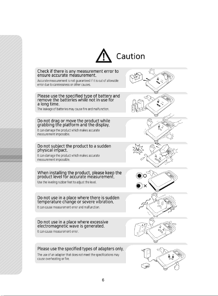
1. Safety Precaution
It is important to handle this product in the right way. If it is not used properly,
it may cause unexpected accidents resulting in personal injury or property
damage.
- In this manual, possible hazardous situations are informed in order to
prevent any accident. Such situations are displayed in different categories
(Warning, caution and notice).
(1) Unauthorized duplication of this manual in part or in whole is prohibited.
(2) The contents of this manual are subject to change without notice.
(3) If there is any incorrect or missing information in this manual, or if you
have any questions, please contact the place of purchase or
your nearest dealer.
(4) Please be informed that G-Tech does not accept any liability for loss or
claim for loss due to the operation of this device regardless of (2) and (3).
Page 5
5
Page 6
6
Page 7
7
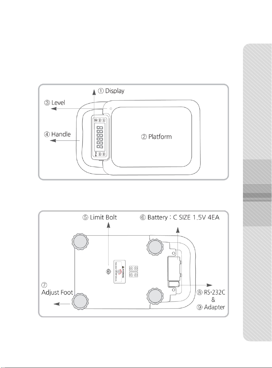
2. Name of Each Part and Product Size
2-1. Name of Each Part
① Display: Displaying the current weight on the platform
② Platform: Placing an object to be weighted
③ Level: Checking if the product is level
④ Handle: Convenient when moving the product
⑤ Limit Bolt: Load cell limit bolt ⑥ Battery: C SIZE 1.5V 4EA
⑦ Adjust Foot: Used to level the product
⑧ Communication Port: RS-232C type, ⑨ Adapter Jack
Page 8
8
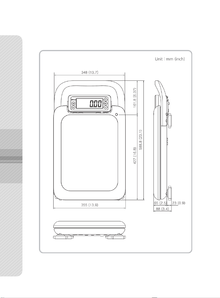
2-2. Product Size
Page 9
9
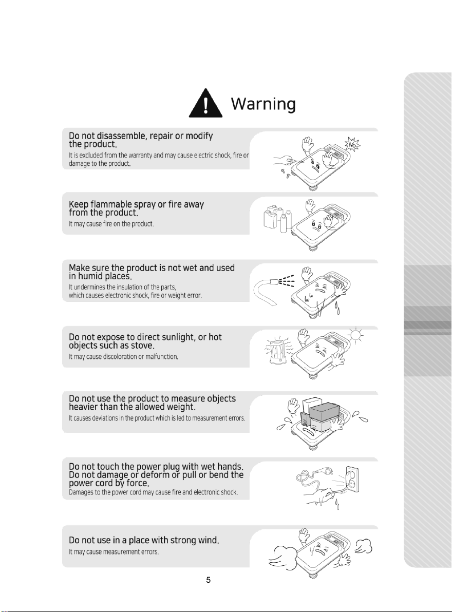
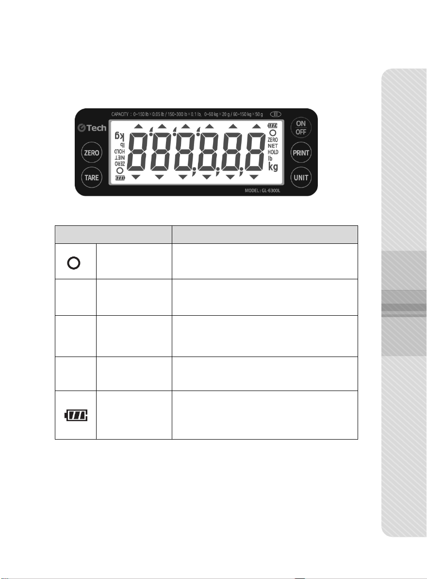
Symbol
Description
Stabilization
display lamp
It is turned on when the weight is stable.
ZERO
Zero
display lamp
It is turned on when the weight is “0”.
NET
Tare
display lamp
It is turned on while net
weight is displayed
( when tare function works ).
Ib / kg
Measurement unit
display lamp
It displays measurement unit.
Remaining battery
display lamp
It displays remaining battery.
(3 stages)
2-3. Display and Keys
Page 10
10
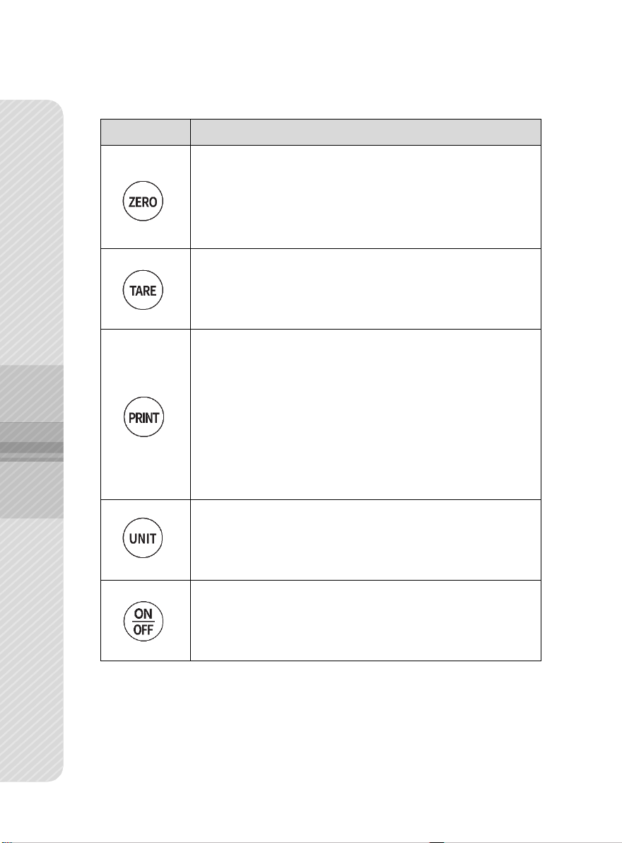
Key
Description
1) It sets the current weight “0” within a certain degree of
the maximum weight.
2) When the ‘Zero’ Key is long pressed, the direction of
LCD display is reversed.
1) It is used to set / release tare function.
2) When the Key is long pressed, you can adjust the upper
Limit / lower limit of value.
1) When the ‘PRINT’ Key is pressed after placing an object
on the platform, the current weight is transmitted
via communication port.
(Refer to Communication/Printer Output
Setting Mode on p.13)
2) When the ‘PRINT’ Key is pressed without an object on
the platform, the total amount of weight is printed out.
(when printer output is used)
1) When pressed short, measurement unit changes.
2) When pressed long, the upper limit/lower limit function
is turned ‘ON/OFF’.
1) It turns ‘ON/OFF’ the power.
Page 11

11
Type
Initial
Value
Setting
Value
Description
disable
It sets auto off time.
If the scale is stable for the preset time,
it is turned off automatically.
Notice: If the auto off time is set
10min., the product is automatically
turned off after 10 minutes.
3min
5min
●
10min
20min
30min
40min
50min
60min
3. User Setting Mode
3-1. How to Enter User Setting Mode
■
While pressing Key and Key, turn on to
show on the display and enter the User Setting Mode.
Change setting value using the following Keys.
■ : It changes setting mode or setting value.
■ : It confirms settings.
3-2. Description of User Setting
① Auto Off Time Setting
Page 12

12
Type
Initial
Value
Setting
Value
Description
darkest
It adjusts the brightness of the
backlight.
bright1
Bright2
Bright3
●
Bright4
Bright5
Bright6
Bright7
Type
Initial
Value
Setting
Value
Description
5s
It sets backlight auto off time.
If the scale is stable for the preset time,
the backlight is automatically turned off.
Notice: It is set 20s, the backlight is
turned off after 20 seconds.
10s
●
20s
30s
40s 50s 60s on
off
② Backlight Brightness Setting
③ Backlight Time Setting
Page 13
13
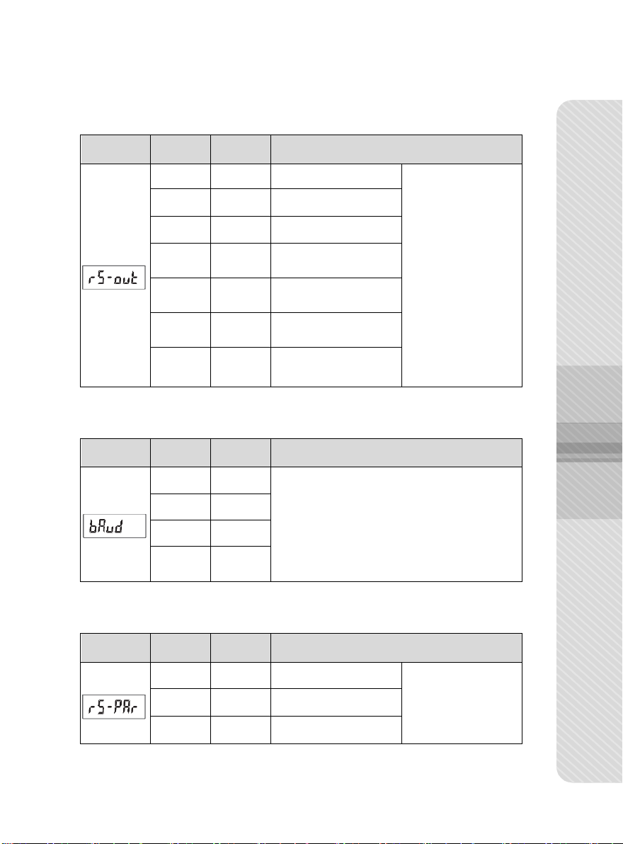
Type
Initial
Value
Setting
Value
Description
disable
Not used
It sets
Communication
& Printer Output
Mode.
●
stre-s
Serial (Stream)
comm-s
Serial (Command)
stab-s
Serial (when the
weight is stable)
keyz-s
Serial (when the PRINT
Key is pressed)
stab-p
Printer (when the weight
is stable)
keyz-p
Printer (when the
PRINT Key is pressed)
Type
Initial
Value
Setting
Value
Description
br-24
It sets baud rate.
Notice: It communicates in 9600bps
when setting br-96.
br-48
●
br-96
br-192
Type
Initial
Value
Setting
Value
Description
●
n81
8bits,Non Parity
It sets parity bit.
e81
8 bits, Even parity
o8
8 bits, Odd parity
④ Communication & Printer Output Setting
⑤ Baud rate Setting
⑥ Parity Bit Setting
Page 14

14
Type
Initial
Value
Setting
Value
Description
Form-1
It sets printer format.
Refer to the following format.
(This form is printed when "rs-out" is set stab-p or
keys-p.)
Form-2
Form-1 (Printer Format) Form-2 (Printer Format)
When the ‘PRINT’ Key is pressed without an object on the platform,
the total amount of weight is printed out. (when printer output is used)
Form-3
It sets RS-232C Communication 18 byte Data Format.
(Refer to 5-3. Data Format 1)
This form is transmitted when “rs-out” is set stre-s,
comm-s, stab-s or keys-s
●
Form-4
It sets RS-232C Communication 22 byte Data Format.
(Refer to 5-3. Data Format 2)
This form is transmitted when “rs-out” is set stre-s,
comm-s, stab-s or keys-s
Form-3 (Data format1 : 18byte)
Form-4 (Data format2 : 22byte)
⑦ Print Format Setting
Page 15

15
Type
Initial
Value
Setting
Value
Description
Slow
It sets display speed.
●
Medium
Fast
Type
Initial
Value
Setting
Value
Description
disable
It disables buzzer sound.
It sets buzzer
motion.
●
enable
It enables buzzer sound.
Type
Initial
Value
Setting
Value
Description
●
Net,
gross
Zero lamp is
displayed when
gross weight/net
weight is zero.
It sets zero lamp
display.
gross
Zero lamp is
displayed when
gross weight is
zero.
⑧ Display Speed Setting
⑨ Buzzer Motion Setting
⑩ Zero Lamp Display Setting
Page 16

16
Type
Initial
Value
Setting
Value
Description
off
It turns off
Limit function.
It sets conditions
for the Limit
function.
●
i-side
Lower limit ≤ current
weight ≤ upper limit
o-side
Current weight < lower
limit or current weight >
upper limit
lo
Current weight < lower limit
hi
Current weight >
upper limit
Type
Initial
Value
Setting
Value
Description
off
It turns off buzzer
sound.
It sets the buzzer
sound interval
while limit function
is on.
1 t
1 time per second
●
2 t
2 times per second
Type
Initial
Value
Setting
Value
Description
●
lit-us
It turns on Limit
function whether the
weight is stable or not.
It sets Limit function
depending on
stable/unstable
state. lit-st
It turns on Limit function
only the weight is stable.
Type
Initial
Value
Setting
Value
Description
●
-
Press ‘PRINT’ Key to save change values.
⑪ Limit Function Setting
⑫ Buzzer Sound of Limit Function
⑬ Limit Function Setting
⑭ Saving Settings
Page 17

17
Place an object on the
Platform.
when the display shows the
stabilization lamp (○).
Check the weight and
remove the object.
4. Mesaurement Mode and Functions
4-1. General Measurement
■ Turn on the power using the Key to initiate the product,
and wait until the weight value is stabilized.
■ When the weight on the scale is zero, “
■
While tare function is on, “
■ When the weight of an object is stabilized, “○”, which is stabilization
display lamp is turned on.
■ If the display does not show zero when there is no object on the
platform, adjust the zero point by pressing Key.
NET
4-2. Tare Function
ZERO
” lamp is turned on.
”, which is tare display lamp, is turned on.
■ In order to measure an object in a tare, use Key.
■ Place the tare on the platform, press Key to display “
■ Put an object in the tare to measure only the weight of the object.
■ In order to stop using the function, remove the tare and the object from
NET
”
lamp with the weight at “0.00”.
the platform, and press Key again. When the tare function is
released, the “NET” lamp will disappear.
Page 18

18
Place the tare on the
platform.
Press
TARE
Key.
Put the object in the tare to
measure only the weight of
the object.
In order to stop using the
function, remove the tare.
Press
TARE
Key again
to go back to 0 status.
4-3. Limit Function
■ Press Key for more than 3 seconds in Measuring Mode to
initiate limit function.
■ While limit function is on, buzzer sounds according to upper
Limit / lower limit conditions.
■ Limit Function Setting
Follow the process (p.11. 3-1. How to Enter User Setting Mode) and
set the limit function in ⑪ Limit Function Setting Mode.
■ In order to set lower/upper value, press Key for more than
3 seconds while the current weight is “0”.
Page 19

19
Keys
Description
Add 1 in the flickering digit
Move the flickering digit to the left
Save the settings
Exit without saving the settings
Keys to Change Settings
4-4. Weight Display Reverse Function
■ Press Key for more than 3 seconds while “0.00” is shown
on the display to switch the display in both the normal and reverse ways.
4-5. Unit Change Function
■ Press Key to change measurement unit.
( kg -> lb or lb -> kg )
■ Default unit is lb.
Page 20

20
Setting
Value
Description
disable
It disables communication output.
stre-s
It continuously transmit the value currently displayed on
the display.
comm-s
The scale is controlled by the commands transmitted
from a PC.
stab-s
When the certain amount of weight is stable, it
transmit the value currently displayed on the display
one time.
keyz-s
After the weight is stabilized after placing an object on the
platform, press “
ZERO
” Key to transmit the value just one
time.
4-6. Communication Function
How to Set Communication Function
■
Follow the process in “p.11, 3-1. How to Enter User Setting Mode” and
3-2. Description of User Setting “④ Communication & Printer Output Setting”,
“⑤ Baud Rate Setting”, “⑥ Parity Bit Setting” and “⑦ Print Format Setting.”
■ It transmits a measured value in RS-232C communication.
Initial display :
Page 21

21
Setting
Value
Description
stab-p
When the weight increases from 0 and stabilizes, it prints
out the value currently displayed on the display one time. In
order to print out the aggregate value, remove the object
from the platform and press “
PRINT
” Key.
keyz-p
After the weight is stabilized after placing an object on the
platform, press “
PRINT
” Key to print out the value on the
display one time. In order to print out the aggregate value,
remove the object from the platform and press “
PRINT
” Key.
4-7. Print Function
How to Set Print Function
■ Follow the process in “p.11, 3-1. How to Enter User Settings
Mode” and
Settings”, “⑤ Baud Rate Setting”, “⑥ Parity Bit Setting” and
“⑦ Print Format Setting”.
■ It prints out a measured weight using a printer.
■ How to Set print method.
Initial display :
3-2. Description of User Setting
“④ Communication/Printer Output
■ How to Set Printer Output Format
Set after entering
.
Page 22
22
RJ 11 Port
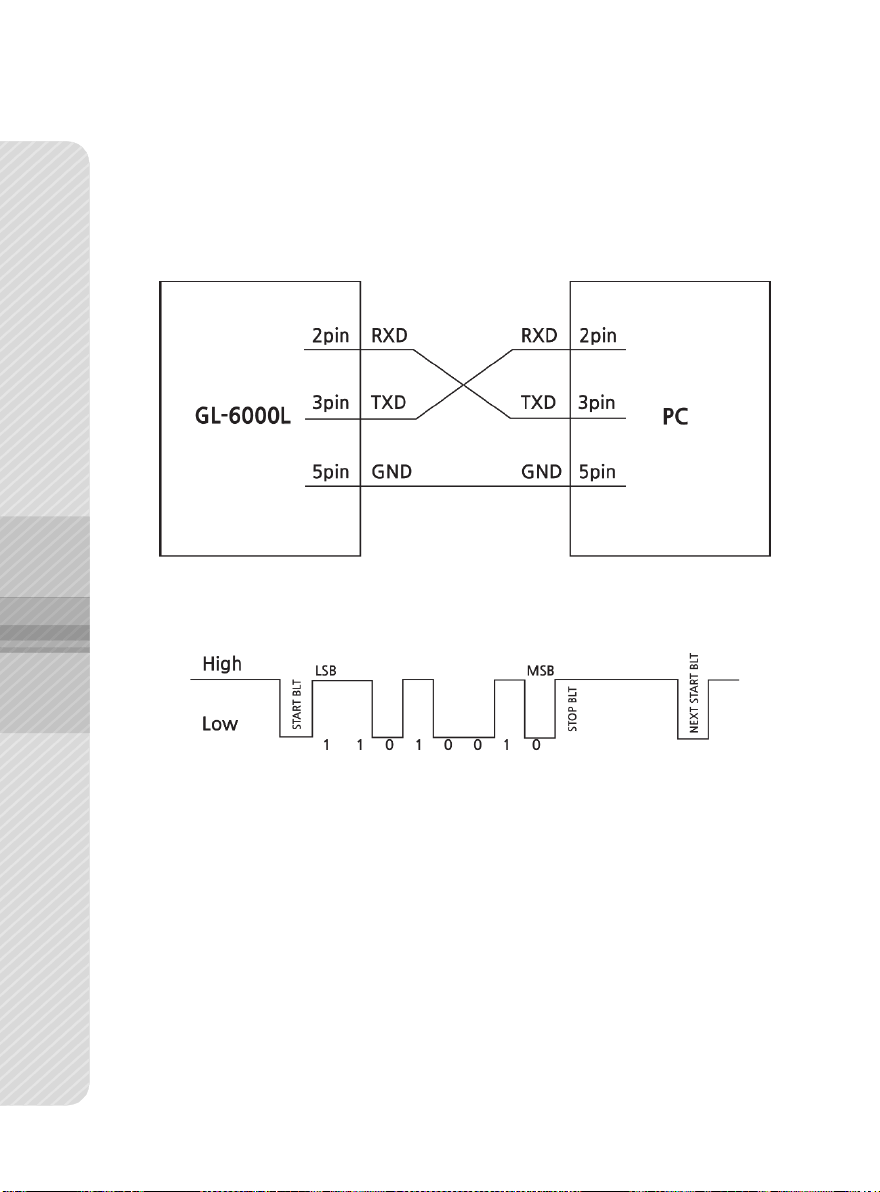
5. Communication Interface (RS-232C)
5-1. RS-232C Pin assignment and Connection
5-2. Signal Format
Page 23

23
5-3. Data Format
1) Data Format 1 (18 BYTE)
■ Header 1(2 BYTE)
“US” : Unstable Display
“ST”: Stable Display
“OL”: OVER LOAD
■ Header 2(2BYTE)
“GS” : Gross Weigh
“NT” : Net Weight
■ DATA [ 8 Byte ]
2B(H) : “ + ” PLUS
2D(H) : “ - ” MINUS
20(H) : “ ” SPACE
2E(H) : “ . ” DECIMAL POINT
■ Unit
“ kg”
“ lb”
Page 24
24
Bit 7 1 Bit 6
Stable
Bit 5 0 Bit 4
Hold
Bit 3
Printer
Bit 2
Gross
Weight
Bit 1
Tare
Bit 0
Zero
Point
Command
PC -> SCALE
SCALE -> PC
current weight
transmission
ASCII
R 𝐶𝑅 𝐿𝐹
ST, GS, + 0020.00 kg
HEX
52 0D 0A
53 54 2C 47 53 2C 2B 30 30
32 2E 30 30 6B 67 0D 0A
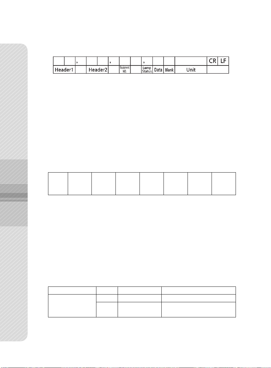
2) Data Format 2 (22 BYTE)
■ Header 1(2 BYTE)
“US” : Unstable Display
“ST” : Stable Display
“OL” : OVER LOAD
■ Header 2(2BYTE)
“GS” : Gross Weight
“NT” : Net Weight
■ Equipment No. : 0 x 0
■ Lamp status
■ Data (8 BYTE)
When the weight data including a decimal, for example, 13.5 kg,
8 bytes of ASCII code corresponding to
■ Blank (1BYTE)
■ Unit
“ kg”
“ lb”
“000013.5” are sent.
3) Command Format
Page 25
25
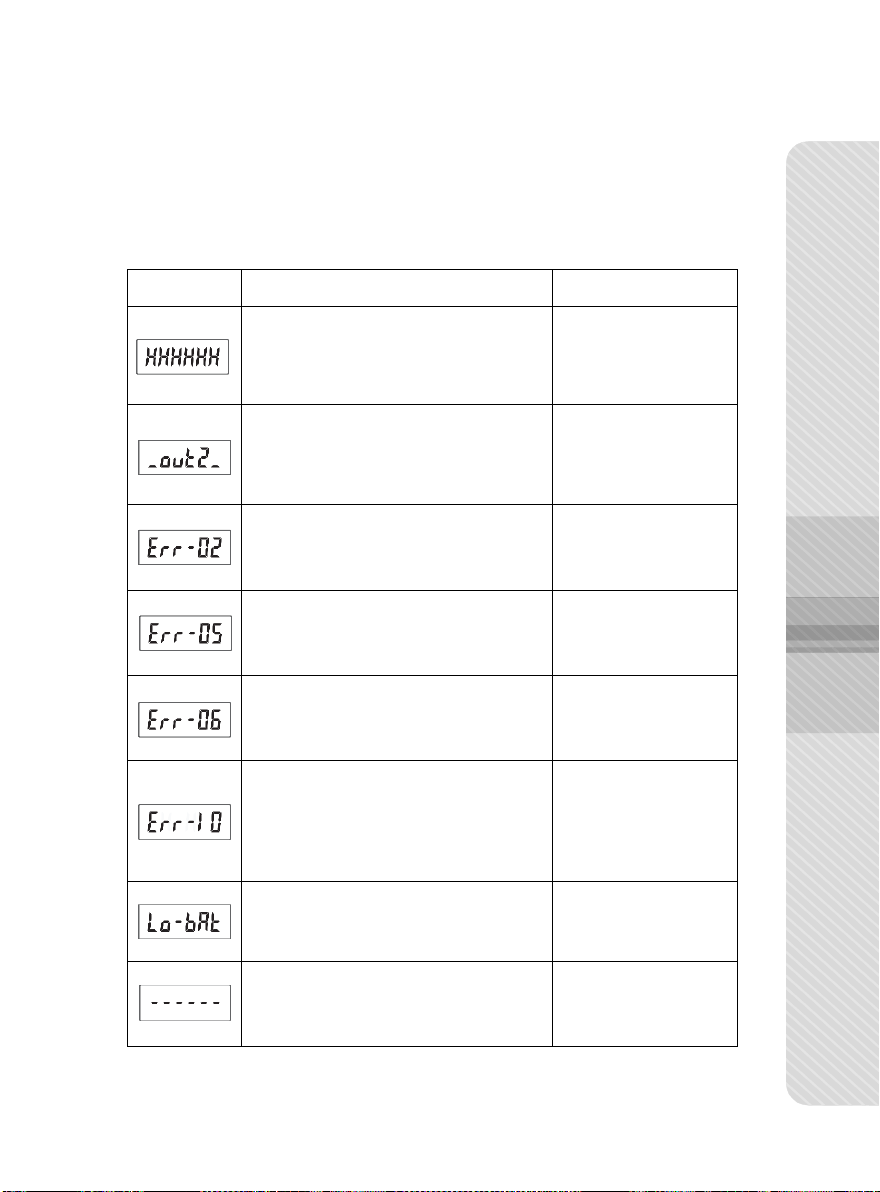
Message
Cause
Solution
The object on the platform exceed the
capacity.
Remove the object on
the platform.
the object weight exceed 20% of
capacity when the power on.
Empty the platform
before turning on the
power.
There is a problem in load cell part.
Refer to the
service center.
ZERO or TARE Keys was pressed when
the scale is unstable.
Check stabilization
status when pressing
Keys.
The value of lower limit exceeds the
value of upper limit.
Make sure upper limit
is higher than lower
limit.
The upper/lower limit value does not
meet the minimum graduation unit.
Set the upper/lower
limit value to a
multiple of the
minimum graduation
unit.
The battery is exhausted.
Replace battery.
The current weight is below ZERO.
Press
ZERO
Key.
6. Error Messages & Trouble Shooting Guide
■ If there is a problem with the scale, it displays error message for each
problem to facilitate inspection and repair.
Page 26

26
MODEL
GL-6060L
GL-6150L
GL-6300L
GL-6500L
Dual Interval
Dual Interval
Dual Interval
Dual Interval
Capacity (lbs)
30/60 lbs
60/150 lbs
150/300 lbs
250/500 lbs
Graduation
0.01/0.02 lbs
0.02/0.05 lbs
0.05/0.1 lbs
0.1/0.2 lbs
External
Resolution
1/3000
1/3000
1/3000
1/2500
Internal
Resolution
1/60000
1/75000
1/60000
1/50000
MAX Tare
-29.99 lbs
-59.98 lbs
-149.95 lbs
-249.9 lbs
Capacity (kg)
15/30 kg
30/60 kg
60/150 kg
100/200 kg
Graduation
5/10 g
10/20 g
20/50 g
50/100 g
External
Resolution
1/3000
1/3000
1/3000
1/2000
Internal
Resolution
1/60000
1/60000
1/75000
1/40000
MAX Tare
-14.995 kg
-29.99 kg
-59.98 kg
-99.95 kg
Display
LCD 6 Digit
LCD
5.1 x 1.8 inch / 130 x 48 (mm) / Large LCD
LCD Symbol
ZERO, NET, ○ (stabilization lamp) lb, kg, BATTERY (3 stages)
Keys
ZERO, TARE, PRINT, UNIT, ON/OFF: 5 functions in total
Sensor
Load Cell
Power
AC Adaptor: (SMPS)
Input: 100 V~240 V / 50~60 Hz, Output: DC 6 V / 0.5 A
Operation
Time
Alkaline: about 300 hours, Manganese: about 50 hours
Operating
Temperature
14 ℉ ~ 104 ℉ / -10 ℃ ~ +40 ℃
Interface
RS-232C
Platform Size
13.9(W) × 16.8(D) inch / 355(W) × 427(D) mm
Product Size
13.9(W) × 23.1(D) × 3.4(H) inch / 355(W) × 589(D) × 88(H) mm
Product
Weight
About : 15.3 lb / 6.95 kg
Feature
Setting Upper/Lower Limit and Buzzer Sound.
Options
DEP-50 Receipt Printer / Battery C-Type (LR14) 1.5V/4EA
7. Specification
※
The specifications of the product are subject to change without notice for the quality improvement.
Page 27

27
MEMO
Page 28

USA Branch
www.VisionTechShop.com
100 Temple Ave. Hackensack, NJ 07601
Tel : + 1-201-679-7793
Distributed by
Head Oce
Yonghyun Industrial Complex, 29, Sandan-ro 68beon-gil,
Uijeongbu-si, Gyeonggi-do, Korea 11781
www.gtech21.net
Tel : +82-31-852-4070 Fax : +82-31-852-4656
MADE IN KOREA
Ver.1.0
Aug. 2019
 Loading...