

Page 1

www.areameters.com
Ver 1.0
Page 1
USER MANUAL
Spreader Rate Control
Users Guide
Installation Manual
Page 2

Page 2
Copyright
All information contained in this user's guide is the
property of G-Tech NZ Ltd. All rights reserved. This
user's guide may not be , in whole or in part, be copied,
photocopied, reproduced, stored, or reduced to any
electronic medium or machine readable form, without
permisssion from G-Tech NZ Ltd.
IMPORTANT :
To obtain the highest Precision while Spreading:
– The Speed sensor must be mounted on a wheel that is not subject to slip or spin during the
Spreading.
– Wheel pulse distance and spreading width should corectly entered into to monitor.
– HOLD signal will flash when the spreader is not out putting material.
– Enter the correct setting for Material Density, Door Height, Rate and Spinner speed, to
allow the Field Mate to calculate the correct chain speed to suit the required spreading
rate.
– Calibrate the Spreader using the DUMP screen. Feed out one tonne of material and adjust
the FLOOR FACTOR as required to ensure the System will spread accurately.
Model ............................................................
Serial Number ............................................................
Date Purchased ............................................................
Place of Purchase.............................................................
Page 3

Introduction:
Warranty :
EMI Emmisssion Certification:
Pin outs 12 Pin plug:
Page 3
The FIELD MATE Spreader Rate controller and Area Meter has been developed to calculate land area, distance
travelled during spreading, while controling the speed of the floor chain to achieve a user defined spreading rate.
The meter will also record Spreading hours and timed stopped. While Spreading the meter can display the spreading rate
in hectare per hour and chain and spinner rpm as the desired spreading rate is controlled.
All measurements are metric.
A distance is measured via a magnetic wheel speed sensor. Shaft sensors are mounted on the chain and spinner motors.
Spreading on and off function is controlled by the in vehicle Fieldmate Run / hold switch.
To achieve the desired spreading rate the operator must enter the following:
- MATERIAL DENSITY.
- DOOR OPEN measurement.
- SPREADING RATE.
The FieldMate will compute the chain motor rpm to achieve the desired rate based on the 3 information sets entered
above.
ELECTRICAL SPECIFICATIONS
Pin/ number Colour Function
1 Black Earth
6 Yellow Speed
5 White Hold
3 Green Spinner RPM
2 Brown Chain RPM
7 Red
4 Blue Batt power to sensors and PWM solenoids.
8 Blue(3 core) Chain Left control. PWM switches to GND.
9 Brown(3 core) Chain Right or Spin control.
10 Yellow(3 core) Oil Temp
11 Red (2 core) Power to main oil valve control.
12 Red/Black(2 core) Earth to main oil valve.
1 Year Warranty on Field Mate Controller and sensors. All items under warranty claim must be returned to
GTECH New Zealand Ltd.
Please ensure you agree to the warranty conditions before proceeding to purchase this product,see the
warranty form at the end of this user guide.
Installation wiring and connectors are not covered.
This Computer has the following certifications:
Certification Country
C-Tick Z874 Class B New Zealand, Australia
FCC USA
Page 4

Specifications:
Features:
Page 4
Supply volts : 5 – 30 Volts
Max Field Mate Current : 25ma
Current Soleniod Current : 1 amp
Temperature : -5 to 55 degree/C
Input voltages : 0 to 30 Volts
Area : 999.99 hect
Distance : 999.99 km
Speed : 100 km/Hr
Wheel Size : 999.9 cm
Width : 9999.9 cm
Number of materials : 1
Number of Jobs : 1
-Large graphically displayed numbers, easy to see.
-3 button operation, for quick simple operation.
-Reset button is multi functional. It can:
A. Reset set the current job totals.
B. Shut down the alarm when the alarm is sounding
(eg: when low seed sensor has triggered).
C. Allows the meter to switch between auto
and manual mode when tramlining.
-Backlit display for night time working.
-Dust sealed.
-Mositure resistant.
-Strong Aluminium Case.
-Internal alarm buzzer.
-Bright light indicators.
-Easy fit velco mount. Or option window mount.
-Quick transfer from tractor to tractor.
-Reports all job information on screen.
-Automatic data Backup.
-Help Desk Phone number display.
-Data storage time with out power 20 years.
-All inputs high voltage protected.
Page 5
Start a Job
Note: This system is operated by either pressing and holding or quick pressing the 5 or 6or reset or power
buttons.
Page 5
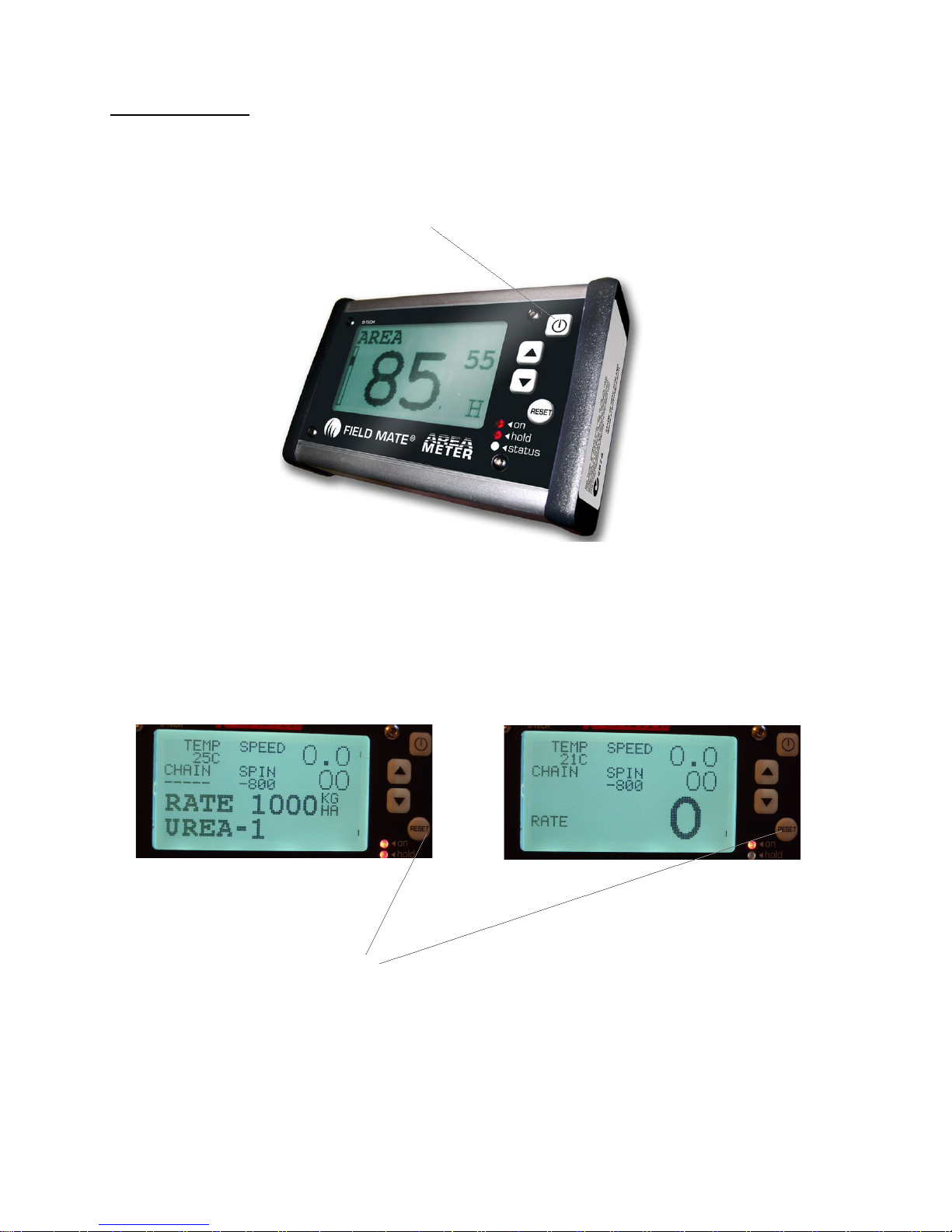
1. Turn On the system using the power button.
2. Turn on the oil valve using the control valve switch ( mounted in cab from the FieldMate wiring loom).
3. At power up one of the following screens are displayed. One screen is a HOLD screen, the other screen
is a RUN spreading.
4. Clear any information from a previous job by holding the REST switch
for 5 seconds. Only job spreading information is reset, all other user
setting are unaffected.
Page 6

Page 6
Page 7
Spreading control
Page 7
1. Use the HOLD / SPREAD Switch to start spreading. Spreading will only occur when this
switch is in the SPREAD Position and the Spreader speed is above 1 km/hour.
When in spreading mode the main screen will display the working rate and the state of the chain
motors and the spinner motor.
NOTE: THE OIL CONTROL VALVE SWITCH MUST BE ON TO ALLOW MOTORS TO
OPERATE.
Page 8
Information recorded
Page 8
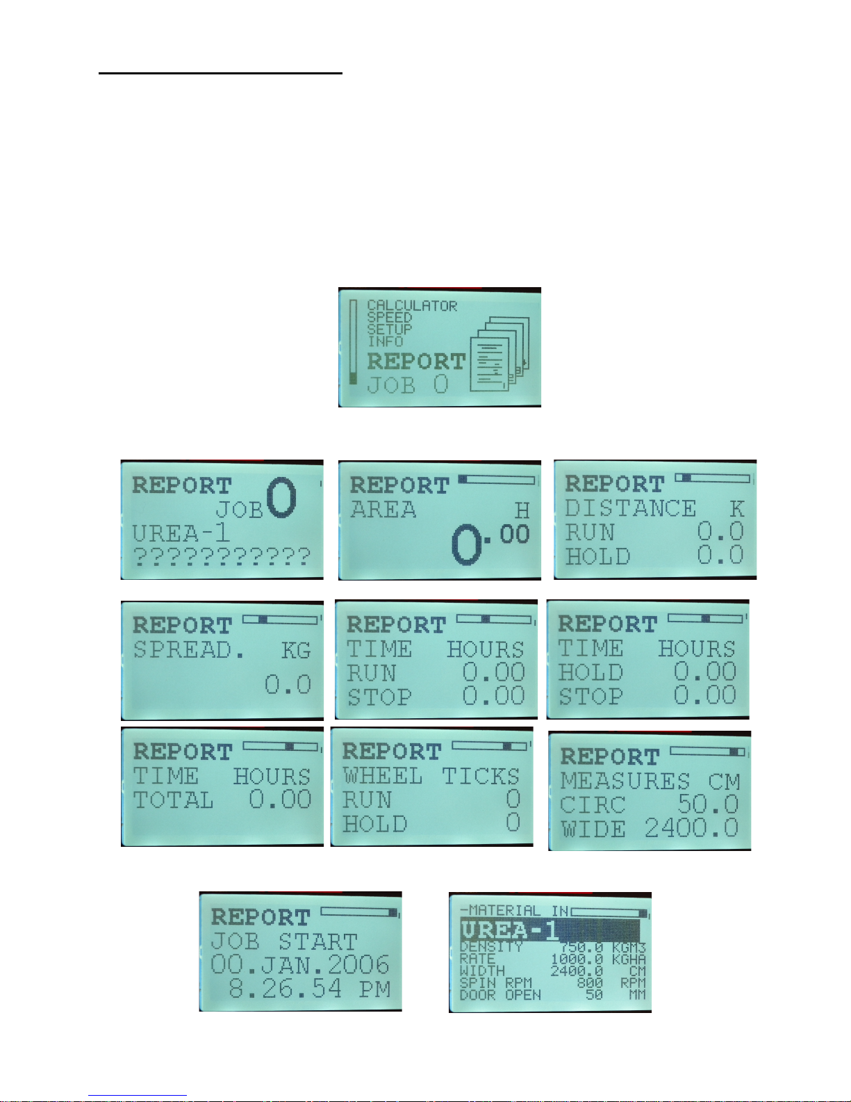
At any time during the spreading operation a report of the work done is reported in the REPORT Screen.
Using the arrow buttons at move to the REPORT screen, quick press the power button to enter the report
display screens. Spreading information reported:
- Area
- Distance spreading and not spreading
- Weight of material spread
- Time spreading, total time the job
- Wheel pulses for the current job
- Size of wheel size and width of machine
- Date and time the job was started
- Material details spread. Rate, Density etc.
Page 9

Dump Mode
Page 9
Dump mode is used to empty the spreader or to calibrate the spreader to output 1 tonne of material.
Calibrate the Spreader to output 1 tonne for material.
1. Goto DUMP mode.
2. Quick press the power button to enter DUMP mode.
3. Quick press the 5 button will put the spreader in to Dump Tonne mode. In this mode the TONNE label
will flash.
- Hold down the 5 or 6buttons to make the chain start.
- When the spreader has output 1 tonne the chains will stop.
Note 1: The weight and material output and based on the current material being spread. Accurate weight
calc is based on the exact door open measurement setting and the correct material density.
Note 2: The spreader must have a one tonne amount of material placed in the spreader if this calibration is
to be accurate. Then this 1 tonne is measure out to test spreader output calibration.
Note 3: If the Spreader stops at 1 tonne but with 100kg of material left in the spreader then this is
concidered a 10% over weighing. To fix reduce the Floor Factor by 10%.
Note 4: If the Spreader has output all the material when the weight is 900kg, then the spreader is
concidered to be 10% under weighing. To fix increase the Floor Factor by 10%.
Keep working with the FLOOR FACTOR number until 1 tonne of material is output from the spreader
when a 1 tonne bag is entered into the spreader.
Chain RPM during DUMP MODE. Hold the
5or 6buttons to achieve the desired RPM.
Speed of the Spinner in DUMP MODE. In a Twin floor system, this is under Mechanical
control. In Single floor mode the DUMP RPM is set in the SETUP Screens.
Weight out put by Spreader as calculated by the monitor, based
on internal settings and Material density and door opening.
The Chain RPM and rotations of the Chain motors are counted.
TONNE flashes when in dump tonne mode.
Page 10

Dump Mode
Page 10
Empty the Spreader using DUMP MODE.
1. Goto DUMP mode.
2. Quick press the power button to enter DUMP mode.
3. Quick press the 6 button will put the spreader in to EMPTY mode. In this mode the EMPTY label will
flash.
- Hold down the 5 or 6buttons to make the chain start.
- The Monitor will run the Chains until the user quick presses the power button. Or the chain motors are
stopped. Stop the chain motors by holding down the 5 or 6buttons.
Chain RPM during DUMP MODE. Hold the
5or 6buttons to achieve the desired RPM.
Speed of the Spinner in DUMP MODE. In a Twin floor system, this is under Mechanical
control. In Single floor mode the DUMP RPM is set in the SETUP Screens.
Weight out put by Spreader as calculated by the monitor, based
on internal settings and Material density and door opening.
The Chain RPM and rotations of the Chain motors are counted.
EMPTY flashes when in EMPTY mode.
Page 11

1: Mounting:
2: Connect Cables:
3: Configure the system using the SETUP option screens:
Page 11
Mount unit were it is easy to operate. Use the Ram mount fitting supplied to set the device in any
position.
Connect power the unit. Plug the 12 pin plug into the spreader 12 pin plug. These cables and sensors
should be factory connected.
INSTALLATION
Set display contrast.
Spreading width.
Speed sensor debounce.
Typical set 20%.
Set to Single or double floor
depending on spreader type.
This is distance the spreader
travels every time a wheel
pulse is received.
Date setup
Help desk phone number
Id of this unit
Setup time
Defines how often the Chain
valve PWM setting is
updated. Set to 2.
Page 12

Page 12
Defines how often the Spinner valve PWM
control is updated. Set to 2. Only used on
Single Floor system.
Displays the spinner speed for current job.
Defines Max Chain motor RPM.
Defines Max Spinner motor RPM.
Displays the distance in millimeters that
the door is open on the spreader for the
current job.
Displays the Spreading Rate for the
current job.
Displays the Product name for the current
job for the material being spread.
Number for spinner pulses that occur for
1 rev of the spinner motor.
Number for chain pulses that occur for 1
rev of the chain motor.
If Twin Floor system, here is where the
2nd chain pulse count is entered for 1 rev
of the chain motor.
Width of Spreader chain floor.
Chain gearbox ratio.
Number of speed pulses to occur before
the system knows it has travelled the
PULSE DISTANCE.
Spinner RPM when in DUMP mode.
Density of the material currently being
spread.
Page 13

Next screen is "SLOT OFFSET", this number is used by the
factory to set the correct amount of material driven from the
spreader. Relates to a single or double chain configured
machine.
For a Twin floor machine it is typically set to 2260.
Page 13
If programed rate not delivering correct
weight per hect this number can force the
rate to uder or over deliver material for
the set rate.
How often the Field Mate backs the system
up when not moving. Typically 1 min.
PWM setting of the spinner when it is just
about to start moving. Helps with fast
starting the motors.
PWM setting of the chain when it is just
about to start moving. Helps with fast
starting the motors.
Name of this Spreader.
Distance floor travels for 1 rev of the
chain motor. During calibration in dump
mode if the spreader is under or over
delivering material use this nnuber to
bring weight measurement into line
Learns Spinner motor verse PWM setting.
Adds in fast start up.
Learns Chain motor verse PWM setting.
Adds in fast start up.
RPM constant. Used to calc the extact
motor RPM.
Oil Alarm setting. If oil temp exceeds this
temperature an alert message is displayed.
RATE FACTOR
RATE FACTOR
FLOOR FACTOR
Page 14

Getting started.............
Page 14
Now that the area meter has been wired up, the area meter needs the following settings configured.
Step 1:
Turn unit on with power button.
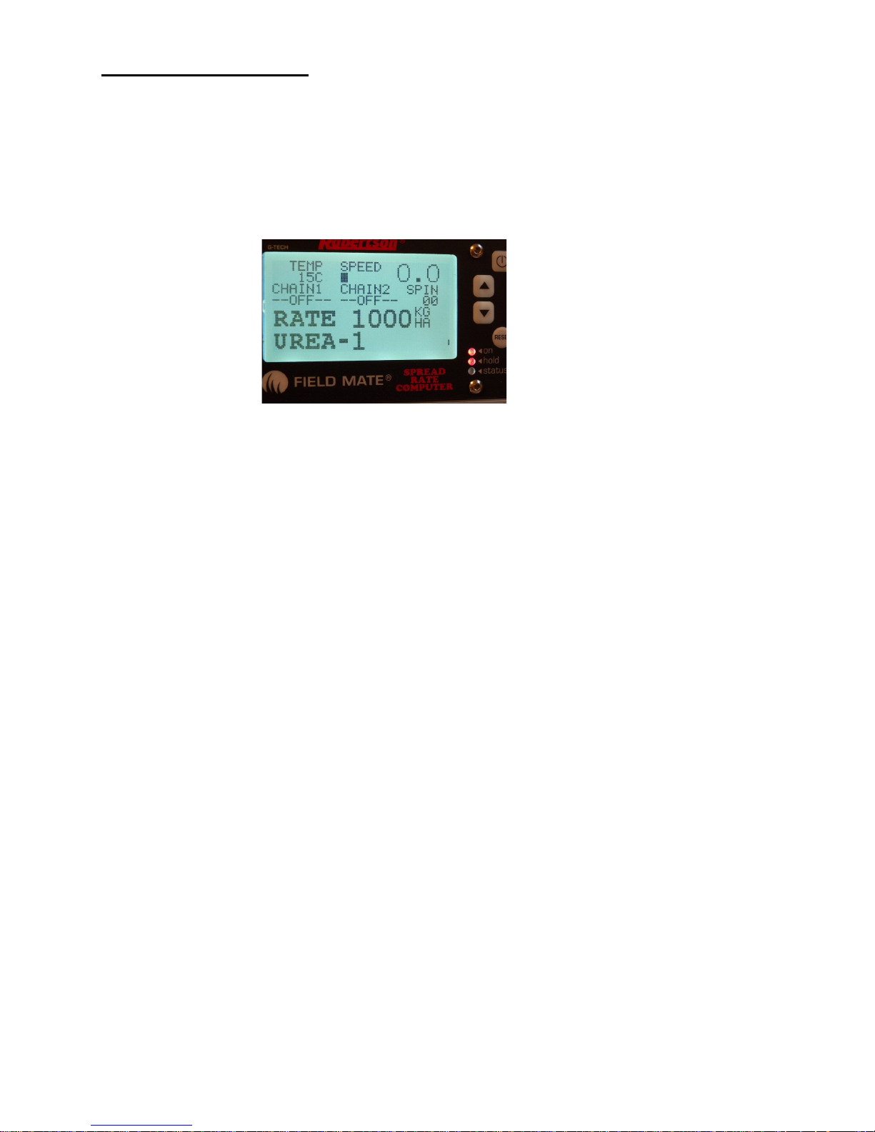
Step 2: Observe main screen
Single floor screen
Speed
The system is in hold, both chains motors
are off. In this HOLD mode the Rate and
material spread info are displayed.
Single Chain RPM and status of chain is
displayed here
Spinner RPM
Target RPM for Spinner. This Spinner is
PWM controlled
Oil temp
Page 15

Keyboard:
Connect Power:
Turning the Area Meter Off:
Turning the Area Meter ON:
Scroll Main Menu:
Page 15
The computer has 3 keyboard buttons, 5 or 6 and
power on/off.
The 4th button is the reset button that allows the user to
reset the current job totals
When unit is on hold down the "ON" button.
1: Unit will save all totals and display the company logo.
2: LCD will go blank, unit is off.
When unit is off hold down or quick press the "ON" button. The following information is
displayed on screen.
1: Job, Model.
2: Job number and description.
3: Displays system date and time..
Using the 5 or 6 buttons move up and down the menu options. The double size text is the selected menu.
Enter any of the selected menu items by a quick press of the "ON" button.
The following information is displayed on the Monitor Screen.
Page 16

Job Menu:
Operate Menu:
Page 16
1: In Main Menu scroll to OPERATE .
2: Quick Press “ON” to enter OPERATE Mode.
3: Use the 5 to display the following information types:
- AREA
- AREA sub (Reset this by holding down the 5or6 key)
- DISTANCE (Total distance travelled, combines the RUN and HOLD distances)
- WEIGHT of material spread for this job
- RATE, amount of hect per hour are being spread
- SPEED
- Spinner RPM
- Chain Left RPM
- Chain Right RPM
- All RPMs displayed on this screen
4a: Delete the displayed total by holding down5or6 keys for 6 seconds.
4b: In Optional screens holding down the 5or6for 6 sec turns the alarm on/off.
5: Use the 6 key if the"Run Hold Mode" is "Keys", to switch the Field Mate
into/out of Hold.
6: Quick press "ON to Exit to Main Menu.
Selecting a JOB:
This is done when a job is to be reset or restarted. A PRO has 16 jobs and there fore selecting
any of these jobs can be done by this method. A Job that has a "XX.XXX.XX" in the date location is an un allocated
job.
1: In the Main Menu scroll to JOB.
2: Quick Press “ON” to enter a JOB. Scroll to JOB using the 5or6 keys.
3: Hold 5or6 to select the job for adjusting.
4: Scroll to SELECT in the JOB SETUP screen Using 5or6. At SELECT hold 5or6 to select the job.
This job will be the current Job that work is logged to. Date and Time renewed . Job Totals and Job Name remain
untouched.
Reset a JOB:
1: In Main Menu scroll to JOB.
2:Quick Press “ON” to enter JOB. Scroll to JOB using the 5or6 keys.
3: Hold 5or6 to select the job for adjusting.
4:Scroll to RESET in the JOB SETUP screen Using 5or6.
5: At RESET hold 5or6 to reset the job. All Totals, Date, Time and Name for this job will be cleared.
Caution: Data cannot be recovered after this event.
Name a JOB:
1: In Main Menu scroll to JOB.
2: Quick Press “ON” to enter JOB. Scroll to JOB using the 5or6 keys.
3: Hold 5or6 to select the job for adjusting.
4: Scroll to NAME in the JOB SETUP screen Using 5or6. At NAME hold
5or6 to name the job.
5: At the NAME job screen 5 will change letter, 6 will goto the next letter
space. A maximum of 11 letters can be entered.
6: Quick press “ON” to exit.
View a JOB:
1: In Main Menu scroll to JOB.
2: Quick Press “ON” to enter JOB. Scroll to JOB using the 5or6 keys.
3: Hold 5or6 to select the job for adjusting.
4: Scroll to VIEW in the JOB SETUP screen Using 5or6. At VIEW hold
5or6 to select the job. Report screen will be displayed.
5 : Use 5or6to scroll through the job report.
6: Quick press “ON” to exit. Viewing job does not unset the selected job.
7: When exiting to the Main Menu, the Job Report is set back to the Current Selected Job Number.
Page 17

Area Menu:
Distance Menu:
Speed Menu:
Page 17
1: In Main Menu scroll to AREA .
2: Quick Press “ON” to enter AREA Mode.
3: Use the 5 to display the following information types:
- AREA. Area amount for the current job.
- AREA SUB. Sub area total that can be reset any time.
- AREA Total. Area of all jobs done by the meter.
4: Use the 6 the key if the"Run Hold Mode" is Keys to switch the Field Mate into and out of Hold.
5: Quick press "ON to Exit to Main Menu.
1: In Main Menu scroll to DISTANCE .
2: Quick Press “ON” to enter DISTANCE Mode.
3: Use the 5 to display the following information types:
- DISTANCE. Distance travelled in RUN mode for the current job.
- DISTANCE SUB. Distance travelled in HOLD mode for the current job.
- DISTANCE TOTAL. Total distance travelled in HOLD and RUN mode for the current job.
4: Use the 6 key if the"Run Hold Mode" is "Keys", to switch the Field Mate
into and out of Hold.
5: Quick press "ON to Exit to Main Menu.
1: In Main Menu scroll to SPEED .
2: Quick Press “ON” to enter SPEED Mode.
3: Use the 5 key to display the following information types:
- RATE , Hect/Hr.
- Time in Run mode.
- Time in Hold mode.
- Total job time.
- Max speed.
- Average Speed.
- Oil Temp.
- Time.
- Date.
- Area of current job.
- Distance or current job.
- Working machine width.
- Large speed number displayed
4: Delete the displayed total by holding down5or6 keys for 6 seconds.
5: Use the 6 key if the"Run Hold Mode" is "Keys", to switch the Field Mate
into and out of Hold.
6: Quick press "ON to Exit to Main Menu.
Page 18

Setup Menu:
Page 18
1: In Main Menu scroll to SETUP .
2: Quick Press “ON” to enter SETUP Mode.
3: Use the 5or6 keys to toggle scroll through the various setup options.
4: When at the required Setup option, to enter the Option hold down 5or6
key to enter the Setup mode for the Option.
5: When in the Option use the 5or6 keys to adjust the options settings. EG:
Screen 1:
- CONTRAST. Allows display clarity to be set up.
- DEBOUNCE. Allows meter to monitor extremly slow coulter shaft typically set to 20% .
- RUN / HOLD. The meter will go into HOLD mode as define be the setting here. For a Spreader
there are 2 options, Single and twin floor.The operator will manually switch between
run and hold using the run/hold switches. When in run mode and moving the
computer will record are spread etc and control the chain motors accordingly.
Other RUN/ HOLD modes:
- ONE FLOOR. For single floor spreader.
- TWIN FLOOR. For twin floor spreader.
- DIST PULSE. Is the distance travelled by the spreader each time the speed sensor is triggered.
- WIDTH. Is the spreading width of the spreader. This number is used to work out area spread.
Screen 2:
- DATE. Set date here.
- SUPPORT. Enter a HELP DESK Phone number here of who to ring for Area Meter support.
- UNIT ID. Allows the unit to be named. Allows easy identification of a Meter.
- TIME Set time here
- CHAIN UPDATE. Sets the update rate for the PWM for the chain motor/s. Typically set to 2.
Screen 3:
- SPIN UPDATE. Sets the update rate for the PWM for the spinner motor. Typically set to 2. Only
with the Single floor is the spinner computer controlled
- JOB SPIN RPM. Speed of the spinner for the current job
- MAX CHAIN RPM. Max RPM for the chain motor
- MAX SPIN RPM. Max RPM for the spinner motor
- DOOR OPENING. Door open setting for the current job
Screen 4:
- SPREADER RATE. Spreader rate for the current job
- PRODUCT. Name of product for the current job
- SPINNER PULSE. Number of Spinner pulses for 1 rev of the Spinner motor
- CHAIN PULSE. Number of Chain pulses for 1 rev of the Chain motor
- CHAIN 2 PULSE Number of Chain pulses for 1 rev of the Chain motor (Note**)
Screen 5:
- FLOOR WIDTH. Width of the chain floor
- DENSITY. Density of the Material being spread
- BOX RATIO. Ration betwen the chain motor and the floor out put shaft
- SPEED PULSE. Number of speed pulses to count before the DIST PULSE distance is travelled
- DUMP SPIN In dump mode and Single floor this is the RPM of the Spinner
Screen 6:
- RATE FACTOR. If Over or under spreading compare to the set rate then this number with make the
spreader eeith incres the spreading amount or decrease the spreading amount.
If set to 1.000 no change to the set rate. If set to 1.0500 then the rate will be reduced
by 5%. If set to 0.950 then the rate is increased by 5%.
- AUTO SAVE. Time interval for the meter auto saving date when machine is not moving.
- SPIN STOPPED. PWM setting that has the spinner almost moving, this helps for soft stoping and
starting the spinner.
- CHAIN STOPPED. PWM setting that has the chain almost moving, helps for starting the chain/s.
- IMP NAME. Name for implement, as reported on the report
Screen 7:
- FLOOR FACTOR. Used to get the spreader outputing the correct weight in dump mode.
- LEARN SPIN. In single floor mode, this date is the last time the spinner motor was learn, this
learning process makes quick start for the spinner motor possible.
- LEARN CHAIN. This date is the last time the chain motor was learnt, this learning process makes
quick start for the chain motor possible.
- RPM CONSTANT. Number used to case calc the RPM for the motor. Typically 906.
- OIL ALARM. Temperature when the oil temp alarm will alert the user that the oil temp has reached
this level.
Screen 8:
- SLOT OFFSET. Used to offset the material door setting area. Due to the chain taking up part of the
output slot. Typically set to 2260
Page 19

Page 19
Setup Continued:
Info Menu:
1: In Main Menu scroll to INFO .
2: Quick Press “ON” to enter INFO Mode.
3: Use the 5or6 keys to toggle scroll through the various information screens.
4: Display a varity of information that may be useful to the user, or in some cases a valuable tool in
working out if the area meter doing that job you want it to do. There are also low level information
here that give insight into the correct operation of the computer system that makes this area meter
what it is. Information may prove to be a useful tool used during installation.
Screen 1: - Meter logo graphic
Screen 2: - Help desk info
Screen 3: - Distance travelled pulse detection timing and detection info screen.
Screen 4: - Meter model infomation.
- Firmware release info
- Hours that the meter has been running, powered up and calculating area.
- LCD contrast setting and backlight voltage on/off control state.
Screen 5: - Temperature of oil.
- Voltage level applied to the meter.
- Serial number.
- RUN HOLD voltage level. Reflects run hold state in twin floor confiuration.
Screen 6: - Software error detection. Should be all 0.
- PWR is the number of power ups that the meter has had.
- BOD may get counts, this is a low power detection.
Screen 7: - Auto save count down timer.
- Average speed.
- Time and distance calculator numbers.
Screen 8: - Real Time Clock/Calendar timer information
- Run Hold state number.
- Area calculator numbers.
- Time number.
Screen 9: - Real rate verse filtered rate.
- Area calculator numbers
Screen 10: - All motors rpm monitor screen
Screen 11: - States that options are on
Screen 12: - Calcs to work out rpm of chain motor
Screen 13: - Spinner rpm with target rpm and pwm settings
Screen 14: - Chain Left with target rpm and pwm settings
Screen 15: - Chain Right with target rpm and pwm settings
Screen 16: - Weight calcs
Screen 17: - Spinner rpm calcs.
Screen 18: - Chain Left rpm calcs.
Screen 19: - Chain Right rpm calcs.
Screen 20: - Variable used to calc the volume of the output slot of the spreader
Screen 21: - Extended variables to calc the weight out of the spreader and computed weight output by the
spreader for t rev of the chain motor
Screen 22: - Rate and how it is effected by the rate correction number
Page 20

Report Menu:
Clearing the Meter.
*Hold the Reset key down for 5 seconds to delete the current job information.
Page 20
Reset all Jobs:
1: Turn FIELD MATE tm Off.
2: Hold down the 6 key, "RESET ALL JOBS" is displayed and a scroll bar
counts across at the bottom of the screen.
3: Repeat step 2, 3 times to reset all the job totals.
4: The reset is complete when "RESET ALL JOBS DONE" is displayed.
1: In Main Menu scroll to REPORT .
2: Quick Press “ON” to enter REPORT Mode.
3: Use the 5or6 keys to toggle scroll through the various Report screens eg:
Screen 1: - Displays job number + name.
Screen 2: - Area worked in RUN mode.
Screen 3: - Distance travelled in RUN mode.
- Distance travelled in HOLD mode.
Screen 4: - Weight output.
Screen 5: - Time moving in RUN mode.
- Time stopped in RUN mode.
Screen 6: - Time moving in HOLD mode.
- Time stopped in HOLD mode.
Screen 7: - Total time spent on this job.
Screen 8: - Wheel turns in RUN mode.
- Wheel turns in HOLD mode.
Screen 8: - Measurements used for this job. Wheel size and width.
Screen 9: - JOB start time and date.
Screen 10: - Details of the material spread
4: While at the first report screen hold down the 6 key to view the report of the next job. (PRO meters only)
5: While at the first report screen hold down the 5 key to view the report of ALL jobs total. (PRO meters only)
6: Quick press "ON to Exit to Main Menu.
Page 21

Using the "FieldMate Reporter" software.
Page 21
Use this application to down load Job information from any PRO series Meter.
1: Connect the Meter to the down load cable attached to the office PC.
A : The Meter should connect to a DB15 cable
B : The DB15 cable connects to a USB serial converter with DB15 adaptor fitted.
C : The USB coverter is connected to the USB port of the office PC.
2: Start the FieldMate Reporter software by double clicking on the icon.
Note: If the reporter software is not installed, install from the factory supplied CD, or
down load the install files from www.areameters.com .
3: Ensure that the FM-DRILL PRO is turned on. This software will automactically detect that a PRO version
FieldMate area meter is connected. When this occurs the "DOWN LOAD READY" button is displayed.
4: With the FM-DRILL PRO connected to the computer. Press the "DOWNLOAD READY" button. The
data is instantly returned fromthe meter. At this point the "PRINT" and "SAVE" buttons will be enabled.
Note 1 : If a " DOWNLOAD READY " button is not observed, check that the comm port that is
connected to the FM-DRILL PRO is the correct port. If required select the correct comm
port using the "Connect Port" button.
5: Once the job info is down loaded, click on the job buttons to display the work done for each job.
6: To save the job info to a file press the "File Save" button.
7: Any or all job data can be printed at any time, using the "Print" button..
8: The Field Mate Reporter Application will only operate with the PRO.
The FieldMate Area Meter can record all your machine based agricultural activites,
making invoicing and job tracking a breeze.
Page 22

Example of report
MASTER JOB# = SPREADER 34 - 000001,
CLIENT NAME = ,
IMPLEMENT NAME = AUTO SPREAD,
DATE = 00.JAN.2006,
TIME = 8.26.54PM,
FIRMWARE VERSION = SPREADER TWIN 43,
TWIN FLOOR,
,
AREA = 00007.3657 Hectares ,
WEIGHT SPREAD = 000006102 KG ,
,
RUN DIST = 00003.4348 KM,
HOLD DIST = 00000.4473 KM,
,
TIME_RUN_MOVING = 0.33 Hour.Min,
TIME_RUN_STOPPED = 0.58 Hour.Min,
TIME_HOLD_MOVING = 0.03 Hour.Min,
TIME_HOLD_STOPPED = 1.06 Hour.Min,
TIME_TOTAL = 2.41 Hour.Min,
,
TICK_RUN = 004334,
TICK_HOLD = 000568,
WHEEL SIZE = 000500 MM,
MACHINE WIDTH = 024000 MM,
,
MATERIAL SPREADER ID = 000000,
Material #000001,
Name = UREA-1 ,
DENSITY = 00750 KG/M3,
RATE = 01000 KG/HA,
WIDTH = 02400 CM,
SPINNER RPM = 000000 RPM,
DOOR OPENING = 000100 MM,
END
Page 22
Page 23

Example of configuration
Page 23
MATERIAL CURRENTLY LOADED TO
SPREAD:000000,
Job #000007,
Material #000001,
Name = UREA-1 ,
DENSITY = 00750 KG/M3,
RATE = 01000 KG/HA,
WIDTH = 02400 CM,
SPINNER RPM = 000000 RPM,
DOOR OPENING = 000100 MM,
,
,
GENERAL SYSTEM DATA:,
Run Hold mode = TWIN FLOOR ,
Spreader Setup as Twin Floor,
Firmware Version = SPREADER TWIN 43,
wheel_circumference = 000830,
speedo_debounce_limit = 000020,
run_hold_sensor = 000004,
drill_width = 02400,
backlight_mode = 000001,
unit_type = 000001,
lcd_contrast = 000023,
PWM_Enabled = 000000,
motor_1_connected = 000000,
motor_2_connected = 000000,
drill_wheel_pulse_rev = 000003,
Reference_speed = 000004,
reference_rpm = 000005,
machine_model = 000050,
speed_hours_moving = 000337,
speed_hours_run_stopped = 000093,
speed_hours_hold_moving = 000300,
speed_hours_stopped = 000704,
Support number = 0211535759 ,
,
,
SPREADER SETUP VARIABLES:,
spreader_material_density = 00750,
spreader_rate = 01000,
drill_width = 02400,
shaft_1_rpm_limit = 000000,
spreader_door_opening = 000100,
spreader_floor_width = 000727,
spreader_gearbox_ratio = 000122,
speedo_pulse_count_per_distance = 000001,
spreader_spinner_rpm_dump_mode = 000123,
shaft_1_rev_pulse = 000012,
shaft_2_rev_pulse = 000010,
spinner_stopped_pwm = 010000,
chain_stopped_pwm = 009386,
shaft_update_time = 000001,
spinner_motor_pwm_update_rate = 000002,
chain_motor_pwm_update_rate = 000002,
max chain motor rpm = 000250,
max spinner motor rpm = 001200,
,
,
Variables to calibrate spreader,
rate correction = 010700,
out put slot area offset = 002260,
floor_factor = 023609,
,
,
PRODUCT SETTINGS:,
,
Material #000001,
Name = UREA-1 ,
DENSITY = 00750 KG/M3,
RATE = 01000 KG/HA,
WIDTH = 02400 CM,
SPINNER RPM = 000000 RPM,
DOOR OPENING = 000100 MM,
,
Material #000002,
Name = SUPER-1 ,
DENSITY = 011200 KG/M3,
RATE = 002750 KG/HA,
WIDTH = 024000 CM,
SPINNER RPM = 000850 RPM,
DOOR OPENING = 000060 MM,
,
Material #000003,
Name = LIME-1 ,
DENSITY = 00750 KG/M3,
RATE = 01770 KG/HA,
WIDTH = 01200 CM,
SPINNER RPM = 000000 RPM,
DOOR OPENING = 000060 MM,
,
Material #000004,
Name = NAME?? ,
DENSITY = 007500 KG/M3,
RATE = 010000 KG/HA,
WIDTH = 012000 CM,
SPINNER RPM = 000500 RPM,
DOOR OPENING = 000050 MM,
,
Material #000005,
Name = NAME?? ,
DENSITY = 007500 KG/M3,
RATE = 010000 KG/HA,
WIDTH = 012000 CM,
SPINNER RPM = 000500 RPM,
DOOR OPENING = 000050 MM,
,
Material #000006,
Name = NAME?? ,
DENSITY = 007500 KG/M3,
RATE = 010000 KG/HA,
WIDTH = 012000 CM,
SPINNER RPM = 000500 RPM,
DOOR OPENING = 000050 MM,
,
Material #000007,
Name = NAME?? ,
DENSITY = 007500 KG/M3,
RATE = 010000 KG/HA,
WIDTH = 012000 CM,
SPINNER RPM = 000500 RPM,
DOOR OPENING = 000050 MM,
,
Material #000008,
Name = NAME?? ,
DENSITY = 007500 KG/M3,
RATE = 010000 KG/HA,
WIDTH = 012000 CM,
SPINNER RPM = 000500 RPM,
DOOR OPENING = 000050 MM,
,
Material #000009,
Name = NAME?? ,
DENSITY = 007500 KG/M3,
RATE = 010000 KG/HA,
WIDTH = 012000 CM,
SPINNER RPM = 000500 RPM,
DOOR OPENING = 000050 MM,
,
Material #000010,
Name = NAME?? ,
DENSITY = 007500 KG/M3,
RATE = 010000 KG/HA,
WIDTH = 012000 CM,
SPINNER RPM = 000500 RPM,
DOOR OPENING = 000050 MM,
,
Material #000011,
Name = NAME?? ,
DENSITY = 007500 KG/M3,
RATE = 010000 KG/HA,
WIDTH = 012000 CM,
SPINNER RPM = 000500 RPM,
DOOR OPENING = 000050 MM,
,
Material #000012,
Name = NAME?? ,
DENSITY = 007500 KG/M3,
RATE = 010000 KG/HA,
WIDTH = 012000 CM,
SPINNER RPM = 000500 RPM,
DOOR OPENING = 000050 MM,
Material #000013,
Name = NAME?? ,
DENSITY = 007500 KG/M3,
RATE = 010000 KG/HA,
WIDTH = 012000 CM,
SPINNER RPM = 000500 RPM,
DOOR OPENING = 000050 MM,
,
Material #000014,
Name = NAME?? ,
DENSITY = 007500 KG/M3,
RATE = 010000 KG/HA,
WIDTH = 012000 CM,
SPINNER RPM = 000500 RPM,
DOOR OPENING = 000050 MM,
,
Material #000015,
Name = NAME?? ,
DENSITY = 007500 KG/M3,
RATE = 010000 KG/HA,
WIDTH = 012000 CM,
SPINNER RPM = 000500 RPM,
DOOR OPENING = 000050 MM,
,
Material #000016,
Name = NAME?? ,
DENSITY = 007500 KG/M3,
RATE = 010000 KG/HA,
WIDTH = 012000 CM,
SPINNER RPM = 000500 RPM,
DOOR OPENING = 000050 MM,
,
Material #000017,
Name = NAME?? ,
DENSITY = 007500 KG/M3,
RATE = 010000 KG/HA,
WIDTH = 012000 CM,
SPINNER RPM = 000500 RPM,
DOOR OPENING = 000050 MM,
Material #000018,
Name = NAME?? ,
DENSITY = 007500 KG/M3,
RATE = 010000 KG/HA,
WIDTH = 012000 CM,
SPINNER RPM = 000500 RPM,
DOOR OPENING = 000050 MM,
,
Material #000019,
Name = NAME?? ,
DENSITY = 007500 KG/M3,
RATE = 010000 KG/HA,
WIDTH = 012000 CM,
SPINNER RPM = 000500 RPM,
DOOR OPENING = 000050 MM,
,
Material #000020,
Name = NAME?? ,
DENSITY = 007500 KG/M3,
RATE = 010000 KG/HA,
WIDTH = 012000 CM,
SPINNER RPM = 000500 RPM,
DOOR OPENING = 000050 MM,
,
,
SPINNER MOTOR RPM-PWM SETTINGS:,
RPM SETTINGS:,
SPINNER RPM MAX = 001200,
SPINNER RPM AT 5% OF MAX = 000000,
SPINNER RPM AT 10% OF MAX = 000000,
SPINNER RPM AT 15% OF MAX = 000000,
SPINNER RPM AT 20% OF MAX = 000000,
SPINNER RPM AT 25% OF MAX = 000000,
SPINNER RPM AT 30% OF MAX = 000000,
SPINNER RPM AT 35% OF MAX = 000000,
SPINNER RPM AT 40% OF MAX = 000000,
SPINNER RPM AT 45% OF MAX = 000000,
SPINNER RPM AT 50% OF MAX = 000000,
SPINNER RPM AT 55% OF MAX = 000000,
SPINNER RPM AT 60% OF MAX = 000000,
SPINNER RPM AT 65% OF MAX = 000000,
SPINNER RPM AT 70% OF MAX = 000000,
SPINNER RPM AT 75% OF MAX = 000000,
SPINNER RPM AT 80% OF MAX = 000000,
SPINNER RPM AT 85% OF MAX = 000000,
SPINNER RPM AT 90% OF MAX = 000000,
SPINNER RPM AT 95% OF MAX = 000000,
SPINNER RPM AT 100% OF MAX = 000000,
PWM SETTINGS:,
SPINNER PWM SET FOR 0% of MAX SPINNER
RPM = 010000,
SPINNER PWM SET FOR 5% of MAX SPINNER
RPM = 000000,
SPINNER PWM SET FOR 10% of MAX SPINNER
RPM = 000000,
SPINNER PWM SET FOR 15% of MAX SPINNER
RPM = 000000,
SPINNER PWM SET FOR 20% of MAX SPINNER
RPM = 000000,
SPINNER PWM SET FOR 25% of MAX SPINNER
RPM = 000000,
SPINNER PWM SET FOR 30% of MAX SPINNER
RPM = 000000,
SPINNER PWM SET FOR 35% of MAX SPINNER
RPM = 000000,
SPINNER PWM SET FOR 40% of MAX SPINNER
RPM = 000000,
SPINNER PWM SET FOR 45% of MAX SPINNER
RPM = 000000,
SPINNER PWM SET FOR 50% of MAX SPINNER
RPM = 000000,
SPINNER PWM SET FOR 55% of MAX SPINNER
RPM = 000000,
SPINNER PWM SET FOR 60% of MAX SPINNER
RPM = 000000,
SPINNER PWM SET FOR 65% of MAX SPINNER
RPM = 000000,
SPINNER PWM SET FOR 70% of MAX SPINNER
RPM = 000000,
SPINNER PWM SET FOR 75% of MAX SPINNER
RPM = 000000,
SPINNER PWM SET FOR 80% of MAX SPINNER
RPM = 000000,
SPINNER PWM SET FOR 85% of MAX SPINNER
RPM = 000000,
SPINNER PWM SET FOR 90% of MAX SPINNER
RPM = 000000,
SPINNER PWM SET FOR 95% of MAX SPINNER
RPM = 000000,
SPINNER PWM SET FOR 100% of MAX SPINNER
RPM = 000000,
,
,
CHAIN MOTOR RPM-PWM SETTINGS:,
RPM SETTINGS:,
CHAIN RPM MAX = 000250,
CHAIN RPM AT 5% OF MAX = 000012,
CHAIN RPM AT 10% OF MAX = 000024,
CHAIN RPM AT 15% OF MAX = 000036,
CHAIN RPM AT 20% OF MAX = 000048,
CHAIN RPM AT 25% OF MAX = 000060,
CHAIN RPM AT 30% OF MAX = 000072,
CHAIN RPM AT 35% OF MAX = 000084,
CHAIN RPM AT 40% OF MAX = 000096,
CHAIN RPM AT 45% OF MAX = 000108,
CHAIN RPM AT 50% OF MAX = 000120,
CHAIN RPM AT 55% OF MAX = 000132,
CHAIN RPM AT 60% OF MAX = 000144,
CHAIN RPM AT 65% OF MAX = 000156,
CHAIN RPM AT 70% OF MAX = 000168,
CHAIN RPM AT 75% OF MAX = 000180,
CHAIN RPM AT 80% OF MAX = 000192,
CHAIN RPM AT 85% OF MAX = 000204,
CHAIN RPM AT 90% OF MAX = 000216,
CHAIN RPM AT 95% OF MAX = 000228,
CHAIN RPM AT 100% OF MAX = 000240,
PWM SETTINGS:,
CHAIN PWM SET FOR 0% of MAX CHAIN RPM = 009386,
CHAIN PWM SET FOR 5% of MAX CHAIN RPM = 008405,
CHAIN PWM SET FOR 10% of MAX CHAIN RPM = 008310,
CHAIN PWM SET FOR 15% of MAX CHAIN RPM = 008105,
CHAIN PWM SET FOR 20% of MAX CHAIN RPM = 007950,
CHAIN PWM SET FOR 25% of MAX CHAIN RPM = 007785,
CHAIN PWM SET FOR 30% of MAX CHAIN RPM = 007650,
CHAIN PWM SET FOR 35% of MAX CHAIN RPM = 007500,
CHAIN PWM SET FOR 40% of MAX CHAIN RPM = 007340,
CHAIN PWM SET FOR 45% of MAX CHAIN RPM = 007205,
CHAIN PWM SET FOR 50% of MAX CHAIN RPM = 007080,
CHAIN PWM SET FOR 55% of MAX CHAIN RPM = 006930,
CHAIN PWM SET FOR 60% of MAX CHAIN RPM = 006790,
CHAIN PWM SET FOR 65% of MAX CHAIN RPM = 006680,
CHAIN PWM SET FOR 70% of MAX CHAIN RPM = 006545,
CHAIN PWM SET FOR 75% of MAX CHAIN RPM = 006410,
CHAIN PWM SET FOR 80% of MAX CHAIN RPM = 006290,
CHAIN PWM SET FOR 85% of MAX CHAIN RPM = 006195,
CHAIN PWM SET FOR 90% of MAX CHAIN RPM = 006125,
CHAIN PWM SET FOR 95% of MAX CHAIN RPM = 005995,
CHAIN PWM SET FOR 100% of MAX CHAIN RPM =
005955,
,
,
RATE DISPLAY LOCK SETTINGS:,
RATE 0 TO 100KG: 0 RPM,
RATE 100 TO 200KG: 10 RPM,
RATE 200 TO 400KG: 20 RPM,
RATE 400 TO 600KG: 30 RPM,
RATE 600 TO 800KG: 40 RPM,
RATE 800 TO 1000KG: 50 RPM,
RATE 1000 TO 1200KG: 50 RPM,
RATE 1200 TO 1400KG: 70 RPM,
RATE 1400 TO 1600KG: 80 RPM,
RATE 1600 TO 1800KG: 90 RPM,
RATE 1800 TO 2000KG: 100 RPM,
RATE 2000 TO 2200KG: 100 RPM,
RATE 2200 TO 2400KG: 100 RPM,
RATE 2400 TO 2600KG: 100 RPM,
RATE 2600 TO 2800KG: 100 RPM,
RATE 2800 TO 3000KG: 100 RPM,
RATE 3000 TO 3200KG: 100 RPM,
RATE 3200 TO 3400KG: 100 RPM,
RATE 3400 TO 3600KG: 100 RPM,
RATE 3600 TO 3800KG: 100 RPM,
RATE 3800 TO 4000KG: 100 RPM,
RATE 4000 TO ANY KG: 100 RPM,
END
Page 24

User System Settings from SETUP Menu.
1
CONTRAST
25
DEBOUNCE
20
RUN/HOLD
DISTANCE PULSE
WIDTH
11
DATE
Now !
SUPPORT
UNIT ID
TIME
Now !
CHAIN UPDATE
111
SPIN UPDATE
JOB SPIN RPM
MAX CHAIN RPM
MAX SPIN RPM
DOOR OPENING
1111
SPREAD RATE
PRODUCT
SPINNER PULSE
CHAIN PULSE
CHAIN 2 PULSE
11111
FLOOR WIDTH
DENSITY
BOX RATIO
SPEED PULSE
DUMP SPIN
111111
RATE FACTOR
AUTO SAVE
SPIN STOPPED
CHAIN STOPPED
IMP NAME
1111111
FLOOR FACTOR
LEARN SPIN
LEARN CHAIN
Page 24
Page 25

FLOOR FACTOR
RPM CONSTANT
906
OIL ALARM
11111111
SLOT OFFSET
To validate Warranty Send a Photocopy of this document to: G-Tech NZ Ltd, PO Box 33223, Christchurch, New Zealand.
“FIELD MATE” EXPRESS LIMITED WARRANTY AND LIMITATION OF LIABILITY AGREEMENT
Where the word “FIELD MATETM” Area Meter appears it means the “FIELD MATETM” Area Meter circuit
board which includes a hard ware component and a leased Firmware component and/or Field Mate
Download Application, enclosure and wiring assembly only. Does not refer to any additional wiring added to
the “FIELD MATETM” Area Meter system during installation. The Firmware running in the “FIELD MATETM”
Area Meter and/or Field Mate Download Applicationis a zero fee leased copy and is not part of the “FIELD
MATETM” Area Meter purchase agreement. The Firmware and/or Field Mate Download Application lease
runs for the life of the product. G-Tech NZ Ltd remains the sole owner of the Firmware running in the
“FIELD MATETM” Area Meter and/or Field Mate Download Application.
Express Limited warranty.
G-TECH NZ LTD warrants the “FIELD MATETM” Area Meter to be free from defects in materials and workmanship for a period of 12 months from the
original date of sale to the end user or for a period of eighteen months from the date of factory shipment, whichever is sooner. If the product fails, customers
should at their cost return the “FIELD MATETM” Area Meter to G-TECH NZ LTD. At the exclusive option of G-TECH NZ LTD , to either :
(a) Repair the “FIELD MATETM”Area Meter .
(b) Replace the “FIELD MATETM” Area Meter .
(c) If G-TECH NZ LTD is unable to replace / repair or correct firmware or hardware errors, G-TECH NZ LTD will refund the
price paid for the “FIELD MATETM”Area Meter .
These are your sole remedies for any breach of warranty.
The warranty does not apply to “FIELD MATETM” Area Meter’s which have been improperly installed, subjected to extremes beyond the limits of GTECH NZ LTD specifications, or which have been physically damaged. Nor does it apply to “FIELD MATETM” Area Meter’s found to be defective due
to abuse, electrical discharge, under temperature, over temperature, improper power application , damage resulting from acts of war or any damage incurred due
to acts of nature, salt or fresh water immersion or spray, or improper or unauthorized repair. Freight charges for products returned to G-TECH NZ LTD should be
pre-paid by the customer. G-TECH NZ LTD will prepay freight charges for returning the “FIELD MATETM” Area Meter to the customer, provided that
the “FIELD MATETM” Area Meter proved defective under the terms and conditions of the warranty.
Note:
Non G-TECH NZ LTD authorized individuals are discouraged from performing repairs on G-TECH NZ LTD products. Opening of the product by unauthorized
individuals will void the product warranty. Damage incurred as a result of non G-TECH NZ LTD service attempt will be considered abuse and repairs will not be
covered under warranty or standard repair pricing by G-TECH NZ LTD .
Limitation of liability
In no event will G-TECH NZ LTD or any person involved in the creation, production or distribution of the G-TECH NZ LTD “FIELD MATETM” Area
Meter be liable to you on account of any claim for any damages including any lost of profits , lost savings, or other special, incidental, consequential, or
exemplary damages, including but not limited to any damages assessed against or paid by you to any third party, rising out of the use, liability to use, quality or
performance of the G-TECH NZ LTD “FIELD MATETM” Area Meter , even if G-TECH NZ LTD or any such person or entity has been advised of the
possibility of damages or for any claim by any other party. G-TECH NZ LTD total liability under any provision of this agreement is in any case limited to
the amount actually paid by you for the “FIELD MATE
TM
” Area meter.
Description of other rights and limitations.
Limitations on reverse engineering, Decompilation and Disassembly. You may not reverse engineer,
decompile, disassemble or upload the Firmware.
Rental. You may not rent or lease the “FIELD MATETM”Area Meter .
Copyright. All title and copyrights in and to the “FIELD MATETM”Area Meter , the accompanying printed material and copies of the firmware are owned
by G-TECH NZ LTD. You may not copy the printed material accompanying the “FIELD MATETM” Area Meter . All rights not specifically granted under
this agreement are reserved by G-TECH NZ LTD.
Page 25
Page 26

ACCEPTANCE OF TERMS
I the under signed Purchaser of the “FIELD MATETM” Area Meter computer have read the above Warranty and Limitations of liability Agreement and agree to
the conditions and limitations as stated above.
Unit Serial Number : ...............................................................................
Start Date of Agreement : ...............................................................................
Purchaser Company Name : ...............................................................................
Purchaser Address : ..........................................................................................................................
..........................................................................................................................
Purchaser Name Printed : ...............................................................................
Purchaser Signed : ……………………….……….…………………..
Page 26
 Loading...