

Page 1

Service Manual for the
Accutherm Ultra Printer
2-ACU-003-01
January 2014
Page 2

Page 3

Copyright
Windows is a registered trademark of Microsoft Corporation in the United States and other
countries.
All other trademarks in this document are owned by or licensed to GTECH S.p.A. or Spielo
International Canada ULC and are registered or pending registration in the United States and other
countries.
This document is the property of GTECH S.p.A., Providence, RI, and Spielo International Canada
ULC. It contains confidential and trade secret information. This document, including all
information within it, may not be used, transferred, reproduced, published, or disclosed, in whole
or in part, directly or indirectly, except as expressly authorized by an officer of GTECH S.p.A.
pursuant to written agreement.
Copyright © 2014 GTECH S.p.A. and Spielo International Canada ULC. All rights reserved.
Page 4

Page 5
Revision History
This document describing the Accutherm Ultra has a revision number. Each time
this document is updated, the document revision number is updated. The number
below represents the current revision of this manual.
Service Manual for the Accutherm Ultra Printer
2-ACU-003-01
For future documentation revisions, the last two digits of the number above will
increment by 1 (for example, when revision 01 is revised, the last two digits in the
number above will become 02). Revision details are tracked in the table below.
Revision # Description Date Writer
2-ACU-003-01 DRAFT for Review 9/13/2010 M. Brown
2-ACU-002-02 Final for Delivery 11/02/2010 J. Pearson
2-ACU-002_03 Updates from trainer 1/15/2014 J. Pearson
2-ACU_003_01 Release as updated Service Manual 1/28/2014 J.Pearson
No provisions exist for automatic, on-site updates of this manual.
2-ACU-003-01 RH-i
Page 6

This manual is intended for use as a training guide. Accordingly, although we
strive to be as accurate as possible at print time, product information contained in
this manual should not be construed as official product specification information
or as legally-binding promises of product performance. Each chapter also has a
revision level since chapters may be edited before new manuals are published. If
you believe your manual is out of date, contact GTECH Learning Technology
Services to obtain the latest edition level.
Stephanie Lataille, Documentation Manager
GTECH Technical Training and Support Services
(401)-392-7961 or ttssdocs@gtech.com
To suggest or request updates to this manual, please contact your Field Services
Engineering (FSE) Representative or send an email to #Field Services
Engineering or ttssdocs@gtech.com and it will be forwarded.
RH-ii GTECH Technical Training and Support Services
Page 7

Table of Contents
Revision History
Chapter 1
Introduction
Overview of Accutherm Ultra....................................1-2
Mechanical Specifications..........................................1-3
Environmental Specifications ....................................1-4
Electrical Specification ..............................................1-4
Standard Printer Features ...........................................1-5
Mechanism.................................................................1-7
Print Head ................................................................1-7
Paper Motion............................................................1-8
Cutter .......................................................................1-8
Sensors.....................................................................1-8
Power Supply...........................................................1-8
Control Electronics.....................................................1-9
Overview..................................................................1-9
Processor and Memory ............................................1-9
Print Head Interface...............................................1-10
Motor Controllers ..................................................1-10
Sensor Interface .....................................................1-11
Power Supply Circuitry .........................................1-11
Communications Interface.....................................1-12
Chapter 2
Installation
Introduction................................................................2-1
Installation Instructions..............................................2-2
Loading Paper ............................................................2-6
Page 8

Chapter 3
Configuration
Chapter 4
Operation
Chapter 5
Diagnostics
Printer Self Test..........................................................5-2
Self-Test Mode.........................................................5-3
Normal Operation Errors .........................................5-4
Extended Diagnostics.................................................5-6
Chapter 6
Download
AccuTherm® Ultra Firmware Install Procedure........6-2
Chapter 7
Disassembly
Warranty Information.................................................7-1
Required Tools...........................................................7-2
Disconnect the Power Cable ......................................7-2
Disconnect the USB Communications Cable.............7-3
Remove the Cover Assembly.....................................7-4
Remove the Power Supply from the Base
Assembly...................................................................7-7
Remove the Printer Mechanism Assembly from
the Base Assembly....................................................7-8
Remove the Main Controller PCB Assembly
from the Printer Mechanism Assembly ....................7-9
TOC-ii GTECH Technical Training and Support Services
Page 9

Remove the Print Head Assembly from the Printer
Mechanism Assembly (Lower Print Mechanism) ..7-11
Remove the Rotary Knife from the Printer
Mechanism Assembly (Lower Print Mechanism) ..7-13
Remove Paper Path Assembly from Printer
Mechanism..............................................................7-14
Remove Stacker Guide Assembly from the
Printer Mechanism Assembly.................................7-18
Remove Platen from the Knife/Stacker Assembly...7-20
Remove Fixed Blade from the Knife/Stacker
Assembly.................................................................7-21
Chapter 8
Troubleshooting
Introduction to Troubleshooting.................................8-1
Troubleshooting Steps for FST’s ...............................8-2
Troubleshooting Steps for RLT’s...............................8-5
Loading Paper ............................................................8-9
Clearing a Paper Jam................................................8-11
Chapter 9
Preventive Maintenance
General Cleaning........................................................9-1
Cleaning the Print Head .............................................9-2
Cleaning the Top-of-Form/ Paper Low Sensor..........9-3
Cleaning the Jam Detection Sensor............................9-4
Cleaning the Platen.....................................................9-4
Service Manual for the Accutherm Ultra Printer TOC-iii
Page 10

Appendix A
Handling Precautions
ESD HANDLING .....................................................A-ii
What is ESD?..........................................................A-ii
Becoming “Static Safe” ..........................................A-ii
ESD-Induced Failure Modes..................................A-iii
Typical Symptoms of ESD Damage......................A-iii
Common False Assumptions Concerning ESD.....A-iii
ESD Precautions Checklist....................................A-iv
GTECH Manufacturing Specification ..................A-vii
PACKAGING ........................................................A-viii
General Packaging Procedures ............................A-viii
Appendix B
Diagrams
Appendix C
Spare Parts and Tools
In-Warranty Service.................................................C-iii
Post-Warranty Service..............................................C-iv
Ordering Spare Parts from Assembly Drawings......C-vi
Printer Assembly.....................................................C-vii
Assembly-Base (16-2054-01E)................................C-ix
Assembly-Paper Bucket (16-2056-01E) ................... C-x
Assembly - Mid-Frame (16-2055-01E)....................C-xi
Assembly-Paper Cover............................................C-xii
Assembly-Lower Mechanism ................................C-xiii
Assembly-Knife/Slacker (15-3737-01E)................C-xvi
Assembly-Paper Path (15-3746-01E).....................C-xix
Tools List.................................................................C-xx
TOC-iv GTECH Technical Training and Support Services
Page 11

Appendix D
Product Safety & Approvals
Safety Instructions......................................................D-i
Radio Interference.....................................................D-ii
FCC.........................................................................D-ii
Industry Canada......................................................D-ii
European Union......................................................D-ii
Telecom....................................................................D-iii
FCC........................................................................D-iii
Industry Canada.....................................................D-iv
Replaceable Batteries................................................D-v
Wireless Device Option ............................................D-v
Appendix E
Acronyms & Abbreviations
Service Manual for the Accutherm Ultra Printer TOC-v
Page 12

Page 13

Introduction
The Accutherm® Ultra Printer is a stand-alone thermal printer designed for use
with GTECH Lottery Terminals for printing lottery receipts.
1
Service Manual for the Accutherm Ultra Printer 1-1
Page 14

Overview of Accutherm Ultra
• Print Line Width— 640 dots @ 8dots/mm centered on 82.5 mm (3.25 in)
paper.
• 7.5 inch diameter paper roll
• Jam Detection
• Full cut auto-cutter
• Ticket Stacker with capability > 75 tickets
• User Flash Memory
• 1M bytes User Graphics Memory
• 128K bytes User Data Memory
• Font/System Flash Memory:
• 2M bytes for Fonts and System files.
• Manual configuration mode
•
Self test diagnostics
• Loadable Enhanced Diagnostics
• Internal Auto-Ranging (90-264 VAC) power supply
•
USB interface built into main controller PCB
• Power and Error LED
• Easy paper loading
1-2 GTECH Technical Training and Support Services
Page 15
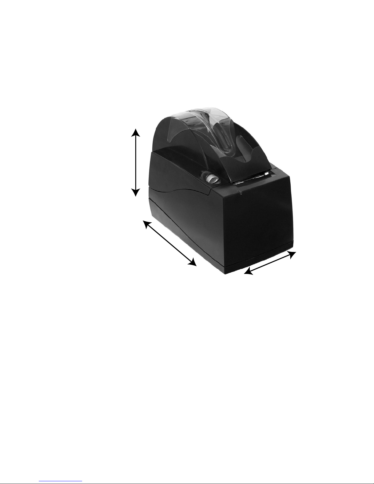
Mechanical Specifications
6.5 “ (165.1 mm)
13.26” (336.8 mm)
8.81” (223.77 mm)
• Height: 8.81" (223.77 mm)
• Width: 6.5" (165.1 mm)
• Depth: 13.26" (336.80 mm)
Introduction
Service Manual for the Accutherm Ultra Printer 1-3
• Weight: Approximately 4.9 lbs, 2.22 kg.
• Inter
• Printer Type: Fixed 80 mm.linear therma
face Type: USB
l head.
Page 16

Environmental Specifications
• Operating Temperature Range:5°C ~ 50°C (41°F ~ 122°F)
• Shipping/Storage Temperat ure Range:-10°C ~ 50°C (14°F ~ 122°F)
• Operating Humidity Range:10% ~ 90% @ 40°C (104°F) noncondensing only
• Shipp
ing/Storage Humidity Range:10% ~ 90% non-condensing only
(excluding paper)
Electrical Specification
AC Power Requirements: The Accutherm Ultra Printer is designed to be AC
self-powered. The printer is equipped with a universal input power supply that is
designed to operate worldwide without modification.
Supply
Supply Voltage
Rating (VAC)
100-240 90-264 47-63 20 watts
Voltage Range
(VAC)
Frequency
(Hz) Power Consumption
1-4 GTECH Technical Training and Support Services
Page 17

Standard Printer Features
Standard features of the Accutherm® Ultra printer include:
• High-speed (10 inches per second) thermal receipt printing
• Black dot - Top of Form and Paper Low Sensing capabilities
• Jam Detection
• Multiple barcode printing capabilities
•2 of 5
• EAN-8
• EAN-13
•UPC-A
•3 of 9
•UPC-E
•Codabar
Introduction
• Code 128
• Code 93
• PDF417 2D Stacked
•Data Matrix
• RSS GS1
• Print-Line Width of 640 dots @ 8 dots/mm centered on 3.25 in (82.5 mm)
Paper
•
Up to a 7.5 in (190 mm) Diameter Paper Roll
• Long-life auto ticket cutter
• Standard variable length stacking module capable of handling from 2.75 to
10 inch (70 to 254 mm) length tickets
• Ticket stacking capability (greater than 75 tickets)
• Modular printer design for easy servicing
• Internal Auto-Ranging (90-264 VAC) Power Supply
• Power and Error LED Indicator
• User Flash Memory
• 1M bytes User Graphics Memory
• Font/System Flash Memory:
Service Manual for the Accutherm Ultra Printer 1-5
• 128K bytes User Data Memory
• 2M bytes for Fonts and System files.
Page 18

• Manual configuration mode
• Self test diagnostics
• Loadable Enhanced Diagnostics
• USB interface built into main controller PCB
1-6 GTECH Technical Training and Support Services
Page 19
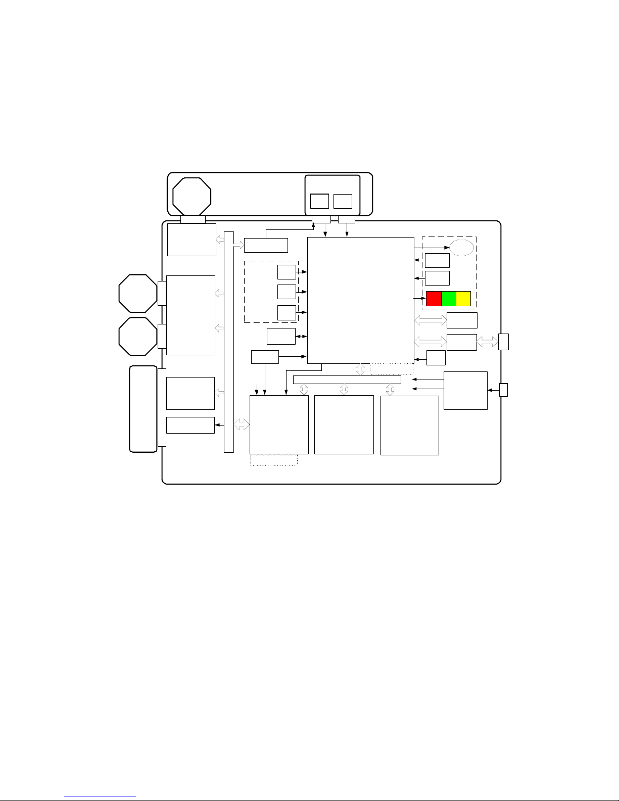
Mechanism
Top C ov e r
Paper Feed
Motor
Dual Step Motor
Driver
Allegro A 3988
(1000ma)
Step Motor Driver
Allegro A3 983
(400ma)
Knife Motor
Stack er Moto r
MCF5353
Processor
(BGA)
RAM
4Mb x 1 6
(BGA)
FLA SH
2Mb x 16
(BGA)
FPGA
(BGA)
Print
Head
Power Supply
and So ft Start
Address/Data Bus
+
Clock
Oscillator
Cover
EEPROM
RS2 32
Driver
+24 VDC
from
internal
power
brick
+3.3V
+1.5V
Paper
Cut
Home
TOF JAM
On board
sensors
(Interruptive)
Off board sensors
(reflective)
TOF Cur r e n t
Adjust
F
P
G
A
I
/
O
+
Print Head
Buffer
Print Head
Voltage Contro l
LED
Test
Switch
Feed
Switch
On Board
Operator
Inte rface
LED LED
USB
Protection
Beeper
USB
Clock
Debug Header
Program Header
Not
Populated
+1.5V
This section explains the Accutherm Ultra’s theory of operations.
Introduction
Print Head
The print head in the Accutherm Ultra is a high speed, thick film device
configured as single row of 640 dots spaced at 8 dots/mm for a total printable
width of 80mm (3.15”). Print data is sent from the controller board as a serial data
stream at 8 MHz.The head elements are then activated by signals from the main
controller board to form the image on the paper. The Accutherm Ultra uses a two
level energy control system to compensate for dot history with all timing
controlled by the controller board electronics. The head also contains a thermistor,
which is used to monitor the temperature of the head substrate. Dot energy is
continually adjusted based on head temperature, supply voltage, dot history, and
paper sensitivity. The print head connects to the controller through a 28 position
Flexible Flat Cable (FFC).
Figure 1-1. Printer Block Diagram
Service Manual for the Accutherm Ultra Printer 1-7
Page 20

Paper Motion
Paper motion is accomplished by a hybrid, 1.8 degree step motor running at a
maximum speed of approximately 3000 steps per second. The gear train is
designed such that one motor step equals.0833mm of paper motion resulting in a
paper feed speed of 250 mm/sec (10 in/sec).
Cutter
The cutter mechanism consists of a rotary blade mounted to the mechanism,
which operates against a fixed b lade located in the paper cover. The rotary blade is
driven by a 7.5 degree “tin can” step motor mounted to the mechanism frame,
acting through a lever arm and follower. The rotary blade home position is
determined by means of an optical sensor located on the controller board and a
flag located on the cutter drive gear. The motor operates one direction to activate
the cutter and then reverses direction to return the cutter to its home position with
a total cut cycle time of approximately 350 ms.
Sensors
There are two types of sensors used on the Accutherm Ultra printer. One type is
mounted directly on the controller board and is activated by mechanical flags on
the mechanism. These sensors are optical interruptive type and are used to detect
Cutter Home, Paper Out, and Cover Open conditions. The second type are
mounted in the printer mechanism and are connected by harnesses to the
controller. These are optical reflective sensors, which are used to detect black
marks and paper low stripes on the reverse side of the paper, as well as the
presence of tickets in the printer . Th e black mark/paper low detection sensor can
be auto-calibrated using on-board diagnostics.
Power Supply
The power supply for the Accutherm Ultra is a small, universal input, fully
enclosed module located within the printer cabinet. The 24 VDC output of the
supply connects to the controller board by means of a cable. The AC input
connector on the supply is accessible from the rear of the printer and accepts a
Standard, C6 style, 3-wire power cord.
1-8 GTECH Technical Training and Support Services
Page 21

Control Electronics
Overview
The printer has a main controller board containing microprocessor, FPGA,
memory, motor drivers, and sensor conditioning circuits used to control the
mechanism. The basic system clock was chosen to be 19.6608 Mhz. This clock is
multiplied in the main processor with a PLL to maximize execution speed and
used by the FPGA for optimum thermal print head load speed. External
communications is USB only.
Processor and Memory
The processor used in the Accutherm Ultra is a Motorola ColdFire MCF5253
running at 140 Mhz. with integrated USB controller. The processor interfaces,
through a 16 bit external bus, to a 64Mb Synchronous Dynamic Ram (SDRAM),
32Mb of Flash Memory, 8Kb of EEPROM, and a 2,910 logic element Field
Programmable Logic Array (FPGA). The processor contains general purpose I/O
pins which are used to directly control many of the printer functions including:
Introduction
• Status LEDs
• USB Communications
• Print Head Data and Timing
• Print Head Temperature and Voltage monitoring
• Programming the FPGA
The remaining printer functions are
• Stacker motor control
• Cutter motor control
• Paper feed motor control
• Thermal print head loading and protection
controlled though the FPGA including:
Service Manual for the Accutherm Ultra Printer 1-9
Page 22

Print Head Interface
Print data is formatted by the MCF5253 and transmitted to the FPGA through a
byte serial, memory mapped I/O interface for each dot row. This interface allows
rapid transmission of data with minimal software overhead. Once the transmission
is completed, the FPGA parses, loads, and latches the data into the print head
registers using two simultaneous serial channels. Strobe timing (dot energy
control) is calculated and applied to the print head by the MCF5253. For each line
of dots printed, the head is energized twice to compensate for dot history. The
MCF5253 provides a watchdog timer that is gated in the FPGA with the strobe
signals to protect the thermal print head from overheating. All head interface lines
are buffered and resistance matched to the connecting ribbon cable.
Motor Controllers
Both the paper feed and cutter step motors are controlled by an Allegro A3988
DMOS motor driver that provides two dual-bridge, bipolar, PWM, micro-stepping
motor drivers. These drivers operate from the 24-volt supply and apply up to
1.5A/phase of output current. The drivers are micro-step capable; the controller
must provide both phase and current level information to the driver . S tepper motor
control lines are driven by FPGA outputs latched from MCF5253 processor.
The paper feed motor is set for a maximum motor current of 1A/ phase. Control
lines operate this stepper motor in ¼ step mode up to approx. 500 equivalent full
steps/sec followed by modified half step mode up to 3600 equivalent full steps/
sec.
The cutter motor circuit is also set for a maximum current level of 1A/ phase.
Control lines operate this stepper motor in modified half step mode up to approx.
1000 equivalent full steps/sec.
The stacker motor is controlled by a dedicated Allegro A3983DMOS microstepping motor driver with translator. The driv er i s configured to operate the
stacker motor in modified half step mode at a maximum current of 500ma/phase
and is matched for stepping speeds to receive tickets passed off from the paper
feed motor.
1-10 GTECH Technical Training and Support Services
Page 23

Sensor Interface
There are three, on-board infrared optical interruptive sensors, which are activated
by plastic flags attached to the mechanism. These devices have an open collector,
photo transistor output and provide a low level signal when blocked. The output
switches to a high level when the sensor is unblocked by a flag. The outputs of
these sensors are buffered with Schmitt triggers before being presented as inputs
to the MCF5253. The state of these sensors is as follows:
The controller board also has connections for two external optical reflective
sensors. One sensor is used to detect the Top of Form (TOF) mark and paper low
stripes on the back of the paper. The other sensor is used to detect paper jam
(JAM) conditions.
Introduction
Table 1-1. Sensor State
Sensor Blocked Unblocked
OP1 Cutter home Cutter not home
OP2 Paper cover closed Paper cover open
OP3 Paper present Paper not present
The LED current of the TOF/Paper Low sensor is adjustable by the processor in 8
steps from 8ma to 21ma and is auto calibrated using diagnostics resident in the
printer. The output of this sensor is presented in analog form to the MCF5253’s
AD converter for calibration and Schmitt trigger buffered on another input for fast
reading during normal operation.
The LED current of the JAM sensor is fixed to approx. 18ma. Its output is Schmitt
trigger buffered for fast reading by the MCF5253 processor.
Power Supply Circuitry
There are four different power supply voltages used in the Accutherm Ultra.
Table 1-2. Power Supply Circuitry
Voltage Derived From Used For
24 VDC Modular Power Supply Print Head, Step Motors
3.3 VDC Derived from +24V using a buck
converter circuit
Processor I/O,USB
communications, SDRAM, flash
memory, print head logic,
sensors
Service Manual for the Accutherm Ultra Printer 1-11
Page 24

Table 1-2. Power Supply Circuitry
Voltage Derived From Used For
1.8 VDC Derived from 3.3V using an internal
regulator resident in the MCF5253
1.5 VDC Derived from 3.3V using a TI
TPS73601 low drop linear regulator
A power supply supervisor chip monitors the 3.3V and provides reset control for
the processor and FPGA.
Communications Interface
The communications interface is resident on the main controller PCB. The
Accutherm Ultra is available with one interface; USB.
Processor core
FPGA core
1-12 GTECH Technical Training and Support Services
Page 25

Installation
Introduction
Follow the instructions in this chapter in order to properly install the Accutherm®
Ultra printer. The Accutherm® Ultra can be used with a number of GTECH
terminals, including the GT1100 and GT1200.
2
GTECH hardware products and peripherals require properly grounded outlets. It
is critical that this grounding requirement is enforced on all installations of
GTECH hardware products and peripherals.
Service Manual for the Accutherm Ultra Printer 2-1
Page 26
Installation Instructions
Accutherm® Ultra
Printer
The following steps describe the procedure for installing the Accutherm Ultra
printer:
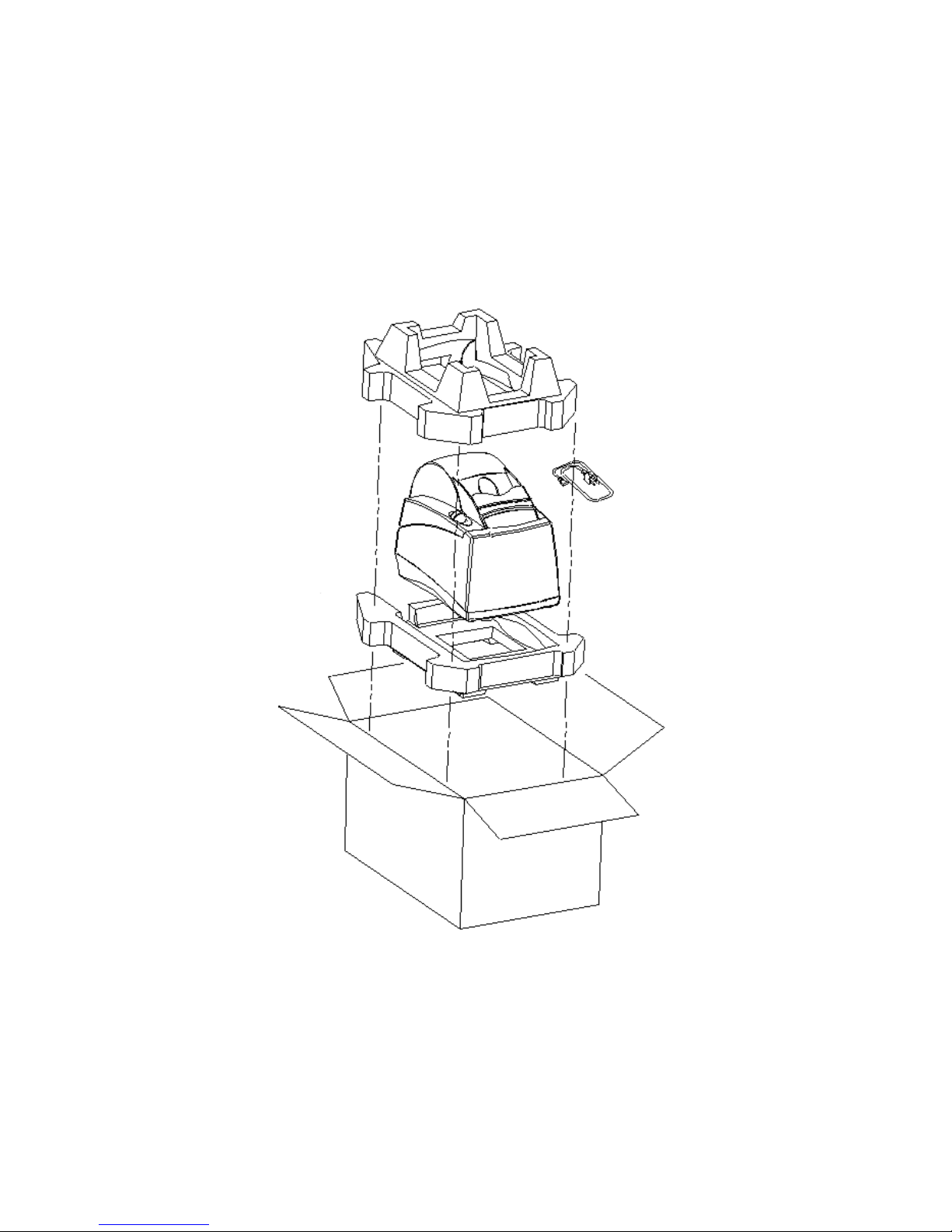
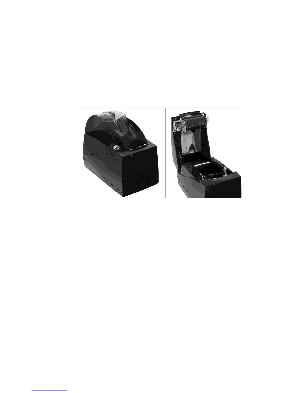
1. Remove the printer and cables from its pac
kaging.
Figure 2-1. Remove Accutherm Ultra from Packaging
2-2 GTECH Technical Training and Support Services
Page 27
Installation
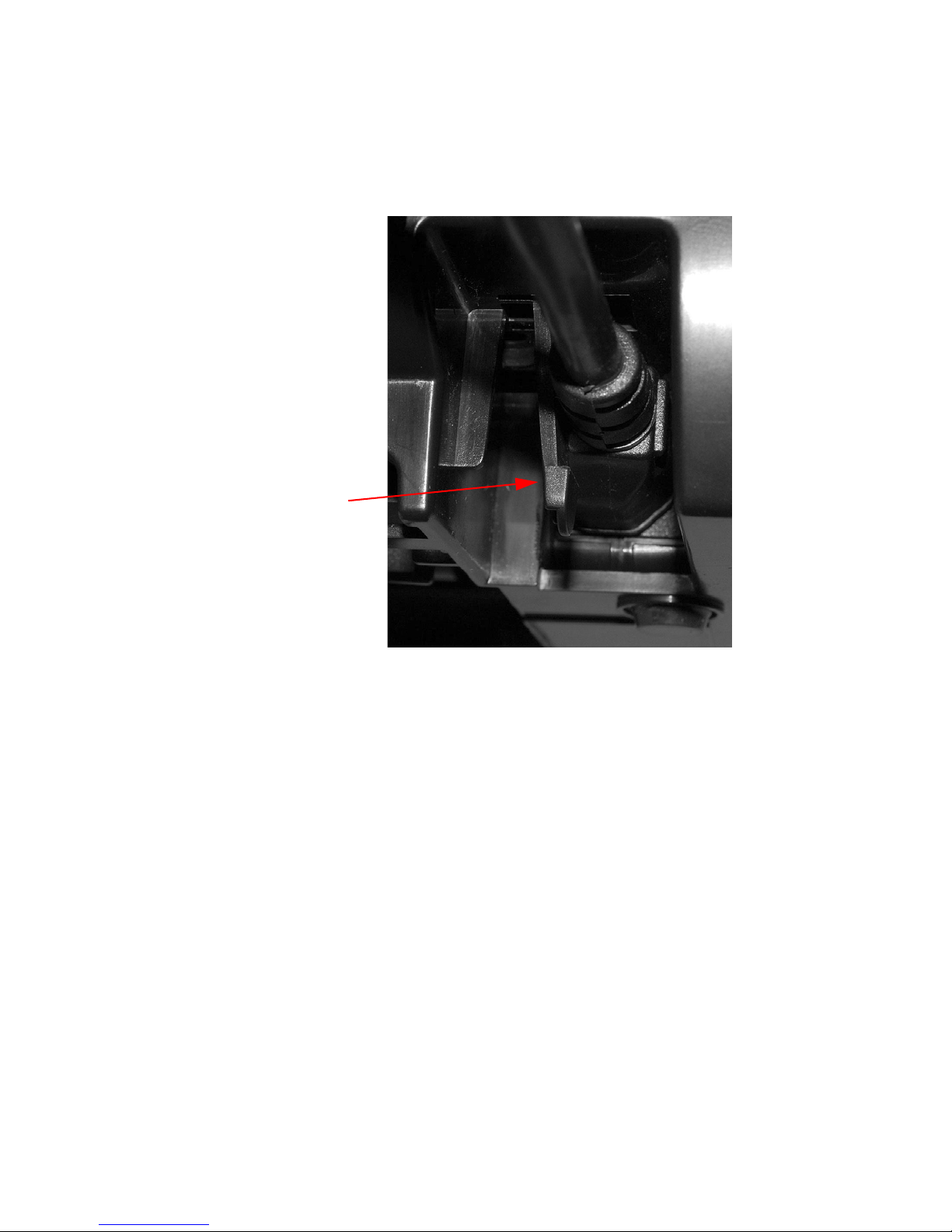
Strain Relief
2. Move the Strain Relief lever (Figure 2-2) to the left and then plug the power
cord into the power connector, located at t
he rear of the printer.
Figure 2-2. Plug Power Cord into P
rinter
Service Manual for the Accutherm Ultra Printer 2-3
Page 28
3. Plug the printer’s USB data cable into the Main Controller PCB, located on
Main Controller PCB USB
connection
Note how the USB cable routes
through the plastic guides on the
bottom of the printer.
the bottom of the Accutherm Ultra (Figure 2-3).
Figure 2-3. Plug USB Cable into Printer
2-4 GTECH Technical Training and Support Services
Page 29
Installation
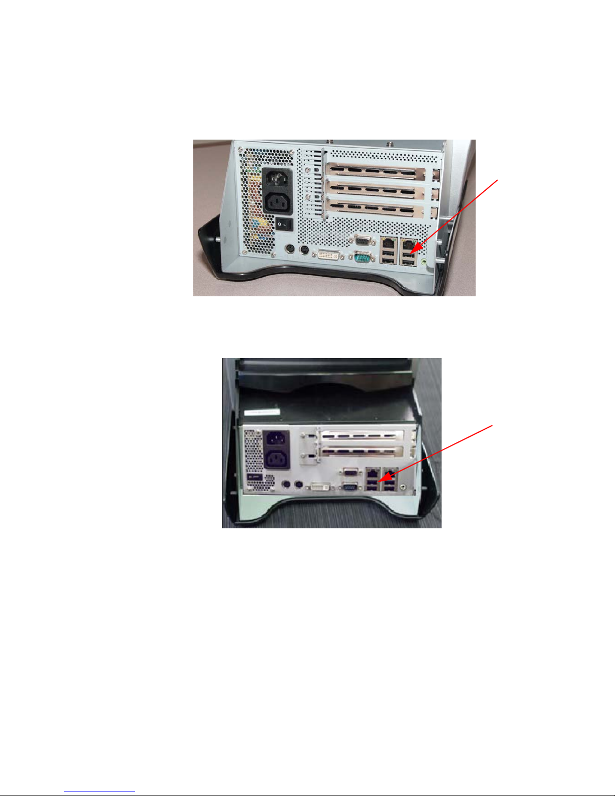
USB
USB
4. Plug the Accutherm Ultra’s USB data cable into the USB connector on your
terminal. See Figure 2-4 and Figure 2-5 for GT1200 and GT1 100 connections.
Figure 2-4. GT1200 USB Connection
5. Install a paper roll into the printer (see page 2-6 for paper loading
instructions).
6. Complete all required connections for
7. Apply power to both pieces of equipment.
Service Manual for the Accutherm Ultra Printer 2-5
Figure 2-5. GT1100 USB Connections
the terminal.
Page 30
Loading Paper
Follow the instructions below to load a new roll of paper into the Accutherm®
Ultra printer. Reference the photos that follow each step for the illustrated
procedure.
1. Press back on the gray cover latch button and raise
position.
2. T ear of f the first layer of the paper roll. Place the paper roll into the printer , so
that the paper unwinds from the bottom (front).
the paper cover to the open
3. Leave a few inches of paper outside of the printer.
2-6 GTECH Technical Training and Support Services
Page 31

Installation
4. Close the paper cover firmly so that it latches securely. Paper will feed
automatically to align itself and then the printer will automatically cut off the
excess paper.
Service Manual for the Accutherm Ultra Printer 2-7
Page 32

Page 33

Configuration
This chapter does not apply to the Service Manual for the Accutherm Ultra
Printer, as all printers are configured at manufacturing and updates are maintained
via the lottery terminal to which it is connected.
3
Service Manual for the Accutherm Ultra Printer 3-1
Page 34

Page 35

Operation
PLEASE NOTE!
There are no operating instructions for the Accutherm Ultra Printer, other than
installation and configuration. Please see Chapter 5, Diagnostics and Chapter 8,
Troubleshooting for information on problems encountered with powering up and
using the printer.
4
Service Manual for the Accutherm Ultra Printer 4-1
Page 36

Page 37

Diagnostics
The Accutherm® Ultra Printer provides printer self-test and diagnostics
features.This chapter provides information about these tests.
• “Printer Self Test” on page 5-2
• “Normal Operation Errors” on page 5-4
5
• “Extended Diagnostics” on page 5-6
Service Manual for the Accutherm Ultra Printer 5-1
Page 38

Printer Self Test
Service
Button
The Accutherm® Ultra printer is configured with two self-test operations.
• The first occurs each time the printer cover is closed and paper is present
after which, a receipt is printed that contains a header and the printe r
firmware revision and serial number.
• The second self-test is available by pressing the Service button as shown
in Figure 5-1 on the underside of the printer, at which time the printer
enters self-test mode.
Figure 5-1. Service Button Underneath Printer
When servicing the printer, you should verify the firmware version and serial
number that
5-2 GTECH Technical Training and Support Services
are printed on the receipt.
Page 39

Self-Test Mode
Pressing the Service button on the underside of the printer activates the self-test
mode that provides several print tests, plus access to the printer configuration and
factory tests.
To access the printer test display:
Diagnostics
1. Press and hold the Service button to
begin scrolling through the tests.
2. To select a test release the Service button at the desired test prompt,
follow the instructions.
The available printer test options
include the following:
• Print Test Ticket - Prints a sample ticket
• Print GTECH Ticket - Prints a GTECH sample ticket
• Configuration - Enters Configuration mode.
• User Stats – Provides information for 3 Groups
Group 1:
• Number of Line Feeds
• Characters Printed
• Cover Opens (sensor triggers)
• Paper Out (sensor triggers)
Group 2:
• Auto Cutter Cycles
• Auto Cutter Faults
then
• Pr
• Marker Calibration - Verifies that the Top of Form marker sensing is
• Continu
Service Manual for the Accutherm Ultra Printer 5-3
• Auto Cutter ReHome
Group 3:
• Level 1 Jams
• Level 2 Jams
int Head Test - Prints a test pattern to verify that all print elements are
working and clean.
working.
ous Print - Prints the test ticket continuously to verify stacker
functionality.
Page 40

Normal Operation Errors
During Normal operation, the Power LED remains on unless an error is indicated.
There are two classes of errors: soft errors and hard errors. Soft errors are
recoverable without power cycling the printer. Hard errors are not recoverable
without removing power from the printer, correcting the problem, and reapplying
power.
• Error Indicators
• Power -> Green
• Error -> Red
• Paper -> Yellow
Soft Errors
Soft errors may be recovered by the host or by opening and closing the printer
cover. All of these errors are indicated by a 5 second repeating blink pattern.
Soft Error State Indicators
Power (Green) Error (Red) Paper (Yellow)
Powering Down Fast Blink On Off
Cover Open 4 Blinks On Off
Print Head Over Temp 9 Blinks Slow Blink Off
Power Bad 2 Blinks Slow Blink Off
Out of Paper 2 Blinks On On
Jam 5 Blinks On Fast Blink
Missed Top of Form (TOF) 6 Blinks Off Fast Blink
Invalid Command 7 Blinks On Fast Blink
Paper Low Error On On Slow Blink
Paper Low On Off Slow Blink
Electronic Journal Low On Off 2 Blinks
5-4 GTECH Technical Training and Support Services
Page 41

Hard Errors
Hard errors have a similar pattern to Soft errors only they are slower and repeat
every 10 seconds. In general they occur during level 0 diagnostics and are not
recoverable.
Hard Error State Indicators
Power (Green) Error (Red) Paper (Yellow)
EEPROM read fault 2 Blinks On Off
EEPROM write fault 3 Blinks On Off
Error Vector Taken 4 Blinks On Off
Knife Error 5 Blinks On Off
Flash File system Error 7 Blinks On Off
Diagnostics
Flash Read/Write Error 9 Blinks On Off
Dynamic Memory Allocation 10 Blinks On Off
Font system Fault 11 Blinks On Off
Static Memory Allocation 12 Blinks On Off
Communications Fault 14 Blinks On Off
Kernel Fault 15 Blinks On Off
Head Connection Fault 16 Blinks On Off
NOTE! When the YELLOW and RED LEDs are illuminated at the
same time, the LED will illuminate as
ORANGE/AMBER.
Service Manual for the Accutherm Ultra Printer 5-5
Page 42

Extended Diagnostics
Accutherm® Ultra Extended Diagnostics are performed using the diagnostics on
the terminal to which the printer is connected. The printer may also be tested
using the general Terminal Qualify Diagnostics and further tested through the
Extended Diagnostics Peripherals menu.
5-6 GTECH Technical Training and Support Services
Page 43

Download
Downloads occur automatically via the terminal applicati on to which the printer is
connected. Should the RLT need to update the firmware manually, please contact
your Field Services Engineering (FSE) Representative or send an email to #Field
Services Engineering to obtain the latest and greatest firmware version for your
site.
6
Service Manual for the Accutherm Ultra Printer 6-1
Page 44

AccuTherm® Ultra Firmware Install Procedure
1. Connect the printer data cable to printer and
USB port in PC.
2. Connect the power cable to printer (do not
connect
3. Press and hold the diagnostics button while
ap
4. The LED on the front of printer will flash
slowly
(printer is in download mode (Transact boot loader)).
5. The USB Link is active and will communicate with the PC.
You must have the printer connected before starting the download
program. Otherwise, the download program will not see the USB port.
6. Run Download.exe.
7. Select the USB001
port or the active
USB port from the
drop-down menu.
to AC power yet).
plying power to printer.
. Release the diagnostics button
8. Click “Get Printer Information” to verify that you can communicate with the
printer.
9. To select firmware version:
a. click the “Select file to download” button.
b. Open the file containing the files you exported to the PC.
c. Double click PK5107_000_162Full.cbt file and select “Download Now”.
DO NOT INTERRUPT THE DOWNLOAD
The firmware file will be transferred to the pr
be activated if it is incorrect. The download program is not aware of the
verification process and assumes it loaded correctly.
You MUST wait at least 10 seconds after the download program says it’s
done as the printer takes 5 or 10 more seconds to finish writing the update to
flash. The easiest way to tell when the printer is done is to press the “Get
Printer Information” button after the download and when the printer
responds it’s done.
inter. It is self verifying and will not
6-2 GTECH Technical Training and Support Services
Page 45

Download
ADDITONAL INFORMATION:
The update has not yet occurred so the old revisions will be displayed, but
that’s OK. You can now power cycle the printer. (Wait at least 10 seconds
before re-connecting printer power for printer power supply to completely
discharge). Verify that the new firmware is active by opening and closing
the cover, then reading the printout.
Service Manual for the Accutherm Ultra Printer 6-3
Page 46

Page 47

Disassembly
Warranty Information
The Accutherm® Ultra Printer is under warranty from the manufacturer. Prior to
performing any printer disassembly, you MUST verify that the printer is out of
warranty with your Te chnical Services Manager. Performing any of the steps in
this chapter may VOID warranty and is therefore PROHIBITED until advised by
Management.
7
Caution: The Power Supply is
replaced in the field (FST) after warranty. All other subassemblies must
only be replaced by an RLT.
Before disassembling any part of the printer, be sure the power is
turned off. The Controller Board, the Thermal Print Head, and the
Interface Board can be damaged by static electricity. Observe ESD
precautions. Wear a grounded wrist strap and use a static mat or
other protected work surface.
Service Manual for the Accutherm Ultra Printer 7-1
the only sub-assembly approved to be
Page 48

Strain Relief
Thread Forming Screws - To prevent stripping the mating holes in
plastic components when replacing screws, turn the screw counterclockwise until a “click” is heard, then tighten normally.
Required Tools
The following tools are required to disassemble the Accutherm® Ultra printer:
• #1 Phillips screwdriver
• 5.5mm nut driver or wrench
Disconnect the Power Cable
To disconnect the power cable:
1. Unplug the power connector, located at the
2. Move the strain relief to left
while disconnecting the cable (Figure 7-1).
rear of the printer.
Figure 7-1. Disconnect Power Cable
7-2 GTECH Technical Training and Support Services
Page 49

Disassembly
Note that the
USB cable is
routed along the
bottom of the
printer via plastic
guides.
USB cable
connector
Disconnect the USB Communications Cable
To disconnect the USB data cable:
Unplug the USB cable from the Main Controller PCB, located on the
bottom of the printer (Figure 7-2).
Figure 7-2. Disconnect USB Cable
Service Manual for the Accutherm Ultra Printer 7-3
Page 50

Remove the Cover Assembly
# 6 Screws
To remove the cover assembly:
1. Open the Paper Cover Assembly and remove the Paper Roll, if present.
2. Turn the printer over and remove the four
the Midframe (Figure 7-3).
(4) #6 screws holding the Base to
7-4 GTECH Technical Training and Support Services
Figure 7-3. Remove Screws Holding Base
to Midframe
Page 51
Disassembly
# 6 Screws
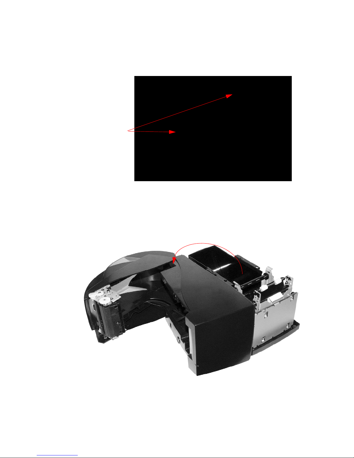
3. Unscrew two (2) #6 thread-forming screws, holding Mid-frame to Paper
Bucket (Figure 7-4).
Figure 7-4. Remove Screws Holding Midframe to Paper
Bucket
4. Lift and rotate the Mid-frame/Cover Assembly sideways, and then separate it
from the Ba
se Assembly, as shown (Figure 7-5).
Figure 7-5. Separate Midframe/Cover from Base Assembly
Service Manual for the Accutherm Ultra Printer 7-5
Page 52

5. Unplug the Top of Form Harness Assembly, Anti-Jam Sensor Harness
5
6
Assembly, Stacker-Motor Harness Assembly, and Power Supply Connector
from the Main Controller PCB Assembly.
6. Unplug the Ground Wire from the Printer Mechanism.
Figure 7-6. Unplug Harness Assemblies
7-6 GTECH Technical Training and Support Services
Page 53

Remove the Power Supply from the Base
Power Supply
Power Supply Release
Clip and Plug
Assembly
Disassembly
1. Unplug the Power Supply from the Main
press on locking clip to release the plug from the PCB Assembly (see inset).
2. Lift the Power Supply out of
When you reinstall the Power Supply, make sure that the label faces
inward; otherwise, it will not plug in correctly.
Service Manual for the Accutherm Ultra Printer 7-7
Figure 7-7. Remove Power Supply
Controller PCB Assembly. To do so,
the Base Assembly.
Page 54

Remove the Printer Mechanism Assembly
# 6 Screws
Printer
Mechanism
Make sure you
don’t lose or forget
to replace the
ground bracket
from the Base Assembly
REMEMBER TO USE ESD PRECAUTIONS
To remove the Printer Mechanism Assembly from the Base Assembly:
1. Remove four (4) #6 Thread Forming Screws holding the
Printer Mechanism
Assembly to the Base Assembly.
2. Rock the Printer Mechanism Assembly
and then slide it forward and out from
the Base Assembly. Slacker springs will separate from the bushings.
Figure 7-8. Remove Printer Mechanism Assembly from Base Assembly
7-8 GTECH Technical Training and Support Services
Page 55

Disassembly
Remove the Main Controller PCB Assembly
from the Printer Mechanism Assembly
REMEMBER TO USE ESD PRECAUTIONS
To remove the Main Controller PCB Assembly from the Printer Mechanism
Assembly:
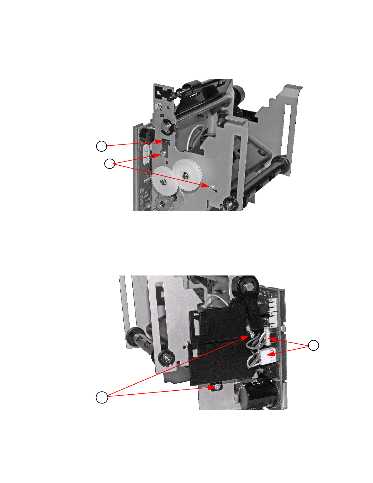
1. Unplug all connector Harness Assemblies from
callouts #5 and #6 in Figure 7-6 on page 7-6.
2. Make sure that the Power Supply cable is unplugged. See Figure 7-7 on
page 7.
3. Unplug the Thermal Print-head Ribbon Cable
See callout #2 in Figure 7-9 on page 7-10.
When reassembling the Thermal Print-head Cable make certain that
the full length of the connector is seated firmly and centered in the
mating connector on the Controller PCB and Thermal Print Head.
Otherwise, you could cause the print head to burn out.
4. Unscrew the four (4) M3 screws (callo
holding the Shield-PCB and the Main Controller
Mechanism Assembly.
ut #3 in Figure 7-6 on page 7-6)
the Main Controller PCB. See
from the Main Controller PCB.
PCB Assembly to the Printer
Service Manual for the Accutherm Ultra Printer 7-9
Page 56

1
3
2
Figure 7-9. Removing Main Controller PCB Assembly from Printer Mechanism Assembly
7-10 GTECH Technical Training and Support Services
Page 57

Disassembly
Remove the Print Head Assembly from the
Printer Mechanism Assembly (Lower Print
Mechanism)
REMEMBER TO USE ESD PRECAUTIONS
To remove the Print Head Assembly from the Printer Mechanism Assembly:
1. Rotate the Knife Stepper motor gear train unti
parallel to the bottom of the Printer Mechanism Assembly (Home position).
2. Orient the Printer Mechanism Assembly so that the Print-head Assembly
face
s you as shown in Figure 7-10 on page 12.
3. Push on the Print Head Assembly until the
from the alignment slots in the Paper Path Assembly.
4. Push down on the Print Head Assembly
Assembly toward you.
You should now be able to easily remove the Print Head Assembly.
When removing the Print Head assembly, be careful not to lose the
small tension spring behind it.
When reinstalling, make certain that the Rotary Knife Blade is parallel
to the bottom of the Printer Mechanism Assembly (Home Position), or
you may do damage to the blade, or the printer may fail to restart
without running it through a power cycle.
l the Rotary Knife Blade is
upper set of alignment pins escape
, and then rock the Print Head
Service Manual for the Accutherm Ultra Printer 7-11
Page 58

1
3
4
Position the Print Head
Assembly to face you.
Figure 7-10. Remove Print Head Assembly from Printer Mechanism Assembly
7-12 GTECH Technical Training and Support Services
Page 59

Disassembly
3
1
4
5
2
Remove the Rotary Knife from the Printer
Mechanism Assembly (Lower Print
Mechanism)
REMEMBER TO USE ESD PRECAUTIONS
To remove the Rotary Knife from the Printer Mechanism Assembly:
1. Rotate the Knife Arm forward until it clears the Gear Cover.
2. Remove the outside E-Clip, allowing
3. Remove the left and right E-Clips from
4. Remove the left and right bushings.
5. Press the Print Head in and down to provide
removal.
you to pull the arm off the shaft.
the Rotative Blade.
access for the rotary knife blade
Now you should be able to remove
the rotary knife blade.
Figure 7-11. Remove Rotary Knife from
Service Manual for the Accutherm Ultra Printer 7-13
Printer Mechanism Assembly
Page 60

Remove Paper Path Assembly from Printer
1
2
Mechanism
REMEMBER TO USE ESD PRECAUTIONS
1. Unplug Print Head cable from the PCB.
When reassembling the Thermal Print Head Cable ensure the cable is
centered in the mating connector on the PCB.
2. Remove the Print Head Assembly as shown in the section “Remove the Print
Head Assembly from the Printer Mechanis
Mechanism)” on page 7-11.
m Assembly (Lower Print
Figure 7-12. Remove Print Head Cable and Print
7-14 GTECH Technical Training and Support Services
Head Assembly
Page 61
3. Remove the two (2) #4 Thread forming Screws.
3
4
5
6
4. Remove the Print Head Ground.
Disassembly
Figure 7-13. Remove 2 Thread Forming sc
rews and Print Head Ground
5. Unplug connectors.
6. Remove two (2) M3 screws holding PCB Shield/Knife Motor
(Optional - Replace one (1) M3 screw to hold the
Motor in position for
remaining disassembly).
to frame.
Figure 7-14. Unplug Connectors and Remove Two (2) M3 Screws
Service Manual for the Accutherm Ultra Printer 7-15
Page 62

7. Remove E-Clip.
7
8
9
10
11
12
8. Remove Knife Arm.
9. Remove Rotative Blade Pin.
10. Remove three (3) Gears.
Figure 7-15. Remove E-Clip, Knife
Arm, Rotative Blade Pin and Three (3) Gears
11. Remove Two (2) #4 Thread Forming Screws.
12. Remove Print Head Ground.
Figure 7-16. Remove Two (2) #4 Thread
Forming Screws and Print Head Ground
7-16 GTECH Technical Training and Support Services
Page 63

Disassembly
13
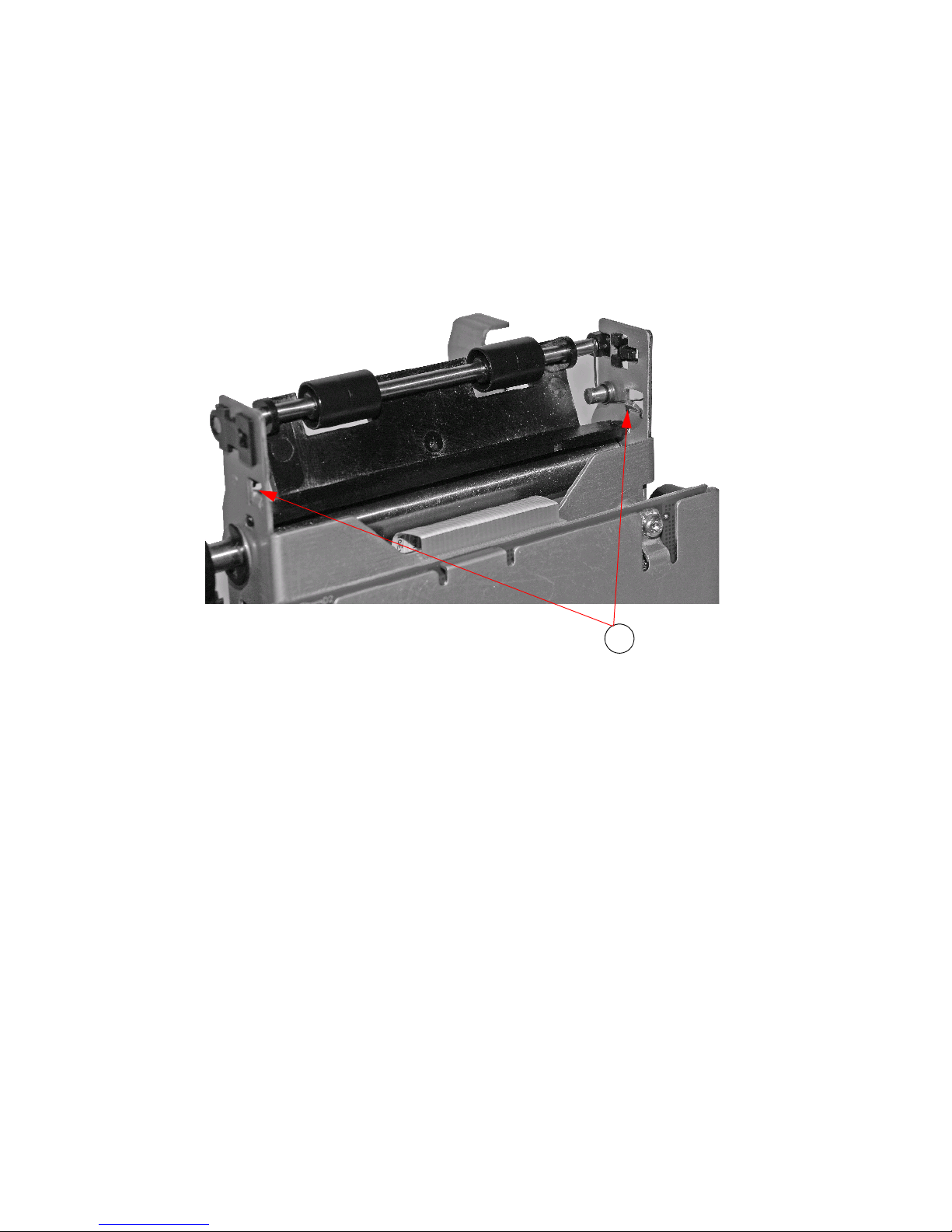
13. Remove Paper Path Assembly from Frame being careful not to damage sensor
flags.
Reassemble by reversing the previous steps, taking care that the locating
bosses are aligned with the mating holes in the frame.
Figure 7-17. Remove Paper Path Assembly from Frame
When reassembling the Thermal Print Head Cable ensure the cable is
centered in the mating connector on the PCB.
Service Manual for the Accutherm Ultra Printer 7-17
Page 64
Remove Stacker Guide Assembly from the
1
Printer Mechanism Assembly
REMEMBER TO USE ESD PRECAUTIONS
1. Unhook Left/Right Validation Compensatio
Figure 7-18. Unhook Validation Springs and Remove.
n Springs and remove springs.
2. Slide Stacker Shaft to the right to remove.
3. Remove two (2) Transport Rollers.
7-18 GTECH Technical Training and Support Services
Page 65

Disassembly
3
2
4
Figure 7-19. Slide Stacker Shaft to Right and Remove, then Remove Two Transport Rollers
4. Remove Stacker Guide from Frame being careful not to bend the
Reassemble reversing the above steps. Ens
ure the Compensation Bearings, the
frame tabs.
shaft and rollers move freely in the frame.
Service Manual for the Accutherm Ultra Printer 7-19
Page 66
Remove Platen from the Knife/Stacker
3
4
2
5
1
Assembly
REMEMBER TO USE ESD PRECAUTIONS
To remove the platen from the knife/stacker assembly:
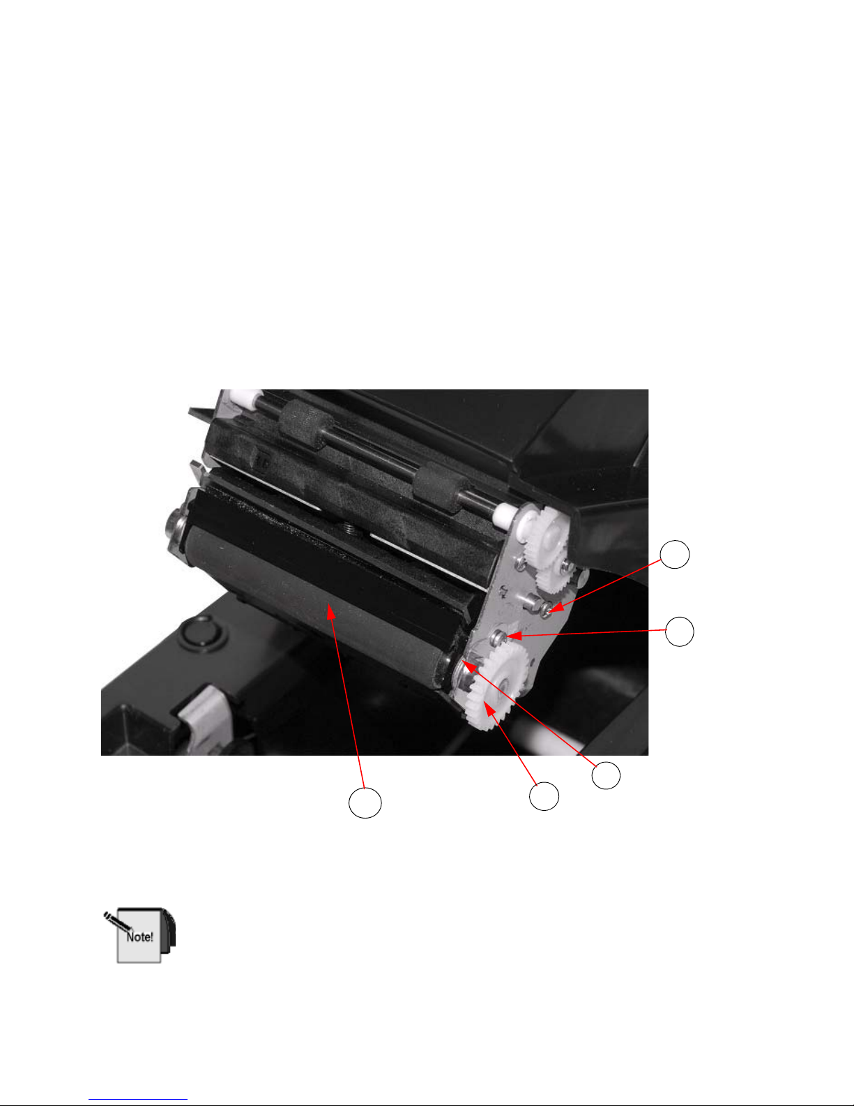
1. Remove the Platen Gear.
2. Loosen #4 thread forming screw -
3. Remove #4 thread forming sc
4. Remove Bearing Retainer - typ left/right sides.
5. Slide Platen, Stripper, and L/R bearings
typ left/right sides.
rew - typ left/right sides.
forward to remove from side plates.
Figure 7-20. Remove Platen from Knife
When installing Platen, Stripper, and Bearings ensure the Stripper
locating bosses are aligned with mating holes in the L/R Side Plates and
then tighten screws. Platen should spin freely when assembly is
completed.
7-20 GTECH Technical Training and Support Services
/Stacker Assembly
Page 67

Disassembly
1
1
2
Remove Fixed Blade from the Knife/Stacker
Assembly
REMEMBER TO USE ESD PRECAUTIONS
To remove the fixed blade from the Knife/Stacker Assembly:
1. Remove (6) #6 thread forming screws retaining knife/stac
cover.
Figure 7-21. Remove #6 Screws
2. Remove knife/stacker assembly from the
from the wire retention features in the cover.
paper cover. Remove wire harnesses
ker assembly to the
Figure 7-22. Remove Knife/Stacker Assembly from Paper Cover
Service Manual for the Accutherm Ultra Printer 7-21
Page 68

3. Remove Stacking Gear
3
4
5
6
7
4. Remove Stacking Gear/Retaining Ring.
5. Remove Platen Gear.
Figure 7-23. Remove Stacking Gear, Retaining Ring and Platen Gear
6. Remove one (1) #4 Thread Forming Screw.
7. Remove the Right Platen Bearing
Retainer.
Figure 7-24. Remove Screw and Right Platen Bearing Retainer
7-22 GTECH Technical Training and Support Services
Page 69

8. Remove one (1) #4 Thread Forming Screw.
8
9
10
11
9. Remove the Left Platen Bearing
Retainer.
Disassembly
Figure 7-25. Remove #4 Screw
and Left Platen Retainer
10. Remove Stacker Bearing.
11. Remove two (2) #4 Thread Forming screws.
Figure 7-26. Remove Stacker Be
Service Manual for the Accutherm Ultra Printer 7-23
aring and Two (2) #4 Screws
Page 70

12. Remove Right Side Plate Assembly.
12
13
14
13. Remove Platen, Stripper, a
nd L/R Platen Bearings.
Figure 7-27. Remove Right Side Plate Assy, Platen, Stripper, and L/R Platen Bearings
14. Remove Fixed Blade Spring.
Figure 7-28. Remove Fixed Blade Spring
7-24 GTECH Technical Training and Support Services
Page 71

15. Remove Latch Arm Hub.
15
16
16. Remove Retaining Ring.
Disassembly
Figure 7-29. Remove Latch Arm Hub and Retaining Ring
Position remaining assembly in a vertical orientation for
disassembly.
remaining
Figure 7-30. Position Remaining Assembly Vertically
Service Manual for the Accutherm Ultra Printer 7-25
Page 72

17. Remove Knife Pivot Shaft.
17
18
19
18. Remove Latch Arm Pivot
19. Remove Fixed Blade Assembly.
Figure 7-31. Remove Knife Pivot Shaft, Latch Arm Pivot, and
Fixed Blade Assy
7-26 GTECH Technical Training and Support Services
Page 73

20. Ensure Latch Arm Hub is in proper location for reassembly.
20
Disassembly
Figure 7-32. Check Location of Latch Arm Hub
Reverse Steps 1 through 20 for reassembly.
When installing Platen, Striper, and Bearings, ensure the Striper
locating bosses are aligned with the mating holes in the Left and Right
Side Plates, and then tighten screws. Platen should spin freely when
assembly is complete.
Service Manual for the Accutherm Ultra Printer 7-27
Page 74

Page 75

Troubleshooting
Introduction to Troubleshooting
These steps are a general guideline for Field Service Technicians to follow in the
event of a specific fault. After each step, the printer should be checked to
determine whether or not the step cleared the fault. If the fault is not cleared with
the first step, the next step is performed in an attempt to clear the fault on the
printer. If the fault cannot be cleared, the printer should be sent for repair.
8
Prior to performing any of the FST or RLT steps that follow, ensure that the
printer’s warranty status has been determined. If a printer is still In-Warranty, you
may only perform cleaning procedures in an attempt to clear a fault, disassembly
procedures are not allowed. Any hard failures must be sent to the OEM for repair.
These steps are a general guideline for RLT’s to follow in the event of a specific
fault. After each step, the printer should be checked to determine whether or not
the step cleared the fault. If the fault is not cleared with the first step, the next step
is performed, and so on until the fault is cleared or until the problem is further
identified.
Performing the steps in this chapter may VOID the warranty and is
therefore PROHIBITED until advised by Management.
Service Manual for the Accutherm Ultra Printer 8-1
Page 76

Troubleshooting Steps for FST’s
Problem Action
Printing
correctly
In
Colored stripe on the
receipt
Print is light or spotty 1 . Make su re the paper is loaded correctly
Vertical column of
print is missi
Receipt does not come
all of
the way out
Printer starts to print,
but stops while the
eceipt is being
r
printed
ng
1. Check the paper level.
2. If paper is low, change th
“Loading Paper” on page 3-6.
3. Clean the Top-of-Form / Paper Low sensor
w
ith 91% isopropyl alcohol and cotton swabs.
See “Cleaning the Top-of-Form/ Paper Low
Sensor” on page 9-3.
4. Swap the printer.
to “Loading Paper” on page 3-6.
2. Ensure the use of the recommended thermal
receipt paper
3. Swap the printer.
Swap the printer
1.Open the receipt cover and clear any jammed
paper. Refer to “Clearing a Paper Jam” on page
8-10).
2. Swap the printer.
1.Open the receipt cover and clear any jammed
paper. Refer to “Clearing a Paper Jam” on page
8-10).
2. Swap the printer.
.
e paper. Refer to
. Refer
Receipt is not cut 1. Open the receipt cover and clear any jammed
One side of receipt is
missing
8-2 GTECH Technical Training and Support Services
. Refer to “Clearing a Paper Jam” on page
paper
8-10).
2. Swap the printer.
Swap the printer.
Page 77

Problem Action
Troubleshooting
Printer Is Not
Working
Printer Status
D is
LE
blinking
No Power 1. Check that the terminal has power.
2. Check that printer cables are properly
co
nnected on both ends.
3. Ensure the latch and receipt cover is closed.
4. Verify the printer co
nfiguration and re-
configure if necessary.
5. Ensure that the printer is being operated in the
per room temperature (not too hot or too
pro
cold). If necessary, move the printer to a warmer/
cooler location.
6. Swap the Power Supply . Refer to “Remove the
Power Supply from the Base Assembly” on page
8-7.
7. Swap the printer.
During Normal operation, the Power
LED remains on unless an error is
indicated. There are two classes of
errors: soft and hard. Soft errors are
recoverable without power cycling the
. Hard errors cannot be recovered
printer
from without removing power from the
printer, correcting the problem, and
then reapplying power.
Error Indicators:
• Power—Green
Error—Red
•
• Paper - Yellow
Note: Wh
en the Indicators for Error and Paper are both illuminated an
Orange/Amber color displays.
Soft Errors: Soft errors
may be recovered by the host or by opening and
closing the printer cover. The following soft errors are indicated by a 5
second repeating blink pattern. Refer to “Soft Errors” on page 5-4 for
specific error information.
Out of Paper 1. Change the paper. Refer to “Loading Paper”
on page 3-6.
2. Swap the printer.
Paper Low Error 1. Change the paper. Refer to “Loading Paper”
on page 3-6.
2. Swap the printer.
Service Manual for the Accutherm Ultra Printer 8-3
Page 78

Problem Action
Printer Status
LED is
blinking
(contin.)
Cover Open 1. Close the printer cover securely.
2. Swap the printer.
Jam Detected 1.Open the receipt cover and clear any jammed
. Refer to “Clearing a Paper Jam” on page
paper
8-10.
2. Swap the printer.
Missed Top of Form
OF)
(T
1. Clean top-of-form sensor with 91% isopropyl
alcohol and cotton swabs.
2. Swap the printer.
Invalid Command 1. T urn the printer off, wait
60 seconds, then turn
it on again.
2. Swap the printer.
Printer Head Over
mperature
Te
1. Ensure that the printer is being operated in the
proper room temperature (not too hot or too
cold).
2. If necessary, move the printer to a warmer/
cooler location.
3. Swap the printer.
Power Problem 1. Turn the printer off, wait
60 seconds, then turn
it on again.
2. Swap the printer.
Hard Errors:
Hard errors have a similar pattern to Soft
repeat every 10 seconds.
In general they occur during level 0 diagno
all cases of Hard Errors, swap the printer.
errors only they are slower and
stics and are not recoverable. In
8-4 GTECH Technical Training and Support Services
Page 79

Troubleshooting Steps for RLT’s
Problem Action
Troubleshooting
Printing
orrectly
Inc
Colored stripe on the
receipt
Print is light or
spotty
Missing Print Replace the print head. Refer to “Remove the
1. Check the paper level.
2. If paper is low, change the paper. Refer to
“Loading Paper” on page 8-8.
3. Clean the Top-of-Form / Paper Low sensor
with 91%
1. Make sure the paper is loaded correctly
to “Loading Paper” on page 8-8.
2. Ensure the use of the recommended thermal
rece
3. Clean thermal print head with 91% isopropyl
alcohol
4. Check thermal print head cable connections
5‘. Replace the printer mechanism. Refer to
“Remove the Printer Mechanis
the Base Assembly” on page 7-8.
Print Head Assembly from the Printer
Mechanism Assembly (Lower Print
Mechanism)” on page 7-11.
isopropyl alcohol and cotton swabs.
. Refer
ipt paper.
and cotton swabs.
m Assembly from
.
Vertical column of
s missing
print i
Receipt does not
come
all of the way
out
Printer starts to
but stops while
print,
the receipt is being
printed
Service Manual for the Accutherm Ultra Printer 8-5
Replace the print head. Refer to “Remove the
Print Head Assembly from the Printer
Mechanism Assembly (Lower Print
Mechanism)” on page 7-11.
Open the receipt cover and clear any jammed
paper. Refer to “Clearing a Paper Jam” on page
8-10.
Open the receipt cover and clear any jammed
paper. Refer to “Clearing a Paper Jam” on page
8-10.
Page 80

Problem Action
Printing
Incorrectly
(contin.)
Sensors are not
working
operly
pr
Printer Errors
LED is blinki
ng
Error Indicators:
Power -> Green
Error -> Red
Paper -> Yellow
Receipt is not cut 1. Open the receipt cover and clear any jammed
paper. Refer to “Clearing a Paper Jam” on page
8-10.
2. Check the connections to the Main Controller
B.
PC
3. Replace the Main Controller PCB Assembly.
4. Replace
the printer mechanism. Refer to
“Remove the Printer Mechanism Assembly from
the Base Assembly” on page 7-8.
1. Open the printer.
2. Remove the printer cover.
3. Clean the optical sensors (Paper Out, Top-ofForm/Paper
Low , Anti-Jam, and Paper Cover
Opened) with isopropyl alcohol and cotton
swabs.
Soft & Hard Errors:
Soft Errors: Soft errors may be
recovered by the host or by opening
and closing the printer cover. All of
these errors are indicated by a 5 second
repeating blink pattern. Refer to “Soft
Errors” on page 5-4 for specific error
information.
Out of Paper 1. Change the paper. Refer to “Loading Paper”
on page 8-8.
2. Clean all sensors with 91% isopropyl alcohol
and cotton
swabs.
3. Replace the Main Controller PCB Assembly.
Paper Low Error 1. Change the paper. Refer to “Loading Paper”
on page 8-8.
2. Clean all sensors with 91% isopropyl alcohol
and cotton
swabs.
3. Replace the Main Controller PCB Assembly.
Cover Open 1. Close the printer cover securely.
2. Clean all sensors with 91% isopropyl alcohol
and cotton
swabs.
3. Replace the Main Controller PCB Assembly.
8-6 GTECH Technical Training and Support Services
Page 81

Problem Action
Troubleshooting
Printer Status
LED is blinking
(contin.)
Missed Top of Form 1. Clean all sensors with 91% isopropyl alcohol
and cotton swabs.
2. Replace the Main Controller PCB Assembly
Jam Detected 1.Open the receipt cover and clear any jammed
pap
er. Refer to “Clearing a Paper Jam” on page
8-10.
2. Clean all sensors with 91% isopropyl alcohol
and cotton
swabs.
3. Replace the Main Controller PCB Assembly
Invalid Command 1. Turn the printer off and then on again.
2. Reload firmware.
Printer Head Over
T
emperature
1. Ensure that the printer is being operated in the
proper room temperature (not too hot or too
cold).
2. If necessary, move the printer to a warmer/
cooler location.
3. Replace the Main Controller PCB Assembly
.
.
.
Power Problem 1. Check that the terminal has power
.
2. Check that printer cables are properly
connected on both ends
.
3. Ensure the latch and receipt cover is closed.
4. Verify the printer configuration and reconfigure if ne
5. Ensure that the printer i
cessary.
s being operated in the
proper room temperature (not too hot or too
cold). If necessary, move the printer to a warmer/
cooler location.
6. Swap the Power Supply . Refer to “Remove the
Power Supply from the Base Assembly” on page
7-7.
7. Swap the printer.
Hard Errors:
Hard Errors have a similar pattern to Soft errors only they are
slower and repeat every 10
seconds. In general they occur during level 0 diagnostics and are not recoverable. Refer to “Hard
Errors” on page 5-5 for specific error information.
In all cases of Hard Errors, replace the printer mechanism. See “Remove the Printer Mechanism
Assembly from the Base Assembly” on page 7-8.
Service Manual for the Accutherm Ultra Printer 8-7
Page 82

Loading Paper
Follow the instructions below to load a new roll of paper into the Accutherm®
Ultra printer. Reference the photos that follow each step for the illustrated
procedure.
1. Press back on the gray cover latch button and raise
position.
2. T ear of f the first layer of the paper roll. Place the paper roll into the printer , so
that the paper unwinds from the bottom (front).
the paper cover to the open
3. Leave a few inches of paper outside of the printer.
8-8 GTECH Technical Training and Support Services
Page 83

Troubleshooting
4. Close the paper cover firmly so that it latches securely. Paper will feed
automatically to align itself and then the printer will automatically cut off the
excess paper.
Service Manual for the Accutherm Ultra Printer 8-9
Page 84

Clearing a Paper Jam
1. Press back on the cover latch
button.
2. Raise the paper cover to the Open
position.
3. Grasp the jammed paper and gently
pull t
o un-jam it from the inside of
the printer.
4. Advance the paper roll so that the
jammed portion
additional inches are outside of the
printer.
and a few
5. Close the paper cover firmly so
tha
t latches securely.
6. The paper will feed automatically
to align itself and
automatically cut off the excess
paper.
8-10 GTECH Technical Training and Support Services
the printer will
Page 85

9
Preventive Maintenance
General Cleaning
Be sure to follow ESD precautions when performing maintenance on
the printer. This is stressed particularly when performing any cleaning
of the print head, as ESD discharge directly onto the print head can
cause failures.
Once the unit is opened, the paper path is accessible for cleaning or clearing paper.
Use a soft brush to clean the paper dust from inside the printer. The paper dust
should also be removed from the sensor optics.
Service Manual for the Accutherm Ultra Printer 9-1
Page 86

Cleaning the Print Head
TO BE PERFORMED BY RLT ONLY USING ESD PRECAUTIONS
After printing, the print head can be very hot. Be careful not to touch it
and let it cool down before you clean it. Do not damage the print head
by touching it with your fingers or any hard object.
If streaking on the printed ticket is evident, the
cleaned (Figure 9-1). This can be with a cotton swab moistened with 91%
isopropyl alcohol.
thermal print head may need to be
Figure 9-1. Cleaning Print Head (Use ESD Precautions)
9-2 GTECH Technical Training and Support Services
Page 87

Preventive Maintenance
Cover Open and
Paper Out Indicators
Top-of-Form/
Paper Low
Sensor
Cleaning the Top-of-Form/ Paper Low Sensor
Clean the Top-of-Form / Paper Low sensor with a cotton swab moistened with
91% isopropyl alcohol (Figure 9-2).
Figure 9-2. Clean TOF Sensor and Check Paper Out Indicators
Service Manual for the Accutherm Ultra Printer 9-3
Page 88

Cleaning the Jam Detection Sensor
Platen
Jam
Detection
Sensor
Clean the Jam Detection Sensor with a cotton swab moistened with 91% isopropyl
alcohol (Figure 9-3).
Cleaning the Platen
Use a cloth dampened with alcohol to wipe the platen of any debris, as needed
(Figure 9-3).
Figure 9-3. Cleaning the Jam Detection Sensor and Platen
9-4 GTECH Technical Training and Support Services
Page 89

Handling Precautions
This chapter explains the proper handling of Electrostatic Discharge (ESD)
sensitive modules and devices, the proper transport of terminals and other parts,
how terminals and devices should be packaged for returns to depots or retailers,
and the proper storage of extra or backup devices and parts.
A
Service Manual for Accutherm Ultra Printer A-i
Page 90

ESD HANDLING
All GTECH Printed Circuit Boards (PCBs) are static-sensitive. In order to prevent
damage to electronic components through ESD, please take the precautions
presented in this chapter whenever:
• Performing any work on a PCBs and equipment containing PCBs
What is ESD?
Static is the electrical charge created by the friction of two dissimilar materials
moving against each other. Electro Static Discharge, or ESD, is the unintended
dissipation of that charge, typically by short circuiting the charge to another
device or to ground.
Our bodies can create as much as 25,000 volts of static electricity across our 100
to 250 picofarads of capacitance to ground. In the worst case work environment,
voltages on some objects could exceed 50,000 volts. This more than exceeds the
static-tolerance threshold of most transistors, resistors, op-amps, and digital
computer chips. Some MOS families, for instance, can be damaged by a charge as
low as 150 volts.
Usually the damage is such that it goes undetected for some time but eventually
creates either an intermittent or hard failure in the field. Insulators, or nonconductors of electricity, pose the greatest static discharge threat to electronic
devices because of their inability to bleed their static charges.
• Removing subassemblie
s or components
Becoming “Static Safe”
Equipment or component failures that result from ESD can be difficult to identify
but can be avoided at minimal cost with proper handling techniques.
A static electricity-safe workplace is an environment in which anything that can
generate static charges is eliminated or is drained of its charge. Such a workplace
employs conductive and static dissipative materials for its table tops, floor
surfaces, clothing, and material handling bins, boxes and bags. Machines, tools
and test fixtures should be properly grounded. Technicians or anyone handling
electronic components should wear wrist straps and even ankle straps at all times
when working on or near ESD sensitive electronic modules, PCBs and devices.
GTECH has created this chapter to help you identify ESD failures and to
implement correct handling procedures. Please read the following sections
carefully.
A-ii GTECH Technical Training and Support Services
Page 91

ESD-Induced Failure Modes
Radiated Electromagnetic Fields
Radiated electromagnetic fields induce low-level voltages in unshielded signal
conductors. These can cause intermittent unit halts from which the operator may
recover. Older products are more sensitive to these fields. Products manufactured
today are designed with covers and shielded external cables to protect them from
most induced voltages.
Conducted Charges
Conducted charges (usually at points where the operator touches the unit) may
transfer directly to components and result in either intermittent or permanent
failures.
Typical Symptoms of ESD Damage
Handling Precautions
Hard failures such as blown semiconductor junctions, cracked oxide layers, fused
metallization or bond wires can result from ESD, however, intermittent failures
are the most common result of ESD. The device becomes temperature sensitive,
input thresholds shift, output levels and drive ability degrade, etc.
Increased failure rates are also typical. Normal stresses such as temperature
swings, power surges, or another “zap” could permanently disable a device
previously exposed to ESD, even if no symptoms existed from the first exposure!
Common False Assumptions Concerning ESD
• MYTH: Only MOS devices are ESD sensitive.
FACT: All semiconductor materials are sensitive to ESD. Some devices
are just more sensitive than others.
• MYTH: A component cannot be damaged once it is installed in a board.
FACT: It may be even more susceptible to induced fields due to the
antenna effect of the etch or wire connected to it.
• MYTH: If the device works after I replaced it, I got lucky and did not
damage it.
FACT: Most failures are not catastrophic and only reveal themselves as
intermittent or latent failures.
• MYTH: A grounded metal table top is a good anti-static work surface.
Service Manual for Accutherm Ultra Printer A-iii
FACT: A much better way to dissipate electrostatic fields is to use an antistatic mat and a 1-Megohm discharge current limiting resistor c o n n e c t ed t o
earth ground so that the charge is drained in a controlled manner.
Page 92

• MYTH: Wrist straps present a personal shock hazard when working on
live circuits because they ground your body.
FACT: As long as the 1-Megohm resistor is connected between the strap
and the ground connection the wrist strap does not increase your risk of
suffering a shock hazard. The 1-Megohm resistor limits the current to a
safe value for low-voltage circuits.
• MYTH: We don’t take precautions and we don’t have ESD problems at
our depot.
FACT: You may not realize the damage that you are causing, but it is
there. GTECH Engineering can determine if hard and intermittent failures
are due to ESD damage by examining individual components, but such
damage is not something that a technician can readily identify.
• MYTH:
FACT: Our ter
like any other electronic device.
The GTECH terminal is not susceptible to static damage.
minals can be damaged or destroyed by static discharge just
ESD Precautions Checklist
Recommended Devices
• Wrist straps at the bench
• Wrist strap tester
• Only tools or parts made out of conducting materials (i.e., no plastic solder
vacuums, tweezers, etc.).
• 3M® anti-static vacuum cleaners
• Static-dissipative ma ts connected to earth ground for bench tops and
flooring
• Static-dissipative bags, boxes, bins and/or totes for handling PCBs (bags
and totes must remain closed during transport - no part of the item can
“stick out” of the bag or the bag is ineffective)
• Static-free floor mats, static-dissipative shelving, and 3M black conductive
PCB storage bags used at all times (stockroom)
A-iv GTECH Technical Training and Support Services
Page 93

Handling Precautions
Precautionary Practices
• Minimize handling of components.
• Keep parts in static-dissipative packaging until ready for use.
• Use ESD-protective containers for handling and transporting small
components.
• Handle IC’s by the body, not the leads.
• Do not slide static sensitive devices over any surface.
• Eliminate static generators from your work area, for example plastic, vinyl,
styrofoam, etc.
• Use a static-free workstation whenever handling parts in the office, in the
field or anywhere.
Recommended Handling - Example
A typical scenario for a technician at a bench to properly retrieve parts from a
stock area is as follows:
• You, the technician, are seated at a bench, connected to electrical ground
via a wrist strap.
• The bench surface has a clean, grounded, static-dissipative bench mat
connected to earth ground. All tools are conductive.
• When rising from the bench to retrieve a PCB (for example), disconnect
the wrist strap.
• Proceed to the storage location and back to the bench, keeping the board in
the exist i n g , c lo s e d static-dissipative packaging.
• Re-attach the wrist strap, remove the
the terminal, which is sitting on the static-dissipative mat.
NOTE!
After leaving and returning to the static-dissipative area, always
reconne
touching any static sensitive parts.
ct to a static wrist strap connected to electrical ground before
board from the bag, and install it in
Service Manual for Accutherm Ultra Printer A-v
Page 94

Proper Grounding Technique
RLTs and FSTs must follow proper ESD precautions. This includes the items
mentioned throughout this section: wrist straps, anti-static mats, anti-static
vacuum cleaners, and antistatic bags.
• FSTs in the field must be grounded by a wrist strap connected to the
terminal which in turn is connected to earth ground when servicing that
terminal and all boards being transported must be stored enclosed within
static-dissipative packaging.
• RLTs must work in a static-safe enviro
nment. The workbenches must have
anti-static mats which are connected to earth ground and the RLT must
observe proper ESD precautions, utilizing static wrists straps and proper
anti-static packaging.
Note!
Vacuum cleaners are generators of static electricity. When purchasing
a vacuum clea
ner, choose one with an antistatic nozzle (such as the
one recommended in the Spare Parts and Tools Chapter). If unable to
purchase antistatic vacuum cleaners, the nozzle of the hose must be
wrapped with antistatic (conductive) tape from the nozzle to the handle.
The picture below shows a properly grounded technician. Notice that the
technician is grounded to the anti-static mat and the mat is grounded to earth
ground at the AC outlet.
A-vi GTECH Technical Training and Support Services
Page 95

When servicing the terminal in the field the FST first must ground himself to the
terminal chassis which is powered off and connected to earth ground, as shown in
the picture below.
GTECH Manufacturing Specification
GTECH assemblies comply with IEC 61000-4-2 recommendations for severity
typically in excess of level three. IEC stands for International Electrotechnical
Commission. The specification is for Electromagnetic Compatibility for Industrial
Process Measurement and Control Equipment.
Handling Precautions
Part two specifies electrostatic discharge requirements and states that our
equipment must withstand 15KV air discharges and 8KV contact discharges. Both
positive and negative polarity discharges must comply.
Service Manual for Accutherm Ultra Printer A-vii
Page 96

PACKAGING
General Packaging Procedures
Package and ship all modules or devices in the packaging in which they were
received from the manufacturer, whenever possible. Make sure that the packaging
is in good condition and not damaged from previous shipping or handling.
• Circuit boards offer special problems and should be inspected for delicate
components and sharp objects. Contact Manufacturing Engineering for
assistance, if needed.
• All precautions must be made to insure that product that is shipped is not
deformed or altered due to packaging used. Consideration must be giv en to
the fragileness of the product that is shipped for total coverage of protective
materials.
• Appropriate sized labels, elastic bands, or ESD tape must be used for
securing ESD bags. Staples cannot be used.
• Multiple Circuit Card Assemblies' must be placed in a single static
shielding bag only if they are mechanically separated with conductive or
anti-static foam. No movement between assemblies can occur.
• As a priority, Circuit Card Assemblies' must be transported in slotted,
conductive totes, with dividers spaced for tight capture. If boards are very
short, anti-static bubble wrap or anti-static foam is used to prevent
movement from slotting during handling. When conductive totes/dividers
are not available, static shielding bags protect Circuit Card Assemblies'.
Separation of Circuit Card Assemblies' by means of anti-static bubble or
thin polyethylene foam sheeting is required. Fragile parts must be
cushioned from one board to another and no ‘puncturing’ of ESD
protection is allowed.
• All IC’s must be placed in anti-static tube holders that are cut to size; then,
placed in static shielding bags for transit in kit or sales orders. Shielding
bags must be fully closed and sealed. Static shielding bags may be replaced
by conductive DIP tube shippers or bin boxes.
• IC’s that will not fit an IC tube must be placed in conductive foam. All IC
legs are inserted in foam without deforming; then, placed in static shielding
bags for transport in kit or sales orders. Shielding bags must be carefully
closed and sealed properly.
• IC's must not be placed loose in bags.
• Parts which mark or scratch easily must use supplier packaging or must be
separated by thin foam, polybag material or corrugated in a similar fashion
to the original supplier packaging.
A-viii GTECH Technical Training and Support Services
Page 97
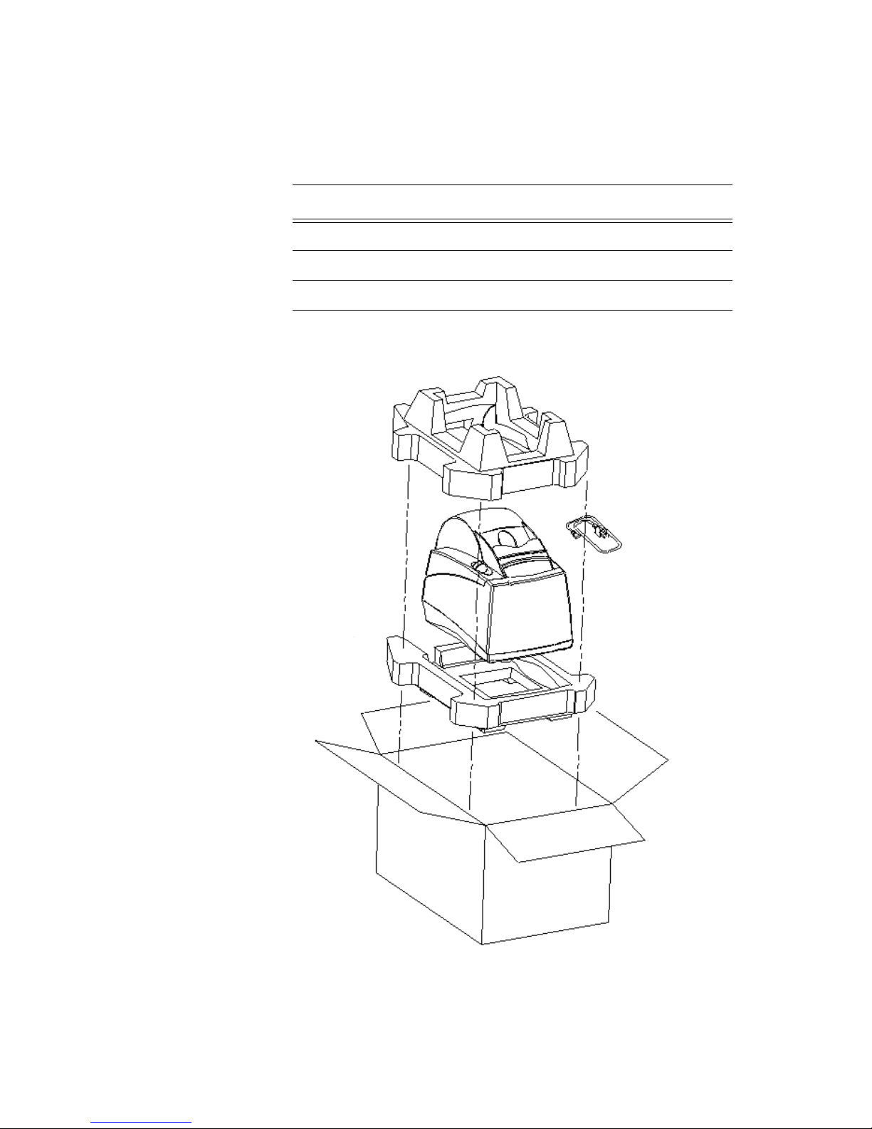
Handling Precautions
The same packing material is used for unpacking and packing the printer.
Description
Packset-M
280 GTECH EPS (Figure A-1)
Cord - Power IEC 60320 (Figure A-1)
Carton - EPS Foam (Figure A-1)
Service Manual for Accutherm Ultra Printer A-ix
Figure A-1. Unpacking and Packing the Printer
Page 98

Page 99

Diagrams
The following page includes the block diagram for the Accutherm Ultra Printer.
Please contact FSE Engineering, should you need additional information.
B
Service Manual for the Accutherm Ultra Printer B-i
Page 100

Figure B-1. Printer Block Diagram
Top C ov e r
Paper Feed
Motor
Dual Step Motor
Driver
Allegro A 3988
(1000ma)
Step Motor Driver
Allegro A3 983
(400ma)
Knife Motor
Stack er Moto r
MCF5353
Processor
(BGA)
RAM
4Mb x 1 6
(BGA)
FLA SH
2Mb x 16
(BGA)
FPGA
(BGA)
Print
Head
Power Supply
and So ft Start
Address/Data Bus
+
Clock
Oscillator
Cover
EEPROM
RS2 32
Driver
+24 VDC
from
internal
power
brick
+3.3V
+1.5V
Paper
Cut
Home
TOF JAM
On board
sensors
(Interruptive)
Off board sensors
(reflective)
TOF Cur r e n t
Adjust
F
P
G
A
I
/
O
+
Print Head
Buffer
Print Head
Voltage Contro l
LED
Test
Switch
Feed
Switch
On Board
Operator
Inte rface
LED LED
USB
Protection
Beeper
USB
Clock
Debug Header
Program Header
Not
Populated
+1.5V
B-ii GTECH Technical Training and Support Services
 Loading...