

Page 1
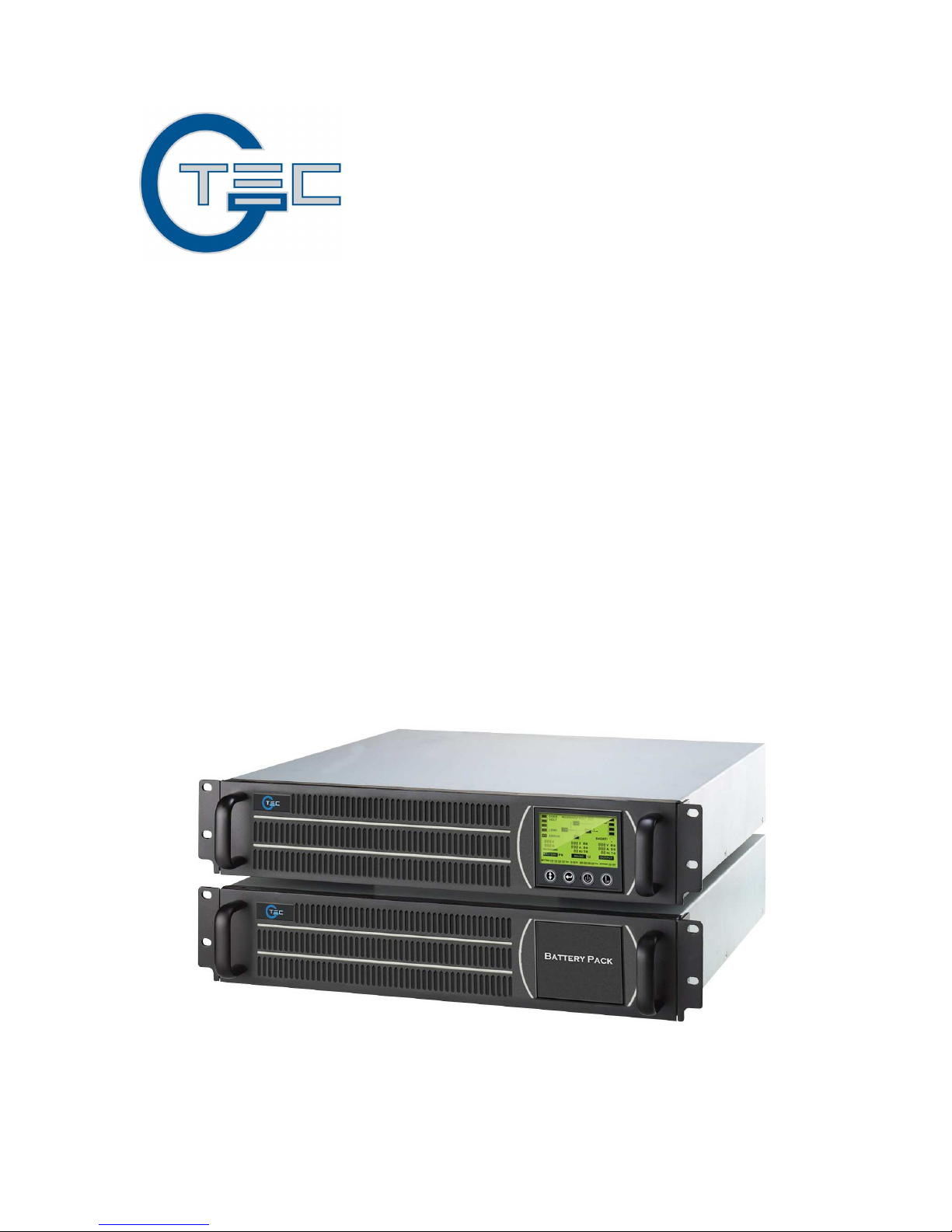
USER’S MANUAL
MANUALE UTENTE
For Models AP160LCD
1~6KVA
Uninterruptible Power System
Page 2

CONTENT
1. Safety and EMC instructions .............................................................. 1
1.1 Installation....................................................................................... 1
1.2 Operation ........................................................................................2
1.3 Maintenance, servicing and faults ..................................................2
1.4 Transport.........................................................................................3
1.5 Storage............................................................................................ 3
1.6 Standards........................................................................................ 4
2. Description of commonly used symbols...........................................5
3. Introduction ..........................................................................................6
4. Panel description ................................................................................. 7
5. Connection and operation................................................................. 11
5.1 Inspection:..................................................................................... 11
5.2 Connection:................................................................................... 11
5.3 Battery Charge:.............................................................................13
5.4 Turn On the UPS:..........................................................................13
5.5 Test Function:................................................................................13
5.6 Turn Off the UPS:..........................................................................14
5.7 Audible Alarm Mute Function:.......................................................14
5.8 Operation Procedure of External Battery for Long Backup time
Model (“S” Model) ...............................................................................14
6. Operating mode for all models.........................................................16
6.1 Line mode .....................................................................................16
6.2 Battery mode.................................................................................17
6.3 Bypass mode ................................................................................17
6.4 NO output mode............................................................................18
6.5 Abnormal mode.............................................................................19
7. Setting by LCD module...................................................................... 20
8. Trouble shooting................................................................................23
9. Maintenance........................................................................................ 25
9.1 Operation ......................................................................................25
9.2 Storage..........................................................................................25
10. Technical data................................................................................... 26
10.1 Electrical specifications...............................................................26
10.2 Operating Environment...............................................................26
10.3 Dimensions and weights.............................................................27
11. Communication port ........................................................................ 28
11.1 RS232 Interface ..........................................................................28
11.2 AS400 Interface (Option).............................................................28
12. Software for all models.................................................................... 29
Appendix .................................................................................................30
Page 3

ITALIANO
1. Istruzioni relative alla sicurezza e alla EMC................................34
1.1 Installazione ..................................................................................34
1.2 Utilizzo...........................................................................................35
1.3 Manutenzione, riparazione e guasti..............................................35
1.4 Trasporto.......................................................................................36
1.5 Stoccaggio.....................................................................................37
1.6 Standard........................................................................................37
2. Descrizione dei simboli di uso comune .......................................... 38
3. Introduzione........................................................................................ 39
4. Descrizione del pannello...................................................................40
5. Collegamento e utilizzo .....................................................................44
5.1 Ispezione:......................................................................................44
5.2 Collegamento:...............................................................................44
5.3 Caricamento della batteria:...........................................................46
5.4 Accensione dell’UPS:....................................................................46
5.5 Test di funzionalità: .......................................................................47
5.6 Spegnimento dell’UPS: .................................................................47
5.7 Funzione Muto per l’allarme sonoro: ............................................47
5.8 Procedura operativa della batteria esterna per modello a tempo di
backup esteso (Modello “S”)...............................................................48
6. Modalità operative per tutti I modelli ............................................... 49
6.1 Modalità normale (Presenza di tensione di rete)..........................49
6.2 Modalità batteria ...........................................................................50
6.3 Modalità By-pass...........................................................................50
6.5 Modalità anomala..........................................................................52
7. Impostazioni tramite modulo LCD.................................................... 53
8. Risoluzione dei problemi................................................................... 56
9. Manutenzione ..................................................................................... 58
9.1 Funzionamento .............................................................................58
9.2 Stoccaggio.....................................................................................58
10. Dati tecnici ........................................................................................59
10.1 Caratteristiche elettriche .............................................................59
10.2 Ambiente operativo .....................................................................60
10.3 Dimensioni e pesi........................................................................60
11. Porte di comunicazione...................................................................61
11.1 Interfaccia RS232........................................................................61
11.2 Interfaccia AS400 (Opzionale) ....................................................61
12. Software per tutti i modelli..............................................................62
Appendice ...............................................................................................63
Page 4

1
1. Safety and EMC instructions
Please read carefully the following user manual and the
safety instructions before installing the unit or using the
unit!
1.1 Installation
★ Condensation may occur if the UPS is moved directly from a cold
to a warm environment. The UPS must be absolutely dry before
being installed. Please allow an acclimatization time of at least
two hours.
★ Do not install the UPS near water or in damp environment.
★ Do not install the UPS where it would be exposed to direct
sunlight or near heat.
★ Do not block ventilation openings in the UPS’s housing.
★ Do not connect appliances or items of equipment which would
overload the UPS (e.g. laser printers, etc) to the UPS output.
★ Place cables in such a way that no one can step on or trip over
them.
★ Socket-outlets and socket of batteries are earthed by the input
power cord, please insert the power cord into mains socket
before using of UPS.
★ Connect the UPS only to an earthed shockproof socket outlet.
★ The building wiring socket outlet (shockproof socket outlet) must
be easily accessible to close to the UPS.
★ This is operator installable.
★ Assure to connect with the earth reliably.
★ With the installation of the equipment, the sum of the leakage
current of the UPS and the connected load does not exceed
3.5mA.
Page 5

2
1.2 Operation
★ Do not disconnect the mains cable on the UPS or the building
wiring socket (grounded shockproof socket) during operation as
this would remove the ground to the UPS and of all connected
loads.
★ The UPS features its own, internal current source (batteries). You
may be electric shock when you touch the UPS output sockets or
output terminal block even if the UPS is not connected to the
building wiring socket.
★ In order to fully disconnect the UPS, first press the Standby
button, then disconnect the mains lead.
★ Ensure that no liquid or other foreign objects can enter the UPS.
★ The UPS can be operated by any individuals with no previous
experience.
1.3 Maintenance, servicing and faults
★ The UPS operates with hazardous voltages. Repairs may be
carried out only by qualified maintenance personnel.
★ Caution - risk of electric shock. Even after the unit is
disconnected from the mains power supply (building wiring
socket), components inside the UPS are still connected to the
battery which are potentially dangerous.
★ Before carrying out any kind of service and/or maintenance,
disconnect the batteries. Verify that no current is present and no
hazardous voltage exists in the capacitor or BUS capacitor
terminals.
★ Batteries must be replaced only by qualified personnel.
★ Caution - risk of electric shock. The battery circuit is not isolated
from the input voltage. Hazardous voltages may occur between
Page 6

3
the battery terminals and the ground. Verify that no voltage is
present before servicing!
★ Batteries have a high short-circuit current and pose a risk of
shock. Take all precautionary measures specified below and
any other measures necessary when working with batteries:
- remove all jewellery, wristwatches, rings and other metal
objects
- use only tools with insulated grips and handles.
★ When changing batteries, replace with the same quantity and the
same type of batteries.
★ Do not attempt to dispose of batteries by burning them. It could
cause explosion.
★ Do not open or destroy batteries. Effluent electrolyte can cause
injury to the skin and eyes. It may be toxic.
★ Please replace the fuse only by a fuse of the same type and of
the same amperage in order to avoid fire hazards.
★ Do not dismantle the UPS, except the qualified maintenance
personnel.
1.4 Transport
★ Please transport the UPS only in the original packaging (to protect
against shock and impact).
1.5 Storage
★ The UPS must be stockpiled in the room where it is ventilated
and dry.
Page 7

4
1.6 Standards
* Safety
IEC/EN 62040-1-1
* EMI
Conducted Emission......................................:IEC/EN 62040-2 Category C3
Radiated Emission.........................................:IEC/EN 62040-2 Category C3
*EMS
ESD...............................................................:IEC/EN 61000-4-2 Level 4
RS..................................................................:IEC/EN 61000-4-3 Level 3
EFT............................................................... :IEC/EN 61000-4-4 Level 4
SURGE........................................................ :IEC/EN 61000-4-5 Level 4
CS................................................................ :IEC/EN 61000-4-6 Level 3
Power-frequency Magnetic field................... :IEC/EN 61000-4-8 Level 3
Low Frequency Signals.................................:IEC/EN 61000-2-2
Warning: This is a product for commercial and industrial application in the
second environment-installation restrictions or additional measures may be
needed to prevent disturbances.
Page 8
5
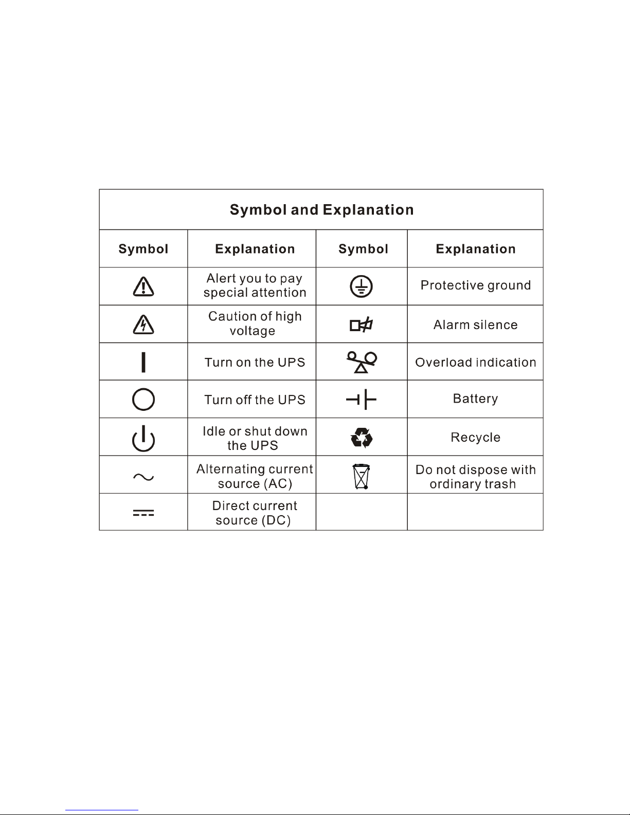
2. Description of commonly used symbols
Some or all of the following symbols may be used in this manual. It is
advisable to familiarize yourself with them and understand their
meaning:
Page 9
6
3. Introduction
This On-Line-Series is an uninterruptible power supply incorporating
double-converter technology. It provides perfect protection specifically
for Novell, Windows NT and UNIX servers.
The double-converter principle eliminates all mains power disturbances.
A rectifier converts the alternating current from the socket outlet to direct
current. This direct current charges the batteries and powers the
inverter. On the basis of this DC voltage, the inverter generates a
sinusoidal AC voltage, which permanently supplies the loads.
Computers and periphery are thus powered entirely by the mains
voltage. In the event of power failure, the maintenance-free batteries
power the inverter.
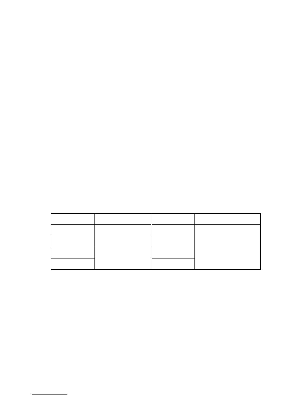
This manual covers the UPS listed as follows. Please confirm whether it
is the model you intend to purchase by performing a visual inspection of
the Model No. on the rear panel of the UPS.
“S” Model: Extended backup time
Model No. Type Model No. Type
1K 1KS
2K 2KS
3K 3KS
6K
Standard
6KS
Extended backup
time
Page 10
7
4. Panel description
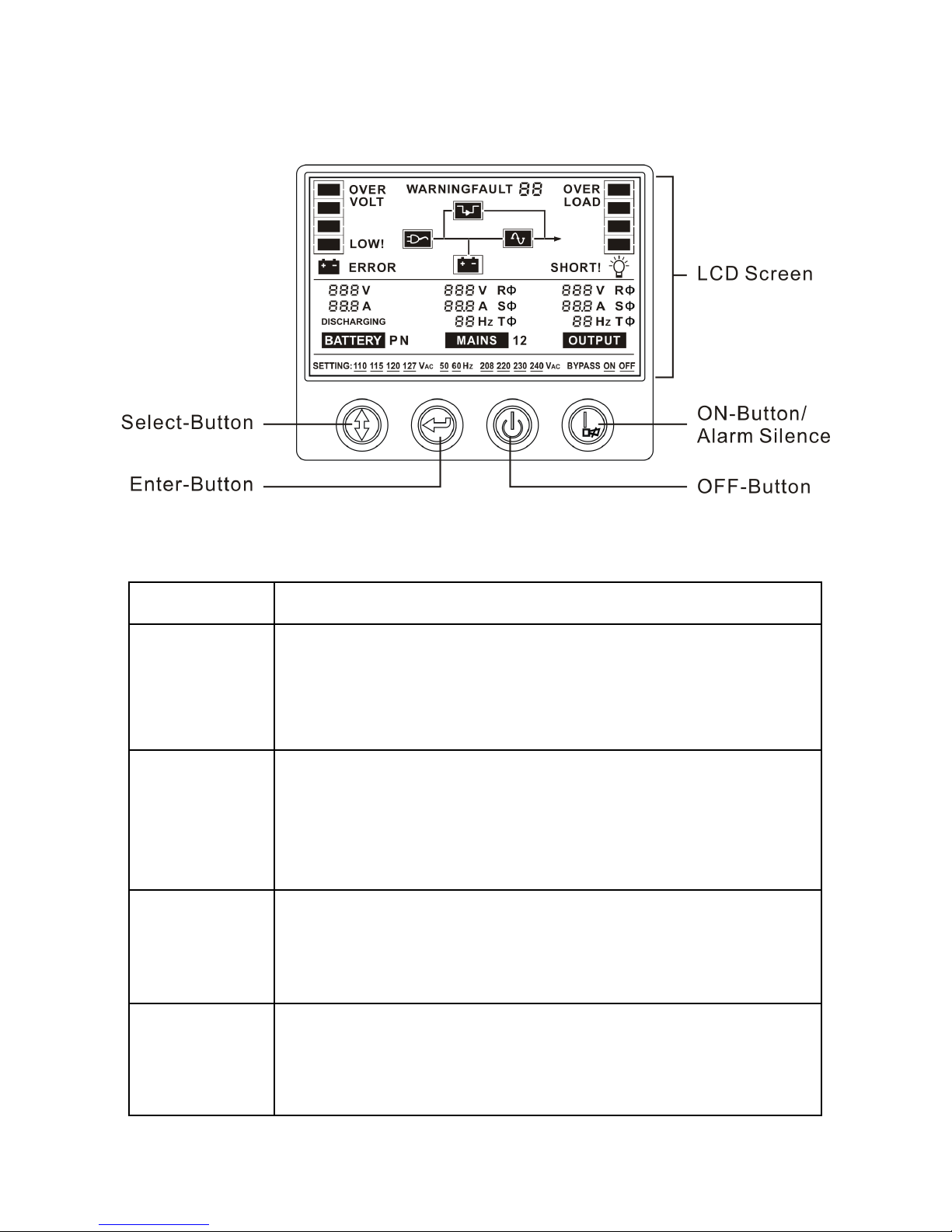
The Display Panel
Switch Function
ON-Button
Turn on UPS system:
By pressing the “ON” button the UPS system is turned on.
Deactivate acoustic alarm:
By pressing this Button an acoustic alarm can be deactivated.
OFF-Button
When mains power is normal, the UPS system switches to No
output or Bypass mode by pressing “OFF” button, and the
inverter is off. At this moment, if Bypass is enabled, then the
output sockets are supplied with voltage via the bypass if the
mains power is available.
Select-Button
If the UPS system is No output or Bypass mode, the output
voltage and frequency and Bypass disable/enable could be
selected by pressing Select-Button, and confirmed by pressing
Enter-Button.
Enter-Button
If the UPS system is No output or Bypass mode, the output
voltage and frequency and Bypass disable/enable could be
selected by pressing Select-Button, and confirmed by pressing
Enter-Button.
Page 11
8
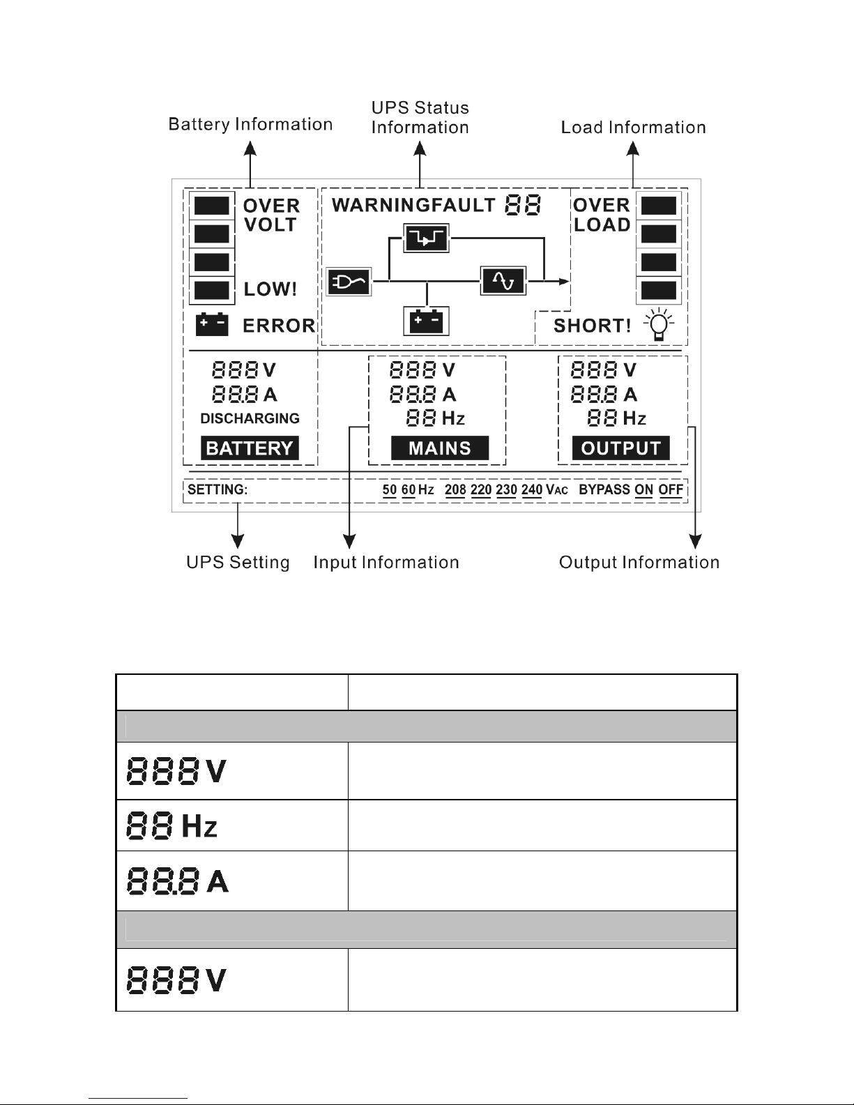
The LCD Display
Display Function
Input Information
Indicates the input Line voltage value, which could
be displayed from 0 to 999Vac
Indicates the frequency value of input Line
voltage, which could be displayed from 0 to 99Hz
Indicates the input Line current value, which could
be displayed from 0 to 99.9A
Output Information
Indicates the UPS output voltage value, which
could be displayed from 0 to 999Vac
Page 12
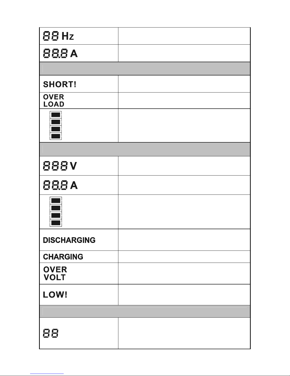
9
Indicates the frequency value of the UPS output
voltage, which could be displayed from 0 to 99Hz
Indicates the UPS output current value, which
could be displayed from 0 to 99.9A
Load Information
Indicates the load or the UPS output is short and
the UPS would shut down
Indicates the load is over the SPEC range
Indicates the load percent, and the lowest grid
represent 30% load, the two low grids represent
60% load, the three low grids represent 90% load,
all the grids represent 100% load.
Battery Information
Indicates the battery voltage value, which could
be displayed from 0 to 999Vdc
Indicates the battery current value, which could be
displayed from 0 to 99.9A
Indicates the battery capacitance percent, and
every grid represent 25% capacitance. All the
grids represent 100% capacitance.
Indicates the UPS is working in the battery mode,
and the battery is discharged for supplying the
load
Indicates the battery is being charged
Indicates the battery is over charged, and the
UPS would be switched to Battery mode
Indicates the battery is weak, and the UPS would
shut down soon
UPS status Information
Indicates some the warning or fault occur in the
UPS, fault code or warning code could be
displayed, and the codes are illuminated in detail
in the following chapter
Page 13
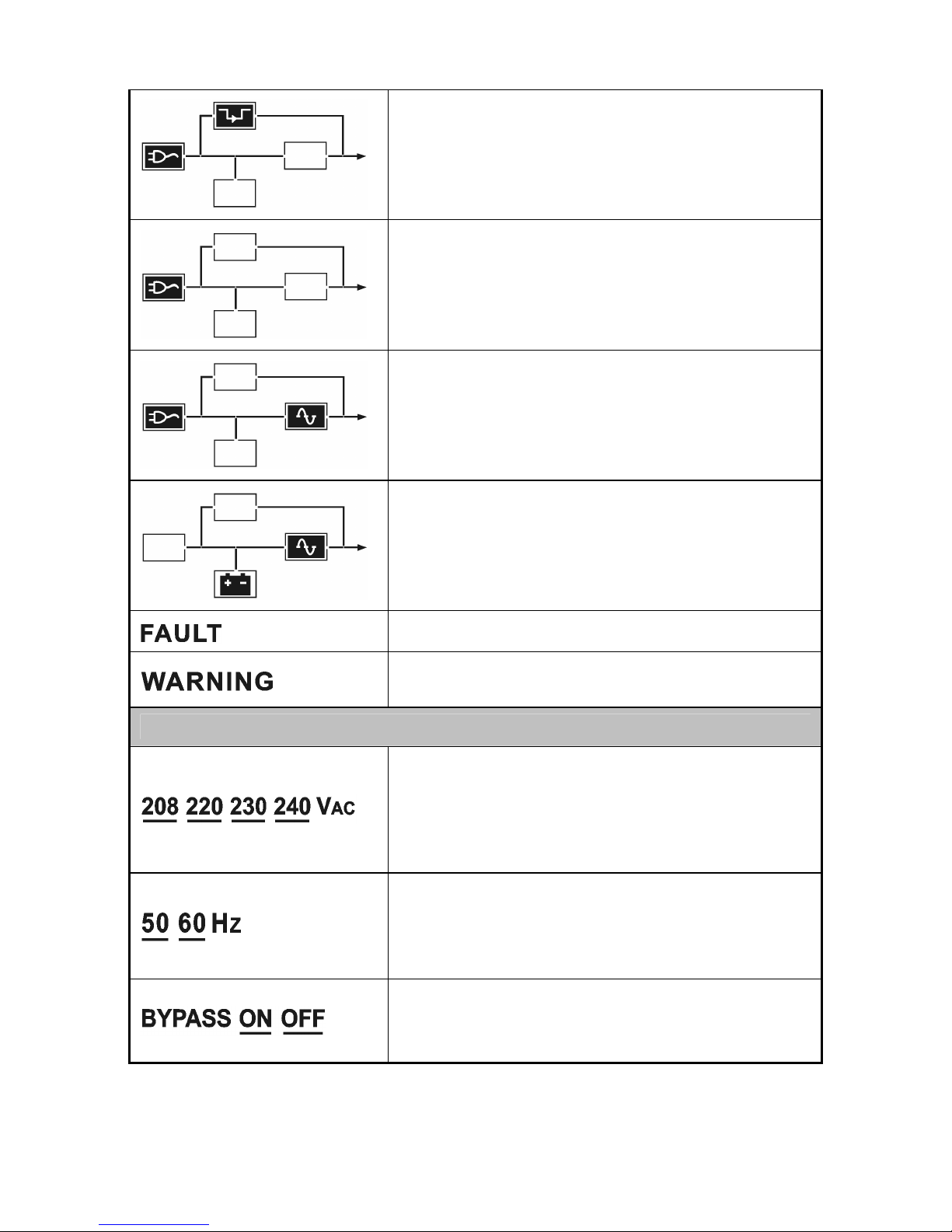
10
Indicates the UPS is working in bypass mode, the
load is directly supplied by the input power
through bypass
Indicates the UPS is working in no output mode
Indicates the UPS is working in line mode
Indicates the UPS is working in battery mode or
battery test mode
Indicates the UPS is working in fault mode
Indicates some warnings occur which need be
attention
UPS setting Information
The four value of the output voltage could be
selected when the UPS is in No output or Bypass
mode, and only one of them could be active in the
same time. Derating 10% when the output voltage
is adjusted to 208VAC
The two frequency value of the output voltage
could be selected when the UPS is in No output or
Bypass mode, and only one of them could be
active in the same time
Bypass disable or enable could be selected when
the UPS is in No output or Bypass mode, and only
one of them could be active in the same time
Page 14
11
5. Connection and operation
5.1 Inspection:
Inspect the packaging carton and its contents for damage. Please
inform the transport agency immediately should you find signs of
damage.
Please keep the packaging in a safe place for future use.
Note: Please ensure that the incoming feeder is isolated and
secured to prevent it from being switched back on again.
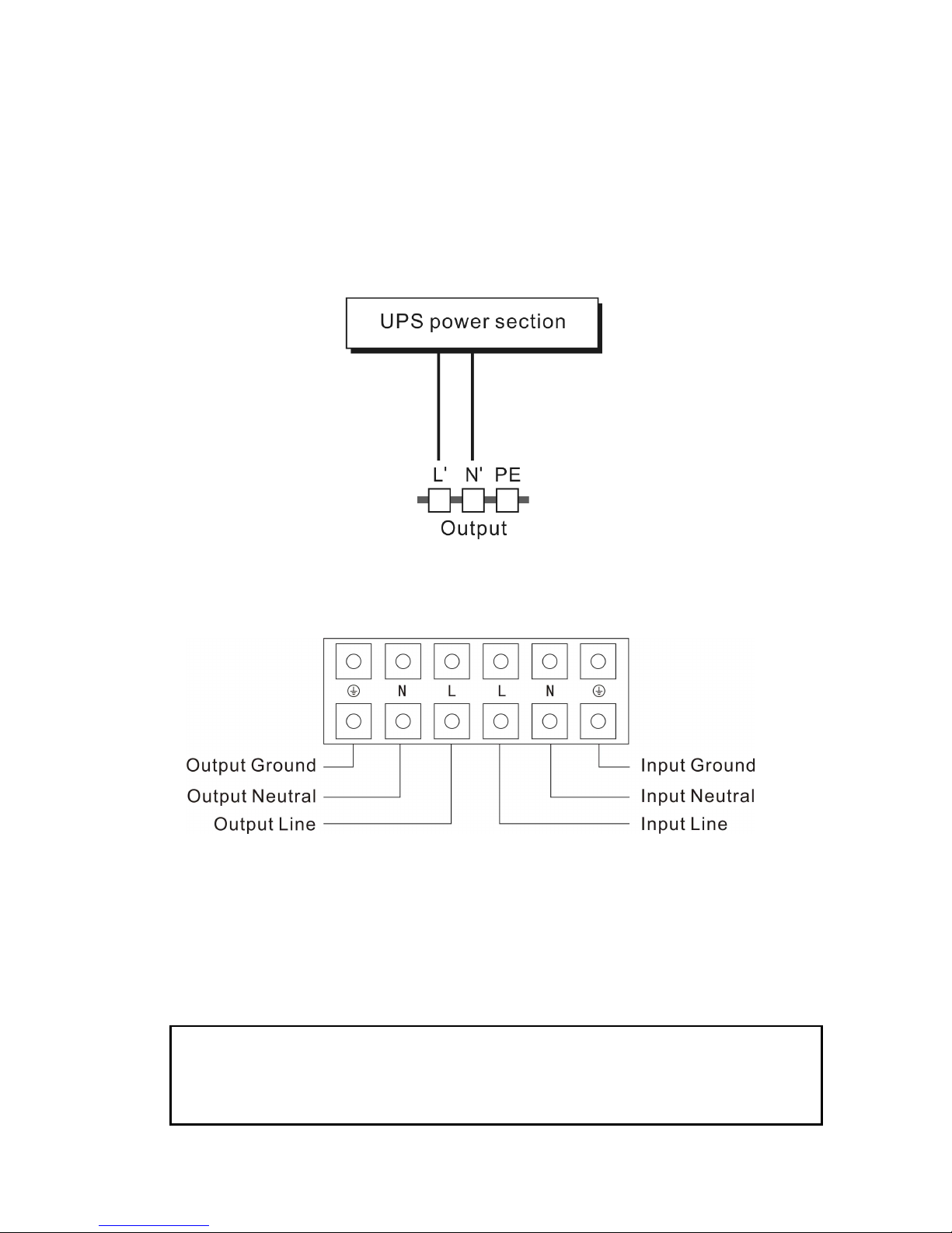
5.2 Connection:
(1) UPS Input Connection
If the UPS is connected via the power cord, please use a proper
socket with protection against electric current, and pay attention to
the capacity of the socket: over 10A for 1K(S) & 2K, over 16A for
2KS& 3K(S).
(2) UPS Output Connection
The output of 1K(S), 2K are socket-types only. Simply plug the
load power cord to the output sockets to complete connection.
Besides output sockets, 2KS, 3K/3KS and 6K/6KS have the
terminal block available for output as well.
The wiring configuration is shown as the following procedure:
The system may be installed and wired only by qualified
electricians in accordance with applicable safety regulations!
When installing the electrical wiring, please note the nominal
amperage of your incoming feeder
.
Page 15
12
a) Remove the small cover of the terminal block
b) Use AWG14 or 2.1mm
2
wires for wiring configuration
c) Upon completion of the wiring configuration, please check
whether the wires are securely affixed.
d) Put the small cover back to the rear panel.
(3) Computer Connection:
Connect your computer to the outlet sockets of the UPS system
following the above diagram.
Caution!
Do not connect equipment which would overload the UPS
system (e.g. laser printers)
Connection diagram of 2KS and 3K(S)
Terminal Block wiring diagram of 6K(S)
Page 16

13
5.3 Battery Charge:
Fully charge the batteries of the UPS system by leaving the UPS
system connected to the mains for 8 hours. You may use the UPS
system directly without charging it but the stored energy time may be
shorter than the nominal value specified.
5.4 Turn On the UPS:
(1) With utility power connecting:
Press “I” button continuously for more than 1 second to turn on the
UPS. Then the UPS will get into self-test status first. After having
finishing the self-test, the UPS will get into the inverter mode, at
this time, the LCD screen will light up and indicate the state of the
UPS.
(2) Without utility power connecting:
Even though utility power is not connected to the UPS, the UPS
still can be turned on by just simply pressing “I” button
continuously for more than 1 second. Then the UPS will get into
self-test status first. After having finishing the self-test, the UPS
will get into the inverter mode, at this time, the LCD screen will
light up and indicate the state of the UPS.
Note: The default setting for bypass mode is no output after UPS
is connecting utility power and breaker is turned on. This can be
configured by monitoring the LCD panel or firmware.
5.5 Test Function:
Test the function of the UPS system by either pressing the “On”
button or disconnecting the input of the UPS system from the power
supply.
Page 17

14
5.6 Turn Off the UPS:
(1) In Inverter Mode:
Press “OFF” button continuously for more than 1 second to turn off
the UPS. Then the UPS will get into self-test status first. After
having finished the self-test, the UPS will get into no output or
bypass mode. At this time, the UPS might has output if bypass is
enabled. Disconnect the utility power to turn off the output.
(2) In Battery Mode:
Press “OFF” button continuously for more than 1 second to turn off
the UPS. Then the UPS will get into self-test status first. After
having finished the self-test, the UPS will be turned off completely.
NOTE::::In emergency situation, the UPS can be shutdown by
taking off the EPO cover on the rear panel of the UPS. When
you want to turn on the UPS, you should restore the cover
firstly.
5.7 Audible Alarm Mute Function:
If the alarm is too annoying in battery mode, you may press “ON”
button continuously for more than 1 second to clear it. Moreover, the
alarm will be enabled when the battery is low to remind you to
shutdown the load soon.
5.8 Operation Procedure of External Battery for Long
Backup time Model (“S” Model)
The units with CE markings—
1) Use the battery pack with voltage: 36VDC for 1KS (6 pcs of 12V
batteries paralleled as 2 teams), 96VDC for 2KS/ 3KS (8 pcs of
12V batteries) 240VDC for 6KS(20pcs of 12V batteries).
Connection of batteries more than or less than required will cause
abnormality.
Page 18

15
2) One end of the external battery cord is a plug for connecting the
UPS and the other end has a plug for connecting the user battery
cabinet.
3) Do not connect the UPS to any load yet. Then, connect the power
cord of the UPS to supply utility power to the UPS to make the
UPS operate in utility power mode.
4) Connect the plug of the external battery cord to the external battery
socket on the rear panel of the UPS to complete the connection
procedure and the UPS will start to charge the battery pack.
5) The red wire is connected to the "+" terminal of the battery. The
black wire is connected to the "-" terminal of the battery. (Note: the
green/yellow wire is grounded for protection purpose.)
The Caution!
The output sockets of the UPS system may still be electrically live
even if the power supply system has been disconnected or the
Bypass switch is on “OFF” position.
Page 19
16
6. Operating mode for all models
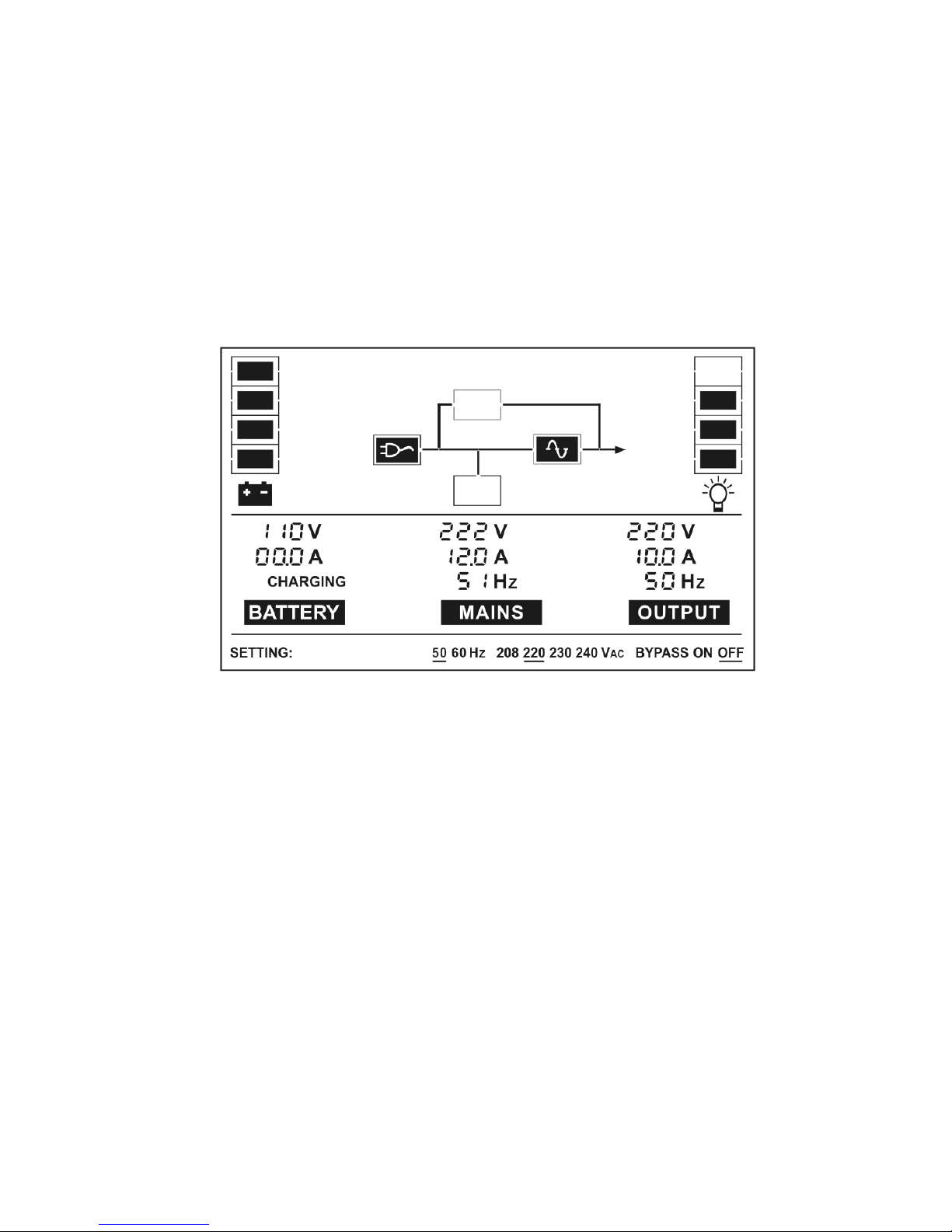
6.1 Line mode
The LCD display in Line mode is shown in the following diagram. The
information about the utility power, the battery, the UPS output and
the load could be displayed.
If output overloaded, the load percent is shown and alarm will keep
twice every second. You should get rid of some unnecessary loads
one by one to decrease the loads connected to the UPS less than
90% of its nominal power capacity.
Note: Please follow the following steps to connect the generator:
● Activate the generator and wait until the operation is stable before
supplying power of the generator to the UPS (be sure that the UPS
is in idle mode). Then turn on the UPS according to the start-up
procedure. After the UPS is turned on, then the loads can be
connected to the UPS one by one.
●
The power capacity of the AC generator should be at least twice of
the UPS capacity.
■■■■ The
Line
mode
Page 20
17
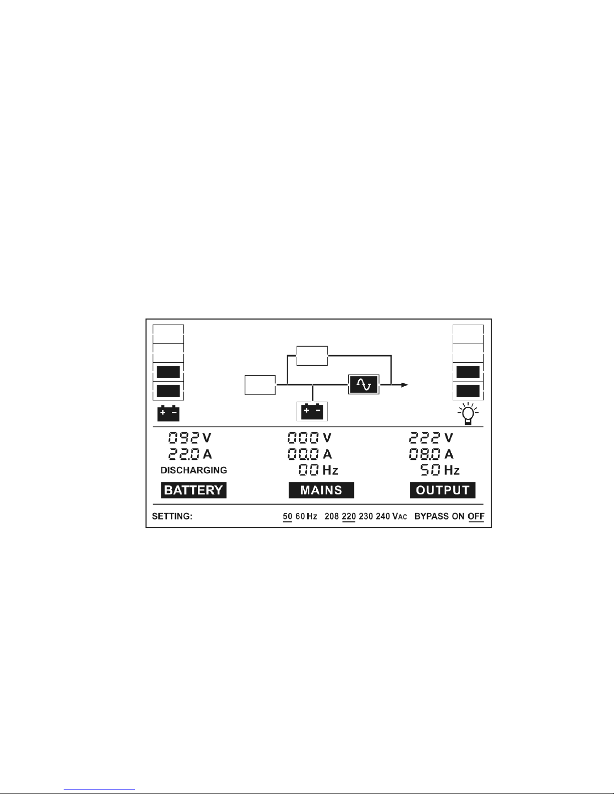
6.2 Battery mode
The LCD display in battery mode is shown in the following diagram.
The information about the utility power, the battery, the UPS output
and the load could be displayed.
(1) When the UPS is running in battery mode, the buzzer beeps once
every 4 seconds. If the “ON” button on the front panel is pressed
for more than 1 second again, the buzzer will stop beeping (in
silence mode). Press the “ON” button once again for more than 1
second to resume the alarm function.
(2) The display is the same in battery test mode.
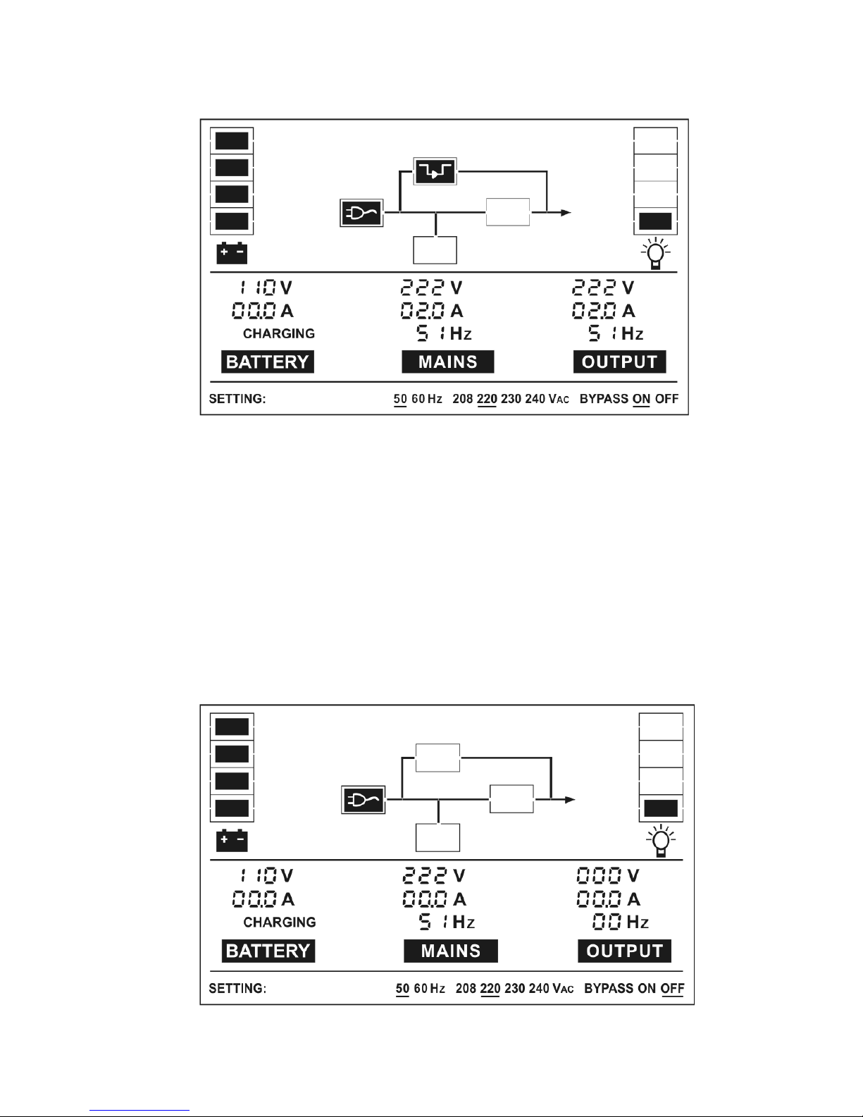
6.3 Bypass mode
The LCD display in bypass mode is shown in the following diagram.
The information about the utility power, the battery, the UPS output
and the load could be displayed. The UPS will beep once every 2
minutes in bypass mode.
■■■■ The Battery mode
Page 21
18
The UPS does not have the backup function when it is in bypass
mode. The power used by the load is supplied from the utility power
via internal filter.
6.4 NO output mode
The LCD display in no output mode is shown in the following diagram.
The information about the utility power, the battery, the UPS output
and the load could be displayed.
■■■■
The B
ypass mode
■■■■
The NO output
mode
Page 22

19
6.5 Abnormal mode
In abnormal mode such as Bus fault etc., the corresponding fault code
would be shown to indicate the operating mode of the UPS. And some
warning words could also be shown, for example “short!” would be
shown when the load or the UPS output is short and the UPS is in
inverter fault mode.
Page 23

20
7. Setting by LCD module
The output voltage and frequency and bypass state could be set directly
through LCD module. The output voltage could be set to 208V, 220V,
230V and 240V. The output frequency could be set to 50Hz and 60Hz.
The bypass state could be set to enable and disable. But all the settings
could only be done when the UPS is in bypass or no output mode.
In bypass or no output mode, pressing the “Select” button on the LCD
panel for more than one second, a flickering black line would be shown
under “208V” on the screen. And if pressing the “Select” button
continuously again, the flickering black line would move to “220V”, next to
“230V”, “240V”, “50Hz”, “60Hz”, “Bypass Disable”, “Bypass Enable” in turn.
And if pressing the “Enter” button for more than one second at this time,
the flickering black line would turn to flickerless and the output voltage or
frequency or bypass state setting would be modified to the selected value.
And if no any pressing on the “Select” or “Enter” button lasting for more
than ten seconds, the flickering black line would disappear.
The only one voltage value could be selected in “208V”, “220V”, “230V”,
“240V” at any time. The only one frequency value could be selected in
“50Hz”, “60Hz” at any time. And the output voltage and frequency would
be changed to the corresponding value after the right values are selected
on the LCD panel and the UPS is turn on by pressing the “ON” Button.
The UPS would turn to bypass mode in several seconds after “Bypass
Enable” is selected, and turn to no output mode in several seconds after
“Bypass Disable” is selected.
Page 24
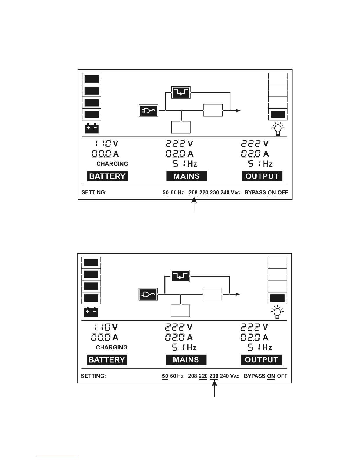
21
■■■■ Here is a example for changing the output voltage from 220Vac to
230Vac through the LCD panel.
Step 1:
One flickering black line would appear under “208Vac” after
pressing the “Select” button.
Step 2:
The flickering line would move to “230Vac” after pressing the
“Select” button two times again.
Page 25
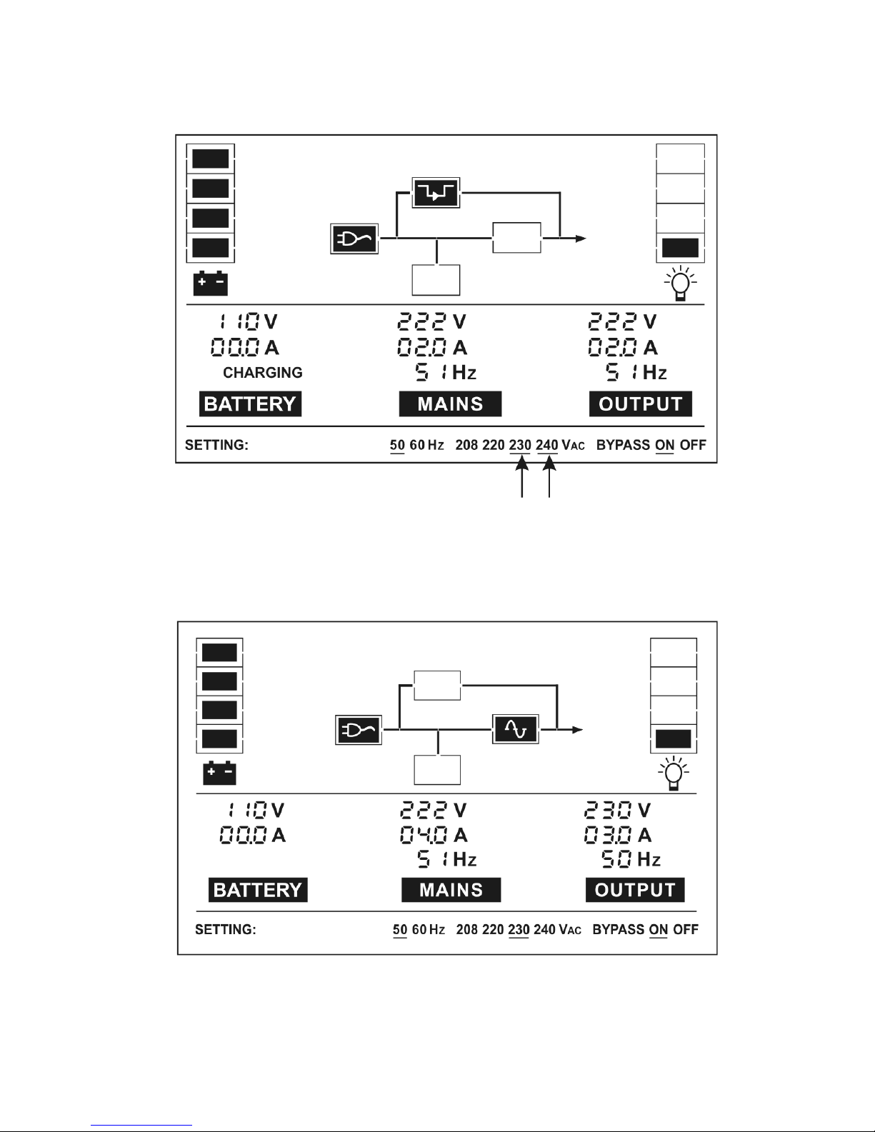
22
Step 3:
The line under “230Vac” would turn to flickerless after
pressing the “Enter” button, and the flickering line would
move to the next “240Vac”.
Step 4:
The output voltage would be 230Vac after the UPS is turned
on.
Page 26

23
8. Trouble shooting
If the UPS is working abnormally, the warning or fault codes would be
shown to indicate the status of UPS. Even several warnings could appear
in the same time, and the warning codes would be shown circularly. Once
one fault is come forth, then all previous warnings would not be shown
again but only the fault code is presented.
Warning and Fault Code Warning and Fault Code
Bus fault 05 Site fail warning 09
Inverter fault 06 Fan fail warning 10
Overload fault 07 Bat over warning 11
Over temperature fault 08 Bat weak warning 12
Charger fail warning 13
If the UPS system does not operate correctly, please attempt to solve the
problem using the table below.
Problem Possible cause Remedy
No indication, no
warning tone even
though system is
connected to mains
power supply
No input voltage
Check building wiring socket
outlet and input cable.
The status indicates the
UPS is in no output or
bypass mode, even
though the power
supply is available
Inverter not
switched on
Press “ON” button and turn on the
UPS
Page 27

24
The status indicates the
UPS is in battery mode,
and audible alarm
sounding every 1 beep
in every 4 seconds
Mains power
supply has failed
or input power
and/or frequency
are out of
tolerance
Switching to battery mode
automatically. When audible
alarm sounding every second,
battery is almost empty.
Check input power source and
inform dealer if necessary
Warning code is shown
as 09
Phase and neutral
conductor at input
of UPS system
are reversed
Rotate mains power socket by
180° or connect UPS system.
Warning code is shown
as 13, warning tone
once a second
Charger or
Batteries
damaged
Notify dealer!!
Warning code is shown
as 10
Fan is locked or
not working
Check fans and notify dealer!!
Fault code is shown as
07, warning tone once
a second
Overload
Remove loads of UPS output and
restart.
Fault code is shown as
05 or 06 or 08,
permanent warning
tone
UPS fault Notify dealer!!
Emergency supply
period shorter than
nominal value
Batteries not fully
charged / batteries
defect
Charge the batteries for at least
1 ~ 2 hours and then check
capacity. If the problem still
persists, consult your dealer.
Please have the following information at hand before calling the
After-Sales Service Department:
1. Model number, serial number
2. Date on which the problem occurred
3. Detailed description of the problem
Page 28

25
9. Maintenance
9.1 Operation
The UPS system contains no user-serviceable parts. If the battery
service life (3~5 years at 25°C ambient temperature) has been
exceeded, the batteries must be replaced. In this case please contact
your dealer.
9.2 Storage
If the batteries are stored in temperate climatic zones, they should be
charged every three months for 1~2 hours. You should shorten the
charging intervals to two months at locations subject to high
temperatures.
Page 29

26
10. Technical data
10.1 Electrical specifications
INPUT
Model No. 1K(S) 2K 2KS 3K(S) 6K
6KS
Phase
Single
Frequency (46~54)/(56~64) Hz
Current(A) 7A 9A 12A 16A 32A
50A
OUTPUT
Model No. 1K(S) 2K(S) 3K(S) 6K(S)
Power rating 1kVA/0.7kW 2kVA/1.4kW 3kVA/2.1kW
6KVA/4.2KW
Voltage
208/220/230/240×(1 士 2%)VAC
Frequency
50/60×(1±0.2)Hz (Battery mode)
Wave form sinusoidal
Derating 10% when the output voltage is adjusted to 208VAC
BATTERIES
Model No. 1K 2K 3K 6K
Number and type
3×12V 7.2Ah 8×12V 7.2Ah 8×12V 7.2Ah 20×12V 7.2Ah
10.2 Operating Environment
Ambient Temperature 0 oC to 40 oC
Operating humidity < 95%
Altitude < 1000m
Storage temperature 0 oC ~ 40 oC
Page 30

27
10.3 Dimensions and weights
Model No.
Dimensions W×D×H
(mm)
Net Weight
(kg)
1K
482.6×470×88
16.3
1KS
482.6×470×88
9.1
Battery Pack 36V
482.6×470×88
17.5
2K
482.6×470×88
11.2
2KS
482.6×470×88
12.3
3K
482.6×470×88
11.2
3KS
482.6×470×88
12.3
Battery Pack 96V
482.6×470×88
22.5
6K
608×438×130
20
6KS
608×438×130
23.4
Battery Pack 240V
608×438×130
64.2
Page 31
28
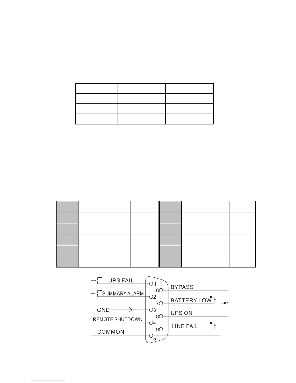
11. Communication port
11.1 RS232 Interface
The following is the pin assignment and description of DB-9
connector.
Pin # Description I/O
2 TXD Output
3 RXD Input
5 GND Input
11.2 AS400 Interface (Option)
Except for the communication protocol as mentioned above, this
series UPS has AS400 card (an optional accessory) for AS400
communication protocol. Please contact your local distributor for
details. The following is the pin assignment and description of DB-9
connector in AS400 card.
Pin # Description I/O Pin # Description I/O
1 UPS Fail Output 6 Bypass Output
2 Summary Alarm Output 7 Battery Low Output
3 GND Input 8 UPS ON Output
4 Remote Shutdown
Input 9 Line Loss Output
5 Common Input
DB-9 Interface of AS400 communication protocol
Page 32
29
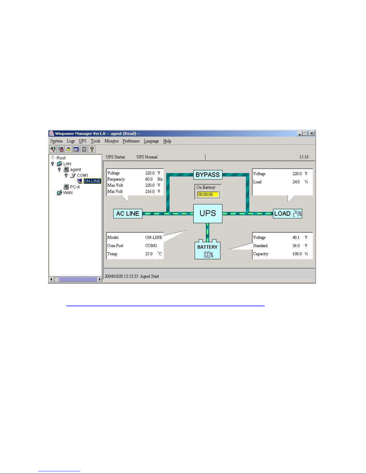
12. Software for all models
Free Software Download – WinPower
WinPower is a brand new UPS monitoring software, which provides
user-friendly interface to monitor and control your UPS. This unique
software provides safely auto shutdown for multi-computer systems while
power failure. With this software, users can monitor and control any UPS
on the same LAN no matter how far from the UPSs.
Installation procedure:
1. Go to the website:
http://www.ups-software-download.com/winpower.htm
2. Choose the operation system you need and follow the instruction
described on the website to download the software.
3. When downloading all required files from the internet, enter the serial
No: 511C1-01220-0100-478DF2A to install the software.
When your computer restarts, the WinPower software will appear as a
green plug icon located in the system tray, near the clock.
Page 33
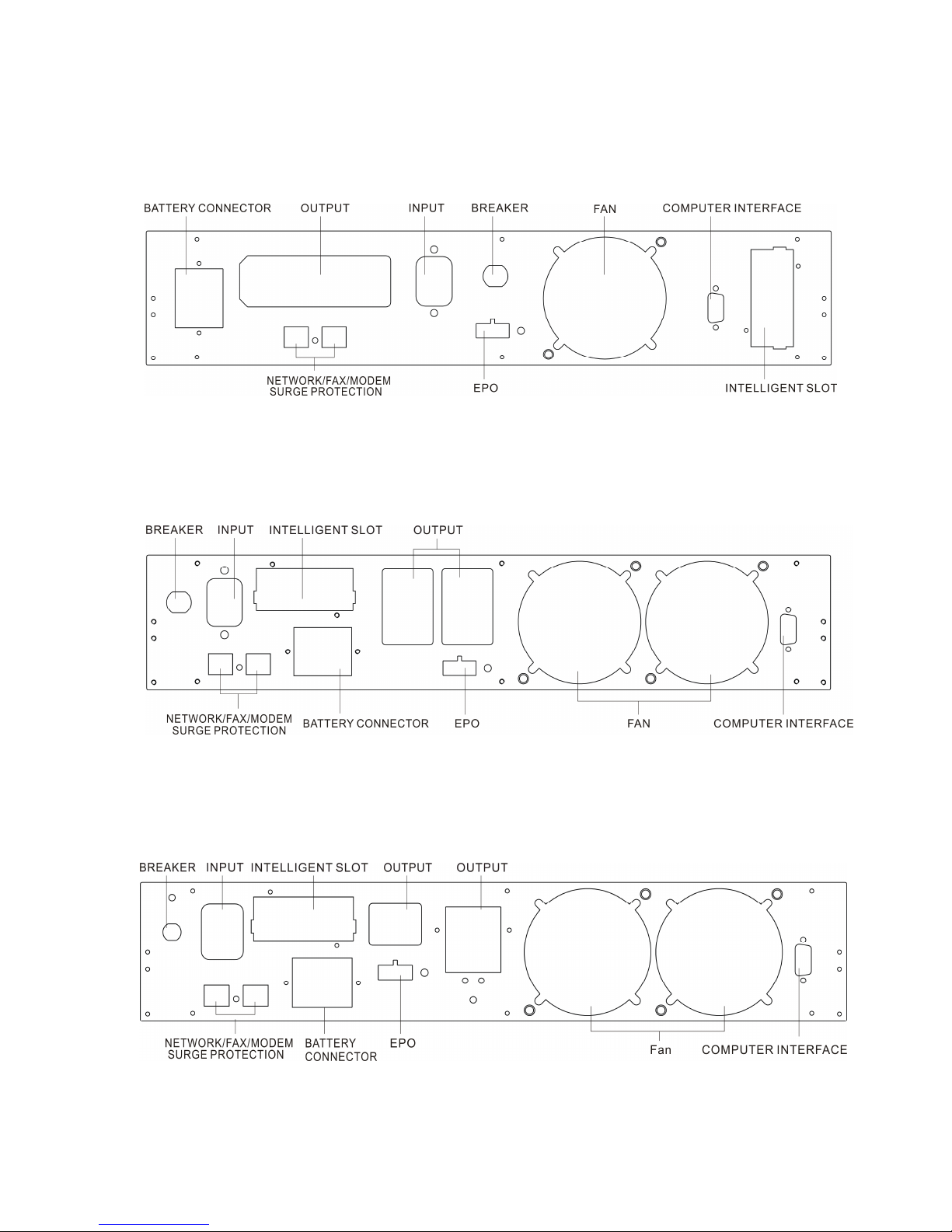
30
Appendix
Back View of 1K(S)
Back View of 2K
Back View of 2KS/3K(S)
Page 34
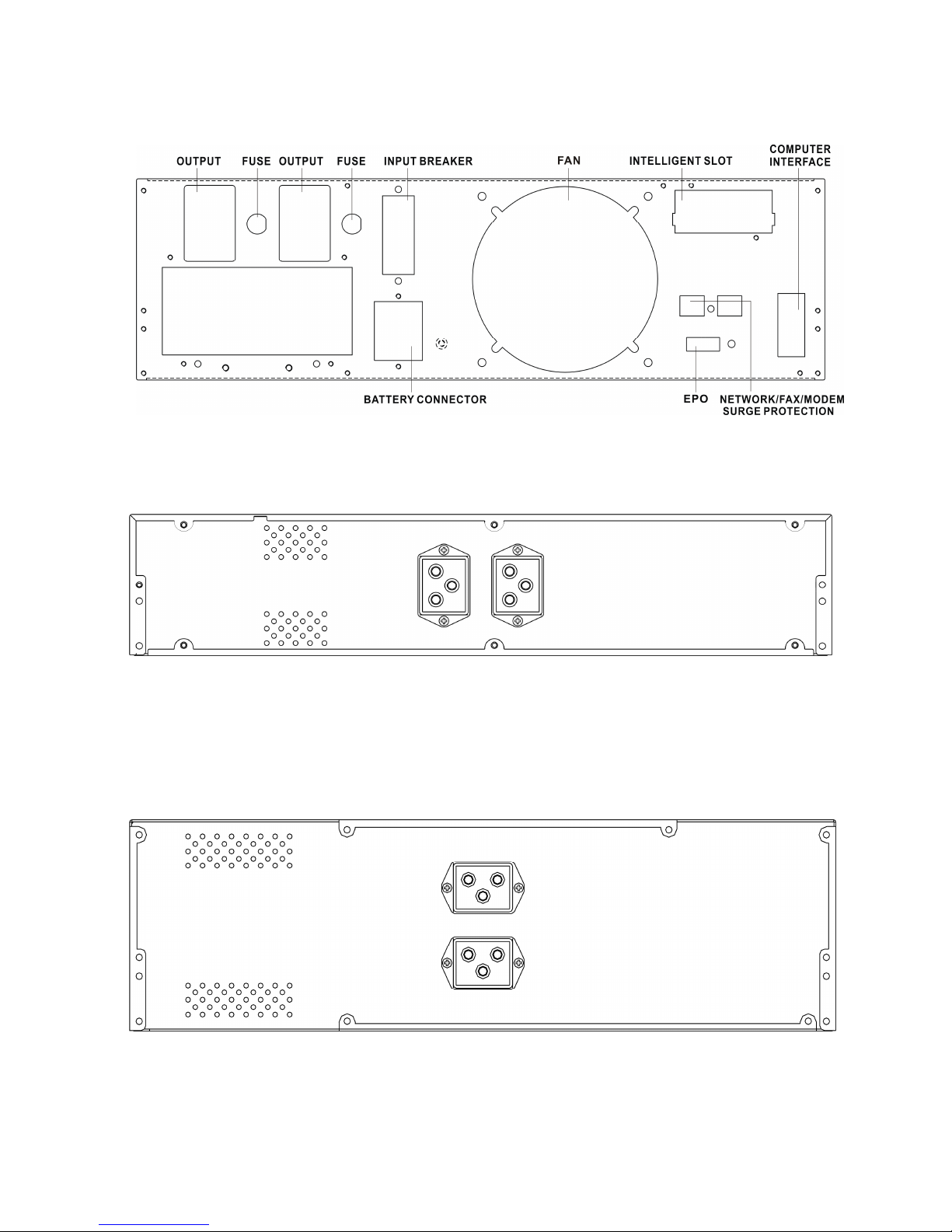
31
Back View of 6K(S)
Battery pack for 1-3KS
Battery pack for 6KS
Page 35

32
614-00652-01
Page 36
33
MANUALE
DELL’UTENTE
Modelli AP160LCD
1~6KVA
Gruppo di continuità (UPS)
Page 37
34
1. Istruzioni relative alla sicurezza e alla
EMC
(Compatibilità Elettro Magnetica
)
Leggere con attenzione il manuale dell’utente e le
istruzioni relative alla sicurezza prima di installare o
utilizzare l’unità!
1.1 Installazione
★ Si può verificare un fenomeno di condensa nel caso in cui l'UPS
venga spostato da un ambiente operativo freddo a uno caldo.
L’UPS deve essere assolutamente asciutto prima di essere
installato. Lasciare trascorrere un tempo di acclimatazione di
almeno due ore.
★ Non installare l’UPS vicino all’acqua o in ambienti umidi.
★ Non installare l’UPS in luoghi dove potrebbe essere esposto alla
luce diretta del sole o vicino a fonti di calore.
★ Nel posizionare l’UPS, porre attenzione a non ostruirne le prese
d’aria.
★ Non collegare alla presa d’uscita dell’UPS dispositivi o
apparecchiature che potrebbero sovraccaricare l'UPS (es.
stampanti laser ecc.).
★ Sistemare i cavi in modo che non possano venir calpestati o vi si
possa inciampare.
★ Le prese di corrente e i connettori delle batterie sono collegati a
terra dal cavo di alimentazione; inserire il cavo d’alimentazione
nella presa elettrica prima di usare l’UPS.
★ Collegare l’UPS solo a una presa sicura dotata di messa a terra.
★ La presa di rete domestica (presa sicura) deve essere facilmente
accessibile e vicina all’UPS.
Page 38

35
★ L’unità va installata da un tecnico.
★ Accertarsi che la connessione a terra sia affidabile
★ Durante l’installazione di questo dispositivo, la somma della
corrente di dispersione dell’UPS e dei carichi allacciati non deve
superare i 3,5mA.
1.2 Utilizzo
★ Non scollegare il cavo di alimentazione dell’UPS o la presa di
rete domestica (presa sicura dotata di messa a terra) durante
l’utilizzo: ciò interromperebbe il collegamento a terra dell’UPS e
di tutti i carichi allacciati.
★ L’UPS dispone di una propria sorgente interna di corrente
(batterie). Esiste il rischio di scossa elettrica ove si tocchino le
prese d’uscita dell’UPS o la morsettiera d’uscita anche se l’UPS
non è connesso alla presa d’installazione domestica.
★ Per scollegare completamente l’UPS, premere innanzitutto il
pulsante di Standby e poi sconnettere il cavo di alimentazione.
★ Assicurarsi che nessun liquido e nessun corpo estraneo penetri
all’interno dell’UPS.
★ L’UPS può essere utilizzato da chiunque, anche se privo di
esperienza precedente.
1.3 Manutenzione, riparazione e guasti
★ L’UPS funziona con tensioni pericolose. Le riparazioni possono
essere effettuate solo da personale di manutenzione qualificato.
★ Attenzione: pericolo di folgorazione. Anche dopo avere scollegato
l’unita dalla rete di alimentazione (presa di rete domestica), i
componenti all’interno dell’UPS rimangono connessi alla batteria
e sono pertanto potenzialmente pericolosi.
★ Prima di effettuare qualsiasi tipo di riparazione e/o manutenzione,
scollegare le batterie. Verificare che non sia presente tensione e
Page 39

36
che non ci sia un voltaggio pericoloso nel condensatore o nei
terminali del condensatore sul BUS.
★ Le batterie devono essere sostituite solo da personale qualificato.
★ Attenzione - pericolo di folgorazione. Il circuito della batteria non
è isolato dalla tensione in entrata. Possono essere presenti
voltaggi pericolosi tra i terminali della batteria e la messa a terra.
Verificare che non ci sia presenza di tensione prima di effettuare
riparazioni!
Le batterie presentano un’elevata corrente di cortocircuito e
possono causare scosse. Adottare tutte le misure
precauzionali specificate qui di seguito e tutti gli altri
provvedimenti necessari nel caso in cui si lavori con delle
batterie:
-non indossare gioielli, orologi da polso, anelli e altri oggetti
metallici.
-servirsi solo di attrezzi con impugnature e manici isolati.
★ Quando occorre, rimpiazzare le batterie con lo stesso numero e
lo stesso tipo di esemplari.
★ Non gettare le batterie nel fuoco per evitare il rischio di
esplosioni.
★ Non aprire né distruggere le batterie. L’elettrolito che ne fuoriesce
può causare danni alla pelle e agli occhi e può essere tossico.
★ Sostituire il fusibile solo con un altro fusibile dello stesso tipo e
dello stesso amperaggio per evitare rischi di incendio.
★ Non smontare l’UPS. Solo il personale qualificato addetto alla
manutenzione è autorizzato a effettuare tale operazione.
1.4 Trasporto
★ Trasportare l’UPS solo nell’imballaggio originale (per proteggerlo
da urti e impatti).
Page 40

37
1.5 Stoccaggio
★ L’UPS deve essere stoccato in un locale aerato e asciutto.
1.6 Standard
* Sicurezza
IEC/EN 62040-1-1
* EMI
Emissioni condotte......................................:IEC/EN 62040-2 Categoria C3
Emissioni radiate.........................................:IEC/EN 62040-2 Categoria C3
*EMS
ESD...............................................................:IEC/EN 61000-4-2 Level 4
RS..................................................................:IEC/EN 61000-4-3 Level 3
EFT............................................................... :IEC/EN 61000-4-4 Level 4
SURGE........................................................ :IEC/EN 61000-4-5 Level 4
CS................................................................ :IEC/EN 61000-4-6 Level 3
Campi elettromagnetici della frequenza
di rete........................................................... :IEC/EN 61000-4-8
Level 3
Segnali a bassa frequenza............................:IEC/EN 61000-2-2
Attenzione: Questo prodotto è destinato all’uso commerciale e industriale in
secondo ambiente – per evitare disturbi potrebbero rendersi necessarie
restrizioni all’istallazione o misure supplementari.
Page 41
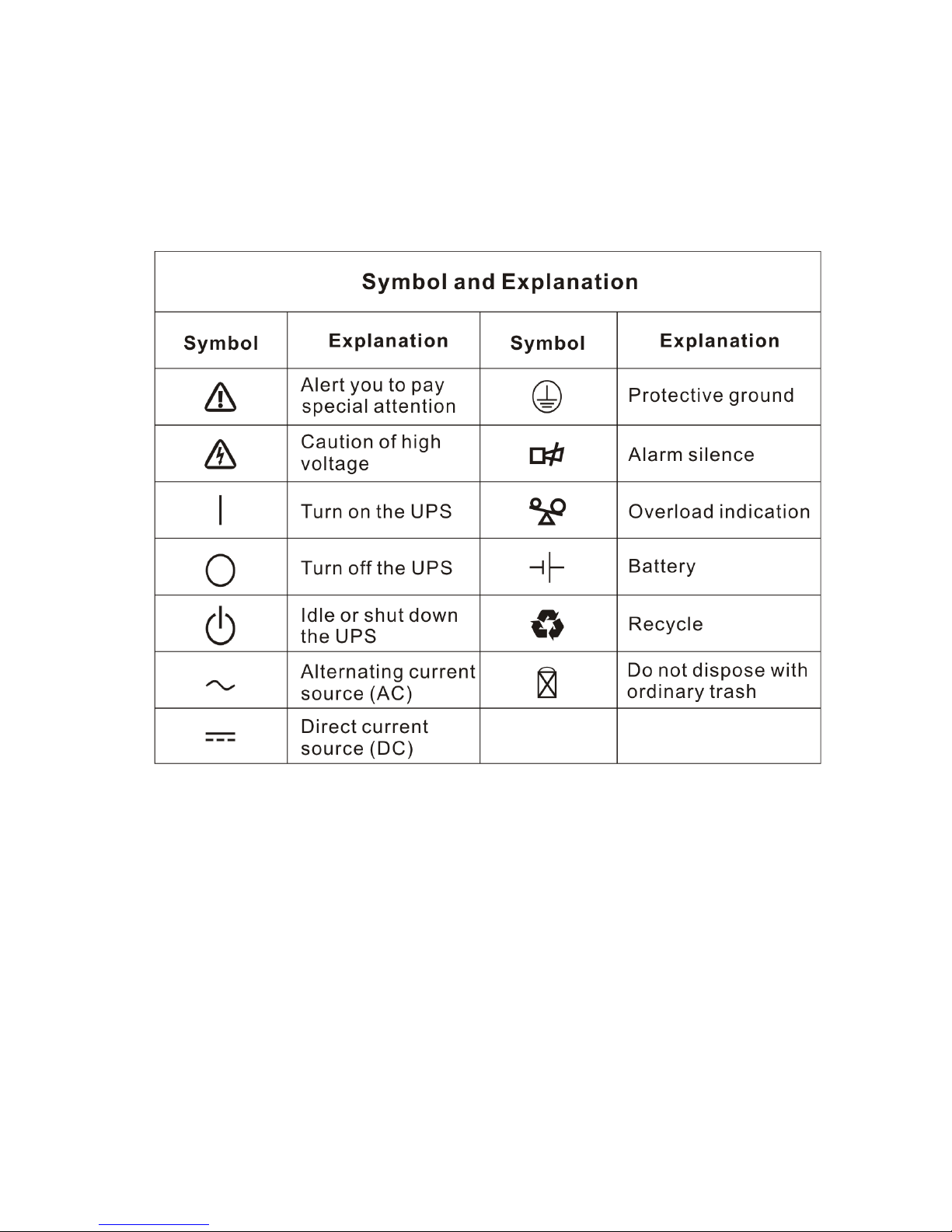
38
2. Descrizione dei simboli di uso comune
I simboli seguenti si possono incontrare, tutti o in parte, nel presente
manuale. È consigliabile imparare a conoscerli e capirne il significato:
Symbol and Explanation Simbolo e spiegazione
Alert you to pay special attention Prestare particolare attenzione
Caution of high voltage Rischio di folgorazione
Turn on the UPS Accensione UPS
Turn off the UPS Spegnimento UPS
Idle or shut down the UPS Spegnimento o disattivazione UPS
Alternating current source Presa corrente alternata (AC)
Direct current source Presa corrente continua (DC)
Protective ground Terra di protezione
Alarm silente Tacitazione allarme acustico
Overload indication Indicazione di sovraccarico
Battery Batteria
Recycle Riciclaggio
Do not dispose with ordinary trash Non smaltire nei rifiuti ordinari
Page 42

39
3. Introduzione
Il gruppo di continuità On-Line-Series incorpora la tecnologia a doppia
conversione e offre una protezione completa in particolare per i server
Novell, Windows NT e UNIX.
Grazie al principio del doppio convertitore si eliminano tutti i disturbi
della rete di alimentazione. Un raddrizzatore trasforma in corrente
continua la corrente alternata proveniente dalla presa. La corrente
continua carica le batterie e alimenta l’inverter il quale, in base alla
tensione della corrente continua, genera una corrente alternata
sinusoidale che alimenta costantemente i carichi.
Sia i computer che le periferiche sono quindi alimentati interamente dalla
tensione di rete. In caso di interruzione della corrente, l’inverter viene
alimentato dalle batterie che non necessitano di manutenzione.
Il presente manuale fa riferimento agli UPS elencati qui di seguito.
Confermare qual è il modello che si intende acquistare controllando
visivamente il numero del modello sul pannello posteriore dell’UPS.
Modello “S”: Tempo di backup prolungato
N°Modello.
Tipo N°Modello .
Tipo
1K 1KS
2K 2KS
3K 3KS
6K
Standard
6KS
A tempo di backup
prolungato
Page 43
40
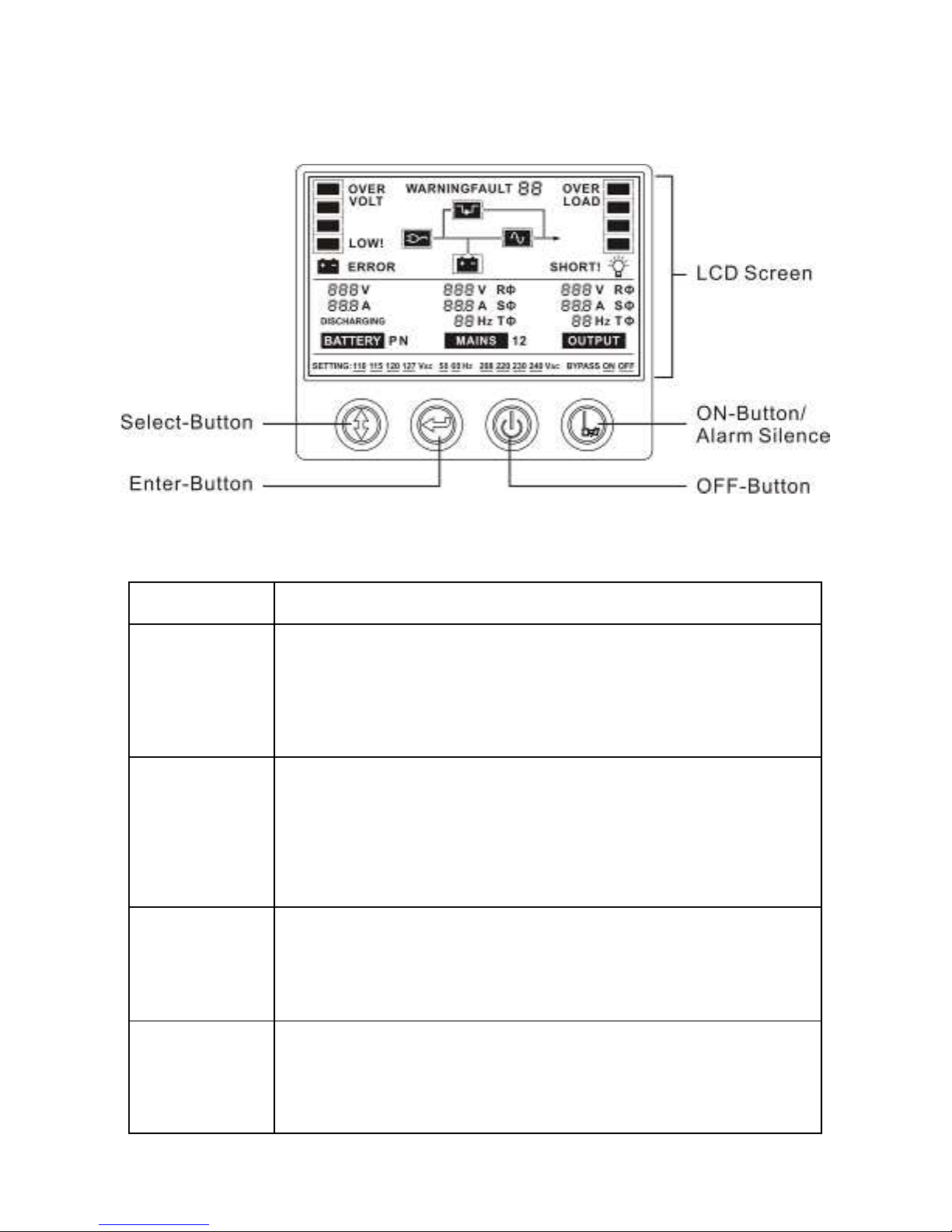
4. Descrizione del pannello
Il Pannello del Display
Pulsante Funzione
Pulsante ON
Accensione del sistema UPS:
Premendo il pulsante ON il sistema UPS si accende.
Per disattivare l’allarme acustico:
Un allarme acustico può essere disattivato premendo questo
pulsante.
Pulsante OFF
Quando l’alimentazione di rete funziona normalmente, il sistema
UPS passa alla modalità No output o alla modalità By-pass
premendo il pulsante “OFF”, e l’inverter è disattivo. Se, a
questo punto, il by-pass è abilitato, è attraverso questo che
vengono alimentate le prese d’uscita se l’alimentazione di rete è
disponibile.
Pulsante
Select
Se il sistema UPS è in modalità No output o By-pass, premendo
il pulsante Select (e confermando la scelta col tasto Enter) si
possono selezionare la tensione in uscita, la frequenza e la
possibilità di disabilitare/abilitare il by-pass.
Pulsante
Enter
Se il sistema UPS è in modalità No output o By-pass, premendo
il pulsante Select (e confermando la scelta col tasto Enter) si
possono selezionare la tensione in uscita, la frequenza e la
possibilità di disabilitare /abilitare il by-pass
Page 44
41
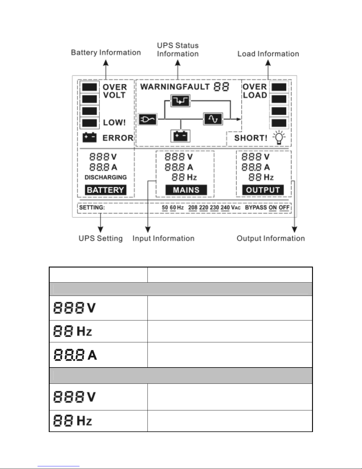
Il Display LCD
Display Function
Informazioni di input
Indica il valore del potenziale della corrente di rete
in entrata (da 0 a 999Vac).
Indica il valore di frequenza del potenziale della
corrente di rete in entrata (da 0 a 99Hz).
Indica il valore della corrente in entrata (da 0 a
99.9A).
Informazioni di Output
Indica il valore del potenziale della corrente in
uscita dell’UPS(da 0 a 999Vac).
Indica il valore di frequenza del potenziale della
corrente in uscita dell’UPS (da 0 a 99Hz).
Page 45
42
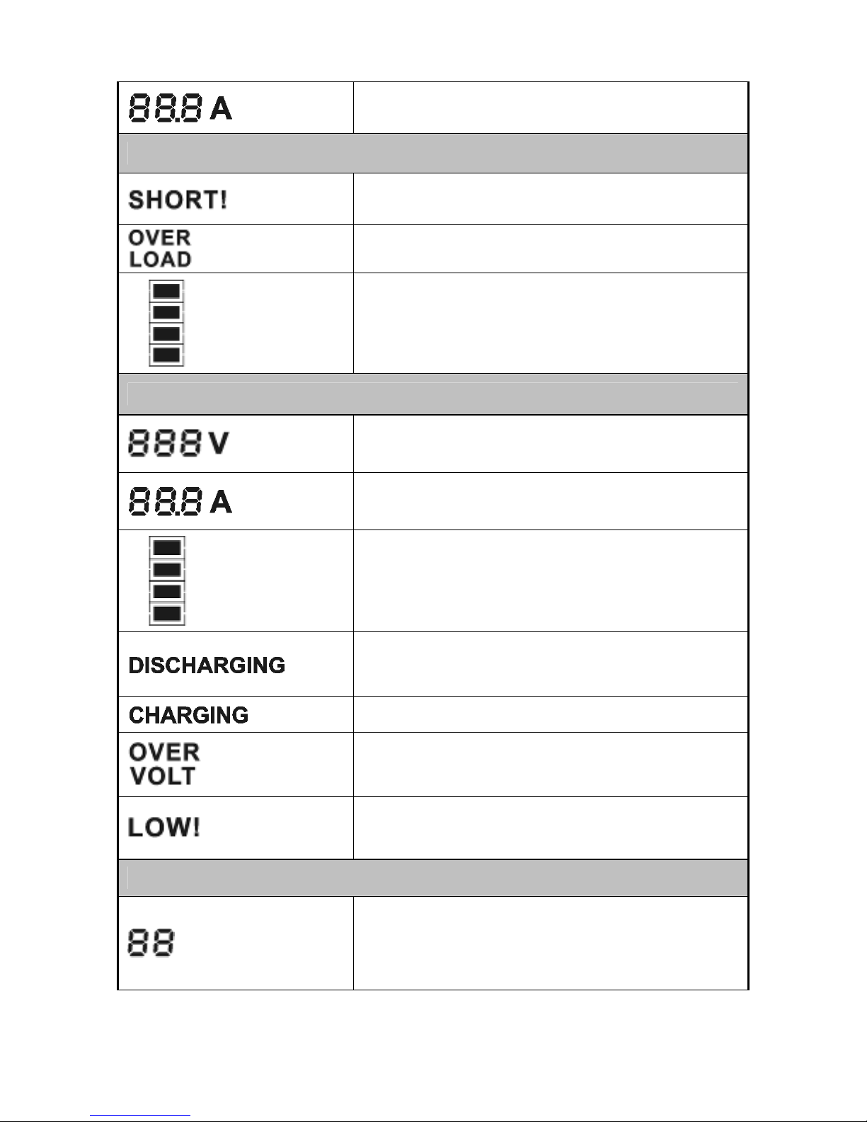
Indica il valore della corrente in uscita dell’UPS
(da 0 a 99.9A).
Informationi di carico
Indica che il carico in uscita dell’UPS è basso e
l’UPS sta per spegnersi.
Indica che il carico eccede il range di valori
indicato nelle specifiche
Indica la percentuale di carico: la tacca più bassa
indica carico del 30%, due tacche partendo dal
basso il 60%, 3 tacche il 90%, tutte le tacche il
100%.
Informationi sulla batteria
Indica il valore del potenziale della batteria (da 0 a
999Vdc)
Indica il valore della corrente di batteria (da 0 a
99.9A).
Indica la percentuale di capacità della batteria:
ogni tacca rappresenta una capacità del 25%. Se
sono visualizzate tutte le tacche, la capacità è del
100%.
Indica che l’UPS sta funzionando in modalità
batteria e che la batteria si scarica per alimentare
il carico.
Indica che la batteria si sta caricando.
Indica che la batteria è completamente carica e
che l’UPS può passare alla modalità batteria.
Indica che la carica della batteria è debole e l’UPS
si spegnerà fra poco.
Informationi sullo stato dell’UPS
Indica un allarme o un errore verificatosi nell’UPS
visualizzando il codice di allarme o di errore. I
codici sono spiegati in dettaglio nel prossimo
capitolo.
Page 46
43
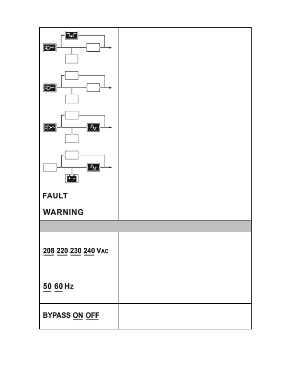
Indica che l’UPS sta funzionando in modalità
By-pass. Il carico è alimentato direttamente
dall’alimentazione di rete in entrata tramite il
by-pass.
Indica che l’UPS sta funzionando in modalità No
output.
Indica che l’UPS sta funzionando in modalità
normale di rete.
Indica che l’UPS sta funzionando in modalità
batteria o in modalità test batteria
Indica che l’UPS sta lavorando in modalità
anomala
Attenzione: indica la presenza di un allarme cui è
necessario prestare attenzione
Informazioni sull’impostazione dell’UPS
Si può selezionare il valore di voltaggio in uscita
(tra i 4 possibili) quando l’UPS è in modalità No
output o By-pass: può essere attivo soltanto un
valore alla volta. Il derating è pari al 10% quando il
voltaggio in uscita è regolato sui 208VAC.
Si può selezionare la frequenza del potenziale in
uscita (tra i 2 possibili) quando l’UPS è in modalità
No output o By-pass: può essere attivo soltanto
un valore alla volta.
Si può attivare o disattivare la modalità By-pass
quando l’UPS è in modalità No output o By-pass:
può essere attiva soltanto una delle due opzioni.
Page 47

44
5. Collegamento e utilizzo
5.1 Ispezione:
Ispezionare l’imballaggio e il suo contenuto per verificare l’assenza di
danni. Nel caso si dovessero riscontrare segni di danneggiamento,
informare immediatamente il trasportatore.
Conservare l’imballaggio in un luogo sicuro per poterlo utilizzare
successivamente.
Nota: Accertarsi che l’alimentazione di rete sia isolata e messa in
sicurezza per evitare che possa essere inserita di nuovo.
5.2 Collegamento:
(1) Collegamento UPS in entrata
Se l’UPS è connesso mediante cavo di alimentazione, usare un
connettore adeguato con opportuno isolamento e fare attenzione
per quanto riguarda la corrente che sopporta: fino a 10A per i
modelli 1K(S) & 2K, fino a 16A per i modelli 2KS& 3K(S).
(2) Collegamento UPS in uscita
I connettori in uscita dei modelli 1K(S), 2K sono esclusivamente
del tipo presa. Inserire semplicemente il cavo di alimentazione
nelle prese in uscita per completare la connessione.
Oltre alle prese in uscita, i modelli 2KS, 3K/3KS and 6K/6KS
Il sistema può essere installato e cablato solo da elettricisti
qualificati, in conformità ai vigenti regolamenti di sicurezza!
Porre attenzione alla corrente nominale della propria
fornitura elettrica quando si procede al cablaggio.
Page 48
45
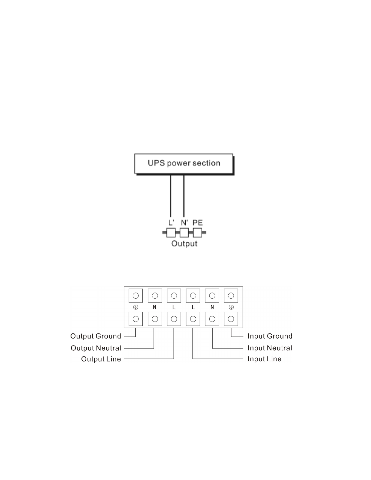
dispongono anche di morsettiera . La procedura di configurazione
del cablaggio è la seguente:
a) Rimuovere il coperchietto della morsettiera
b) Usare cavi AWG14 o da 2,1mm
2
per realizzare il cablaggio
c) Una volta completato il cablaggio, verificare che I cavi siano
assicurati saldamente.
d) Rimettere il coperchietto alla morsettiera posta sul pannello
posteriore.
(3) Collegamento del Computer:
Connettere il proprio computer alle prese in uscita del sistema
UPS secondo il diagramma sopra riportato.
Diagramma di connessione dei modelli
2KS
e
3K(S)
Diagramma della morsettiera del 6K(S)
Page 49

46
5.3 Caricamento della batteria:
Caricare completamente le batterie del sistema UPS lasciandolo
connesso alla rete di alimentazione per 8 ore. È possibile utilizzare
direttamente il sistema UPS senza caricarlo, ma il tempo di
autonomia può risultare più breve rispetto al valore nominale
specificato.
5.4 Accensione dell’UPS:
(1) Connessione in presenza di tensione di rete:
Tenere premuto il pulsante “I” per più di 1 secondo per accendere
l’UPS. L’UPS effettuerà prima di tutto il test automatico. Una volta
terminato il test automatico, l’UPS passerà alla modalità inverter e,
a questo punto, lo schermo LCD si accenderà indicando lo stato
dell’UPS.
(2) Connessione senza tensione di rete:
Anche nel caso in cui non sia presente tensione di rete, l’UPS può
essere comunque acceso tenendo semplicemente premuto per
più di 1 secondo il pulsante “I”. L’UPS effettuerà prima di tutto il
test automatico. Una volta terminato il test automatico, l’UPS
passerà alla modalità inverter e, a questo punto, lo schermo LCD
si accenderà indicando lo stato dell’UPS.
Nota: le impostazioni predefinite per la modalità By-pass
sono quelle della modalità No output una volta connesso
l’UPS alla rete elettrica e acceso l’interruttore. Queste
impostazioni possono essere configurate dal pannello LCD o
sul firmware.
Attenzione!
Non connettere dispositivi periferici che possano sovraccaricare
il sistema UPS (es. stampanti laser)
Page 50

47
5.5 Test di funzionalità:
Premere il pulsante “On” per testare la funzionalità del sistema UPS o
disconnetterlo dall’alimentazione di rete in entrata.
5.6 Spegnimento dell’UPS:
(1) In modalità inverter:
Tenere premuto il pulsante “OFF” per più di 1 secondo per
spegnere l'UPS. L’UPS effettuerà per prima cosa il test automatico.
Una volta terminato il test, l’UPS passerà alla modalità No output o
By-pass. A questo punto, nel caso sia attiva la modalità By-pass,
l’UPS può avere potenza in uscita. Sconnettere l’alimentazione di
rete per disattivare l’uscita.
(2) In modalità batteria:
Tenere premuto il pulsante “OFF” per più di 1 secondo per
spegnere l'UPS. L’UPS effettuerà per prima cosa il test automatico.
Una volta terminato il test, l’UPS si spegnerà completamente.
NOTA: In situazioni di emergenza, l’UPS può essere spento
rimuovendo il coperchio dell’’EPO sul pannello posteriore
dell'unità. Per riaccendere l'UPS occorre prima rimettere il
coperchio al suo posto.
5.7 Funzione Muto per l’allarme sonoro:
Se in modalità batteria l’allarme risulta essere troppo fastidioso, è
possibile tacitarlo tenendo premuto il pulsante “ON” per più di 1
secondo. L’allarme verrà inoltre attivato quando il livello della batteria
è basso per ricordare all'utente di effettuare lo shutdown del carico.
Page 51

48
5.8 Procedura operativa della batteria esterna per modello a
tempo di backup esteso (Modello “S”)
Le unità recanti i marchi CE —
1) Usano il gruppo batterie con i seguenti voltaggi: 36VDC per il
modello 1KS (6 batterie da 12V), 96VDC per 2KS/ 3KS (8 batterie
da 12V), 240VDC per 6KS(20 batterie da12V). Se il numero delle
batterie connesse è superiore o inferiore a quello richiesto, si
verificheranno delle anomalie.
2) Un terminale del cavo della batteria esterna è una spina per la
connessione all’UPS; l’altro terminale ha una spina per connettere
il contenitore delle batterie dell’utente.
3) Non connettere ancora l’UPS a nessun carico. Connettere quindi il
cavo di alimentazione di rete all’UPS per alimentare il sistema e
permettergli di funzionare in modalità alimentazione di rete.
4) Connettere la spina del cavo della batteria esterna alla presa per
batteria esterna situata sul pannello posteriore dell’UPS per
completare la procedura di connessione. L’UPS comincerà a
caricare il gruppo batterie
5) Il cavo rosso va connesso al polo "+" della batteria. Il cavo nero va
connesso al polo "-" della batteria. (Nota: il cavo verde/giallo è
messo a terra a scopo protettivo.)
Attenzione!
Le prese in uscita del sistema UPS possono rimanere sotto tensione
anche se l’alimentazione del sistema è stata scollegata o l’interruttore
by-pass è in posizione “OFF”.
Page 52
49
6. Modalità operative per tutti I modelli
6.1 Modalità normale
(Presenza di tensione di rete)
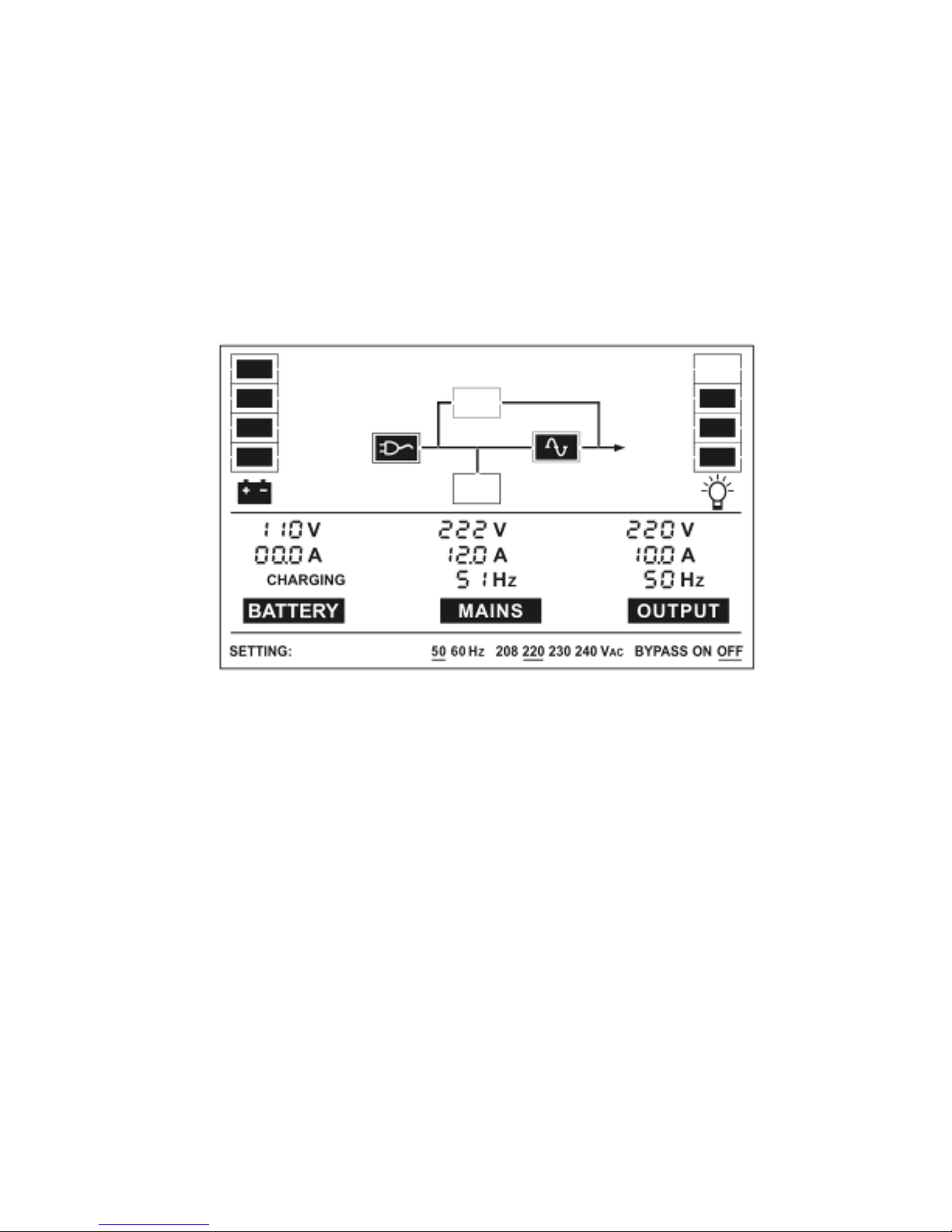
Il display LCD in modalità normale (tensione di rete presente) è
mostrato nel diagramma sottostante. Sono visualizzati i dati relativi
all’alimentazione, alla batteria, al carico e all’uscita dell’UPS.
Se l’uscita è sovraccarica, la percentuale di carico viene visualizzata
e l’allarme suona due volte al secondo. Occorre in tal caso eliminare i
carichi non necessari uno alla volta per ridurre i carichi connessi
all’UPS sotto il 90% della sua capacità di alimentazione nominale.
Nota: seguire queste istruzioni per connettere il generatore:
● Attivare il generatore e aspettare fino a quando il funzionamento
non è stabilizzato prima di fargli alimentare l’UPS (accertarsi che
l’UPS sia in modalità inattiva). Successivamente accendere l’UPS
seguendo la procedura di avvio. Una volta acceso l’UPS, si
possono connettere ad esso i carichi uno alla volta.
● La capacità di alimentazione del generatore AC deve essere
almeno doppia rispetto alla capacità dell’UPS.
Modalità normale (rete)
Page 53
50
6.2 Modalità batteria
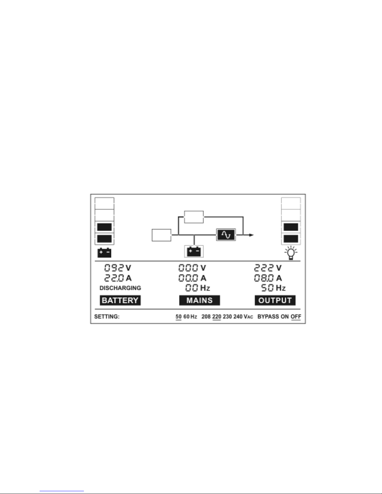
Il display LCD in modalità batteria è mostrato nel diagramma
sottostante. Sono visualizzati i dati relativi all’alimentazione, alla
batteria, al carico e all’uscita dell’UPS.
(1) Quando l’UPS è in modalità batteria, l’avvisatore acustico suona
ogni 4 secondi. Se si tiene premuto il pulsante “ON” sul pannello
frontale per più di 1 secondo, l’avvisatore smetterà di suonare
(modalità silenziosa). Tenere premuto il pulsante “ON” per più di 1
secondo per riattivare l’allarme.
(2) Lo stesso display viene visualizzato nella modalità test batteria.
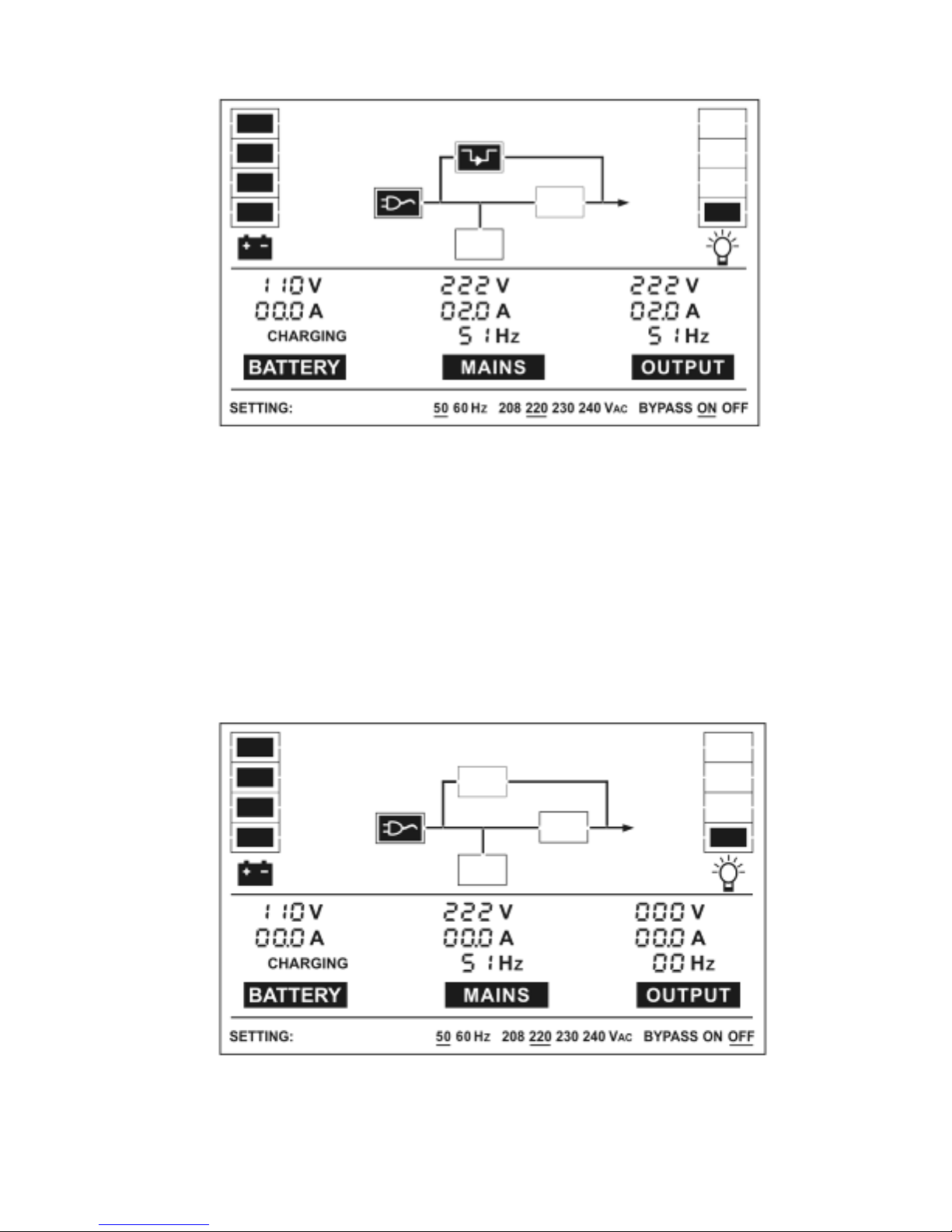
6.3 Modalità By-pass
Il display LCD in modalità By-pass è mostrato nel diagramma
sottostante. Sono visualizzati i dati relativi all’alimentazione, alla
batteria, al carico e all’uscita dell’UPS. In questa modalità l’UPS
emette un segnale acustico ogni 2 minuti.
Modalità batteria
Page 54
51
L’UPS non dispone della funzione di backup quando è in modalità
By-pass. L’energia assorbita dal carico viene fornita
dall’alimentazione di rete passando per il filtro interno.
.
6.4 Modaltà No output
Il display LCD in modalità No output è mostrato nel diagramma
sottostante. Sono visualizzati i dati relativi all’alimentazione, alla
batteria, al carico e all’uscita dell’UPS.
Modalità By-pass
Modalità No output
Page 55

52
6.5 Modalità anomala
In modalità anomala, dovuta a errori nel Bus ecc., verrà mostrato il
codice di errore corrispondente per indicare la modalità operativa
dell’UPS. Potrebbero comparire anche avvertimenti come “short!”, nel
caso in cui il carico o l’uscita dell’UPS sia basso e l’UPS sia in
modalità inverter guasto.
Page 56

53
7. Impostazioni tramite modulo LCD
Il voltaggio, la frequenza in uscita e la modalità By-pass si possono
selezionare direttamente tramite il modulo LCD. I valori selezionabili per il
voltaggio in uscita sono 208V, 220V, 230V e 240V. I valori selezionabili per
la frequenza in uscita sono 50Hz e 60Hz. La modalità by-pass può essere
abilitata o disabilitata. Tutte queste impostazioni possono essere
effettuate solo quando l’UPS è in modalità By-pass o in modalità No
output.
In modalità By-pass o No output, se si tiene premuto il pulsante “Select”
sul pannello LCD per più di un secondo, verrà visualizzata sul display una
linea nera lampeggiante sotto l’opzione “208V”. Premendo più volte il
pulsante "Select", la linea nera si sposterà di volta in volta sotto “220V”,
poi “230V”, “240V”, “50Hz”, “60Hz”, “Bypass Disable” (Disabilita modalità
By-pass), “Bypass Enable” (Attiva modalità By-pass). A questo punto, se
si tiene premuto il pulsante “Enter” per più di un secondo, la linea nera
smette di lampeggiare e il valore di voltaggio, della frequenza in uscita o
l'impostazione relativa alla modalità By-pass verrà modificata in base alla
selezione operata. Se per più di dieci secondi non viene premuto il
pulsante “Select” né il pulsante “Enter”, la linea nera lampeggiante
scomparirà.
Può essere selezionato sempre e solo un valore di voltaggio tra “208V”,
“220V”, “230V” e “240V” per volta, così come è possibile scegliere sempre
e solo uno dei due valori di frequenza (“50Hz” e “60Hz”). Il voltaggio e la
frequenza in uscita verranno modificati in base al valore corrispondente
scelto una volta selezionati i valori corretti sul pannello LCD e dopo che
l’UPS sia stato acceso mediante la pressione del pulsante “ON”. L’UPS
passerà alla modalità By-pass alcuni secondi dopo aver selezionato
“Bypass Enable” e tornerà alla modalità No output alcuni secondi dopo
aver selezionato “Bypass Disable”.
Page 57
54
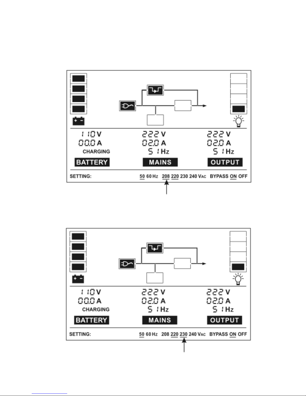
■■■■Esempio: istruzioni per cambiare il voltaggioin uscita da 220Vac a
230Vac tramite il pannello LCD.
Passo
1:
Premere il pulsante “Select”: sotto la scritta 208V apparirà
una linea nera lampeggiante.
Passo
2:
Premere il pulsante “Select” altre due volte: la linea
lampeggiante si sposterà sotto “230Vac”.
Page 58
55
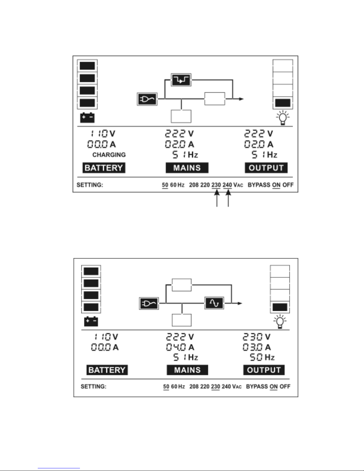
Passo
3:
Premere il pulsante “Enter” la linea sotto “230Vac” smette di
lampeggiare e si mette a lampeggiare sotto l’opzione successiva
(“240Vac”).
Passo
4:
La tensione in uscita risulterà impostato su 230Vac una
volta riavviato l’UPS.
Page 59

56
8. Risoluzione dei problemi
Se l’UPS presenta anomalie durante il funzionamento, verranno
visualizzati codici di allarme o di errore per indicare lo stato del sistema.
Possono comparire anche più allarmi contemporaneamente (in questo i
relativi codici verranno visualizzati ciclicamente). Quando si verifica un
errore, tutti gli allarmi precedenti non verranno più mostrati e saranno
sostituiti dal solo codice di errore.
Allarme ed errore Codice Allarme ed errore Codice
Errore nel Bus 05
Allarme: Fase-Neutro
invertite
09
Errore nell’inverter 06 Allarme: ventola 10
Errore (sovraccarico) 07
Allarme: sovratensione
batteria
11
Errore (temperatura
eccessiva)
08 Allarme: batteria bassa 12
Allarme: caricabatterie 13
Se il sistema UPS non funziona correttamente, provare a risolvere il
problema con l’aiuto della tabella seguente.
Problem Possible cause Remedy
Non c'è nessuna
indicazione né segnale
acustico di
avvertimento anche se
il sistema è connesso
alla rete di
alimentazione
Assenza di
voltaggio in
entrata
Controllare la presa di rete
domestica e il cavo di
alimentazione
Il display indica che
l’UPS è in modalità No
output o By-pass
benché l’alimentazione
di rete sia disponibile
L’inverter non è
stato attivato
Premere il pulsante “ON” e
accendere l’UPS
Page 60

57
Il display indica che
l’UPS è in modalità
batteria e l’allarme
acustico emette 1 beep
ogni 4 secondi.
La rete di
alimentazione è
interrotta o la
tensione e/o la
frequenza in
entrata non
rispettano i valori
di tolleranza
Il passaggio alla modalità batteria
è automatico. Quando l’allarme
acustico suona ogni secondo, la
batteria è quasi scarica.
Controllare la fonte di
alimentazione elettrica e se
necessario informare il fornitore.
Viene visualizzato il
codice di allarme 09
I conduttori della
fase e del neutro
in entrata nel
sistema UPS sono
invertiti
Ruotare di 180° la presa di
alimentazione e connettere il
sistema UPS.
Viene visualizzato il
codice di allarme 13,
allarme acustico una
volta al secondo
Caricabatterie o
batterie
danneggiate
Contattare il fornitore!!
Viene visualizzato il
codice di allarme 10
La ventola è
bloccata o non
funziona
Controllare le ventole e avvisare il
fornitore!!
Viene visualizzato il
codice di errore 07,
l’allarme acustico
suona una volta al
secondo
Sovraccarico
Disconnettere i carichi allacciati
all’uscita dell’UPS e riavviare.
Il codice di errore
visualizzato è 05, 06 o
08, l’allarme acustico
suona senza
interruzione
Guasto nell’UPS Contattare il fornitore!!
Il periodo di
alimentazione
d’emergenza è più
breve rispetto al suo
valore nominale
Batterie non
completamente
cariche / batterie
difettose
Caricare le batterie per almeno
1 ~ 2 ore e poi verificarne la
capacità. Se il problema persiste,
consultate il vostro fornitore.
Page 61

58
Tenere a portata di mano i seguenti dati prima di chiamare il servizio
post-vendita:
1. Numero del modello e numero di serie
2. Data in cui si è verificato il problema
3. Descrizione dettagliata del problema
9. Manutenzione
9.1 Funzionamento
Il sistema UPS non contiene parti riparabili dall’utente. Se la durata di
servizio della batteria (3~5 anni a 25°C di temperatura ambientale) è
stata superata, le batterie vanno sostituite. In questo caso, contattare
il vostro fornitore.
9.2 Stoccaggio
Se le batterie sono immagazzinate in zone dal clima temperato,
vanno caricate ogni 3 mesi per 1~2 ore. Ridurre gli intervalli di ricarica
a 2 mesi in luoghi soggetti ad alte temperature.
Page 62

59
10. Dati tecnici
10.1 Caratteristiche elettriche
INPUT (ENTRATA)
N° modello 1K(S) 2K 2KS 3K(S) 6K
6KS
Fase
Monofase
Frequenza (46~54)/(56~64) Hz
Corrente (A) 7A 9A 12A 16A 32A
50A
OUTPUT (USCITA)
N° modello 1K(S) 2K(S) 3K(S) 6K(S)
Potenza
1kVA/0.7kW 2kVA/1.4kW 3kVA/2.1kW
6KVA/4.2KW
Tensione
208/220/230/240×(1 士 2%)VAC
Frequenza
50/60×(1±0.2)Hz (Modalità batteria)
Forma d’onda sinusoidale
Il derating è pari al 10% quando la tensione in uscita è regolata sui
208VAC.
BATTERIE
N° modello 1K 2K 3K 6K
Numero e tipo
3×12V 7.2Ah 8×12V 7.2Ah 8×12V 7.2Ah 20×12V 7.2Ah
Page 63

60
10.2 Ambiente operativo
Temperatura Ambientale 0 oC to 40 oC
Umidità Operativa < 95%
Altitudine < 1000m
Temperatura di stoccaggio 0 oC ~ 40 oC
10.3 Dimensioni e pesi
N° Modello.
Dimensioni L x P x H
(mm)
Peso netto
(kg)
1K
482.6×470×88
16,3
1KS
482.6×470×88
9,1
Battery Pack 36V
482.6×470×88
17,5
2K
482.6×470×88
11,2
2KS
482.6×470×88
12,3
3K
482.6×470×88
11,2
3KS
482.6×470×88
12,3
Battery Pack 96V
482.6×470×88
22,5
6K
608×438×130
20
6KS
608×438×130
23,4
Battery Pack 240V
608×438×130
64,2
Page 64
61
11. Porte di comunicazione
11.1 Interfaccia RS232
Nella tabella seguente sono indicati i numeri e la descrizione dei pin
del connettore DB-9.
Pin # Descrizione I/O
2 TXD Output
3 RXD Input
5 GND Input
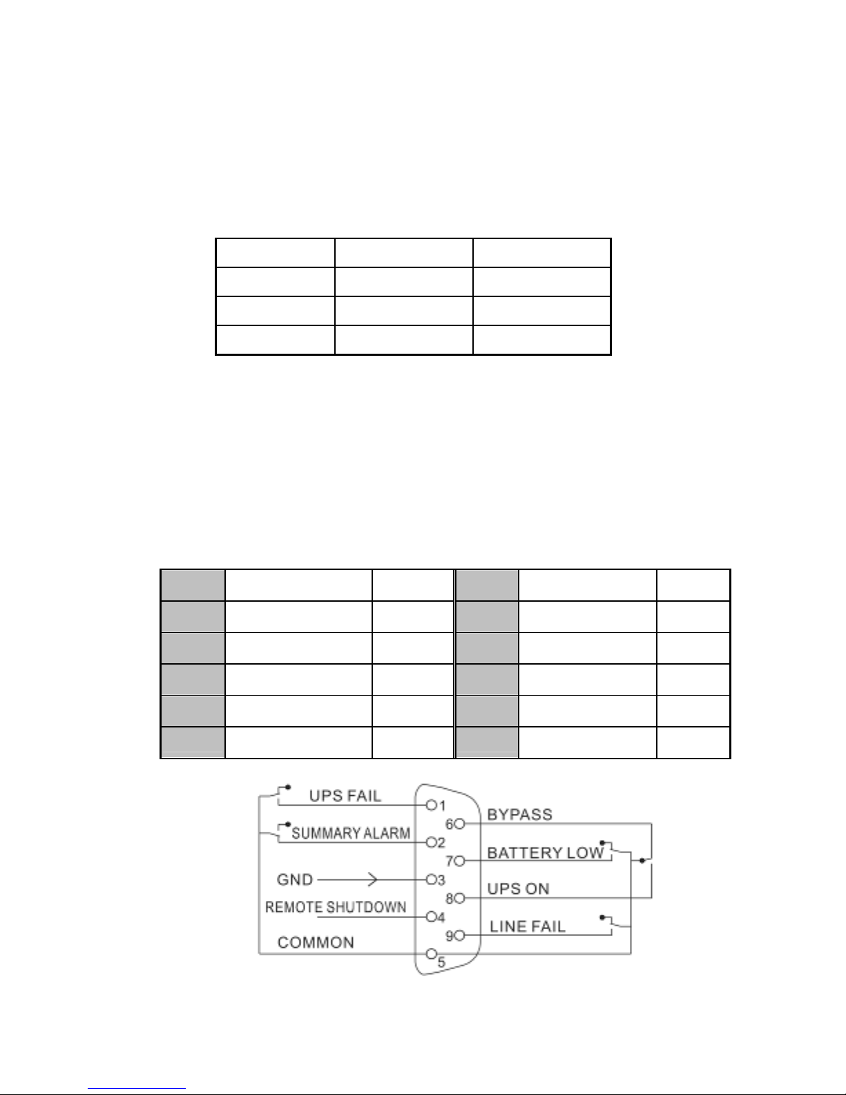
11.2 Interfaccia AS400 (Opzionale)
Oltre al protocollo di comunicazione summenzionato, questa serie
UPS dispone anche di una scheda AS400 come accessorio
opzionale per il protocollo di comunicazione AS400. Rivolgersi al
distributore locale per i dettagli. Nella tabella seguente sono indicati i
numeri e la descrizione dei pin del connettore DB-9 per la scheda
AS400.
Pin # Descrizione I/O Pin # Descrizione I/O
1 Errore UPS Uscita 6 By-pass Uscita
2 Somma allarmi Uscita 7 Batteria bassa Uscita
3 GND Ingresso
8 UPS attivo Uscita
4 Arresto a distanza Ingresso
9 Assenza rete Uscita
5 Comune Ingresso
DB-9 Interfaccia del protocollo di co
municazione
AS400
Page 65
62
12. Software per tutti i modelli
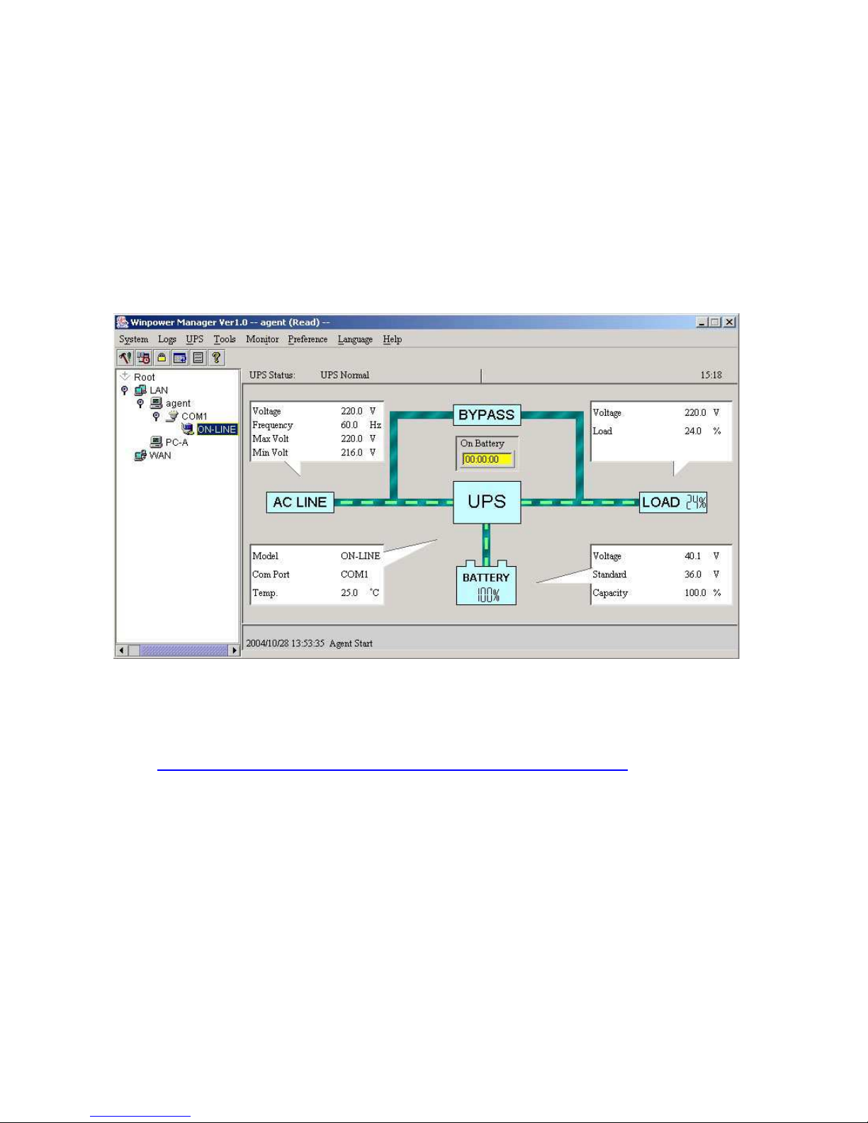
Download gratuito del Software WinPower
WinPower è un nuovo software di monitoraggio UPS che fornisce
un’interfaccia facile da usare per monitorare e controllare il proprio UPS.
Questo straordinario software permette lo spegnimento automatico e
sicuro per sistemi multicomputer durante un’interruzione di corrente. Con
questo software gli utenti possono monitorare e controllare tutti gli UPS su
una stessa LAN a prescindere dalla distanza a cui si trovano gli UPS.
Procedura: di Installazione
1. Andare sul sito web:
http://www.ups-software-download.com/winpower.htm
2. Scegliere il sistema operativo desiderato e seguire le istruzioni riportate
sul sito per scaricare il software.
3. Scaricando da internet tutti I file richiesti, digitare il numero di serie
511C1-01220-0100-478DF2A per installare il software.
Una volta riavviato il computer, il software WinPower comparirà
contrassegnato da un’icona rappresentante una spina verde nella system
tray, vicino all’orologio.
Page 66
63
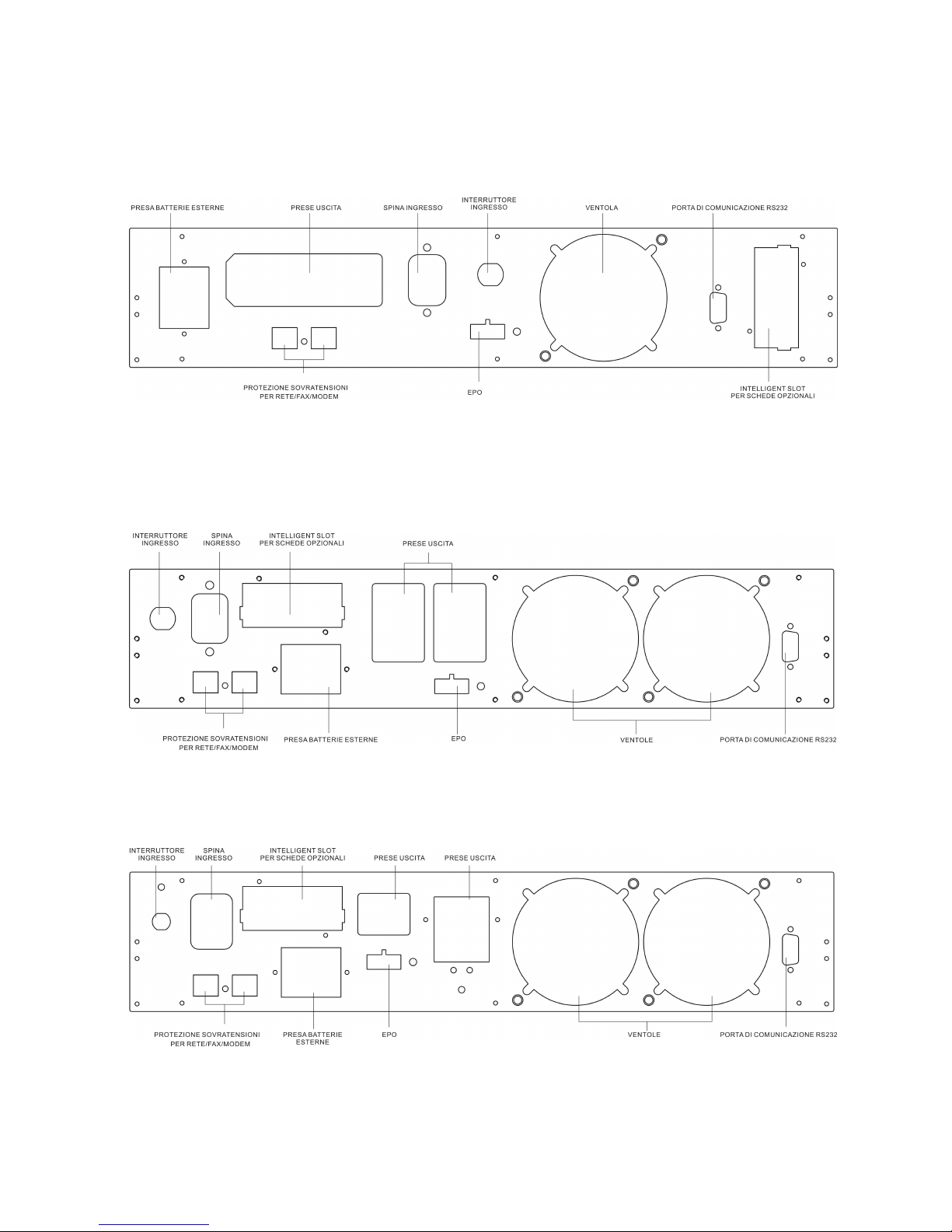
Appendice
Vista posteriore dei modelli 1K(S)
Vista posteriore del modello 2K
Vista posteriore dei modelli 2KS/3K(S)
Page 67
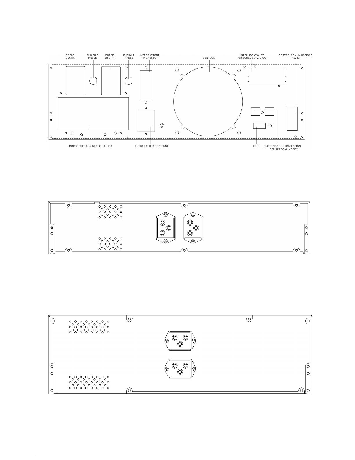
64
Vista posteriore dei modelli 6K(S)
Battery pack per i modelli
1-3KS
Battery pack per i modelli 6KS
 Loading...