

Page 1
HOTSPOT-1000
410-2410-001 EN11
EN
Installation - Operation - Maintenance
Thermographic Surface Temperature Detector
HOTSPOT-1000
GTE Industrieelektronik GmbH
Helmholtzstr. 21, 38-40 | D-41747 Viersen, GERMANY | info@gte.de | +49(0)2162 / 3703-0 | www.gte.de
Page 2

ADICOS HOTSPOT-1000 Operating manual
Document version:410-2410-001 EN11
– Translation from German –
Manufacturer:
GTE Industrieelektronik GmbH
Helmholtzstr. 21, 38-40
41747 Viersen
GERMANY
Support hotline: +49 (0)2162 /37030
E-mail: service@adicos.de
© 2018 GTE Industrieelektronik GmbH – This document and all illustrations contained herein are protected by copyright and may not be copied and pasted, modified or distributed without the express consent of
the manufacturer!
Technical data is subject to change without notice!
Page 3

Brief Description
The Advanced Discovery System (ADICOS) is used for early detection of hot spots in industrial
environments. It is comprised of various separate detector units that are positioned and parameterized to facilitate a detection goal specified during the planning phase in a way that is not
susceptible to breakdown and malfunctioning.
The detector units are linked to a central unit through an ADICOS M-Bus.
In the central unit the parameterization of each detector is specified. All of the sensor data
needed for statistical analyses are also stored in the central unit.
The ADICOS HOTSPOT-1000 is an IR fire detector used for optical and spatially resolved fire
and heat detection. It is well suited for these applications:
■ Detection of hot surfaces
■ Detection of flaming fires
■ Detection of moving hot spots (pockets of embers)
■ Monitoring of machinery and parts
ADICOS HOTSPOT-1000
410-2410-001 EN11
I
Page 4

Table of Contents
1 About this Manual .......................................... 1
1.1 Objective ........................................... 1
1.2 Explanation of Symbols .................................. 1
1.3 Abbreviations......................................... 2
1.4 Storing this Manual ..................................... 2
2 For your Safety ............................................ 3
2.1 Intended Use ......................................... 3
2.2 Unintended Use ....................................... 3
2.3 Standards and Regulations ................................ 3
2.4 Qualification Required of Personnel .......................... 4
2.5 Modifications......................................... 4
2.6 Accessories and Spare Parts ............................... 4
3 Product Description.......................................... 5
3.1 Overview ........................................... 5
3.2 Sensor Specification .................................... 5
3.3 Potential Uses......................................... 6
3.4 Connecting Purge Air . . . . . . . . . . . . . . . . . . . . . . . . . . . . . . . . . . . 6
3.5 Signal Relays ......................................... 8
3.6 Detector Heater ....................................... 8
3.7 ADICOS M-Bus ....................................... 8
4 Functioning ............................................... 8
4.1 Configuration and Evaluation .............................. 9
4.2 LED Signals .......................................... 9
5 Installation ............................................... 10
5.1 Requirements of Mounting Location........................... 10
5.2 Mounting ........................................... 13
5.3 Wiring ............................................. 14
6 Commissioning ............................................ 22
II
410-2410-001 EN11
ADICOS HOTSPOT-1000
Page 5

7 Operation ............................................... 23
7.1 Software Access ....................................... 23
7.2 Alarm .............................................. 23
8 Maintenance.............................................. 25
8.1 Dirt and Condensation................................... 25
8.2 Checking Signal Relay Functioning........................... 26
8.3 Function Text ......................................... 26
8.4 Replacing Detectors..................................... 26
9 Failure .................................................. 27
10 Technical Data ............................................ 28
10.1 Measuring Range ...................................... 29
10.2 Precision of Standard Version ADICOS HOTSPOT-1000 ............ 29
10.3 Purge Air Requirements................................... 30
11 Disposal................................................. 30
ADICOS HOTSPOT-1000
410-2410-001 EN11
III
Page 6

ABOUT THIS MANUAL
1 About this Manual
1.1 Objective
This manual describes how to properly attach, wire, start up and operate the ADICOS detectors “HOTSPOT-1000.” Once the device has been successfully started up, this document
serves as a reference in the event of malfunctions.
It is intended to be used only by properly qualified personnel (–› Chap. 2, For your Safety).
1.2 Explanation of Symbols
This manual follows a certain structure to make it easy to work with and understand. The
following designations are used throughout.
Operational objectives
Operational objectives specify the result to be achieved by following the subsequent instructions. Operational objectives are shown in bold print.
Instructions
Instructions are the steps to be taken in order to achieve the previously stated operational
objective.
Instructions appear like this
► Indicates a single instruction
1 First of a series of instructions
2 Second of a series of instructions
3 etc.
Intermediate states
When it is possible to describe intermediate states or events resulting from the instruction steps
(e.g. screens, internal function steps, etc.), they are shown like this:
Z Intermediate state
Warnings
The following types of notes are used through this manual:
NOTE!
Indicates information relevant to further operation of the equipment.
1
410-2410-001 EN11
ADICOS HOTSPOT-1000
Page 7
WARNING!
Signals a hazard that can cause death or serious injury.
DANGER!
Indicates a hazard that will immediately cause death or serious injury.
1.3 Abbreviations
The following abbreviations are used through this manual:
Abbr. Meaning
ADICOS
AAB
BMZ
M-BM
NT
FDnet
LSN
BMA
Advanced Discovery System
ADICOS branching and connection box
ADICOS control panel BMZ-30
ADICOS M-BUSMASTER
ADICOS power supply unit NT V40-A3
Field Device Network (fire detection bus, SIEMENS fire detection systems)
Local Security Network (fire detection bus, BOSCH fire detection systems)
Fire detection system
ABOUT THIS MANUAL
1.4 Storing this Manual
Store this manual near the detectors, in a place where it can easily be accessed when needed
for reference.
ADICOS HOTSPOT-1000
410-2410-001 EN11
2
Page 8

FOR YOUR SAFETY
2 For your Safety
When properly installed, started up, operated and serviced, ADICOS HOTSPOTs ensure operational safety at your facility. But it is imperative that the manual, including all safety notes, be
read, understood and followed completely.
WARNING!
Incorrect installation and operating errors can cause death, serious
injury and damage to industrial equipment.
− Read the entire manual and follow the instructions!
2.1 Intended Use
The thermal imaging camera ADICOS HOTSPOT-1000 is designed in line with state-of-the-art
technology and accepted safety regulations.
The ADICOS HOTSPOT-1000 may be used only in compliance with the limits stated as technical operating specifications. These can be found in Chap. 10, »Technical Data«.
Intended use also includes following the instructions in this manual and complying with all
relevant local regulations.
The ADICOS HOTSPOT-1000 may not be used for any other purpose. If the device is used in
any other way, or if changes are made to the product, including in the course of installation
and maintenance, the warranty claim is no longer valid.
2.2 Unintended Use
The ADICOS HOTSPOT-1000 may not be installed in potentially explosive areas.
There are special HOTSPOT models available for use in potentially explosive areas.
2.3 Standards and Regulations
The safety and accident prevention regulations relevant to the specific application must be
complied with when installing, starting up, servicing and inspecting the detector.
The following standards and directives are particularly important when working in potentially
explosive atmospheres:
3
410-2410-001 EN11
ADICOS HOTSPOT-1000
Page 9
FOR YOUR SAFETY
Regulation Description
VDE 0100 Erection of power installations with rated voltages below 1000 V
VDE 0800 Telecommunications – general concepts; requirements and tests for the
safety of facilities and apparatus
VDE 0833 Alarm systems for fire
VdS 3189 IR camera units for monitoring temperatures in fire prevention
VDE 0845 Protection of telecommunication systems against lightning, electrostatic
discharges and overvoltages from electric power installations –
provisions against overvoltages
VdS 2095 Guidelines for automatic fire detection and fire alarm systems - planning
and installation
DIN 14675 Fire detection and fire alarm systems – setup and operation
2.4 Qualication Required of Personnel
Only properly trained and qualified persons may work on ADICOS equipment. Qualified persons are those who have received relevant professional training, have the required skills and
experience and who are aware of applicable regulations, enabling them to work on electrical
equipment and detect potential hazards.
WARNING!
Installation, startup, parameterization and maintenance may be performed only
by authorized and properly trained personnel.
2.5 Modications
WARNING!
All kinds of unauthorized modifications or additions to the equipment
are expressly prohibited!
− When in doubt, consult the manufacturer!
2.6 Accessories and Spare Parts
WARNING!
Only original spare parts and accessories provided by the manufacturer may
be used!
WARNING!
Original spare parts and accessories may be installed only by properly trained
personnel.
ADICOS HOTSPOT-1000
410-2410-001 EN11
4
Page 10
PRODUCT DESCRIPTION
3 Product Description
The ADICOS HOTSPOT-1000 is an infrared fire detector with an integrated signal evaluator
for which the parameters can be individually configured.
Because of its durable design, the ADICOS HOTSPOT-1000 can be used in adverse industrial
environments. It is ideal for monitoring bulk goods prone to spontaneous combustion as well
as conveyor lines.
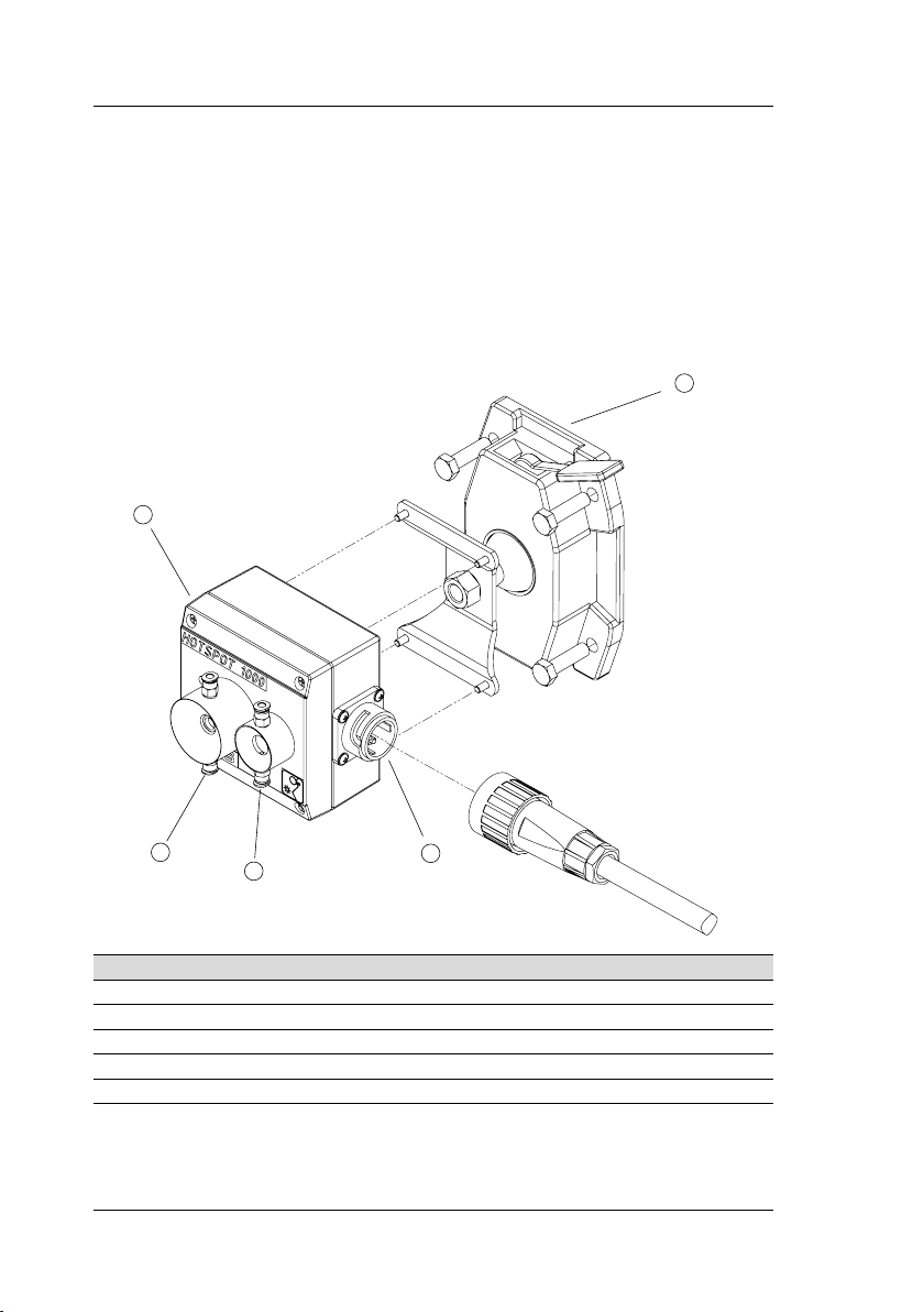
3.1 Overview
4
3
No. Description
Pre-assembled bayonet connection
Camera as installation aid
Purge air adapter with IR sensor array
HOTSPOT-1000 enclosure
Adjustable mounting bracket
5
1
2
3.2 Sensor Specication
5
410-2410-001 EN11
ADICOS HOTSPOT-1000
Page 11

PRODUCT DESCRIPTION
Type Pixels Capture angle
Object resolution
at a distance
of 5 meters
HOTSPOT-1000 32 x 31 53° x 52° 14 cm
3.3 Potential Uses
3.3.1 Moving Objects
Because of the quick reaction time of 100 milliseconds, the ADICOS HOTSPOT-1000 is ideal
for monitoring moving objects, e.g. transport and conveyor belts. This means that hot spots on
transport and conveyor belts can be found early.
When installing the ADICOS HOTSPOT-1000, ensure that the detector always has a clear,
unobstructed view of the transport or conveyor belt to be monitored. If it is not possible to scan
and monitor the entire moving object with a single ADICOS HOTSPOT-1000, you can install
multiple detectors, positioning them such that together they can scan and monitor the whole
object.
3.3.2 Stationary Objects
The ADICOS HOTSPOT-1000 can monitor immobile, stationary objects as well, ensuring
early detection of any hot spots that may be forming. The detector also senses overheated
drives, shaft bearings and reels early.
And the ADICOS HOTSPOT-1000 can be used in conjunction with the GSME to monitor bulk
goods stored above storage sites or in silos and to quickly detect any hot spots.
As with moving objects, you can use multiple ADICOS HOTSPOT-1000s at the same time, if it
is not possible to scan and monitor the entire area required with only a single device.
3.4 Connecting Purge Air
The ADICOS HOTSPOT-1000 optics can be found in an air settling tube that prevents dust
from collecting on the lens at low air flow or turbulence. But when the air flow is greater or
the air rate is faster, the air settling tube can no longer prevent the ADICOS HOTSPOT-1000
optics from getting dirty. The ADICOS HOTSPOT-1000 has a purge air connection to ensure
that the optics stay clean even when exposed to strong turbulence and high wind speeds.
It is essential to provide a continuous supply of purge air as long as dust residue can be anticipated.
ADICOS HOTSPOT-1000
410-2410-001 EN11
6
Page 12

PRODUCT DESCRIPTION
Purge air connection
The oil-free and dust-free compressed air available on site is used. The compressed air for
the sensor/camera is supplied to the purge air connection through a throttle valve (T-fitting).
The purge air has to be adapted to the temperature of the air around the HOTSPOT-1000 to
prevent condensation from forming on the lens of the IR sensor.
Purity classes required for purge air
Dust class 2
Water content class 3 (-20 °C dewpoint)
Oil content class 2 (< 0.1 mg/m3)
Required air ow rate
In dusty, settled air >2 l/min
In dusty, flowing air >10 l/min
Testing is advisable in severely turbulent, dusty air.
The purge air supply must remain uninterrupted as long as dust residue can be expected. The
air flow rate can be restricted with throttle valves; one per detector, e.g. from the Festo series
GR-QS4-LF, Festo art. no. 193966.
7
410-2410-001 EN11
ADICOS HOTSPOT-1000
Page 13

FUNCTIONING
3.5 Signal Relays
The ADICOS HOTSPOT-1000 has two signal relays: one for the state “Alarm” and
one for the state “Failure”. The “Alarm” relay is a make contact (NO) and the “Failure” relay is a break contact (NC). The signal lines for the relays are integrated into the
ADICOS connection cable.
3.6 Detector Heater
The ADICOS HOTSPOT-1000 is equipped with an internal heater. It heats the enclosure,
thus preventing humidity from the environment from forming condensation. When the heater is
operating, it can be activated and deactivated via the ADICOS service software. The detector
heater has a power consumption of up to 10 VA and is delivered in an inactive state.
The heater switches off automatically when undervoltage occurs. When the undervoltage has
been remedied, the detector heater is not activated again until the ADICOS HOTSPOT-1000
has been reset.
The enclosure temperature is monitored to limit the heating function. If the default upper temperature limit of 40 °C is exceeded, the detector heater switches off automatically until the
enclosure temperature has fallen again. The limit may need to be adjusted in the event of
a high ambient temperature along with high humidity. Details can be found in the software
documentation.
3.7 ADICOS M-Bus
The ADICOS M-Bus is a two-wire data line used to transmit all of the detector parameters as
well as the operating and measurement data to the central unit (ADICOS BMZ-30/M-Busmaster) used. These data can be displayed and archived using the ADICOS service software. The
parameters for all of the connected detectors can be set via the ADICOS M-Bus as well. The
M-Bus lines are integrated into the ADICOS connection cable.
4 Functioning
When the ADICOS HOTSPOT-1000 is in operation, it triggers an alarm according to the set
limit combinations. When an ADICOS central unit (ADICOS BMZ-30, ADICOS M-Busmaster)
is used, the detector also transmits all sensor and operating data via M-Bus to the ADICOS
service software to be displayed.
If the ADICOS HOTSPOT-1000 is connected to a fire panel (ADICOS BMZ-30 or a fire panel
from a different supplier), the fire panel controls the detector’s alarm display.
ADICOS HOTSPOT-1000
410-2410-001 EN11
8
Page 14

FUNCTIONING
4.1 Conguration and Evaluation
One of the outstanding features of the ADICOS HOTSPOT-1000 is its capacity to flexibly and
quickly detect hot spots. The detector has a separate alarm threshold for each individual pixel.
In addition to overtemperature, it also detects flames. Each detector has two sets of limits.
Standard conguration
In the standard configuration, the temperature threshold of the ADICOS HOTSPOT-1000 is
set to 60 °C.
Individual modications to conguration
The ADICOS service software can be used to change the limit of the ADICOS
HOTSPOT-1000 irrespective of the standard (default) configuration upon delivery.
4.2 LED Signals
The current state of the ADICOS HOTSPOT-1000 is indicated by three LEDs.
The following table explains the respective illumination.
LED State Functioning
Green Flashing Initialization / not yet able to trigger an alarm
On Normal operation
Off Detection system off / detector, circuit breaker or
cable defective
Yellow On Malfunction mode
Off Normal mode
With re panel interface:
Red Flashing Detector alarm, but without alarm at the fire panel
On alarm at the fire panel
Off Normal mode
With pre-alarm module:
Red Flashing Pre-alarm
On Alarm
Off Normal operation
Without re panel interface:
Red On Alarm
Off Normal operation
9
410-2410-001 EN11
ADICOS HOTSPOT-1000
Page 15

INSTALLATION
5 Installation
WARNING!
Incorrect installation of ADICOS detectors can cause malfunctioning, leading to
failure of the fire detection system.
− Only properly trained personnel may perform installation work.
5.1 Requirements of Mounting Location
DANGER!
Standard model ADICOS HOTSPOTs may not be installed
in potentially explosive areas!
There are special HOTSPOT models available for use in potentially explosive
areas.
WARNING!
The correct position and direction of the ADICOS HOTSPOT-1000 are essential
to proper and reliable detection. If the device is not placed correctly,
the detector could be completely ineffective!
5.1.1 Protective Measures
To ensure smooth operation of the ADICOS HOTSPOT-1000, always consider the following
factors when choosing a place to attach the device.
Temperature
Even under the most unfavorable conditions, the ambient temperature at the mounting location
must remain within the temperature range specified for the ADICOS HOTSPOT-1000 (Refer to
Chap. „10 Technical Data“).
Dirt and condensation
The ADICOS HOTSPOT-1000 is equipped with a purge air connection that prevents dusty
air from polluting the optics. A detector heater is needed when there is a risk of condensation
forming on the device.
Moisture
When choosing a place to attach the ADICOS HOTSPOT-1000, take into consideration that it
may not be exposed to moisture. Keep in mind that water could be used for cleaning purposes
near the mounting location.
ADICOS HOTSPOT-1000
410-2410-001 EN11
10
Page 16

INSTALLATION
Vibration
The electronics contained in the ADICOS HOTSPOT-1000 can be damaged when subjected
to vibration. If there are any sources of strong vibration near where the ADICOS HOTSPOT-1000
is mounted, the detector has to be positioned such that it is immune to the vibration.
Electromagnetic radiation
The electronics contained in the ADICOS HOTSPOT-1000 can be impaired by electromagnetic radiation. So do not place the detector near high voltage equipment. And always use
shielded cable.
5.1.2 To Ensure Proper Detection
To ensure reliable and correct operation of the ADICOS HOTSPOT-1000 as well as proper
detection, always consider the following factors when choosing a place to attach the device.
Visibility
The ADICOS HOTSPOT-1000 must always have a clear, unobstructed view of the material to
be monitored. If the object to be monitored is obscured or is not within the visibility range of
the ADICOS HOTSPOT-1000, the device will not be able to detect any heat sources and
trigger an alarm.
Distance and detection area
The detection area is determined by the distance between the detector and the object to be
monitored. So the distance or the installation location should be selected such that the object to
be monitored can be covered completely by the detector’s field of view. This ensures maximum
sensitivity.
Detection area when positioned vertically: tan(26.5) x 2 x height
Example:
An 80 cm wide conveyor belt is to be monitored to detect any moving hot spots. So the
HOTSPOT detector should be installed about 80 - 100 mm above the transport belt.
Distance [m] Object resolution [cm] Width of detection area [m]
1 3 1
3 10 3
5 16 5
10 32 10
15 48 15
11
410-2410-001 EN11
ADICOS HOTSPOT-1000
Page 17

52
distance (h)
object to be monitored
detection area
INSTALLATION
As the distance increases, so do the size of the total detection area and the area detected by
a single sensor pixel. So the object resolution of the IR detectors is a factor of the distance.
Disruptions
Certain disruptive variables can have a negative impact on functioning of the ADICOS
HOT-SPOT-1000, leading to a false alarm. When setting the alarm thresholds, take into con-
sideration intended heat sources, e.g. motor vehicles.
ADICOS HOTSPOT-1000
410-2410-001 EN11
12
Page 18

INSTALLATION
5.2 Mounting
WARNING!
ADICOS HOTSPOT-1000 detectors have to be installed with the enclosure
closed.
− Do not open the enclosure!
1
Select a suitable mounting location.
2 Install the GTE connection box near the ADICOS HOTSPOT-1000.
3 If applicable, use a 4 mm hose to connect the ADICOS HOTSPOT-1000 to a purge
air supply. This prevents residue from forming on the ADICOS HOTSPOT-1000 optics.
4 Connect the components to one another (Refer to chapter 5.3).
5 Connect the components to the supply voltage.
5.2.1 Installation Requirements
The most important requirement for properly detecting a heat source is that the detector must
have a clear, unobstructed view of the equipment parts and/or objects to be monitored within
the detection area.
Before mounting the device, determine the detection area of a single detector, or adjust it as a
factor of the installation location. When doing this, take into consideration the mounting angle
of the detector as well as the angle of detection.
5.2.2 Mounting the ADICOS HOTSPOT-1000
NOTE!
The ADICOS HOTSPOT-1000 may be installed only by properly trained personnel.
Attaching to a mounting plate
The aluminum enclosure of the ADICOS HOTSPOT-1000 has four mounting bores with a
thread cut of M5 in the lower part. These mounting bores/threads can be used to mount the
detector directly or to attach it to a mounting plate. A standard mounting plate is available as
an accessory.
The person installing the device must verify that the mounting plate is positioned such that
the equipment parts to be monitored are within the detection area of the ADICOS HOT-
SPOT-1000.
13
410-2410-001 EN11
ADICOS HOTSPOT-1000
Page 19

INSTALLATION
Attaching to a mounting bracket
The ADICOS HOTSPOT-1000 is also available with a ball joint. The ball joint is connected
to the detector with a screw fitting in the center of the back of the enclosure. There is a lever
that can be released to adjust the detector to the proper angle, allowing it the best view of the
detection area. The ball joint gives the ADICOS HOTSPOT-1000 a tilting range of +/- 50°
from the vertical position towards the narrower side and +/- 30° from the vertical position
towards the wider side.
5.3 Wiring
WARNING!
Incorrect installation of the ADICOS HOTSPOT-1000 can cause malfunctioning
and failure of the detection system.
− Only properly trained personnel may wire the equipment! (–› Chap.
2.4, Qualication Required of Personnel)
− Deenergize the entire detection system before wiring any part of it!
− Use only ADICOS connection cables and ADICOS branching and con-
nection boxes to connect the detector!
ADICOS HOTSPOT-1000
410-2410-001 EN11
14
Page 20

INSTALLATION
5.3.1 Cable Assignment
Color Signal Potential-free contact
Red
Black
Operating voltage
24 ... 40 V DC, non-polarized
Yellow Relay output X6 e Alarm (NO)
White Relay output X6 a Alarm (NO)
Brown Relay output X7 a Failure (NC)
Green Relay output X7 e Failure (NC)
Pink Fire panel interface B – in Auxiliary assembly (option-
Blue Fire panel interface A – in
al, added at factory)
Violet Fire panel interface B – out
Gray Fire panel interface A – out
Blue/red
Gray/
pink
M-Bus
Max, 40 V, non-polarized
1
With series resistor, standard 680 Ω
1
1
15
410-2410-001 EN11
ADICOS HOTSPOT-1000
Page 21

Optional re panel interfaces
Color Signal Siemens FDnet BOSCH LSNi
Pink Fire panel interface B – in FDnet-A (–) LSN b1 in
Blue Fire panel interface A – in FDnet (+) LSN a in
Violet Fire panel interface B – out FDnet-B (–) LSN b2 out
Gray Fire panel interface A – out FDnet (+) LSN a out
Optional analog signal
Color Signal Analog signal
Pink Analog signal – protected
4 ... 20 mA
against polarity reversal
Blue Analog signal – protected
4 ... 20 mA
against polarity reversal
Violet Analog signal 0 ... 5 V
0 ... 10 V
Gray Analog signal 0 V
Optional pre-alarm relay
INSTALLATION
Color Plug assignment Pre-alarm module
Pink 8 NC (break contact)
Blue 9 Violet 10 M (center tap)
Gray 11 NO (make contact)
The pre-alarm relay is linked to set 2 of the trigger limits. The pre-alarm functionality is ensured
as long as the limits programmed in set 2 are less sensitive than the limits in set 1.
ADICOS HOTSPOT-1000
410-2410-001 EN11
16
Page 22

INSTALLATION
5.3.2 Attaching ADICOS Connection Cable to ADICOS HOTSPOT-1000
1 Press the bayonet lock on the ADICOS connection cable against the
detector connection.
2 Carefully turn the entire bayonet lock to find the proper position for the
twist protection.
3 Firmly turn the bayonet ring on the connector to secure the cable.
17
410-2410-001 EN11
ADICOS HOTSPOT-1000
Page 23

INSTALLATION
5.3.3 Attaching ADICOS Connection Cable to ADICOS-AAB
The exact way in which the ADICOS connection cable and the ADICOS branching and connection box (ADICOS-AAB) are wired is a factor of the system and detector configuration. The
following procedure applies to all wiring variations.
CONNECTION BOX
BMZ30 / M-BM
NT V40-A3
+24 V
X7 (St)
X6aus (Al)
X6ein (Al)
LOOP B
LOOP A
M-Bus A
M-Bus B
+24 V
0 V
0 V
PE
PE
+24 V
0 V
M-Bus A
M-Bus BB1A1B2A2
+24 V
0 V
X7 (St)
X6aus (Al)
X6ein (Al)
LOOP B
LOOP A
M-Bus A
M-Bus B
X6e
X7e
X6a
X7a
ADICOS HOTSPOT-1000
BMZ-Module
R
R
1
2
Alarm relay
Standard
R1 = 680 Ω R2 = ∞
HOTSPOT
410-2410-001 EN11
R
3
Failure relay
R3 = 0 Ω R4 = ∞
R
4
Standard
18
Page 24

INSTALLATION
Wiring ADICOS-AAB
1
Open the cover on the ADICOS-ABB enclosure
2 Open the lower cable gland on the ADICOS-ABB
3 Thread the ADICOS connection cable through the lower cable gland and into the ADI-
COS-ABB
4 Connect the cable cores to the ADICOS-ABB connecting terminals as shown in the wiring
diagram
5 Close the cable gland on the ADICOS-ABB
6 Close the cover on the ADICOS-ABB enclosure
NOTE!
More information on how to install the ADICOS branching and connection box
can be found in the GTE manual, no. 430-2410-001!
5.3.4 Wiring Variations
The actual wiring of the detector to the ADICOS branching and connection box can vary
depending on the system configuration. The following wiring diagrams show the most common
system configurations and wiring variations.
ADICOS BMZ / M-BM and external NT
ADICOS BMZ-30
M-Busmaster
ADICOS Power supply unit
NT V40-A3
19
+ (24 V)
− (24 V)
M-Bus
M-Bus
0 V
+40
+24 V
ADICOS-AAB
0 V
X7 (Stoer)
X6aus (Al)
X6ein (Al)
LOOP B
LOOP A
M-Bus A
M-Bus B
0 V
+24 V
PE
PE
V
+24 V
red
0 V
black
M-Bus A
yellow
M-Bus B
green
B1
white
A1
brown
B2
A2
pink
blue
X6e
violet
X7e
gray
X6a
X7a
blue/red
gray/pink
+
24 V
0 V
X7 (Stoer)
X6aus (Al)
X6ein (Al)
LOOP B
LOOP A
M-Bus A
M-Bus B
to next
ADICOS-AAB
ADICOS-connection cable for detector
410-2410-001 EN11
ADICOS HOTSPOT-1000
Page 25

Limit value detection lines “Failure” and “Alarm”
INSTALLATION
External fire detector
Failure
Alarm 1
Alarm 2
+24 V
0 V
X7 (Stoer)
X6aus (Al)
X6ein (Al)
LOOP B
LOOP A
M-Bus A
M-Bus B
0 V
+24 V
PE
PE
ADICOS-AAB
B1
0 V
+24 V
M-Bus B
M-Bus A
red
white
black
green
yellow
A1
brown
+24 V
0 V
X7 (Stoer)
X6aus (Al)
X6ein (Al)
LOOP B
LOOP A
M-Bus A
M-Bus B
At the end of the line:
B2
A2
X6e
X7e
X6a
X7a
pink
blue
gray
violet
blue/red
gray/pink
Terminating resistor
wire break detection
ADICOS connection cable for detector
External re detector LOOP with LSN / FDnet (internal re panel interface)
External fire detector
(with Siemens FDnet
or Bosch LSN)
LOOP B
LOOP A
+24 V
0 V
X7 (Stoer)
X6aus (Al)
X6ein (Al)
LOOP B
LOOP A
M-Bus A
M-Bus B
0 V
+24 V
PE
PE
ADICOS-AAB
B1
0 V
+24 V
M-Bus B
M-Bus A
+24 V
0 V
X7 (Stoer)
X6aus (Al)
X6ein (Al)
LOOP B
LOOP A
M-Bus A
M-Bus B
A1
B2
A2
X6e
X7e
X6a
X7a
3k3
to next
ADICOS-AAB
to next
ADICOS-AAB
ADICOS connection cable for detector
ADICOS HOTSPOT-1000
red
black
yellow
green
white
brown
pink
blue
410-2410-001 EN11
violet
gray
blue/red
gray/pink
*
Detector with integrated
*
FDnet or LSNi module
20
Page 26

INSTALLATION
External re detector LOOP with other bus (external re panel interface)
External fire detector
(fire alarm bus)
LOOP B
LOOP A
External fire panel interface
LOOP B
LOOP A
+24 V
0 V
X7 (Stoer)
X6aus (Al)
X6ein (Al)
LOOP B
LOOP A
M-Bus A
M-Bus B
0 V
+24 V
PE
PE
+24 V
red
0 V
black
Alarm 1
Alarm 2
Störung 1
Störung 2
ADICOS-AAB
B1
A1
B2
A2
M-Bus B
M-Bus A
pink
blue
white
green
brown
yellow
X6e
violet
X7e
gray
X6a
X7a
blue/red
gray/pink
LOOP B
LOOP A
+24 V
0 V
X7 (Stoer)
X6aus (Al)
X6ein (Al)
LOOP B
LOOP A
M-Bus A
M-Bus B
to next
fire panel
interface
ADICOS connection cable for detector
Primary cable shield
ADICOS-AAB
+24 V
Primary cable Primary cable
0 V
X7 (Stoer)
X6aus (Al)
X6ein (Al)
LOOP B
LOOP A
M-Bus A
M-Bus B
0 V
+24 V
PE
PE
+24 V
0 V
X7 (Stoer)
X6aus (Al)
X6ein (Al)
LOOP B
LOOP A
M-Bus A
M-Bus B
21
B1
A1
0 V
+24 V
M-Bus B
M-Bus A
410-2410-001 EN11
B2
A2
X6e
X7e
X6a
X7a
ADICOS HOTSPOT-1000
Page 27

6 Commissioning
DANGER!
ADICOS systems work with electrical current, which can cause equipment damage and fire if not installed properly.
− Before switching on the system, verify that all detectors are properly
mounted and wired.
− Startup may be performed only by properly trained personnel.
WARNING!
Before startup, check that all of the detector enclosure covers are completely
closed; otherwise the ADICOS will not work. If the enclosure cover is not closed
properly, a false alarm can be triggered or the detector can fail.
NOTE!
The ADICOS detectors do not have to each be started up separately. When the
ADICOS central unit is switched on, all of the detectors start automatically.
NOTE!
The ADICOS HOTSPOT-1000 indicates a malfunction until
the startup process is completed.
COMMISSIONING
► Supply voltage to the device to start up the ADICOS HOTSPOT-1000.
► Start up the ADICOS system as described in the manual for the central unit used (ADICOS
BMZ-30/M-Busmaster).
Z Startup begins automatically and takes about ten seconds.
Z The green signal LED “Operation” flashes briefly.
Z The detector electronics are initialized.
Z Once startup is completed, the green signal LED “Operation” remains illuminated.
ADICOS HOTSPOT-1000
410-2410-001 EN11
22
Page 28

OPERATION
7 Operation
During operation, the ADICOS HOTSPOT-1000 monitors the area within its field of view and
triggers an alarm when the limits are exceeded. The scan interval is 100 milliseconds.
7.1 Software Access
When an ADICOS central unit (BMZ-30, M-Busmaster) is used, detailed information on the
detector can be called up via the M-Bus. To be able to access the detector information, you
will need a PC on which the ADICOS service software is installed and that is connected to the
ADICOS central unit.
The communication number (COM or K.N.) shown on the ID plate and on the front of the detector is used to access detailed information on the detector in the software. Parameterization
of the ADICOS HOTSPOT-1000 is also done in the software. However, only properly trained
personnel may perform this task. And in the software you can also look at the current thermal
image of the detector, enabling potential sources of ignition to be revealed.
7.2 Alarm
If the temperature limits set in the ADICOS HOTSPOT-1000 are exceeded, the ADICOS
HOTSPOT-1000 triggers an alarm. The internal alarm relay is engaged and the red LED lights
up. The alarm signal is transmitted to the connected fire panel via the ADICOS M-Bus or the
fire detection lines.
If an alarm delay has been set, the alarm is not triggered until the alarm conditions have been
met for longer than the set duration.
7.2.1 Fire Detection System Operation
If the ADICOS HOTSPOT-1000 is connected to a fire panel, the alarm is transmitted to the fire
panel via the fire detection system module. The fire detection system triggers the ADICOS
HOTSPOT-1000 alarm. And the alarm relay is triggered and the red signal LED ADICOS
HOTSPOT-1000 lights up. If despite all of this the fire detection system does not trigger the
ADICOS HOTSPOT-1000 alarm, the red LED flashes.
7.2.2 Resetting Alarm
The ADICOS HOTSPOT-1000 remains in a state of alarm until the temperatures fall below the
set limits again. Scans occur at 100 millisecond intervals to determine whether the temperatures
have fallen below the limits. When the temperatures have fallen below the alarm limits and the
alarm conditions are no longer met, the alarm state is automatically canceled. If an alarm duration time has been set, the signal LED “Alarm” is not reset until after a respective delay.
If the alarm LED is controlled by a fire detection system, the alarm state can be reset with the
alarm reset contact on the fire detection system.
7.2.3 Alarm Duration
The alarm duration is a parameter that can optionally be set via the ADICOS service software.
23
410-2410-001 EN11
ADICOS HOTSPOT-1000
Page 29

OPERATION
The purpose of the alarm duration is to ensure that, once the alarm conditions are no longer
met, the signal LED “Alarm” is not reset unit after a respective delay. The default alarm duration
is 7.5 minutes.
7.2.4 Alarm Delay
The alarm delay is a parameter that can optionally be set via the ADICOS service software.
The purpose of the alarm delay is to prevent the alarm from being triggered until the alarm
conditions have been met for a previously defined minimum time (in minutes).
WARNING!
Incorrect parameterization of the alarm delay can cause the detector to fail.
− Detector parameters may be modied only by properly trained per-
sonnel!
− When in doubt, consult the manufacturer!
7.2.5 Pre-alarm
If the ADICOS HOTSPOT-1000 is equipped with a pre-alarm module and properly configured, set 2 of the saved limit combinations automatically acts as the trigger criterion for the
pre-alarm. If the limits specified in set 2 are exceeded, the pre-alarm module relay switches and
the red signal LED “Alarm” flashes.
7.2.6 Day/Night Mode
If the ADICOS HOTSPOT-1000 is operated in conjunction with a ADICOS BMZ-30, the feature “Day/night mode” can be used. When the parameterization has been modified for this
purpose in the ADICOS service software, the determination of whether an alarm is triggered is
based on set 1 of the stored limit combinations during the day and set 2 at night. This means
that different alarm thresholds can be monitored for day and night mode. This is particularly
helpful when during the day there may be disturbances that could trigger an alarm, e.g. motor
vehicle exhaust.
7.2.7 Peak Suppression
In some cases it makes sense to ignore when thresholds being exceeded only briefly. For example: In a building where combustibles are stored and where vehicles drive in and out, the
short-term effects of the passing vehicles can be ignored. The hot tailpipes or reflections from
the shiny metal surfaces should not trigger an alarm.
ADICOS HOTSPOT-1000
410-2410-001 EN11
24
Page 30

MAINTENANCE
8 Maintenance
The following maintenance measures should be performed at least at the intervals stated here.
Visual inspection of the optics to check for dirt or condensation should occur as needed or as
a factor of the ambient conditions.
Measure Daily Every 3
Check for fault indications via the
fire panel or the software
•
Visual inspection for condensation on the
detector enclosure
Visual inspection for damage to detector,
mounting device and connection cable
months
•
•
Every
year
Visual inspection for dirt on the optics •
Functional testing of signal relays “Alarm” and
“Failure”
Functional testing with
ADICOS HOTSPOT test device
•
•
8.1 Dirt and Condensation
To prevent the detector from getting dirty, it should be mounted such that the optics face down
whenever possible. This way only minimal dust and dirt can settle on the detector. If the detector is mounted such that the optics have a vertical view or almost vertical view downward, the
optics will remain clean for many years.
When the detector is used in areas where there is frequent dust turbulence, it is advisable to
use purge air (Refer to Chap. „3.4 Purge Air Connection“); when the dust is moist, purge air
is essential.
A liquid film on the detector can prevent a heat source from being recognized. So it is important to prevent condensation from forming on the optics. The detector may not be used in areas
in which grease is used and particularly not near splashing. Panes of glass or plastic cannot
be used to protect the optics. The most common glass and plastic panes are completely impermeable in the relevant wave length range of 8 – 12 µm. In the event that condensation forms
on the optics, switch on the detector heater.
Cleaning
The ADICOS HOTSPOT-1000 may be cleaned with water and dishwashing liquid. Acids and
bases may not be used; do not apply water pressure to clean. Always use a damp, soft cloth,
never rough materials or sponges. The ADICOS HOTSPOT-1000 will not function correctly if
it is not cleaned properly,
25
410-2410-001 EN11
ADICOS HOTSPOT-1000
Page 31

MAINTENANCE
8.2 Checking Signal Relay Functioning
The signal relays “Alarm” and “Failure” should be checked every year to verify that they function
properly. They can be switched for testing purposes via the ADICOS service software.
NOTE!
Functional testing of the signal relays triggers an alarm or failure state on the
connected fire panel.
− Switch the re panel to walk test mode before testing functioning!
8.3 Function Text
ATTENTION!
It is essential to use the test device ADICOS HTL-2 to verify that the detector is
working properly. Please follow the instructions in the GTE manual
no. 410-2410-008.
− Test proper alarm triggering at least once a year!
NOTE!
Functional testing of the signal relays triggers an alarm or failure state on the
connected fire panel.
− Switch the re panel to walk test mode before testing functioning!
8.4 Replacing Detectors
ATTENTION!
Replace the ADICOS HOTSPOT-1000 no later than eight years after initial
startup!
8.4.1 General Notes
The ADICOS HOTSPOT-1000 has to be replaced with a similar detector or newer product
version after eight years of operation.
ADICOS HOTSPOT-1000
410-2410-001 EN11
26
Page 32

FAILURE
8.4.2 Replacing the ADICOS HOTSPOT-1000
An old ADICOS HOTSPOT-1000 has to be replaced when
– The serviceable life of the detector has been exhausted
– It is foreseeable that functioning will decline prematurely
– A change in the operating conditions requires a different type of detector
When the ADICOS HOTSPOT-1000 is replaced, the parameter set from the previous device
can be imported if the following conditions are met:
– The detector is mounted in the same position.
– There is a data backup of the parameterization available.
– The detector is not being replaced because the build-
ing is to be used for a different purpose.
To replace the detector, deenergize the system and detach the old detector. Install the new
detector as described in this manual.
9 Failure
Failure of the ADICOS HOTSPOT-1000 is indicated by the yellow signal LED lighting up as
well as by the “Failure” signal relay deenergizing.
The ADICOS HOTSPOT-1000 recognizes the following states and causes of failure:
Failure Description Measure
Undervoltage /
current failure
Checksum ROM/EEPROM The checksum is no longer
Test failure The ADICOS service
Sensor fault The IR sensor is defective Replace detector
Undertemperature Failure is triggered below
Operating voltage falls below 20 V (even only briefly).
right after restart or reset.
software was used to
trigger a false failure
for test purposes.
the default temperature
limit (standard: -15 °C)
Check supply voltage
and wiring; use a more
powerful or additional
power pack; self-resetting
Replace detector
Cancel test failure with
ADICOS
service software
Use the detector heater or insulate the device sufficiently
Use the ADICOS service software to precisely analyze the failure states!
27
410-2410-001 EN11
ADICOS HOTSPOT-1000
Page 33

TECHNICAL DATA
10 Technical Data
Environmental class A
Power supply 24 – 40 V DC (A fault indication is
Power consumption (without heater / with heater)
Device temperature range -10 – 50 °C. Failure is triggered below the
Relative humidity: 20 – 99 % relative humidity
Enclosure Coated die cast aluminum (corrosion-resis-
Dimensions (H x W x L) 90 x 100 x 100 mm (not in-
Weight 0.6 kg
Degree of protection IP 64
Mounting Overhead / diagonally / on the ball joint
Electrical connection ADICOS connection cable
Service bus M-Bus: 40 V, 2 - 20 mA per node, 4800
Startup time (ready for operation) After about 10 seconds
Resolution 32 x 31 pixels
Capture angle 53° x 52°
Reaction time < 1 second
Temporal resolution 0.1 second or 1 second
triggered when voltage falls below 20 V)
1 VA / 10 VA. Power consumption is briefly higher upon startup
default temperature limit (standard: -15 °C)
– Non-condensing
– With continuous condensation, when
optional detector heater is built in
tant)
cluding dust/splash guard)
(12-lead) with bayonet lock
baud; maximum cable capacity 200 nF
(depending on configuration)
ADICOS HOTSPOT-1000
410-2410-001 EN11
28
Page 34

TECHNICAL DATA
10.1 Measuring Range
The standard temperature detection range is 0 – 100 °C. The temperature ranges can be expanded. Such individual requests must be stated upon ordering so that they can be taken into
consideration when calibrating the equipment and performing the production test.
10.2 Precision of Standard Version ADICOS HOTSPOT-1000
In regard to the precision of the temperature detection capacity of the ADICOS
HOTSPOT-1000, the
following requirements can be stated:
– The emission coefficient of the monitored surfaces must be taken into consideration.
– The ambient temperature is near the device temperature.
– The size of the detected object is the same as the sensing range of one pixel.
Statistical precision of temperature detection at device temperatures between 10 °C
and 30 °C (room temperature)
Temperature dif-
ferential [°C]
between object
and device (dT)
Absolute precision Relative precision [°C]
(pixel-pixel)
0 –10 < 10 % or < 2 °C < 2
10 – 40 < 10 % or < 4 °C < 3
40 – 80 < 15 % or < 5 °C < 4
80 –180 < 20 % or < 10 °C < 5
180 – 500 < 20 % or < 30 °C < 10
Statistical precision of temperature detection at device temperatures below 10 °C or
above 30 °C
Temperature dif-
ferential [°C]
between object
and device (dT)
Absolute precision Relative precision [°C]
(pixel-pixel)
0 – 10 < 15 % or < 4 °C < 2
10 –40 < 15 % or < 5 °C < 3
40 – 80 < 20 % or < 8 °C < 4
29
410-2410-001 EN11
ADICOS HOTSPOT-1000
Page 35

DISPOSAL
Temperature dif-
ferential [°C]
between object
and device (dT)
Absolute precision Relative precision [°C]
(pixel-pixel)
80 – 180 < 20 % or < 10 °C < 5
180 – 500 < 20 % or < 30 °C < 10
Deviation
Averaging method (depending on detector conguration)
Deviation
Average of ten measurements Typically 1 °C
Maximum value of ten measurements Typically 3 °C
With the model 0 – 500 °C Typically 10 °C
10.3 Purge Air Requirements
Purity classes required for purge air
Dust Class 2
Water content Class 3 (-20 °C dewpoint)
Oil content Class 2 ( < 0.1 mg/m³)
Required air ow rate
In dusty, settled air > 2 l/min
In dusty, flowing air > 10 l/min
Testing is advisable in severely turbulent air.
11 Disposal
Return the device to the manufacturer when it reaches the
end of its serviceable life. The manufacturer will ensure that
the components are disposed of properly, in an environmentally friendly manner.
ADICOS HOTSPOT-1000
410-2410-001 EN11
30
Page 36

 Loading...