

GTE 2400 Operating Instructions Manual

GTE
AUDIO
COMPONENTS
OPERATING
INSTRUCTIONS FOR
MODEL
2 4 00
INTRODUCTION
You are the owner of one of the most sophisticated
and versatile audio instruments on the market. To
obtain the full sound quality from your stereo receiver,
it must be combined with speaker systems and other
accessories of equally high standards. Your GTE
dealer will be happy to advise you when selecting
accessories.
Before operating this receiver, carefully read the
instructions contained in this booklet. It is
recommended that this booklet be kept with the
receiver for future reference.
TABLE
Introduction
Features
Tuner Section 3
Amplifier Section 3
Mute Circuit 3
Phase Q-4 3
Protective Circuits 3
Stereo
Speaker
Antenna
Power
Component
Front
Sound
Aux 10
AM Reception 10
FM Reception 10
Phono 10
Microphone 10
Tape Play 10
Tape Recording 10
Recording Tape 1 onto Tape 2 10
OF CONTENTS Page
2
System
System
Connections
Source
Panel
System
5
Connections
8
Set Up
Operation
4
Connection
5
4
6
Specifications
Care
of
Cabinet
Consumer
WARNING:
11
12
Relations
12
TO AVOID POSSIBLE FIRE OR SHOCK
HAZARD,
NEVER EXPOSE THIS
UNIT TO RAIN OR MOISTURE. IF SUCH EXPOSURE OCCURS, REMOVE THE PLUG
FROM THE ELECTRICAL OUTLET AND HAVE THE EXPOSED UNIT CHECKED BY A
COMPETENT SERVICE TECHNICIAN.
2

FEATURES
TUNER SECTION
• FM Front End uses a FET in a grounded gate
configuration lor excellent sensitivity and superb
overload rejection
• PLL stereo multiplex circuitry using an integrated
circuit tor low distortion and high stability providing
excellent stereo separation over long term use.
• IF amplifier section utilizes ceramic filters which
provide excellent image and alternate channel
rejection.
• Center tune and signal strength meters make
possible outstanding tuning accuracy.
NOTE:
This system is designed to operate with stereo
or four-channel matrix program material only. When
listening to monaural programming, the PQ-4
speakers should be turned OFF.
AMPLIFIER
• Direct-coupled OCL circuitry utilizing input
ferential matched transistor pairs through to the
complimentary output transistors Because the
OCL circuitry has no output capacitor, the power
bandwidth in the low frequencies is extended
beyond audibility, providing maximum low frequency performance and excellent dampening
characteristics The complimentary PNP-NPN
output stages also reduces significantly the higher
order harmonic distortion products, resulting in
clean high frequency reproduction.
• Tone controls utilize Baxandall feedback cut boost
circuitry for precise adjustment of bass and treble
frequencies
• Phono pre-amp distortion and noise are kept to a
minimum by using low noise high gain devices in a
2 stage Darlington pre-amp design.
MUTE CIRCUIT
This receiver incorporates a FET audio mute circuit
which is activated by the Function Buttons and when
the receiver is turned on and off. Attenuation of the
audio signal prevents annoying clicks and pops.
PHASE Q-4 STEREO
Now you can experience total dimensional sound
. . .sound from every corner of the room. The GTE
Phase Q-4 matrix system, with four speakers in the
same room, gives the effect of four-channel sound. In
almost any live listening situation, you hear sounds
from a number of directions. Sound from the front for
example, is reflected off rear and side walls. GTE's
Phase Q-4 approximates a live listening situation,
giving you a new dimension in stereo sound. This
remarkable effect is achieved with the speakers in the
positions indicated in the diagram. Notice the rear
speakers are closer to the listener than the main
speakers. This arrangement compensates for a
slightly lower audio level from the rear speakers.
SECTION
dif-
PROTECTIVE CIRCUITS
Your receiver incorporates four protective systems to
guard against abnormal operating conditions that
could cause damage to the receiver or speakers.
*
Electronic
Protects the amplifier from improperly connected
speakers. If the output is shorted or excessively
loaded,
output signal to safe levels.
•
Thermal
Will shut off the power supply to the amplifier
section if the internal temperature becomes
excessive. The unit will automatically come back
on when it has cooled
• AC
Power
This protection is provided by a FUSE which will
shut off your receiver in case of an AC power
overload
*
Electronic
Provides speaker protection in case of component
failure in the power amplifier. This electronic
circuit will detect any abnormal DC voltage at the
speaker terminals and will automatically shut down
the power amplifier section. Normal signal power
capability of the amplifier is not impaired by this
circuit.
If all speakers automatically shut off while the dial
remains lighted, turn your set OFF. Wait for 1
minute and then turn the set back ON. If the
speakers operate momentarily and again automatically shut off, unplug the set from the electrical
outlet and consult your GTE dealer.
Current
the amplifier will automatically limit the
Switch
Overload
Speaker
Limiting
Protection
Protection
3
STEREO SYSTEM SETUP
• When installing and during the operation of this
receiver, care must be taken not to close off the
vent area located on the top of the receiver. One
inch minimum clearance is recommended for safe
and reliable performance.
• Placement of your speaker systems will vary with
room size, acoustics, and personal preference.
The following information will assist you in the final
placement of your speaker systems.
Generally, the speaker systems should be placed
at approximately ear level height, and spaced at
least six to eight feet apart. As the distance
between speaker systems increases, the stereo
separation becomes more pronounced.
When wider spacing is used, angle the speaker
systems slightly so that the principal listening area
in the room is covered.
• With a high power stereo system, improper
placement of the turntable can result in acoustic
feedback (a rumbling or howling sound). Acoustic
feedback is caused by vibrations from the loud
speakers reaching the turntable and being reamplified.
Placing the turntable on a sturdy shelf or cabinet,
and not on or close to a speaker cabinet will reduce
the occurence of feedback.
SPEAKER
Three sets of speaker terminals (A, B & PQ-4) are
provided on the receiver which allow the
connection of three sets of speakers. Use no
smaller than 18 gauge wire to connect speakers to
output terminals. Always be sure positive and
negative outputs are connected to corresponding
positive and negative terminals on the speakers.
CAUTION:
NOT "SHORT" EACH OTHER OUT AT THE
SPEAKER TERMINALS.
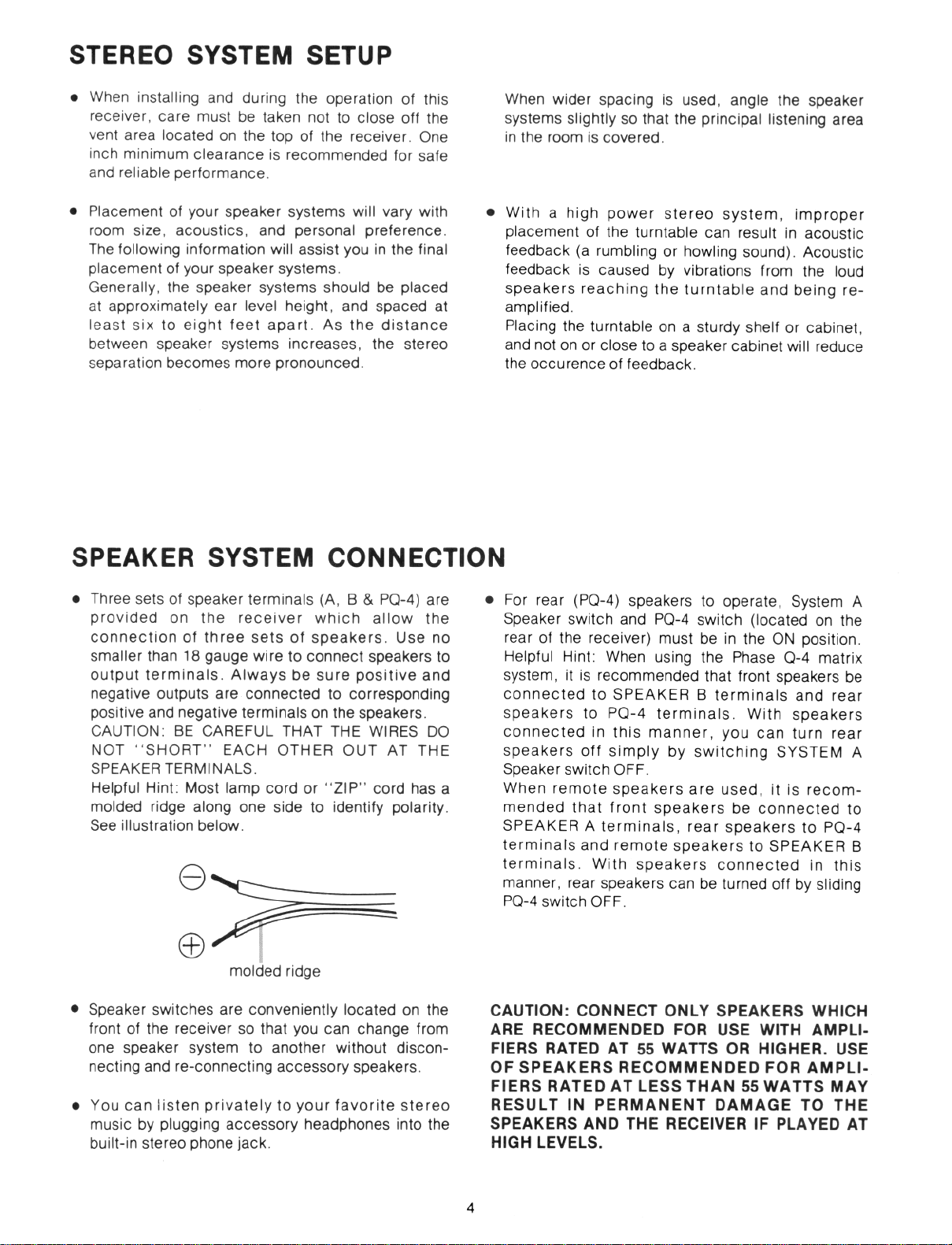
Helpful Hint: Most lamp cord or "ZIP" cord has a
molded ridge along one side to identify polarity.
See illustration below.
• Speaker switches are conveniently located on the
front of the receiver so that you can change from
one speaker system to another without disconnecting and re-connecting accessory speakers.
• You can listen privately to your favorite stereo
music by plugging accessory headphones into the
built-in stereo phone jack.
SYSTEM CONNECTION
BE CAREFUL THAT THE WIRES DO
For rear (PQ-4) speakers to operate, System A
Speaker switch and PQ-4 switch (located on the
rear of the receiver) must be in the ON position.
Helpful Hint: When using the Phase Q-4 matrix
system,
connected to SPEAKER B terminals and rear
speakers to PQ-4 terminals. With speakers
connected in this manner, you can turn rear
speakers off simply by switching SYSTEM A
Speaker switch OFF.
When remote speakers are used, it is recommended that front speakers be connected to
SPEAKER A terminals, rear speakers to PQ-4
terminals and remote speakers to SPEAKER B
terminals. With speakers connected in this
manner, rear speakers can be turned off by sliding
PQ-4 switch OFF.
CAUTION:
ARE
FIERS RATED AT 55 WATTS OR HIGHER. USE
OF SPEAKERS RECOMMENDED FOR
FIERS RATED AT LESS THAN 55 WATTS MAY
RESULT IN PERMANENT DAMAGE TO THE
SPEAKERS
HIGH
it is recommended that front speakers be
CONNECT ONLY SPEAKERS WHICH
RECOMMENDED FOR USE WITH
AND THE RECEIVER IF PLAYED AT
LEVELS.
AMPLI-
AMPLI-
4
 Loading...