

Page 1
TM
1The Roll-Up III
Roll-Up III
The Portable Large Format Digitizer
User’s Guide
Page 2

The Roll-Up III2
We at GTCO CalComp are proud of our digitizer products. We strive to bring you the best the technology has
to offer. We urge you to visit our Web site, where we will
post the latest information regarding updates and changes
that may impact the information in this User’s Guide.
Navigate to:
www.gtcocalcomp.com
Page 3

Table of Contents
What is Roll-Up III? 5
Parts Checklist 6
What You Will Need to Use Roll-Up III 6
Setting Up Your Roll-Up III 7
Software Configuration 7
Configuring Non-Wintab Applications 7
Installing the TabletWorks Driver 7
Hardware Configuration 8
USB Connection 9
RS232 Serial Connection 10
3The Roll-Up III Table of Contents
Using the SuperSet Menu 11
Changing the Digitizer’s Orientation 12
Turning the Alarm Off and On 12
Configuring Your Roll-Up III for Specific Applications 13
Example: Configuring for a Specific Application 13
Table 1: SuperSet Menu Codes for Selected Applications 14
Table 2: Configuration Details for SuperSet Menu Codes 20
Roll-Up III Tones 23
Table 3: Roll-Up III Tones 23
Introduction to the Custom Configuration Menu 24
Communication Options 24
Output Format Options 24
Mode Options 25
Using the Custom Configuration Menu 26
Care and Handling of Roll-Up III 28
Transporting Roll-Up III 29
Troubleshooting Guide 30
Procedure A: Begin Troubleshooting 31
Procedure B: Troubleshooting 32
The Tablet Configuration Utilities 34
Page 4

The Roll-Up III4 Table of Contents
Regulatory Statements and Warranty 36
Radio and Television Interference 36
Canada 36
Declaration of Conformity 37
Japan 38
Bescheinigung des Herstellers/Importeurs 38
European Union Directives 39
Limited Warranty for the Roll-Up III 40
Page 5

Overview
What is the Roll-Up III?
The Roll-Up III belongs to a class of computer input devices called
graphic tablets, or digitizers. A digitizer is an electronic tablet work
surface. The position of a transducer, a handheld cursor or stylus, on the
work surface of the Roll-Up III is converted—digitized—into data for computer processing. Data output from the Roll-Up III digitizer is in the form
of an X/Y coordinate pair that pinpoints the location of the transducer on
the tablet surface. The Roll-Up III is a specialized graphic digitizer that is
specifically designed to be portable, so it can be taken to the job site.
The Roll-Up III uses an electrostatic technology for digitizing
with blueprints and nonconductive inks. If you are using black
line drawings with conductive ink, the Super L Series Digitizers
are more appropriate.
The Roll-Up III works with many graphic, CAD, and estimating applications. These applications use the digitized data from the Roll-Up III to:
5The Roll-Up III
Determine the dimensions of objects on drawings and blueprints
Move the pointer on the display screen
Create and manipulate objects in a graphic composition
Trace a drawing, or other source material, to create an image on the
display screen
Select commands or functions from an application menu placed on
the tablet surface
Select items from a pull-down menu on the display screen
In order to send data from your Roll-Up III to your digitizing application,
your Roll-Up III must be physically connected to your computer, and it
must be able to transmit that data in such a way that the digitizing application recognizes and understands it. Before you set up your Roll-Up III,
you should determine:
The requirements of the digitizing software application you are using
Whether your digitizing application requires software drivers to communicate with the Roll-Up III
The hardware communications connection (Serial or USB) you will be
using between the Roll-Up III and the computer
Page 6

The Roll-Up III6 Checklist
Parts Checklist
Roll-Up III digitizing tablet
Transducer (stylus/pen, 4-button cursor, or 16-button cursor)
USB Cable
A CD (TabletWorks drivers, documentation, or third party software
drivers)
Accessory case – Do not discard
Cardboard tube, insert and end caps – Do not discard
Roll-Up III Quick Start
Optional Equipment
Computer interface cable with 9-pin connector for serial connection
Power supply – required only for serial installations
Deluxe Travel Bag
(Can be purchased separately)
What You Will Need to Use Roll-Up III
A computer running a Windows operating system with a USB port, or
an RS232C serial communication port. (Serial signal levels must conform to EIA RS232C specifications.)
Application software that accepts digitizer input via the Wintab API,
or application software that directly accepts digitizer input via the
computer’s RS232C serial port.
Page 7

Setting Up Your Roll-Up III
The instructions below describe how to set up your Roll-Up III. Before
you begin, please take a moment to fill out and mail the Warranty Registration Card.
Software Configuration
Software drivers provide the communication bridge between your digitizing software application and your Roll-Up III. You should install only the
drivers necessary for the Roll-Up III to work with your application software. The GTCO CalComp-supplied TabletWorks CD supports reduced
functionality Wintab and TabCon-compatible applications. If you are not
sure which drivers are required, check Table 1 on page 14, or consult
with your application vendor. A driver does not need to be installed if
you are using the Roll-Up III with the GTCO CalComp QuikRuler III.
Configuring Non-Wintab Applications
7The Roll-Up III Installation
Many application programs provide configuration information for specific
digitizers. If the Roll-Up III digitizer is not listed, you can use the configuration for GTCO Digi-Pad Type 5 or Type 5A (T5/T5A), Roll-Up II, CalComp
9100/9500, or Summagraphics Microgrid III or ID Series.
Installing the TabletWorks Driver
Insert the CD into the CD-ROM drive on your computer. The installer will
autoload. If it doesn’t, click on the Start button on the Windows Task Bar
and select Run from the menu. Type X:\setup.exe (X represents the CD
drive letter). Follow the onscreen prompts to complete the installation.
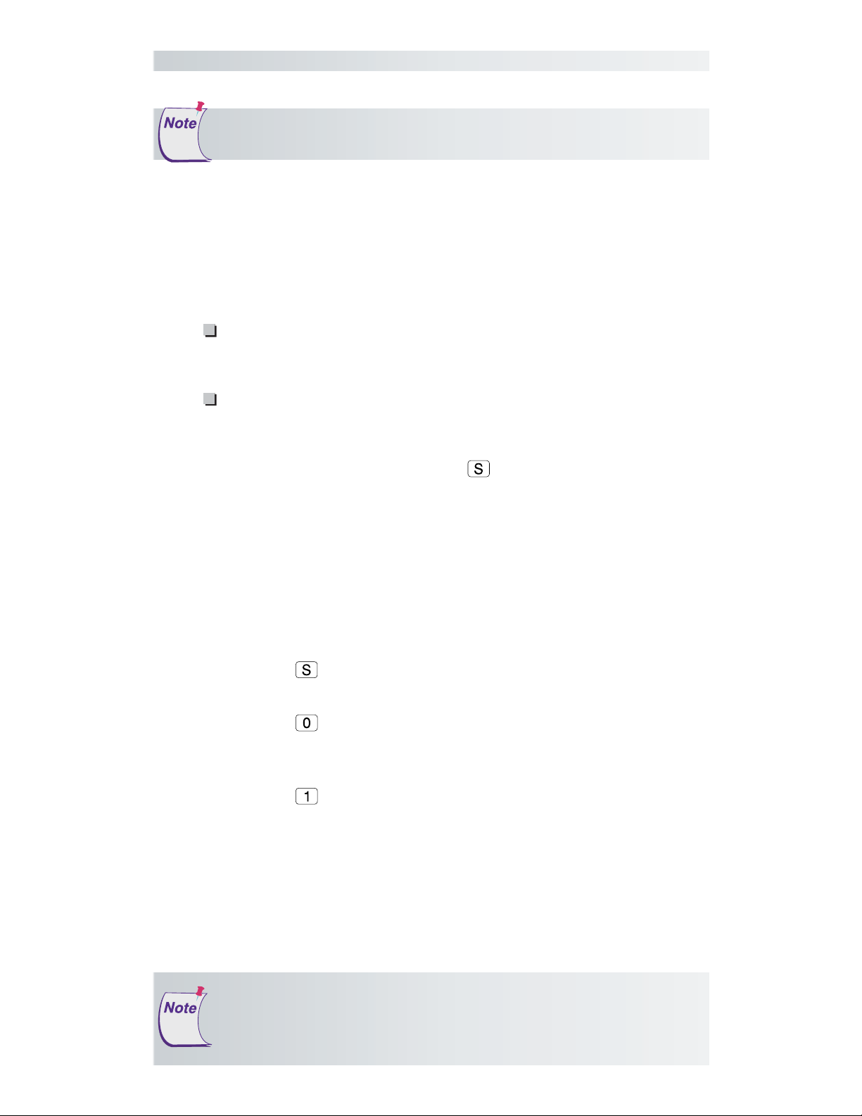
A TabletWorks icon
Task Bar. Right-click on the icon to display the TabletWorks Menu, which
provides access to all the TabletWorks features.
will display in the System Tray on the Windows
Page 8

The Roll-Up III8 Installation
Hardware Configuration
When you are using the USB interface, no data output configuration is
required. However, when you choose the optional serial interface, the
Roll-Up III must be configured to send data in a format that is compatible
with the application software. Different applications have different requirements when interacting with a digitizer. The Roll-Up III has been
designed to provide the appropriate serial requirements for a wide variety
of graphic, CAD, and estimating applications using a simple code system.
The SuperSet Menu on the surface of the Roll-Up III is used to enter the
appropriate code for the software you are using. A table in the Using the
SuperSet Menu section of this manual lists the SuperSet Codes for a wide
variety of applications.
Determine, if you haven’t already, which communication connection you
will be using—USB or Serial.
Conductive materials, inks, or electronic devices on, under, or
near the Roll-Up III can cause improper operation. See the
Troubleshooting section for more details.
1 Select a large, flat, nonmetal surface on which to place the Roll-Up III.
Clear all items from the surface.
2 Remove the Roll-Up III from its cardboard tube container and unroll it
on the selected surface.
3 Connect the transducer
– cursor or stylus – to
the appropriate jack on
the digitizer’s Connector
Panel. The connector is
Power
(DC IN)
Serial
(RS232)
Transducer
(POINTER)
USB
(USB)
Housing
keyed and will fit only
the correct jack. Do not
force it.
Roll-Up III Connector Panel
Do not attempt to remove the controller from the housing.
Doing so could damage the digitizer and void your warranty.
Page 9
9The Roll-Up III Installation
USB Connection
The Roll-Up III USB port connection is USB 1.1 and 2.0 compatible.
When the digitizer is connected to the USB port, Windows will recognize
that there is a new device connected. If Windows displays the Found
New Hardware prompt, follow the onscreen instructions to complete the
driver installation.
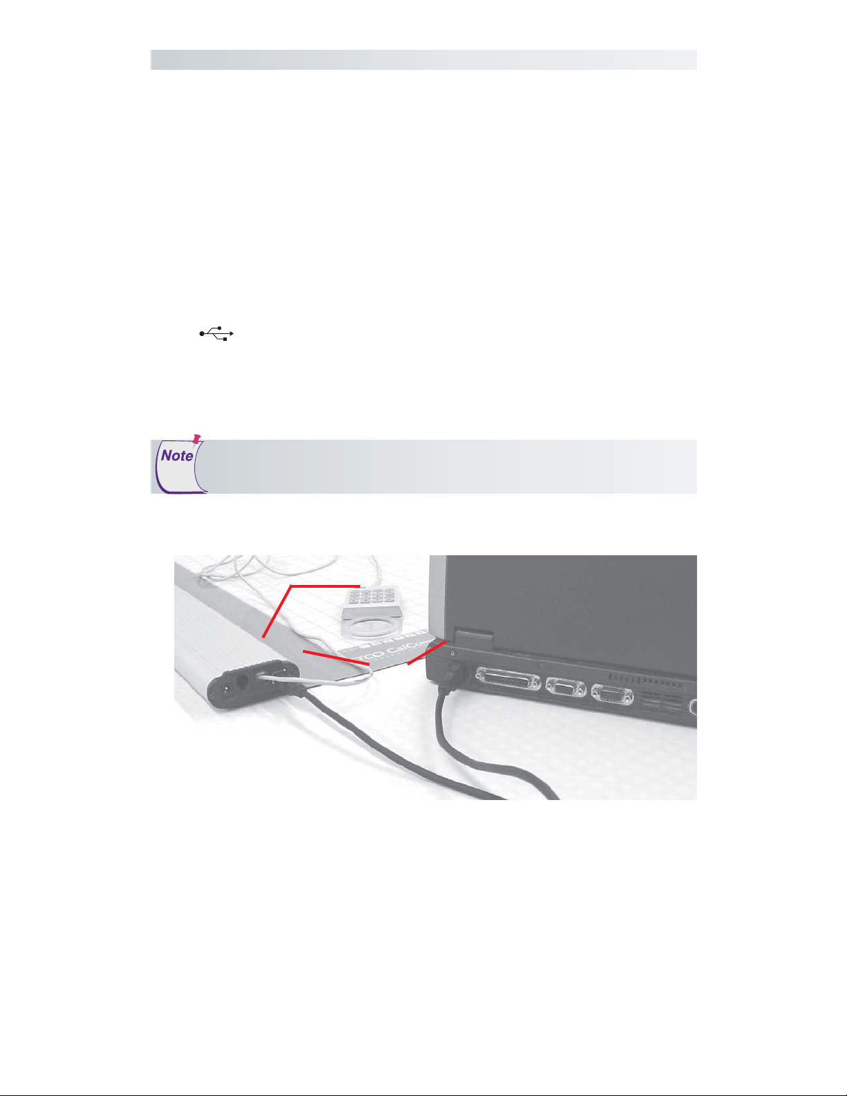
1 Connect the interface cable to the USB jack on the Roll-Up III Con-
nector Panel. The connector is keyed and will fit only the correct jack.
Do not force it.
2 Connect the other end of the USB cable to any one of the USB ports
on your computer or USB hub. The digitizer will beep four short
tones, indicating it is powered On. See the Roll-Up III Tones section
on page 23 for a complete table of the Roll-Up III tones.
3 SuperSet Codes are not applicable when using the USB connection.
Power is supplied through the USB port. No additional power
source is needed for this installation.
USB Connections
Transducer
Computer
USB
Page 10
The Roll-Up III10 Installation
RS232 Serial Connection
If your software application is not Wintab-compliant, be sure to set the
correct two-digit Application SuperSet Code before connecting the serial
cable to the computer. SuperSet Codes can be found in Table 1. If your
application is not listed in Table 1, find the configuration settings that
apply to your application in Table 2 and use the corresponding SuperSet
Code. If an appropriate SuperSet Code is not listed in Table 2, use the
Custom Configuration Menu stored in the slot on the end of the Roll-Up
III housing to configure your Roll-Up III.
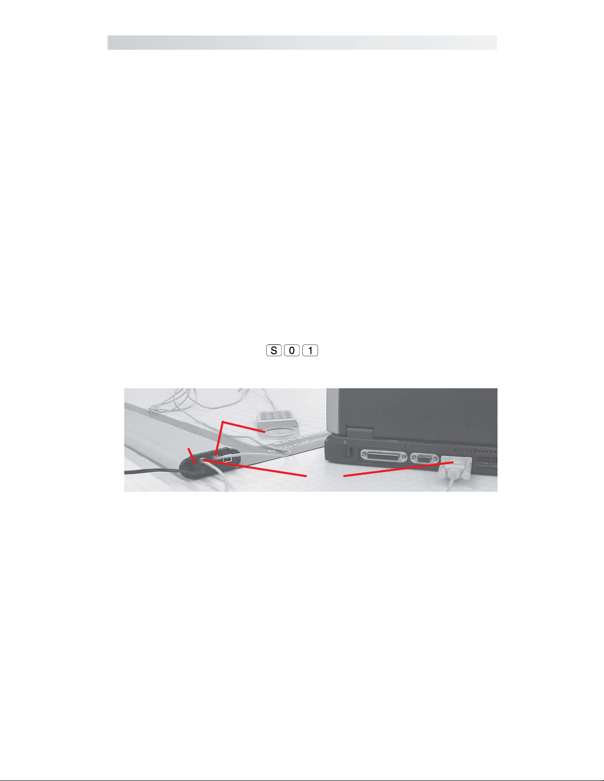
1 Plug the power supply into an AC outlet. Connect the power supply
to the appropriate jack on the Connector Panel. The digitizer will
beep four short tones (see the Roll-Up III Tones section on page 23 for
a complete table of Roll-Up III tones), indicating it is powered On.
2 Connect the RS232 serial cable to the serial jack on the Connector
Panel. The connector is keyed and will fit only the correct jack. Do not
force it.
3 Configure the SuperSet Code. The Roll-Up III comes from the factory
with the SuperSet Code
pre-configured. (See Using the
SuperSet Menu.)
Serial Connection
Transducer
Power
Serial
Computer
Page 11
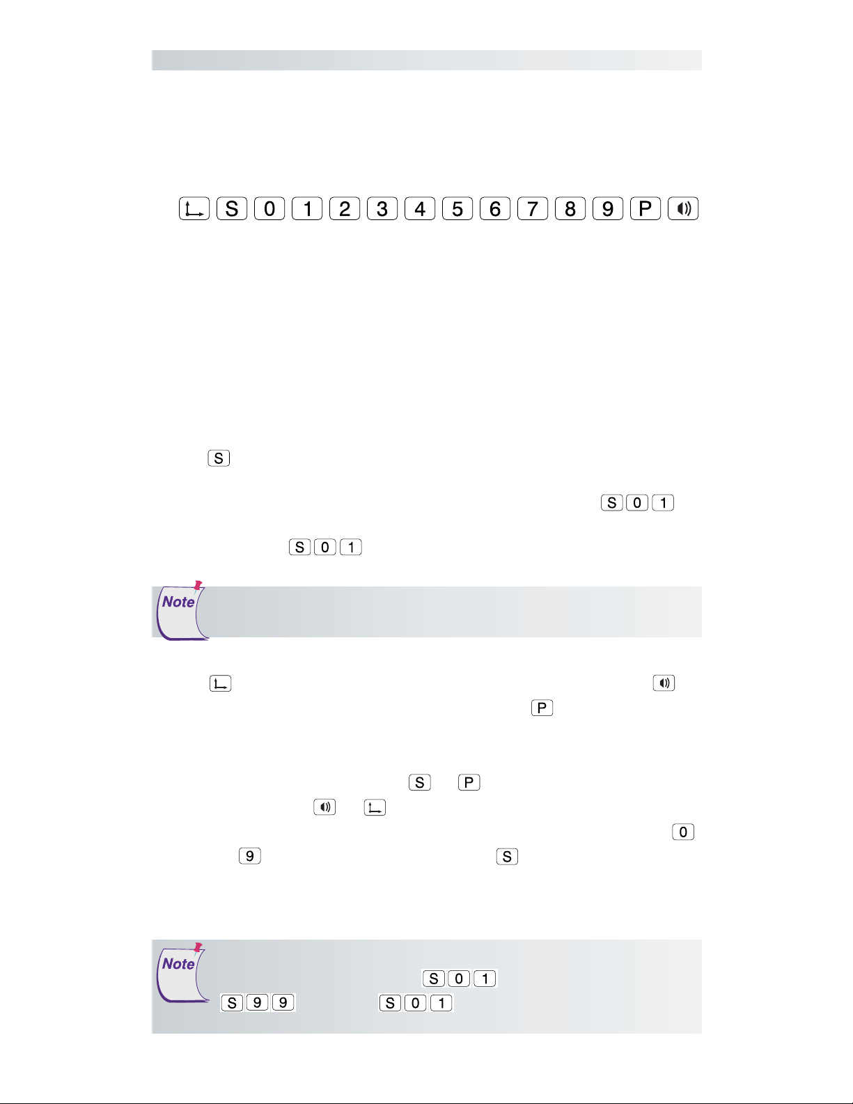
Using the SuperSet Menu
The SuperSet Menu is the row of buttons printed in the lower left and
upper right corners of the digitizer.
The SuperSet Menu makes it possible for you to configure your Roll-Up III
so that it sends the appropriate information for a serial connection to the
software you’re using on your computer (see Table 1 on page 14 for an
extensive list of digitizer software applications and their codes). It is used
to prepare the digitizer to receive specific, detailed custom configuration
information from the Custom Configuration Menu for some serial installations. In addition, the SuperSet Menu can be used for both serial and USB
connection configurations, to set and change the digitizer orientation,
and to turn the digitizer alarm off and on. Use your stylus or cursor to
click on the menu buttons to make your selections.
11The Roll-Up III The SuperSet Menu
The
are entered after Select Mode is activated. Most software supports Wintab using the TabletWorks drivers, whose SuperSet Code is
the SuperSet Menu. The Roll-Up III comes from the factory with the
SuperSet Code
The menu button sets your preferred digitizer orientation. The
button toggles the digitizer alarm off and on. The button activates the
Custom Configuration menu.
When using the SuperSet Menu, a tone will sound indicating a successful
selection when you click on the
when you click on
23 for a complete table of the Roll-Up III tones.) The number buttons
through
menu button initiates the Select Mode. Two-digit numeric codes
pre-configured.
The Select Mode will not work with the USB interface. USB talks
to Wintab drivers exclusively.
or
or
are active only after clicking on for Select Mode.
. (See the Roll-Up III Tones section on page
buttons. Four tones will sound
on
Units built before October 8, 2004, have serial Plug-N-Play
enabled for SuperSet Code
instead of
same settings, but Plug-N-Play is disabled.
. This SuperSet Code has the
. On these units, use
Page 12

The Roll-Up III12 The SuperSet Menu
Changing the Digitizer’s Orientation
The Roll-Up III lets you choose between two different digitizer orientations:
you can orient the digitizer with the controller Housing on your right (the
factory default), or you can orient it with the Housing on your left.
To change the orientation of the digitizer:
1 Turn the digitizer to the desired orientation.
2 Relocate the origin by clicking on the
Menu that is located in the lower left corner of the digitizer. You will
hear four short tones when you do this.
The orientation of the 20X24 Roll-Up III cannot be changed.
button on the SuperSet
Turning the Alarm Off and On
You can disable the alarm if you don’t want to hear a tone each time the
transducer button is pressed. When the alarm is off, you will still hear
diagnostic and menu-related tones.
To turn the alarm off and on:
Click on the
SuperSet Menu.
button – which toggles the tones on or off – on the
Page 13
RS232 Configurations
The following is relevant only for RS232 serial installations. USB
does not require configuration.
13The Roll-Up III
Configuring Your Roll-Up III for Specific Applications
To configure your Roll-Up III for use with specific applications:
1 In Table 1, find the application program you will be using with your
Roll-Up III. Note the corresponding SuperSet Code.
If your application program is not listed in Table 1, find the configuration settings in Table 2 that your application program requires and use the corresponding SuperSet Code.
If an appropriate SuperSet Code is not listed in Table 2, then use
the Custom Configuration Menu (see the Using the Custom Con-
figuration Menu section on page 26) to set up your Roll-Up III.
2 On the SuperSet Menu, click on the
digits of the SuperSet Code indicated for your application.
You will hear four short tones after a successful menu configuration.
Example: Configuring for a Specific Application
Suppose you wanted to configure your Roll-Up III to operate with
Autodesk’s AutoCAD application. You would:
1 Find the entry for AutoCAD in Table 1. The SuperSet Code is 01.
2 Click on the
short tone, indicating the digitizer is in Select Mode.
3 Click on the button on the SuperSet Menu. You will hear one
short tone. This enters the first digit of the SuperSet Code for
AutoCAD.
4 Click on the
digit of the SuperSet Code for AutoCAD.
You will hear four short tones, indicating that the configuration is complete. The Roll-Up III is now configured to operate with AutoCAD. Select
Mode is no longer active. You can begin digitizing.
button on the SuperSet Menu. You will hear one
button on the SuperSet Menu. This enters the second
button, then click on the two
For more information about
digitizer software application driver requirements,
please go to the
Technical Support section of the GTCO CalComp Web site.
Page 14

The Roll-Up III14 Table 1
Table 1: SuperSet Menu Codes for Selected Applications
SuperSet
Program Company Code
Access Bautech 39
Advanced Construction Estim. Software Shop Systems 28
A.G.E. CEIA, Inc. 75
AGTEK Earthwork Engineering (DOS) AGTEK Development Co. 09
APS Gunold & Stickma 52
ARC/CAD ESRI 01
ARC/INFO (DOS) ESRI 12
ARC/INFO ESRI 01
ARC/GIS ESRI 01
ARC/View ESRI 01
ARCT, ACA 47
ArenaSoft Estimating Arena Soft 01
ATLAS*DRAW low res Strategic Locations Planning 07
ATLAS*DRAW high res Strategic Locations Planning 08
ATLAS GIS Strategic Mapping 01
AutoCAD Autodesk, Inc. 01
Autodesk 3D Studio Autodesk, Inc. 01
AutoSketch Autodesk, Inc. 01
Autoship Coastdesign 01
Autoyacht Coastdesign 01
Autumn Zenographics 36
Batisoft 46
Best Est II Bird Construction Software 23
Bid Team Construction Data Control, Inc. 58
Bidpoint Vertigraph, Inc. 01
Bidworx for DOS Vertigraph, Inc. 31
Bidworx for Windows Vertigraph, Inc. 01
BP-340 Barudan America, Inc. 77
BuildNet Homesphere 09
Buildsoft Homesphere 09
BuildWare 1SqFt 01
BVH-Gregg Estimating BVH Gregg Incorporated 04
Cadkey low res Cadkey 18
Cadkey high res Cadkey 25
Callidus Oak Leaf Software 81
Calrson Takeoff Carlson Software 01
Carpet Estimating Systems Ramco 54
Civilcad Bloomfield Computer Services 03
CMS Estimating Contractor Management Systems 29
CNG Survey CNG Survey 05
Page 15

15The Roll-Up III Table 1
SuperSet
Program Company Code
Coastal Oceanographics 42
Cogo-PC Plus Civilsoft 01
COINS Estimating Shaker Computer & Management 41
Composer Gold Building Systems Design 42
Computer Methods Est. Computer Methods 45
Comquest Pinnacle Technology 38
Conception 3D Serbi 22
Construction Link The Construction Link 04
Contour Plus Civilsoft 01
Cost Engineer, The Cost Engineering Technologies 49
Counterpoint Counterpoint 04
CPS/SP Radian Corp. 34
Curve Digitizer West Coast Consultants 33
Cut & Fill (DOS) Paydirt Systems, Inc. 31
Cut & Fill/Precision (DOS) Paydirt/Timberline 42
Datacad Microtecture 14
DATAMINE Datamine International 82
Deed Mapping System US Soft Tech 13
DEEM Met-Coil, Ltd. 69
Design CAD American Small Business Computers 01
Designer Micrografix 02
DigiPlus Civilsoft 01
DigiPro Prosoft 66
Digitool Roctek Corp. 24
DigiWin Prosoft 68
DMS Premiere Tally Systems 57
DQ 2000 DQ Technologies, Inc. 85
DrawPlus Micrografix 02
Earth Graphics - Deluxe Earth Graphics 01
Earthwork Civilsoft 01
Earthwork 3D AGTEK Development Co. 01
Earthwork Estimating Ground Rules 01
Earthworks Tally Systems, Inc. 01
Earthworks (for Windows) Trakwear 01
-OREarthworks (for Windows) Trakwear 56
Easydij EJBIN#4 Geocomp, Ltd. 16
Easydij EJAF#2 Geocomp, Ltd. 35
Easydij EJBIN#30 Geocomp, Ltd. 19
Easy Cad Easy Cad 01
Eclare Prosoft, Inc. 66
Edge, The (DOS) Advanced Estimating 01
Page 16

The Roll-Up III16 Table 1
SuperSet
Program Company Code
Edge, The Advanced Estimating 01
Equinox Roctek Corp. 64
ESI 6000 Estimating System McCormick Systems 09
EST-Duct Estimating Technical Sales International 01
EST-Mechanical Technical Sales International 01
Estimagic Estimagic 63
Estimat-All Safeharbor Software, Inc. 54
Estimate Software Estimate Software 04
Estimation, Inc. (700 Series) Estimation, Inc. (Tradepower) 89
Estimation, Inc. (800 & Win Series) Estimation, Inc. (Tradepower) 88
Execucom Execucom Systems Corp. 36
Expose Roctek Corp. 64
Fastcad Evolution Computing 26
FastPIPE - Gold FastEST, Inc. 01
Floor Rite RFMS 01
GAP 01 GTCO CalComp 39
Gemini Excel 79
Generic CADD Generic Software, Inc. 01
Geoquest Softdesk 08
GM-SYS NW Geophysics Association, Inc. 13
GraphPlus Micrografix 02
GTCOTEST (default) GTCO CalComp 01
GTCO Wintab Driver GTCO CalComp 01
HALO products Media Cybermetics 13
Hotdij Geocomp, Ltd. 35
IBM GFIS IBM 55
Ice System, The (DOS) MC2 56
ICE 2000 MC2 01
IDRISI Clark University 74
IKE (DOS) Comput-Ability, Inc. 72
IKE Comput-Ability, Inc. 42
Imagine 8.X ERDAS, Inc. 61
Insite Earthwork Estimating Software Shop Systems 19
Insite 2 Software Shop Systems 28
Insite Sitework Insite Software 01
Insulcomp Technical Sales International 42
JAVA Jandel Scientific 24
Job Boss Small Systems Design, Inc. 39
Job Power Job Power 42
Page 17

17The Roll-Up III Table 1
SuperSet
Program Company Code
Kolvin Pro Damon, Inc. 01
Landmarke Cambridge Software, Inc. 23
Lasercad The Software Machine 01
Logdigi, Planimeter The Logic Group 12
Lumena Time Arts, Inc. 10
Mach Lite Ziatek, Inc. 04
Mach 2 Ziatek, Inc. 04
Mach 4 Ziatek, Inc. 83
MapGrafix Comgrafix, Inc. 02
Market America CACI 11
MasterBuilder (DOS) Intuit 86
MasterBuilder (2003, 2004) Intuit 01
Master Touch Integrated Measurement Systems 35
Measure Mate Measure Mate (Australia) 01
Measuremate/Measuring Calc. Paladin Measuring Systems 64
Measure Master Estimator’s Corner 51
Mechanical Construction Manager Mechanical Professional Services 73
Melco Melco 78
Metricom ADII Dynalog 71
Micromine Micromine Pty., Ltd. 27
Microstation PC Intergraph Corp. 09
MIKE (DOS) Comput-Ability, Inc. 68
MIKE Comput-Ability, Inc. 42
Mirage Zenographics 36
Molitors & Zimmer Molitors & Zimmer Estimating Syst. 67
NCE Estimator 2000 National Computer Est., Inc. 01
On Screen Take-Off OnCenter Software 01
Pagemaker Aldus Corp. 02
PAD ModaCAD 50
Paydirt Cross-Section (DOS) Spectra-Physics Laserplan, Inc. 31
Paydirt Roadwork (DOS) Spectra-Physics Laserplan, Inc. 31
Paydirt Sitework (DOS) Spectra-Physics Laserplan, Inc. 31
Paydirt Sitework Basic (DOS) Spectra-Physics Laserplan, Inc. 31
Paydirt Sitework 3.01 for Windows Spectra-Physics Laserplan, Inc. 05
Paydirt Sitework 3.2 for Windows Spectra-Physics Laserplan, Inc. 01
Paydirt Trimble Navigation 01
P-CAD Personal CAD Systems, Inc. 20
PC.BAT 46
Page 18

The Roll-Up III18 Table 1
SuperSet
Program Company Code
PC Paintbrush Z Soft 10
PC Paintbrush/Windows Z Soft 02
PC3D Jandel Scientific 24
PDS/SHADOW Polygon Software & Technologies 53
PG01 Hirsch International 22
Phoenix Estimator Phoenix Estimating 87
Picturemaker Cubicomp Corp. 15
Piping/DWV Estimating Esscomate 32
Polynest Polygon Software 40
Power Takeoff Ziatek, Inc. 04
Precision Estimating/Digitizer (DOS) Timberline Software 37
Precision Estimating/Digitizer Timberline Software 01
ProBid Promation 06
Procad Teksoft 13
Prodesign II American Small Bus. Comp., Inc. 01
ProEst Estimating Digitizer Takeoff CMS 04
ProExcel Excel 80
Professional Estimating Enterprise Computer Systems, Inc. 01
PTO CDCI 58
QED Roctek Corp. 64
Quest Earthwork Quest Solutions 01
Quest Estimator Quest Solutions 01
QuickBid OnCenter Software 01
QuickCalc Constructive Computing 58
QuickCALC - Windows Constructive Computing 01
QuickDirt Constructive Computing 23
QuickDirt - Windows Constructive Computing 01
QuickDirt II/QuickEst III Constructive Computing 58
QuickEst Constructive Computing 43
QuickEst - Windows Constructive Computing 01
QuickMeasure Tally Systems, Inc. 01
QuickPen AutoBid QuickPen International 04
QuickPen CAD QuickPen International 09
QuickPen Estimating QuickPen International 59
QuoteExpress Quote Software 01
Ramco Estimating System Ramco 54
Remodeling Estimator National Computer Estimating, Inc. 01
Right Hand Man Johnston & Associates, Inc. 04
Roadeng Softree Technical Systems, Inc. 27
Robocad, Robosolid RoboSystems International 21
Rock-it Ziatek 04
Roof Cad True North Estimating Systems 12
Page 19

Table 1
19The Roll-Up III
SuperSet
Program Company Code
Roof Estimator 3000 Essential Technology 65
SDP Civilsoft 01
Sheetmetal/Ductwork Esscomate 32
SigmaPlot Jandel Scientific 24
SigmaScan Jandel Scientific 24
SiteCalc Eagle Point 01
Smartcam Point Control Co. 17
Softplan Softdesk 08
Sonnet CAD Interworld Electronics 03
Sonnet Gap Interworld Electronics 20
Subway Roctek Corp. 64
Starbid Geac 29
Super-Duct, Super-Pipe Wendes Mechanical Consulting 48
Surpac Surpac Mining Systems 27
Takeoff 2000+ Comput-Ability 42
Takeoff Pro WinEstimator, Inc. 01
TakeoffTool US Cost 01
Terra Model (DOS) Plus 3 Software 09
Terramodel Trimble Navigation 01
Terrasoft Digital Resource Systems 01
Topographics IIID CEIA, Inc. 75
Tops II Digitizer Software Shop Systems 28
TOSCA Clark University 74
Tradesman Tradesman Software 01
Turbo Map CAD U.S. Softtech 01
Versacad Versacad Corp. 01
Vision Bidtek 70
Visual Takeoff + Comput-Ability, Inc. 42
Wall to Wall Estimator Ramco 11
WenDuct Takeoff Wendes Systems, Inc. 48
WenPipe Wendes Systems, Inc. 48
Wilcom Ltd. Wilcom Ltd. 76
Windows Microsoft 01
WinEst Pro & WinEst Pro Plus WinEstimator, Inc. 11
WinEx & WinEx Pro Roctek Corp. 01
WinMeasure DeLoach Corporation 01
WinScale Roctek Corp. 01
2D CAD West Coast Consultants 33
Page 20

Table 2
The Roll-Up III20
Table 2: Configuration Details for SuperSet Menu Codes
≈≈
Max
≈ 100 coordinates/second
≈≈
lpi = lines per inch lpmm = lines per millimeter
Code Commun. Output Options ASCII Options
01 9600,N,8,1 GTCO Binary, 1000 lpi, Cont Max
02 9600,N,8,1 GTCO Binary, 1000 lpi, Cont Incr
03 9600,N,8,1 GTCO Binary, 1000 lpi, Cont Max
04 9600,N,8,1 GTCO Binary, 1000 lpi, Point
05 9600,N,8,2 GTCO Binary, 1000 lpi, Cont 100
06 9600,N,8,1 GTCO Binary, 1000 lpi, Point
07 9600,N,8,1 GTCO Binary, 200 lpi, Cont 100
08 9600,N,8,1 GTCO Binary, 1000 lpi, Cont 100
09 9600,N,8,1 GTCO Binary, 1000 lpi, Cont 12
10 9600,N,8,1 GTCO Binary, 200 lpi, Cont Max
11 9600,N,8,1 GTCO Binary, 1000 lpi, Cont Max, Alarm
12 9600,N,8,1 GTCO ASCII, 1000 lpi, Point Pb, Sp, CR, LF
13 9600,N,8,1 GTCO Binary, 1000 lpi, Cont 12
14 9600,N,8,1 GTCO Binary, 200 lpi, Cont 100
15 9600,N,8,2 GTCO Binary, 200 lpi, Cont 100
16 9600,E,7,1 GTCO Binary, 200 lpi, Point
17 9600,E,7,2 GTCO Binary, 200 lpi, Cont Max
18 9600,E,7,2 GTCO Binary, 200 lpi, Cont Max
19 9600,N,8,1 GTCO Binary, 1000 lpi, Point
20 1200,N,8,1 GTCO Binary, 1000 lpi, Cont 100
21 4800,N,8,1 GTCO Binary, 40 lpmm, Cont 12
22 4800,N,8,1 GTCO Binary, 1000 lpi, Cont Max
23 2400,N,8,1 GTCO Binary, 1000 lpi, Cont 12
24 9600,N,8,2 GTCO Binary, 1000 lpi, Cont Max
25 9600,N,8,2 GTCO Binary, 1000 lpi, Cont Max
26 9600,N,8,2 GTCO Binary, 200 lpi, Point
27 9600,N,8,1 GTCO ASCII, 40 lpmm, Point Pb, Sp, LF
28 4800,O,7,2 GTCO ASCII, 100 lpi, Point Sp, CR, LF
29 1200,O,7,2 GTCO ASCII, 1000 lpi, Point Pb, CR, LF
30 1200,N,8,1 GTCO Binary, 40 lpmm, Cont 12
31 9600,O,7,2 GTCO ASCII, 1000 lpi, Point Pb, CR, LF
32 9600,E,7,2 GTCO ASCII, 1000 lpi, Point Sp, CR
33 2400,E,7,1 GTCO ASCII, 100 lpi, Cont 12 Pb, Sp, CR, LF
34 9600,E,7,1 GTCO ASCII, 1000 lpi, Point Pb, Sp, CR, LF
35 9600,E,7,1 GTCO ASCII, 1000 lpi, Point Pb, Sp, CR, LF
Page 21

Table 2
21The Roll-Up III
Code Commun. Output Options ASCII Options
36 9600,E,7,1 GTCO ASCII, 1000 lpi, Cont 12 Sp, CR, LF
37 2400,N,8,1 GTCO ASCII, 1000 lpi, Point Pb, Sp, CR, LF
38 2400,E,7,2 GTCO ASCII, 1000 lpi, Point Pb, Sp, CR, LF
39 1200,O,7,1 GTCO ASCII, 1000 lpi, Cont 12 Pb, CR
40 1200,N,8,1 GTCO ASCII, 1000 lpi, Point Pb, Sp, CR, LF
41 9600,E,7,1 GTCO ASCII, 1000 lpi, Point Pb, Sp, CR
42 9600,N,8,1 GTCO ASCII, 1000 lpi, Point Pb, Sp, CR, LF
43 1200,E,7,1 GTCO ASCII, 1000 lpi, Point, Alarm Pb, Sp, CR
44 9600,N,8,1 GTCO ASCII, 1000 lpi, Cont 12, Alarm Pb, Sp, CR, LF
45 9600,N,8,2 GTCO ASCII, 100 lpi, Point, Alarm Pb, CR, LF
46 9600,E,7,2 GTCO Binary, 1000 lpi, Cont 100
47 9600,O,7,2 GTCO ASCII, 1000 lpi, Cont 100 Pb, CR
48 9600,E,7,1 GTCO ASCII, 1000 lpi, Point CR, LF
49 1200,E,7,1 GTCO ASCII, 1000 lpi, Cont 12 Pb, CR
50 9600,E,8,1 GTCO ASCII, 40 lpmm, Point, Alarm Pb, Sp, CR, LF
51 1200,N,7,2 GTCO ASCII, 1000 lpi, Point Pb, CR, LF
52 9600,E,8,1 GTCO Binary, 1000 lpi, Cont 100, Alarm
53 9600,N,8,1 GTCO ASCII, 1000 lpi, Cont Max Pb, CR
54 9600,N,8,1 GTCO ASCII, 1000 lpi, Cont 12 Pb, CR
55 9600,O,7,2 GTCO ASCII, 1000 lpi, Cont Max, Alarm Pb, CR
56 9600,E,7,2 GTCO ASCII, 1000 lpi, Point Pb, Sp, CR, LF
57 9600,O,7,1 GTCO ASCII, 1000 lpi, Point Pb, Sp, CR, LF
58 9600,N,8,1 GTCO ASCII, 1000 lpi, Cont 12 Pb, CR, LF
59 1200,E,7,1 GTCO ASCII, 1000 lpi, Point, Alarm Pb, Sp, CR
60 9600,O,7,1 GTCO ASCII, 1000 lpi, Point, Alarm Pb
61 4800,N,8,1 GTCO ASCII, 1000 lpi, Point Pb, CR, LF
62 2400,N,8,1 GTCO ASCII, 1000 lpi, Cont 12 Pb, CR, LF
63 1200,O,7,1 GTCO ASCII, 1000 lpi, Point Pb, Sp, CR, LF
64 9600,N,8,1 GTCO ASCII, 1000 lpi, Point Pb, Sp, CR, LF
65 2400,N,8,1 GTCO Binary, 1000 lpi, Cont 100
66 9600,O,7,2 GTCO ASCII, 1000 lpi, Point Pb, Sp, CR, LF
67 9600,N,8,1 GTCO ASCII, 1000 lpi, Cont 12, Alarm Pb, CR
68 9600,O,7,2 GTCO ASCII, 100 lpi, Point Pb, Sp, CR, LF
69 9600,E,7,1 GTCO ASCII, 40 lpmm, Point CR, LF
70 1200,N,8,1 GTCO ASCII, 100 lpi, Point, Max, Alarm Sp, CR
Page 22

Table 2
The Roll-Up III22
Code Commun. Output Options ASCII Options
71 9600,N,8,1 GTCO Binary, 40 lpmm, Cont
72 1200,O,7,2 GTCO ASCII, 100 lpi, Point Pb, Sp, CR, LF
73 9600,N,8,1 GTCO ASCII, 1000 lpi, Point CR, LF
74 9600,N,8,1 GTCO ASCII, 1000 lpi, Cont 100, Alarm Pb, Sp, CR, LF
75 9600,N,8,1 Calcomp ASCII 3, 1000 lpi, Point CR
76 9600,N,8,1 Summa ASCII 2, 10 lpmm, Point CR
77 9600,N,8,1 Summa ASCII 2, 10 lpmm, Cont 100 CR
78 2400,N,8,1 Summa Binary, 10 lpmm, Point
79 9600,O,7,2 Summa ASCII 1, 10 lpmm, Cont 100 LF
80 9600,O,8,1 Summa Binary, 10 lpmm, Point, Alarm
81 9600,E,7,2 Summa ASCII UIOF, 40 lpmm, Point CR, LF, Decimal
82 9600,N,8,1 GTCO ASCII, 1000 lpi, Point, Max, Alarm Pb, Sp, CR, LF
83 9600,N,8,1 GTCO ASCII, 1000 lpi, Cont Incr Pb, Sp, CR
84 9600,N,8,1 GTCO ASCII, 1000 lpi, Point Pb, LF
85 9600,N,8,1 Summa ASCII UIOF, 1000 lpi, Point Pb, LF
86
*Special
87 *Special
88 *Special
89 *Special
90-98 User configuration storage locations
99 9600,N,8,1 GTCO Binary, 1000 lpi, Cont Max
*86-89 require special firmware to activate.
Page 23

Alarm Tones
Roll-Up III Tones
The Roll-Up III produces an alarm in the form of audio tones to inform
you of various events. The table below describes the kinds of tones you
might hear while operating the digitizer.
Table 3: Roll-Up Tones
Length Number of times Meaning
Short Four at power up Diagnostics passed
Short Four Successful end of menu mode
Short Once Transducer switch pressed, if the
alarm tone is enabled
Short, Continuously Transducer not attached
once per second
Medium Three Menu mode aborted
Medium Three at power up Configuration error*
Medium, Continuously Configuration Menu mode;
once per second waiting for Alignment Point 1
Short, Continuously Configuration Menu mode;
twice per second waiting for Alignment Point 2
Long, once per second, Eight long beeps, Grid disconnected*
followed by short followed by four short
Continuously on At power up Diagnostics failed*
23The Roll-Up III
Short = 1/16 second Medium = 1/4 second Long = 1/2 second
*Configuration error tones, Grid disconnected tone, or Diagnostics failed
tones indicate a serious problem. If you hear any of these tones, call GTCO
CalComp Technical Support at 410.312.9221.
You might hear tones produced by the Roll-Up III which are
actually sent by your application program. (Programs can send
commands to the digitizer to turn the audio tone generator on
and off.) If you hear tones during digitizing, and they don’t
correspond to the tones listed in the table above, they are
produced by the application program.
Page 24

The Custom Configuration Menu
This information applies to serial installations only.
The Roll-Up III24
Introduction to the
Custom Configuration Menu
The Custom Configuration Menu is used to relay configuration information to the Roll-Up III in those cases where Table 1 and Table 2 do not
supply that information or a SuperSet Menu Code for the graphic application software you are using. You will use the Custom Configuration Menu
to configure the Roll-Up III for a specific baud rate, data format and other
operating characteristics that your software requires for communication
with the digitizer. The Custom Configuration Menu is located in the slot
at the end of the Roll-Up III housing.
The configuration parameters for the Roll-Up III are divided into three
categories:
Communication Options
Output Format Options
Mode Options
Communication Options
Baud The rate, in bits/second, at which characters are transmitted
across the RS232C serial interface. Choices are: 1200, 2400, 4800,
9600, 19200, or 38400.
Data Bits Data bits represent the actual data being sent from one
device to another. Both devices must be set for the same number of
data bits. Choices are: Seven (7), or Eight (8).
Stop Bits Each character has one or two stop bits, which tell the
receiving device that a character is complete. The number of stop bits
usually does not matter. Setting for two stop bits instead of one may
overcome a mismatch in parity or data bits. Choices are: One (1), or
Two (2).
Parity One bit can be allocated for parity (parity is a simple errordetecting scheme). Both devices (sending and receiving) must be set
for the same parity—either odd parity, or even parity—-or they must be
set for no parity. Choices are: None (N), Even (E), or Odd (O).
Output Format Options
GTCO Selects GTCO-compatible formats. See Advanced Programming Information in the Roll-Up III Online Help for greater detail on
GTCO format structure. Choices are: Binary, or ASCII.
Page 25

The Custom Configuration Menu
CalComp Selects CalComp-compatible formats. See Advanced
Programming Information in the Roll-Up III Online Help for greater
detail on CalComp format structure. Choices are: Binary, ASCII 1,
ASCII 2, ASCII 3, or ASCII 4.
Summa Selects Summagraphics-compatible formats. See Advanced
Programming Information in the Roll-Up III Online Help for greater
detail on Summagraphic format structure. Choices are: Binary, or
ASCII.
ASCII formats can be modified by including, or excluding, a button code,
space, decimal point, carriage return, or line feed, depending on whether
GTCO, CalComp, or Summa formats have been selected.
Button Defines whether the Pushbutton (Pb) value is included in the
ASCII output report. This option is available only with GTCO formats.
Choices are: Include, or Exclude.
Space Defines whether the Space (Sp) character (hex 20) is included
in the ASCII output report as a delimiter between the X and Y coordinate values. This option is available only in GTCO formats. Choices
are: Include, or Exclude.
25The Roll-Up III
Decimal Defines whether the period character (hex 2E) is included
in the ASCII output report between the units and tenths digits. This
option is available only in Summagraphics formats. Choices are:
Include, or Exclude.
Return Defines whether the Carriage Return (CR) character (hex 0D)
is included in the ASCII output report as a terminator. This option is
available in GTCO and Summagraphics formats. Choices are: Include,
or Exclude.
Line Feed Defines whether the Line Feed (LF) character (hex 0A) is
included in the ASCII output report as a terminator. This option is
available in GTCO, CalComp and Summagraphics formats. Choices
are: Include, or Exclude.
Mode Options
Mode Defines how output reports are sent from the digitizer.
Choices are: Point, Line, Continuous, Line Incremental, or
Continuous Incremental.
Rate Determines how fast output reports will be transmitted from
the digitizer. Choices are: 12, 50, or 100 reports per second.
Resolution The smallest reported value returned by the digitizer.
Choices are: 1000 lpi, 2000 lpi, 4000 lpi, 40 lpmm, 100 lpmm, or 150
lpmm.
See the Advanced Programming Information section in the Roll-Up III
Online Help at www.gtcocalcomp.com for more details.
Page 26
The Custom Configuration Menu
The Roll-Up III26
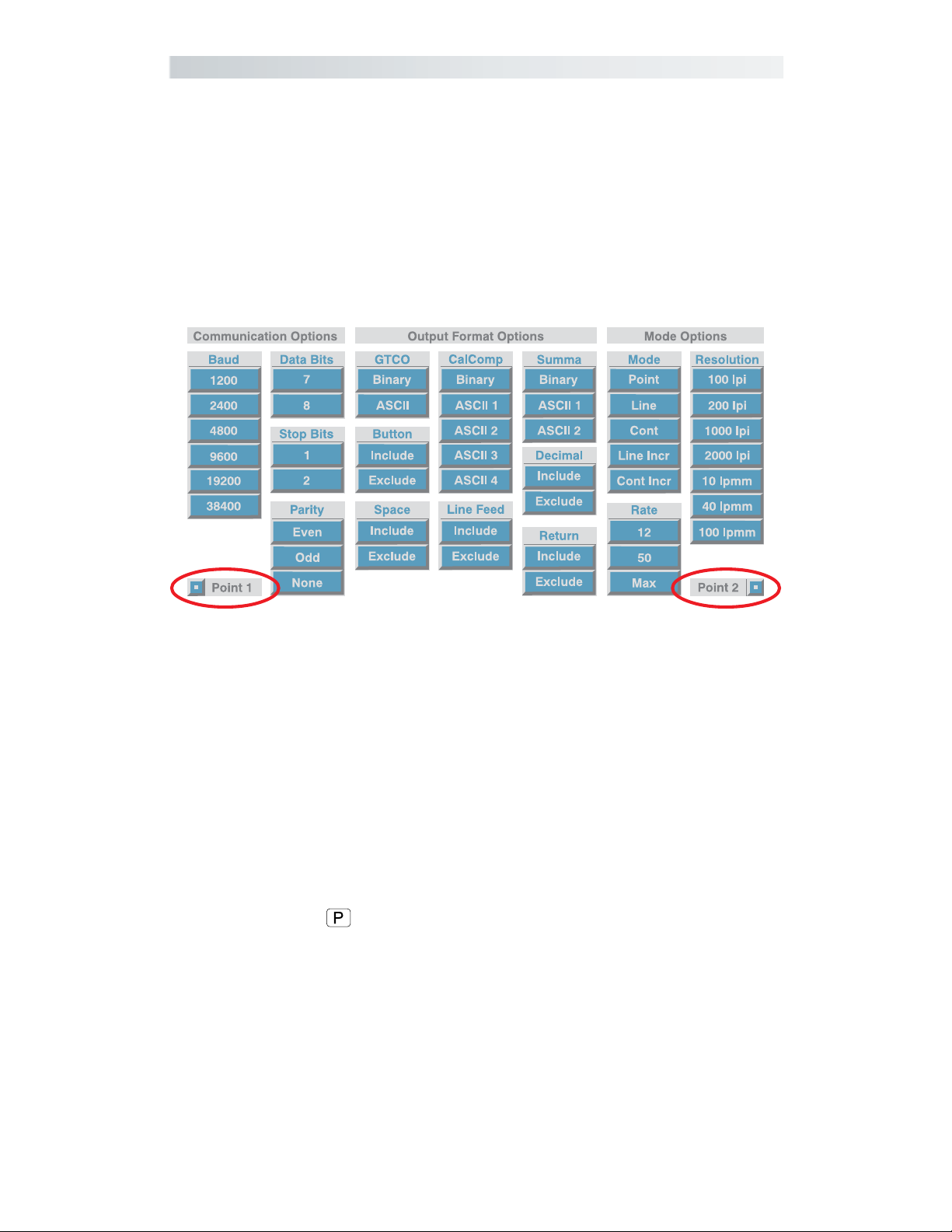
Using the Custom Configuration Menu
If your application is not represented in the SuperSet Menu and does not
have a SuperSet Code, or if a different configuration is required, you can
use the Custom Configuration Menu to configure the Roll-Up III. The
Custom Configuration Menu, pictured here, is stored in the slot at the
end of the Roll-Up III housing. The Custom Configuration Menu replaces
the 24 switches that were associated with older GTCO digitizers.
Custom Configuration Menu Alignment Points
The configurations you set up can be stored for recall at a later time in
any of the nine user-definable SuperSet Menu locations—codes 90
through 98. This allows the Roll-Up III configuration to be easily switched
between applications, when you have such a requirement.
To configure the Roll-Up III using the Custom Configuration Menu:
1 Place the Custom Configuration Menu card, or the copy, anywhere in
the active area of the digitizer. The entire menu must be in the active
area. A piece of tape can be used to keep it in place during the configuration process.
2 Click on the
slowly, indicating that the Custom Configuration Menu Mode is now
ready to receive Alignment Point information.
3 You will tell the Controller where the Custom Configuration Menu is
physically located on the digitizer by clicking on the Alignment Points.
Click on Alignment Point 1, the white dot in the small blue square
labeled Point 1, in the lower left corner of the menu. The alarm will
beep rapidly, indicating that the system is waiting to receive Alignment Point 2.
button on the SuperSet Menu. The alarm will beep
4 Click on Alignment Point 2, the white dot in the small blue square
labeled Point 2, in the lower right corner of the menu. After Alignment
Page 27

The Custom Configuration Menu
27The Roll-Up III
Point 2 is selected, the alarm will sound only if the transducer passes
over an active block on the menu.
If invalid alignment points are selected, or if the menu is not
entirely in the digitizer’s active area, the Custom Configuration
Menu Mode will be aborted. This is indicated by three medium
tones from the alarm.
5 Configure the Roll-Up III by selecting the function blocks that corre-
spond to the settings your software will need to communicate with
the digitizer.
6 Review the configuration to ensure that the proper settings have been
selected. Pass the transducer down each group of options; the alarm
will sound when the transducer is over the active choice. Some
groups may be inactive, based on the options selected. Click on a
desired setting in a group to change it. To cancel all settings, click in
the active area outside the menu.
7 When you have finished making your selections, you can save the
configuration. If you choose to save it temporarily, the configuration
will be remembered only until another SuperSet Code is entered. If
you never change the configuration of your Roll-Up III from the custom one you just entered, the temporary configuration will always be
used. However, if you expect to be switching between configurations
and want to save the custom one for later recall, you can assign the
configuration to a special user-definable SuperSet Code.
To save the configuration temporarily:
Click on the button on the SuperSet Menu. You will hear four
short tones to indicate you successfully saved the custom configuration. The configuration is saved in a temporary location, where it
will be retained even when the unit is powered off or reset. However, if another SuperSet Code is entered, this temporary configuration is lost and cannot be recalled without configuring the RollUp III again.
To save the configuration in a user-definable location:
As indicated in Table 2, the codes 90 through 98 are available as
storage locations for user-defined custom configurations. Simply
click on the
90 and 98. Your custom configuration will be saved under that
code number for future recall. You will hear four short tones when
you successfully save the custom configuration. Saved configurations allow you to switch quickly between applications. Storage
locations 90 through 98 retain the saved configurations even when
the Roll-Up III is turned off or reset.
button and click on a two-digit number between
Page 28

Care and Handling
The Roll-Up III28
Care and Handling of Roll-Up III
The Roll-Up III was designed to be both portable and durable. As with any
product, it requires proper care and handling for reliable operation. By
following these recommendations, your Roll-Up III digitizer will provide
you with many years of service:
Always use the Roll-Up III on a flat surface, where no part of the unit is
unsupported.
Before moving the digitizer, disconnect the transducer, interface
cable, and power supply, if connected.
Before moving the digitizer, roll it up. The housing along the side of
the digitizer is designed as a rolling aid and it allows you to easily
control the rolling action. (See the Transporting Roll-Up III section on
the next page for specific moving instructions.)
Don’t permanently attach anything to the digitizer.
Don’t use sharp instruments on or near the Roll-Up III to avoid
scratching or cutting it. Cuts in the digitizer will void your warranty.
Don’t crease, dent, or abuse the digitizer. Creases can damage the
digitizer structure. Severe creases or abuse will void your warranty.
Clean your Roll-Up III with any mild, nonabrasive household cleaner.
Rubbing alcohol is recommended. Do not apply liquid directly to the
surface of the Roll-Up III. Spray the cleaning solution on a cloth and
wipe it over the surface. After cleaning, dry the surface to avoid
possible digitizing errors.
Page 29

Transporting Roll-Up III
You must transport your Roll-Up III using the factory-supplied shipping
materials—heavy gauge cardboard tube, insert and end caps. Failure to do
so could result in serious damage to the unit and may void your warranty.
1 Disconnect the transducer and interface cable from the Roll-Up III and
the computer. Remove all material from the digitizer.
2 Grasp the controller housing firmly with both hands and roll it toward
the opposite side of the digitizer. The housing and the printing on the
digitizer surface must be on the inside of the roll. The roll diameter
should be just smaller than the inside diameter of the factory-supplied
shipping tube. When correctly rolled, only the digitizer’s black back
will be exposed.
Do not roll the Roll-Up III too tightly. Rolling too tightly
could damage the electronic grid.
29The Roll-Up III Transporting
3 Insert the rolled digitizer into the shipping tube and allow it to fully
unroll against the inside of the tube. Place the factory-supplied insert
into the center of the rolled digitizer for support.
4 Place the accessories in the accessory case and put it inside the
hollow insert. Place the factory-supplied end caps on the tube to seal
it. Place the tube in the optional Deluxe Travel Bag.
The Deluxe Travel Bag is intended to be used only in
conjunction with the factory-supplied heavy gauge cardboard
tube, insert and end caps. The Deluxe Travel Bag does not
provide complete protection if used alone. The product will
be subject to damage not covered by the warranty, if not
protected by the tube, insert and end caps. If you have misplaced or disposed of these items, contact GTCO CalComp
(410.381.6688) for replacements.
Page 30

The Roll-Up III30 Troubleshooting Guide
Troubleshooting Guide
As with any computer peripheral, Roll-Up III problems sometimes do
occur. Most of these problems are easy to find and correct. This troubleshooting guide provides clear instructions for finding and solving all
common digitizer problems. In most cases, you will be able to quickly
take care of the problem yourself by following these steps:
1 Install properly first.
This troubleshooting guide assumes you have already correctly installed
your Roll-Up III according to the detailed instructions in the Setting Up
Your Roll-Up III section. If you have not followed the step-by-step instructions in that section, do so now.
2 Work through the troubleshooting flowcharts on the following
pages in this troubleshooting guide.
Record any unusual observations. Your notes will be useful if you need
assistance from GTCO CalComp later.
3 If your system still doesn’t work...
Call our Technical Support Department at 410.312.9221. Be prepared to
discuss the observations you made while troubleshooting. A Technical
Support Specialist will help you resolve the problem as quickly as possible.
Refer to the Roll-Up III Tones table on page 23, while using this
Troubleshooting Guide.
If you are experiencing erratic behavior with your digitizer, make sure
that no conductive materials are being used. This includes the graphite in
pencil lead, some black plotter ink, and digitizing on plastic or Mylar. No
electronic devices should be sitting on or near the digitizer, including
keyboards, mice, calculators, etc. If any of these describes normal working
conditions, the Super L Series Digitizers would be more suited to your
environment.
Tablet Not Found: If you are using a USB connection and the
digitizer is not found, either disconnect and reconnect the USB
cable, or restart the system.
Load Driver: If a window pops up telling you to load a driver
every time you power-on, and your application software doesn’t
use a driver, you should change the power-on default SuperSet
Code to
, or load the driver from the TabletWorks CD.
Page 31
Troubleshooting Guide
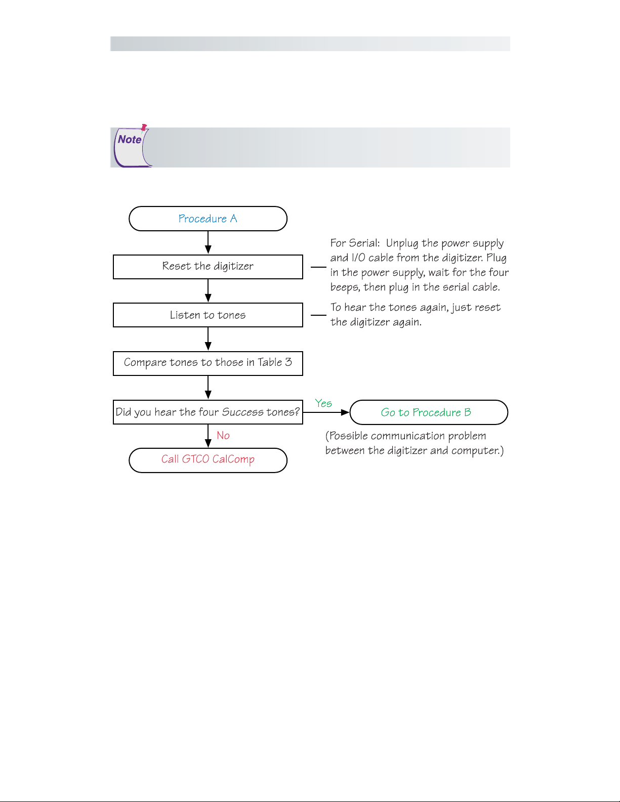
Procedure A: Begin Troubleshooting
This procedure should only be used to troubleshoot serial connections.
31The Roll-Up III
Page 32

Troubleshooting
Procedure B: Troubleshooting
The Roll-Up III32
Page 33

33The Roll-Up III
This page left blank intentionally.
Page 34

The Tablet Configuration Utilities
The Roll-Up III34
Using the Tablet Configuration Utilities
If your application is not represented in the SuperSet Menu and does not
have a SuperSet Code, or if a different configuration is required, you can
use the Tablet Configuration Utilities to configure the Roll-Up III. The
Tablet Configuration Utilities replace the 24 switches that were associated
with older GTCO digitizers and the Custom Configuration Menu Card
used with the Roll-Up II.
To configure the Roll-Up III with the Tablet Configuration Utilities:
1 Make sure the Roll-Up III is plugged into a Serial Port, powered On,
and all the tablet drivers have been uninstalled or disabled.
2 Install the Tablet Configuration Utilities from the Select Utility Software
to Install section on the TabletWorks CD, or download them from
www.gtcocalcomp.com.
3 After the installation has completed, run the Tablet Configuration
Utilities from the Programs list under GTCO CalComp TCU.
4 The Tablet Configuration Utilities will begin searching the Serial Ports
for a supported tablet.
a) If the tablet is found, information about the tablet will display
under Device Info near the bottom of the screen.
b) If the tablet is not found, a message will appear under Device Info
near the bottom of the screen.
i) If Wintab files were found, it is possible that the TabletWorks)
driver has the Serial Port open.
ii) If the Serial Port is open by another application, it will not be
displayed under System Info. Close any application, or uninstall
any driver that is using the Serial Port and select Refresh System
Info from the File drop-down list at the top of the screen. Click
on the Serial Port icon under System Info to search that Serial
Port.
The Tablet Configuration Utilities can use the TabletWorks driver
to test the tablet, but it must be communicating directly with the
tablet, via the Serial Port, in order to configure it.
5 Once the Roll-Up III has been found on a Serial Port, select Advanced
Configuration from the Options drop-down list at the top of the
screen.
a) If Advanced Configuration is not an option, make sure Wintab
Compatible Driver is not listed under Device Info.
Page 35

The Tablet Configuration Utilities
6 Select a predefined, 01 through 55, SuperSet Code, or select one of
the User Defined, 90 through 98, SuperSet Codes to customize.
a) User Defined (90 through 98) SuperSet Codes are initially read
from the tablet when the Advanced Configuration screen opens.
This is to prevent loss of custom settings. Selecting Read Current
Settings from the Options menu will:
i) Read the Power-Up settings and User Defined SuperSet Codes
from the tablet.
ii) Overwrite all Custom Settings not yet saved to the tablet.
b) Restore Factory Settings from the Options menu will prompt for:
i) Power-Up settings reset to factory default and set current.
ii) User Defined SuperSet Codes cleared and reset to factory
default.
7 After making your selections, choose one of the following from the
File menu at the top of the screen.
35The Roll-Up III
a) Save Temporary Settings will configure the tablet as shown until
the tablet is powered off, reset, or another SuperSet Code is
selected.
i) After saving temporary settings, select File/Exit to test with
other applications. This will leave the tablet configured to the
temporary settings selected and close the Serial Port, enabling
other applications to communicate with the tablet.
b) Save Power-Up Settings will configure the tablet as shown. Every
time the tablet is powered off and back on, or reset, it will restore
these settings.
c) Save Custom Settings will reconfigure all nine of the tablet’s User
Defined SuperSet Codes to the settings specified in the corresponding SuperSet Code drop-down list.
i) You can click on the SuperSet Menu buttons on the tablet
using the tablet’s cursor to activate these configurations:
S plus 90 through 98.
8 When you have finished, select Exit or Close from the File menu.
a) Exit will close the Tablet Configuration Utilities.
b) Close will exit the Advanced Configuration Screen and return to
the Tablet Configuration Utilities window.
Page 36

Regulatory Statements
The Roll-Up III36
Regulatory Statements and Warranty
Radio and Television Interference
The user is cautioned that any changes or modifications not expressly
approved by the party responsible for compliance could void the user’s
authority to operate the equipment.
This equipment has been tested and found to comply with the limits of a
Class B digital device, pursuant to Part 15 of the FCC rules. These limits
are designed to provide reasonable protection against harmful interference in a residential installation. This equipment generates, uses and can
radiate radio frequency energy and, if not installed and used in accordance with the instructions, may cause harmful interference to radio
communications. However, there is no guarantee the interference will
not occur in a particular installation. If this equipment does cause harmful
interference to radio or television reception, which can be determined by
turning the equipment off and on, the user is encouraged to try to correct
the interference by one or more of the following measures:
Reorient or relocate the receiving antenna
Increase the separation between the equipment and the receiver
Connect the equipment into an outlet on a circuit different from that
to which the receiver is connected.
Reorient or coil cables.
Consult the dealer or an experienced Radio/TV technician for help.
Any cables the user adds to the device must be shielded to
be in compliance with the FCC standards. Any unauthorized modification to this device could result in the revocation of the end user’s authority to operate this device.
Canada
This digital apparatus does not exceed the Class B limits for radio noise
emissions from digital apparatus as set out in the radio interference
regulations of the Canadian Department of Communications.
Le present appareil numérique n’emet pas bruits radioelectriques depassant
les limites applicables aux appareils numériques de Classe B prescrites dans
le réglement sur le brouillage radioelectrique edicte par le Ministere des
Communications du Canada.
Page 37

Declaration of Conformity
The “CE” mark on this device indicates compliance under the EMC 89/
336/EEC Directive.
Declaration of conformity according to ISO/IEC Guide 22 and EN 45014
Manufacturer’s Name: GTCO CalComp, Inc.
Manufacturer’s Address: 7125 Riverwood Drive
Columbia, MD 21046
U.S.A.
Importer’s Name: GTCO CalComp GmbH
Importer’s Address: Kreiller Strasse 24
Munich 81673
Germany
declares, that the product
37The Roll-Up III Declaration of Conformity
Product Name: Roll-Up III Digitizer
Model Numbers: RUD3-2024, RUD3-3036, RUD3-3648
Product Options: All
conforms to the following product specifications:
Safety: EN60950-1:2001, IEC60950:2001 IEC60950:1999-04
UL60950-1/CSA-C22.2 NO.60950-1-03
EMC: EN55022:1998, A1:2000 A2:2003
EMI: EN55024:1998, A1:2000 A2:2003
EN 61000-3-2 Harmonic Current Emissions
EN 61000-3-3 Voltage Fluctuations and Flicker
EN 61000-4-2; Direct ESD/Indirect ESD
EN 61000-4-3; Radiated Susceptibility:
EN 61000-4-4; Electrical Fast Transients:
EN 61000-4-5; Surge:
EN 61000-4-6; Conducted RF:
EN 61000-4-8; Magnetic Field:
EN 61000-4-11; Voltage Dips and Interruptions:
RoHS: “-R” labelled products conform to DIRECTIVE
2002/95/EC. These products are RoHS-compliant.
following the provisions of Council Directive 89/336/EEC (EMC Directive)
and Couuncil Directive 73/23/EEC (Low Voltage Directive) where applicable.
Scottsdale, Arizona, U.S.A. 6-15-2004 Dana Doubrava
Location Date Engineering Manager
Page 38

Japan
Bescheinigung des Herstellers/Importeurs
Heirmit wird bescheinigt, dass der/die/das
3036R
The Roll-Up III38 Regulatory Statements
(Geraet, Typ, Bezeichnung)
im Uebereinstimmung mit den Bestimmungen der
Vfg 1046/1984
(Amtsblattverfuegung)
Funk-Entstort ist.
Der Deutschen Bundespost wurde das Inverkehrbringen dieses Geraetes
angezeigt und die Berechtigung zur Ueberpruefung der Serie auf
Einhaltung der Bestimmungen eingeraumt.
GTCO CalComp, Inc.
(Name des Herstellers/Importeurs)
Dieses Geraet wurde einzeln sowohl als auch in einer Anlage, die einen
normalen Anwendungsfall nachbildet, auf die Einhaltung der Funkentstoerbestimmungen geprueft. Es ist jodoch moeglich, dass die Funkentstoerbestimmungen unter unguenstigen Umstaenden bei anderen
Geraetekombinationen nicht eingehalten werden. Fuer die Einhaltung
der Funk-entstoerbestimmungen seiner gesamten Anlage, in der dieses
Geraet betrieben wird, ist der Betrieber verantwortlich.
Einhaltung mit betreffenden Bestimmungen kommt darauf an, dass
geschirmte Ausfuhrungen gebraucht werden. Fuer die beschaffung
richtiger Ausfuhrungen ist der Betrieber verantwirtlich.
Page 39

39The Roll-Up III European Union Directives
European Union Emission Directive
This product is in conformity with the protection requirements of EU
Council Directive 89/366/ECC on the approximation of the laws of the
Member States relating to electromagnetic compatibility.
This product has been tested and found to comply with the limits for
Class B Information Technology Equipment according to CISPR 22/
European Standard EN55022. The limits for Class B equipment were
derived for typical industrial environments to provide reasonable protection against interference with licensed communication devices.
European Union WEEE Directive
The manufacture of this equipment required the extraction and use of
natural resources. It may contain hazardous substances that could impact
health and the environment.
• In order to avoid the dissemination of the hazardous substances into
the environment and to diminish the pressure on our natural resources, we encourage you to return this product to the appropriate
take-back system facility. These facilities reuse or recycle most of the
materials in this equipment in a responsible way.
• The crossed-out wheeled bin symbol below invites you to use these
take-back systems.
• If you need more information about the collection, reuse and recycling systems in your area, please contact your local or regional waste
authority.
• Further information about the responsible end-of-life management of
this and other GTCO CalComp products is available on our Web
site at www.gtcocalcomp.com.
European Contact:
GTCO CalComp GmbH
Kreiller Strasse 24
81673 Munich
Germany
Tel: + 49 (0) 89 370012-0
Fax: + 49 (0) 89 370012-12
Page 40

Warranty
The Roll-Up III40
Limited Warranty for the Roll-Up III
GTCO CalComp, Inc. warrants these products to be free from defects in material and workmanship
under the following terms. Complete and return the enclosed warranty registration card to ensure that
your products are covered with this warranty.
Coverage
Parts and labor are warranted for two (2) years from the date of the first consumer purchase for the
digitizer tablet, controller, transducers, and tablet accessories. Power supply and cables are warranted
for one (1) year. This warranty applies to the original consumer purchaser only.
Within the European Union, the warranty period is two (2) years, as mandated by the EU. Contact your
local dealer or distributor for additional warranty information.
Warranty is only valid if original consumer’s purchase or lease date is less than or equal to six months
from the original GTCO CalComp sale date. This information will be captured by the system serial
number and confirmed by the reseller’s purchase order.
A nominal Warranty Handling Fee will be charged after the first year of use and calculated from the
date of original consumer purchase. This payment may be made by Visa, MasterCard or American
Express. A copy of the sales receipt or invoice will be required for warranty verification.
Conditions
Except as specified below, this warranty covers all defects in material or workmanship in the products.
The following are not covered by the warranty:
1 Any product on which the serial number has been defaced, modified or removed (if applicable).
2 Damage, deterioration or malfunction resulting from:
a Accident, misuse, abuse, neglect, fire, water, lightening or other acts of nature, unauthorized
modification for any purpose, unauthorized product modification, or failure to follow
instructions supplied with the product.
b Repair or attempted repair by anyone not authorized by GTCO CalComp.
c Any damage in shipment of the product (claims must be presented to the carrier).
d Any other cause which does not relate to a manufacturing defect.
3 Any product not sold or leased to a consumer within six months of GTCO CALCOMP’s original
sale date.
GTCO CalComp will pay all labor and material expenses for covered items, but we will not pay for the
following:
1 Removal or installation charges.
2 Costs for initial technical adjustments (set up), including adjustment of user controls.
3 Certain shipping charges. (Payment of shipping charges is discussed in the next section of this
warranty.)
4 Packaging costs. (Customers should keep their boxes.)
Warranty Service Procedures
1 To obtain service on your GTCO CalComp product, contact the Technical Support Department to
receive a Return Material Authorization Number (RMA#) and shipping instructions by calling:
In United States: (425) 223-4311 (PST)
In Europe: +49 (0) 89 370012-0 (CET)
2 Ship the product to GTCO CalComp with the RMA# marked clearly on the outside of the box.
Without a clearly marked RMA# on the shipping box, GTCO CalComp reserves the right to refuse
shipment.
3 Although you must pay any shipping charges to ship the product to GTCO CalComp for warranty
service, GTCO CalComp will pay the return shipping charges for ground shipment. Other shipping
options are available at an additional fee.
4 Whenever warranty service is required, the original dated sales invoice (or a copy) must be
presented as proof of warranty coverage, and should be included in shipment of the product.
Please also include your name, address, telephone number, fax number, email address, and a
description of the problem.
5 If GTCO CalComp determines that the unit is not defective within the terms of the warranty, the
consumer shall pay the cost of all freight charges, as well as any repair charges.
Technical Support
Web-based Technical Support is available free of charge at:
driver releases, as well as comprehensive technical support, troubleshooting, Technical Bulletins and
www.gtcocalcomp.ca, where current
Page 41

Warranty
FAQs can be found.
Please contact our Technical Support Department:
In United States: (425) 223-4311 (PST)
In Europe: +49 (0) 89 370012-0 (CET)
You can also fax your request to:
In United States: (425) 223-4311 (PST)
In Europe: +49 (0) 89 370012-12 (CET)
Disclaimer of Unstated Warranties
The warranty printed above is the only warranty applicable to this purchase. ALL OTHER
WARRANTIES, EXPRESS OR IMPLIED, INCLUDING, BUT NOT LIMITED TO, THE IMPLIED
WARRANTIES OF MERCHANTABILITY AND FITNESS FOR A PARTICULAR PURPOSE ARE
DISCLAIMED. Assuming the warranty above stated is otherwise applicable, it is expressly understood
and agreed that GTCO CalComp’s sole liability whether in contract, tort, under any warranty, in
negligence or otherwise shall be for the repair or replacement of the defective parts and under no
circumstances shall GTCO CalComp be liable for special, indirect or consequential damages. The price
stated and paid for the equipment is a consideration in limiting GTCO CalComp’s liability.
Notice
Some states and provinces do not allow the exclusion or limitation of incidental or consequential
damages, so the above exclusion may not apply to you. This warranty gives you specific legal rights,
and you may have other rights, which vary from state to state, or province to province.
To obtain service on your GTCO CalComp product, call our Technical Support Department at (425)223-4311
(PST), or fax us at (877) FAX-IECI (PST); in Europe call +49 (0) 89 370012-0 (CET), or fax us
at +49 (0) 89 370012-12 (CET).
We can also be contacted through our Web site at
www.gtcocalcomp.ca.
41The Roll-Up III
Important! All products returned to GTCO CalComp for service must have prior approval in the form
of a Return Merchandise Number (RMA#), which can be obtained by calling the Technical Support
Department.
Page 42

The Roll-Up III42
Corporate Headquarters
7125 Riverwood Drive
Columbia, Maryland 21046
Tel: 425.223.4311
Support: 425.223.4311
Sales: 877.902.2979
Fax: 877.FAX.IECI
www.gtcocalcomp.ca
Support:
European Headquarters
GTCO CalComp GmbH
Kreiller Strasse 24
81673 Munich
Germany
Tel: + 49 (0) 89 370012-0
Fax: + 49 (0) 89 370012-12
425.223.4311
TM
ROLL-UP III
Copyright© 2008 GTCO CalComp, Inc.
Roll-Up III is a trademark of GTCO CalComp, Inc.
All other products and company names are the trade-
marks or registered trademarks of their
respective owners.
The information contained in this document is subject to change
without notice. GTCO CalComp assumes no responsibility for technical,
or editorial errors, or omissions that may appear in this document, or
for the use of this material. Nor does GTCO CalComp make any
commitment to update the information contained in this document.
This document contains proprietary information which is protected
by copyright. All rights reserved. No part of this document can be
photocopied or reproduced in any form without the prior, written
consent of GTCO CalComp, Inc.
37-00811-01 Rev. G
 Loading...